UNDER STANDING RADIO FREQUENCY Badger Meter, Inc.
|
|
|
- Ariel Clark
- 5 years ago
- Views:
Transcription
1 UNDER STANDING RADIO FREQUENCY

2 UNDERSTANDING RADIO FREQUENCY Regional Sales Meeting March 1-2, 2011 Brian Fiut Sr. Product Manager Itron Inc. Liberty Lake, WA August 25, 2010
3 RADIO PROPAGATION Radio consists of electromagnetic waves measured in Hertz, or waves per second kilo = thousands = khz Mega = millions = MHz Giga = billions = GHz 3
4 RADIO SPECTRUM Type Frequency Applications ELF Hz Remote Control VF 300 3,000 Hz Voice, Analog Phone VLF 3 30 KHz Submarine, Long-Range LF KHz Long-Range, Marine Beacon MF 300 KHz 3MHz AM Radio, Marine Radio HF 3 30 MHz Amateur Radio, Military, Long Distance Aircraft/Ships VHF MHz TV VHF, FM Radio, Aircraft UHF 300 MHz 3 GHz Cellular, TV UHF, Radar, ISM SHF 3 30 GHz Satellite, Radar, Terrestrial Wireless Links EHF GHz Experimental, WLL IR 300 GHZ 400 THz LAN Infrared Light THz Optical Communications AMR utilizes the UHF radio spectrum; usually 450 MHz, 900 MHz and 1.4GHz

5 RADIO SPECTRUM ALLOCATION khz MHz GHz Unlicensed ISM MHz AM Radio khz Galaxy 450 MHz FM Radio MHz Sensus MHz Navigation Beacons khz Ham Radio & Military 3-30 MHz Police 150 MHz Microwave 2 GHz 5
6 THREE MEANS OF RF PROPAGATION Ground Wave Propagation -applies to frequencies 0-2 MHz Sky Wave (Ionospheric) Propagation -applies to frequencies 2-30 MHz Line of Sight Propagation (LOS) -applies to frequencies 30+ MHz Method of propagation depends on the frequency
7 GROUND WAVE PROPAGATION Applicable at frequencies 0-2 MHz Follows contour of the earth Very long distances possible Affected by reflection, refraction and scattering by objects on the ground Typical application: AM radio Not applicable in AMR applications
8 SKY WAVE OR IONOSPHERIC PROPAGATION Applicable at frequencies 2-30 MHz Signal reflected from ionized layer of atmosphere Signal can travel a number of hops Typical situation: shortwave radio Not applicable in AMR applications
9 LINE OF SIGHT PROPAGATION Applicable at 30 MHz and above Transmitting and receiving antennas must be within line of sight (LOS) LOS applications include AMR, SCADA, cell phones, wireless networks

10 SIGNAL STRENGTH, OUTPUT POWER, AND PATH LOSS Radio waves start out at a certain strength, and lose their strength due to distance traveled and impediments along the way. This is referred to as Path Loss or Attenuation, and is measured in units called a decibels, or db. Decibels are logarithmic. Who cares? Most don t, but Engineers do because they add up easily. 30dB + 10dB 70dB = 30dB 1 Good 2 Weaker 3 Poor (trees) 4 5 None Output power is typically measured in the unit of Watts ( W ), but can also be measured in a unit known as dbm, or decibels referenced to 1 milliwatt. Again, using units in db s is easy for Engineers to manipulate, and thus output power is seen frequently using this unit of measure. P dbm = (10LOG 10 (P Watts )) + 30
11 SIGNAL STRENGTH, OUTPUT POWER, AND PATH LOSS Or, just skip the formula and memorize the following six powers: 0dBm = 1mW +10dBm = 10mW +20dBm = 100mW (i.e. 0.1 Watt) +24dBm = 250mW (i.e Watt) +27dBm = 500mW (i.e. 0.5 Watt) +30 dbm = 1000mW (i.e. 1 Watt) Note Also: Every 3 db is a halving or doubling of power: Example 1: +27 dbm (500mW) + 3 db = +30 dbm (1000mW) Example 2: +27 dbm (500mW) 3 db = +24 dbm (250mW) 11
12 SOME FACTORS AFFECTING LOS COMMUNICATIONS Free-space attenuation Absorption Reflection Diffraction Scattering Transmitter power Receiver sensitivity Antenna design and configuration
13 FREE-SPACE ATTENUATION Radio waves weaken as the distance from the source increases because energy is dispersed over larger and larger areas


14 ABSORPTION RF energy is absorbed by non-conducting (non-metal) objects

15 ABSORPTION Structures in the transmission path absorb some of the RF

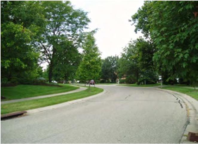
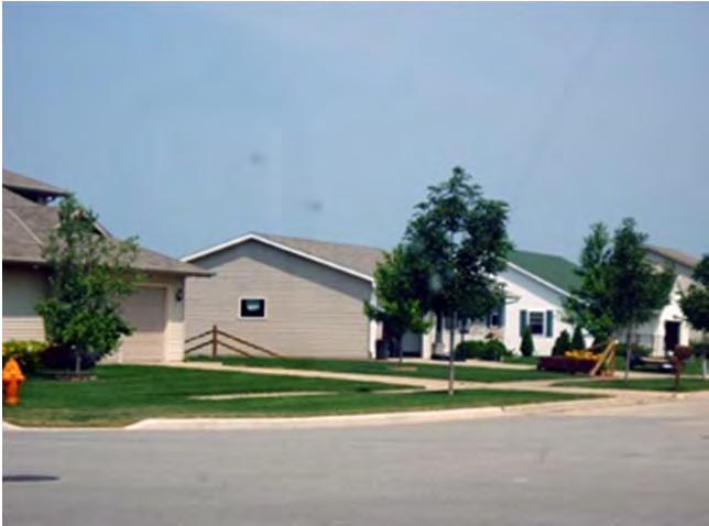
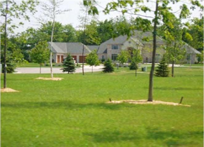
16 ABSORPTION Landscaping and vegetation can increase the challenge of reading a specific meter


17 ABSORPTION Water absorbs RF

18 ABSORPTION Environmental conditions change over time


19 ABSORPTION Temporary environmental changes may increase absorption


20 ABSORPTION Seasonal changes add or reduce absorbing vegetation


21 ABSORPTION Pine trees absorb more RF than leafy trees

22 ABSORPTION Fixed Networks have to consider the topography and it s impact on line of sight between endpoints and gateway.

23 ABSORPTION The endpoint on the left has LOS issues with both gateways. The endpoint on the right has LOS issues with one gateway but not the other.


24 OVERCOMING ABSORPTION Strive for clear line of sight between transmitter and receiver; minimize obstructions in RF path

25 OVERCOMING ABSORPTION Mount remote transmitter high in basement and near outer wall


26 OVERCOMING ABSORPTION Keep pit transmitter clear of dirt, grass and debris
27 SOME FACTORS AFFECTING LOS COMMUNICATIONS Free-space attenuation Absorption Reflection Diffraction Scattering Transmitter power Receiver sensitivity Antenna design and configuration

")
28 REFLECTION RF signal reflection occurs with variety of conducting (metal) objects

29 REFLECTION Chain link fences are reflective and can limit the RF signal passing through


30 REFLECTION Metal pit lids reflect RF inside the pit, which is then absorbed by the earth
31 Significant amount of radiated power is reflected back into the pit For network applications, endpoints need to be mounted through non-metal lids for optimal performance
32 REFLECTION METAL LIDS Even through the lid installations have significant interaction of the metal lid and the antenna, reducing radiated power
33 SIGNAL STRENGTH, OUTPUT POWER, AND PATH LOSS One primary cause of path loss is pit lids, here s an example of typical loss of various type s of pit lids based on their material: Type Loss Output Plastic -7 db +20 dbm Armorcast -10 db +17 dbm Concrete -14 db +13 dbm Metal Mesh -17 db +10 dbm Solid Metal -30 db -3 dbm Here is a comparison of the output powers of Itron endpoints: dbm Watts One watt endpoint +27 dbm 500 mw Don t forget, the new FN 100 will now have repeaters, which weren t available as well as faster bubble-up. 33
34 REFLECTION METAL LIDS Composite lids have no reflection and little absorption This is the preferred approach to fixed networks Absorption is still a factor, which is why endpoints should be mounted through the pit lid

35 REFLECTION Aluminum siding and flashing around the foundation is reflective, affecting basement transmitters

36 REFLECTION Vehicles cause reflections; some metal objects may be temporary while others may be permanent

37 REFLECTION While concrete exteriors will absorb, metal exteriors will reflect
38 SOME FACTORS AFFECTING LOS COMMUNICATIONS Free-space attenuation Absorption Reflection Diffraction Scattering Transmitter power Receiver sensitivity Antenna design and configuration
39 DIFFRACTION Radio waves can bend when they encounter a surface with sharp edges
40 SOME FACTORS AFFECTING LOS COMMUNICATIONS Free-space attenuation Absorption Reflection Diffraction Scattering Transmitter power Receiver sensitivity Antenna design and configuration
41 SCATTERING Radio waves are scattered when encountering particles such as rain or fog that are equal to or smaller than the wavelength of the signal


42 SCATTERING Fog, rain and snow cause scattering; absorption will also occur
43 SOME FACTORS AFFECTING LOS COMMUNICATIONS Free-space attenuation Absorption Reflection Diffraction Scattering Transmitter Power Receiver Sensitivity Antenna design and configuration
44 TRANSMITTERS AND RECEIVERS Endpoint power dictated by FCC, modern design concepts, and battery capacity Receiver sensitivity and signal-to-noise ratio determine if a signal can be heard Very low temperatures may have negative affect on receiver and endpoint performance due to effect on battery energy
45 SOME FACTORS AFFECTING LOS COMMUNICATIONS Free-space attenuation Absorption Reflection Diffraction Scattering Transmitter power Receiver sensitivity Antenna Design and Configuration

46 ANTENNA ORIENTATION Both transmitter and receiver antennas must be properly oriented with respect to each other to maximize energy transfer
47 OMNI-DIRECTIONAL ANTENNAS Omni-directional antennas are typical for AMR
48 DIRECTIONAL ANTENNAS Directional antennas typical in SCADA but not AMR


49 ANTENNA CONSIDERATIONS Separate multiple antennas as much as possible to avoid interaction

50 THE BOTTOM LINE It s difficult to predict RF paths
51 THE BOTTOM LINE RF transmission is influenced by many factors Specific applications will experience greater range while others will experience reduced range Conditions are continually changing
52 THE BOTTOM LINE Good installations will strive for a clear line of sight between endpoint and receiver Signals may still be received even though they are seriously degraded Multiple paths might either enhance the received signal or create a dead zone Maximum distance will vary for each transmitter/receiver combination
53 INSTALLATION TIPS Carefully follow installation instructions Try for a clear line of sight; locate endpoint to minimize obstructions Remote endpoint must be used in basement floor joists or on the outside of the building as alternative to an integral for basement applications
54 INSTALLATION TIPS Badger Meter requires that all Pit Endpoints be installed thruthe-lid using only non-metal lid (no integrals) for optimal performance
55 METER READING TIPS Systems will perform best when there is a clear line of sight between the gateway and the endpoint Two way systems may require additional infrastructure to ensure the communication to and from the endpoint is established Keep pit lids free of dirt, grass, debris
56 INTERFERENCE AND LICENSED VS. UNLICENSED Interference is going to happen on licensed and unlicensed channels. Unlicensed doesn t mean Unregulated. ORION has been designed to communicate across the ISM band to get reading data through if interference does occur. If you re licensed to a specific frequency and you have an issue with interference, you re stuck, you can t move. Additionally, the government still owns the frequency and is able to change the rules as needed. Licensed doesn t guarantee you won t have interference. 56
57 THANK YOU. 57
Data and Computer Communications Chapter 4 Transmission Media
 Data and Computer Communications Chapter 4 Transmission Media Ninth Edition by William Stallings Data and Computer Communications, Ninth Edition by William Stallings, (c) Pearson Education - Prentice Hall,
Antenna & Propagation. Basic Radio Wave Propagation
 For updated version, please click on http://ocw.ump.edu.my Antenna & Propagation Basic Radio Wave Propagation by Nor Hadzfizah Binti Mohd Radi Faculty of Electric & Electronics Engineering hadzfizah@ump.edu.my
Wireless Transmission Rab Nawaz Jadoon
 Wireless Transmission Rab Nawaz Jadoon DCS Assistant Professor COMSATS IIT, Abbottabad Pakistan COMSATS Institute of Information Technology Mobile Communication Frequency Spectrum Note: The figure shows
Unguided Transmission Media
 CS311 Data Communication Unguided Transmission Media by Dr. Manas Khatua Assistant Professor Dept. of CSE IIT Jodhpur E-mail: manaskhatua@iitj.ac.in Web: http://home.iitj.ac.in/~manaskhatua http://manaskhatua.github.io/
PRINCIPLES OF COMMUNICATION SYSTEMS. Lecture 1- Introduction Elements, Modulation, Demodulation, Frequency Spectrum
 PRINCIPLES OF COMMUNICATION SYSTEMS Lecture 1- Introduction Elements, Modulation, Demodulation, Frequency Spectrum Topic covered Introduction to subject Elements of Communication system Modulation General
Technician License Course Chapter 2 Radio and Signals Fundamentals
 Technician License Course Chapter 2 Radio and Signals Fundamentals Handling Large and Small Numbers Electronics and Radio use a large range of sizes, i.e., 0.000000000001 to 1000000000000. Scientific Notation
Chapter 1: Telecommunication Fundamentals
 Chapter 1: Telecommunication Fundamentals Block Diagram of a communication system Noise n(t) m(t) Information (base-band signal) Signal Processing Carrier Circuits s(t) Transmission Medium r(t) Signal
3C5 Telecommunications. what do radios look like? mobile phones. Linda Doyle CTVR The Telecommunications Research Centre
 3C5 Telecommunications what do radios look like? Linda Doyle CTVR The Telecommunications Research Centre ledoyle@tcd.ie Oriel/Dunlop House 2009 mobile phones talk is cheap.. bluetooth 3G WLAN/802.11 GSM
Section 1 Wireless Transmission
 Part : Wireless Communication! section : Wireless Transmission! Section : Digital modulation! Section : Multiplexing/Medium Access Control (MAC) Section Wireless Transmission Intro. to Wireless Transmission
Contents. ITS323: Introduction to Data Communications CSS331: Fundamentals of Data Communications. Transmission Media and Spectrum.
 2 ITS323: Introduction to Data Communications CSS331: Fundamentals of Data Communications Sirindhorn International Institute of Technology Thammasat University Prepared by Steven Gordon on 3 August 2015
ITS323: Introduction to Data Communications CSS331: Fundamentals of Data Communications
 ITS323: Introduction to Data Communications CSS331: Fundamentals of Data Communications Sirindhorn International Institute of Technology Thammasat University Prepared by Steven Gordon on 3 August 2015
Data and Computer Communications. Tenth Edition by William Stallings
 Data and Computer Communications Tenth Edition by William Stallings Data and Computer Communications, Tenth Edition by William Stallings, (c) Pearson Education - Prentice Hall, 2013 Wireless Transmission
Radio Propagation Fundamentals
 Radio Propagation Fundamentals Concept of Electromagnetic Wave Propagation Mechanisms Modes of Propagation Propagation Models Path Profiles Link Budget Fading Channels Electromagnetic (EM) Waves EM Wave
Wireless Communication Fundamentals Feb. 8, 2005
 Wireless Communication Fundamentals Feb. 8, 005 Dr. Chengzhi Li 1 Suggested Reading Chapter Wireless Communications by T. S. Rappaport, 001 (version ) Rayleigh Fading Channels in Mobile Digital Communication
What is a Communications System?
 Introduction to Communication Systems: An Overview James Flynn Sharlene Katz What is a Communications System? A communications system transfers an information bearing signal from a source to one or more
A bluffer s guide to Radar
 A bluffer s guide to Radar Andy French December 2009 We may produce at will, from a sending station, an electrical effect in any particular region of the globe; (with which) we may determine the relative
Vehicle Networks. Wireless communication basics. Univ.-Prof. Dr. Thomas Strang, Dipl.-Inform. Matthias Röckl
 Vehicle Networks Wireless communication basics Univ.-Prof. Dr. Thomas Strang, Dipl.-Inform. Matthias Röckl Outline Wireless Signal Propagation Electro-magnetic waves Signal impairments Attenuation Distortion
Antennas and Propagation
 CMPE 477 Wireless and Mobile Networks Lecture 3: Antennas and Propagation Antennas Propagation Modes Line of Sight Transmission Fading in the Mobile Environment Introduction An antenna is an electrical
Basic Radio Physics. Developed by Sebastian Buettrich. ItrainOnline MMTK 1
 Basic Radio Physics Developed by Sebastian Buettrich 1 Goals Understand radiation/waves used in wireless networking. Understand some basic principles of their behaviour. Apply this understanding to real
Antennas and Propagation. Chapter 5
 Antennas and Propagation Chapter 5 Introduction An antenna is an electrical conductor or system of conductors Transmission - radiates electromagnetic energy into space Reception - collects electromagnetic
Computer Networks Lecture -4- Transmission Media. Dr. Methaq Talib
 Computer Networks Lecture -4- Transmission Media Dr. Methaq Talib Transmission Media A transmission medium can be broadly defined as anything that can carry information from a source to a destination.
William Stallings Data and Computer Communications 7 th Edition. Chapter 4 Transmission Media
 William Stallings Data and Computer Communications 7 th Edition Chapter 4 Transmission Media Overview Guided - wire Unguided - wireless Characteristics and quality determined by medium and signal For guided,
Chapter 15: Radio-Wave Propagation
 Chapter 15: Radio-Wave Propagation MULTIPLE CHOICE 1. Radio waves were first predicted mathematically by: a. Armstrong c. Maxwell b. Hertz d. Marconi 2. Radio waves were first demonstrated experimentally
Antennas and Propagation
 Antennas and Propagation Chapter 5 Introduction An antenna is an electrical conductor or system of conductors Transmission - radiates electromagnetic energy into space Reception - collects electromagnetic
WIRELESS TRANSMISSION
 COMP 635: WIRELESS NETWORKS WIRELESS TRANSMISSION Jasleen Kaur Fall 205 Outline Frequenc Spectrum Ø Usage and Licensing Signals and Antennas Ø Propagation Characteristics Multipleing Ø Space, Frequenc,
Antennas and Propagation. Chapter 5
 Antennas and Propagation Chapter 5 Introduction An antenna is an electrical conductor or system of conductors Transmission - radiates electromagnetic energy into space Reception - collects electromagnetic
Wireless data networks Why is wireless different?
 Wireless data networks Why is wireless different? Martin Heusse X L ATEX E General info This is TLEN 5520, or ECEN 5032 ECCS 1B12, WF, 3:00pm to 4:15pm Please register to the class mailing list! send a
Antennas & Propagation. CSG 250 Fall 2007 Rajmohan Rajaraman
 Antennas & Propagation CSG 250 Fall 2007 Rajmohan Rajaraman Introduction An antenna is an electrical conductor or system of conductors o Transmission - radiates electromagnetic energy into space o Reception
Amateur Radio License. Propagation and Antennas
 Amateur Radio License Propagation and Antennas Todays Topics Propagation Antennas Propagation Modes Ground wave Low HF and below, ground acts as waveguide Line-of-Sight (LOS) VHF and above, radio waves
ELECTROMAGNETIC SPECTRUM ELECTROMAGNETIC SPECTRUM
 LECTURE:2 ELECTROMAGNETIC SPECTRUM ELECTROMAGNETIC SPECTRUM Electromagnetic waves: In an electromagnetic wave the electric and magnetic fields are mutually perpendicular. They are also both perpendicular
E-716-A Mobile Communications Systems. Lecture #2 Basic Concepts of Wireless Transmission (p1) Instructor: Dr. Ahmad El-Banna
 Instructor: Dr. Ahmad El-Banna") October 2014 Ahmad El-Banna Integrated Technical Education Cluster At AlAmeeria E-716-A Mobile Communications Systems Lecture #2 Basic Concepts of Wireless Transmission (p1) Instructor: Dr. Ahmad El-Banna
October 2014 Ahmad El-Banna Integrated Technical Education Cluster At AlAmeeria E-716-A Mobile Communications Systems Lecture #2 Basic Concepts of Wireless Transmission (p1) Instructor: Dr. Ahmad El-Banna
Antennas and Propagation
 Mobile Networks Module D-1 Antennas and Propagation 1. Introduction 2. Propagation modes 3. Line-of-sight transmission 4. Fading Slides adapted from Stallings, Wireless Communications & Networks, Second
Session2 Antennas and Propagation
 Wireless Communication Presented by Dr. Mahmoud Daneshvar Session2 Antennas and Propagation 1. Introduction Types of Anttenas Free space Propagation 2. Propagation modes 3. Transmission Problems 4. Fading
PROPAGATION MODELING 4C4
 PROPAGATION MODELING ledoyle@tcd.ie 4C4 http://ledoyle.wordpress.com/temp/ Classification Band Initials Frequency Range Characteristics Extremely low ELF < 300 Hz Infra low ILF 300 Hz - 3 khz Ground wave
Antenna Engineering Lecture 0: Introduction
 Antenna Engineering Lecture 0: Introduction ELCN405 Fall 2011 Communications and Computer Engineering Program Faculty of Engineering Cairo University 2 Outline 1 Electromagnetic Spectrum Recent Advances
UNIT Derive the fundamental equation for free space propagation?
 UNIT 8 1. Derive the fundamental equation for free space propagation? Fundamental Equation for Free Space Propagation Consider the transmitter power (P t ) radiated uniformly in all the directions (isotropic),
Chapter 3. Mobile Radio Propagation
 Chapter 3 Mobile Radio Propagation Based on the slides of Dr. Dharma P. Agrawal, University of Cincinnati and Dr. Andrea Goldsmith, Stanford University Propagation Mechanisms Outline Radio Propagation
Ad hoc and Sensor Networks Chapter 4: Physical layer. Holger Karl
 Ad hoc and Sensor Networks Chapter 4: Physical layer Holger Karl Goals of this chapter Get an understanding of the peculiarities of wireless communication Wireless channel as abstraction of these properties
Antenna Engineering Lecture 0: Introduction
 Antenna Engineering Lecture 0: Introduction ELC 405a Fall 2011 Department of Electronics and Communications Engineering Faculty of Engineering Cairo University 2 Outline 1 Why Study Antenna Engineering?
CS441 Mobile & Wireless Computing Communication Basics
 Department of Computer Science Southern Illinois University Carbondale CS441 Mobile & Wireless Computing Communication Basics Dr. Kemal Akkaya E-mail: kemal@cs.siu.edu Kemal Akkaya Mobile & Wireless Computing
Industrial Wireless Systems
 Application Considerations Don Pretty Principal Engineer Geometric Controls Inc Bethlehem, PA Sheet 1 Ethernet Dominates on the Plant Floor Sheet 2 Recognize Any of These? Sheet 3 Answers: 10 BASE 2 RG
4/18/2012. Supplement T3. 3 Exam Questions, 3 Groups. Amateur Radio Technician Class
 Amateur Radio Technician Class Element 2 Course Presentation ti ELEMENT 2 SUB-ELEMENTS Technician Licensing Class Supplement T3 Radio Wave Characteristics 3 Exam Questions, 3 Groups T1 - FCC Rules, descriptions
Mobile and Wireless Networks Course Instructor: Dr. Safdar Ali
 Mobile and Wireless Networks Course Instructor: Dr. Safdar Ali BOOKS Text Book: William Stallings, Wireless Communications and Networks, Pearson Hall, 2002. BOOKS Reference Books: Sumit Kasera, Nishit
Project = An Adventure : Wireless Networks. Lecture 4: More Physical Layer. What is an Antenna? Outline. Page 1
 Project = An Adventure 18-759: Wireless Networks Checkpoint 2 Checkpoint 1 Lecture 4: More Physical Layer You are here Done! Peter Steenkiste Departments of Computer Science and Electrical and Computer
Unguided Media and Matched Filter After this lecture, you will be able to Example?
 Unguided Media and Matched Filter After this lecture, you will be able to describe the physical and transmission characteristics of various unguided media Example? B.1 Unguided media Guided to unguided
3 Methods of radiocommunication
 + + & & * * ) ) From the ITU Emergency Telecommunications handbook; prepared for the 54 th JOTA 2011. 3 Methods of radiocommunication 3.1 Frequencies Radio frequencies should be selected according to propagation
Radio spectrum From Wikipedia, the free encyclopedia
 Page 1 of 13 Radio spectrum From Wikipedia, the free encyclopedia The radio spectrum is the part of the electromagnetic spectrum from 3 Hz to 3000 GHz (3 THz). Electromagnetic waves in this range, called
An Introduction to Electrical and Electronic Engineering Communication. Dr. Cahit Karakuş, 2018
 An Introduction to Electrical and Electronic Engineering Communication Dr. Cahit Karakuş, 2018 Significance of Human Communication Methods of communication: 1. Face to face 2. Signals 3. Written word (letters)
Chapter 1 Introduction
 Wireless Information Transmission System Lab. Chapter 1 Introduction National Sun Yat-sen University Table of Contents Elements of a Digital Communication System Communication Channels and Their Wire-line
Polarization orientation of the electric field vector with respect to the earth s surface (ground).
.") Free space propagation of electromagnetic waves is often called radio-frequency (rf) propagation or simply radio propagation. The earth s atmosphere, as medium introduces losses and impairments to the
Free space propagation of electromagnetic waves is often called radio-frequency (rf) propagation or simply radio propagation. The earth s atmosphere, as medium introduces losses and impairments to the
6 Radio and RF. 6.1 Introduction. Wavelength (m) Frequency (Hz) Unit 6: RF and Antennas 1. Radio waves. X-rays. Microwaves. Light
 Frequency (Hz) Unit 6: RF and Antennas 1. Radio waves. X-rays. Microwaves. Light") 6 Radio and RF Ref: http://www.asecuritysite.com/wireless/wireless06 6.1 Introduction The electromagnetic (EM) spectrum contains a wide range of electromagnetic waves, from radio waves up to X-rays (as
6 Radio and RF Ref: http://www.asecuritysite.com/wireless/wireless06 6.1 Introduction The electromagnetic (EM) spectrum contains a wide range of electromagnetic waves, from radio waves up to X-rays (as
An Introduction to Electrical and Electronic Engineering Electromagnetic. Dr. Cahit Karakuş, 2018
 An Introduction to Electrical and Electronic Engineering Electromagnetic Dr. Cahit Karakuş, 2018 Electromagnetic Spectrum Electromagnetic Spectrum Longest Wavelength Shortest Wavelength Electrical
Interpretation and Classification of P-Series Recommendations in ITU-R
 Int. J. Communications, Network and System Sciences, 2016, 9, 117-125 Published Online May 2016 in SciRes. http://www.scirp.org/journal/ijcns http://dx.doi.org/10.4236/ijcns.2016.95010 Interpretation and
Basic radio physics. Sebastian Büttrich, NSRC/ITU/wire.less.dk edit: June
 Basic radio physics Sebastian Büttrich, NSRC/ITU/wire.less.dk edit: June 2011 http://creativecommons.org/licenses/by-nc-sa/3.0/ Electromagnetic Fields Electromagnetic forces act between electric charges
Figure 4-1. Figure 4-2 Classes of Transmission Media
 Electromagnetic Spectrum Chapter 4 Transmission Media Computers and other telecommunication devices transmit signals in the form of electromagnetic energy, which can be in the form of electrical current,
Broad Principles of Propagation 4C4
 Broad Principles of Propagation ledoyle@tcd.ie 4C4 Starting at the start All wireless systems use spectrum, radiowaves, electromagnetic waves to function It is the fundamental and basic ingredient of
CHAPTER 6 THE WIRELESS CHANNEL
 CHAPTER 6 THE WIRELESS CHANNEL These slides are made available to faculty in PowerPoint form. Slides can be freely added, modified, and deleted to suit student needs. They represent substantial work on
Direct Link Communication II: Wireless Media. Motivation
 Direct Link Communication II: Wireless Media Motivation WLAN explosion cellular telephony: 3G/4G cellular providers/telcos in the mix self-organization by citizens for local access large-scale hot spots:
Elements of Communication System Channel Fig: 1: Block Diagram of Communication System Terminology in Communication System
 Content:- Fundamentals of Communication Engineering : Elements of a Communication System, Need of modulation, electromagnetic spectrum and typical applications, Unit V (Communication terminologies in communication
Supporting Network Planning Tools II
 Session 5.8 Supporting Network Planning Tools II Roland Götz LS telcom AG / Spectrocan 1 Modern Radio Network Planning Tools Radio Network Planning Tool Data / Result Output Data Management Network Processor
Radio Communication. Presentation created by: András Balogh
 Radio Communication Presentation created by: András Balogh AM and FM The goal is to transmit a modulating signal S(t) via a wave sin(ωt). In case of AM, the product of the modulation is f(t)=(a+s(t))*sin(ωt);
CS-435 spring semester Network Technology & Programming Laboratory. Stefanos Papadakis & Manolis Spanakis
 CS-435 spring semester 2016 Network Technology & Programming Laboratory University of Crete Computer Science Department Stefanos Papadakis & Manolis Spanakis CS-435 Lecture preview Wireless Networking
CSNT 180 Wireless Networking. Chapter 4 Radio Frequency (RF) Fundamentals for Wireless LAN Technology
 Fundamentals for Wireless LAN Technology") CSNT 180 Wireless Networking Chapter 4 Radio Frequency (RF) Fundamentals for Wireless LAN Technology Norman McEntire norman.mcentire@servin.com Founder, Servin Corporation, http://servin.com Technology
CSNT 180 Wireless Networking Chapter 4 Radio Frequency (RF) Fundamentals for Wireless LAN Technology Norman McEntire norman.mcentire@servin.com Founder, Servin Corporation, http://servin.com Technology
Class Overview. Antenna Fundamentals Repeaters Duplex and Simplex Nets and Frequencies Cool Radio Functions Review
 Class Overview Antenna Fundamentals Repeaters Duplex and Simplex Nets and Frequencies Cool Radio Functions Review Antennas Antennas An antenna is a device used for converting electrical currents into electromagnetic
CHAPTER 9 HIGH FREQUENCY RADIO OPERATION CHAPTER
 SECTION 2 ESTABLISHMENT, MAINTENANCE AND OPERATION OF COMMUNICATION SYSTEMS AND EQUIPMENT CHAPTER 9 HIGH FREQUENCY RADIO OPERATION CHAPTER 9 9.1 COMPLEXITIES AND VARIABLES The operation of High Frequency
Chapter 4: Transmission Media
 Chapter 4: Transmission Media Page 1 Overview Guided - wire Unguided - wireless Characteristics and quality determined by medium and signal For guided, the medium is more important For unguided, the bandwidth
CS311 -Data Communication Unguided Transmission Media
 CS311 -Data Communication Unguided Transmission Media Dr. Manas Khatua Assistant Professor Dept. of CSE IIT Jodhpur E-mail: manaskhatua@iitj.ac.in INTRODUCTION -Physical Path between transmitter and receiver
Maximum date rate=2hlog 2 V bits/sec. Maximum number of bits/sec=hlog 2 (1+S/N)
") Basics Data can be analog or digital. The term analog data refers to information that is continuous, digital data refers to information that has discrete states. Analog data take on continuous values.
Basics Data can be analog or digital. The term analog data refers to information that is continuous, digital data refers to information that has discrete states. Analog data take on continuous values.
Reading and working through Learn Networking Basics before this document will help you with some of the concepts used in wireless networks.
 Networking Learn Wireless Basics Introduction This document covers the basics of how wireless technology works, and how it is used to create networks. Wireless technology is used in many types of communication.
Outline / Wireless Networks and Applications Lecture 3: Physical Layer Signals, Modulation, Multiplexing. Cartoon View 1 A Wave of Energy
 Outline 18-452/18-750 Wireless Networks and Applications Lecture 3: Physical Layer Signals, Modulation, Multiplexing Peter Steenkiste Carnegie Mellon University Spring Semester 2017 http://www.cs.cmu.edu/~prs/wirelesss17/
Engr 1202 ECE. Clean Room Project
 Engr 1202 ECE Clean Room Project Dilbert the engineer gets special recognition September 2005 2014 Version does not even have my name! AC vs. DC Circuits DC and AC devices in everyday life DC Devices
Planning a Microwave Radio Link
 8000 Lee Highway Falls Church, VA 22042 703-205-0600 www.ydi.com Planning a Microwave Radio Link By Michael F. Young President and CTO YDI Wireless Background Most installers know that clear line of sight
Direct Link Communication II: Wireless Media. Current Trend
 Direct Link Communication II: Wireless Media Current Trend WLAN explosion (also called WiFi) took most by surprise cellular telephony: 3G/4G cellular providers/telcos/data in the same mix self-organization
Chapter-15. Communication systems -1 mark Questions
 Chapter-15 Communication systems -1 mark Questions 1) What are the three main units of a Communication System? 2) What is meant by Bandwidth of transmission? 3) What is a transducer? Give an example. 4)
Mobile Wireless Networking Physical Layer and Mobile Wireless Environment
 Mobile Wireless Networking The University of Kansas EECS 882 Physical Layer & MW Environment James P.G. Sterbenz Department of Electrical Engineering & Computer Science Information Technology & Telecommunications
Communications II. Mohammad Fathi Text book: J.G. Proakis and M. Salehi, Communication System Engineering (2 nd Ed) Syllabus
 Syllabus") Communications II Mohammad Fathi mfathi@uok.ac.ir Course information Text book: J.G. Proakis and M. Salehi, Communication System Engineering (2 nd Ed) Syllabus Introduction: [1.1, 1.2, 1.3, and 1.4] Review
Communications II Mohammad Fathi mfathi@uok.ac.ir Course information Text book: J.G. Proakis and M. Salehi, Communication System Engineering (2 nd Ed) Syllabus Introduction: [1.1, 1.2, 1.3, and 1.4] Review
Chapter 7 HF Propagation. Ionosphere Solar Effects Scatter and NVIS
 Chapter 7 HF Propagation Ionosphere Solar Effects Scatter and NVIS Ionosphere and Layers Radio Waves Bent by the Ionosphere Daily variation of Ionosphere Layers Ionospheric Reflection Conduction by electrons
Antennas and Propagation. Prelude to Chapter 4 Propagation
 Antennas and Propagation Prelude to Chapter 4 Propagation Introduction An antenna is an electrical conductor or system of conductors for: Transmission - radiates electromagnetic energy into space (involves
Antennas and Propagation Chapters T4, G7, G8 Antenna Fundamentals, More Antenna Types, Feed lines and Measurements, Propagation
 Antennas and Propagation Chapters T4, G7, G8 Antenna Fundamentals, More Antenna Types, Feed lines and Measurements, Propagation =============================================================== Antenna Fundamentals
Lesson 2: How Radio Works
 Lesson 2: How Radio Works Preparation for Amateur Radio Technician Class Exam Topics How radios work Current Frequency & Wavelength Radio Frequencies Quick review of Metric Electricity Conductors & Insulators
Sw earth Dw Direct wave GRw Ground reflected wave Sw Surface wave
 WAVE PROPAGATION By Marcel H. De Canck, ON5AU Electromagnetic radio waves can propagate in three different ways between the transmitter and the receiver. 1- Ground waves 2- Troposphere waves 3- Sky waves
Ham Radio Training. Level 1 Technician Level. Presented by Richard Bosch KJ4WBB
 Ham Radio Training Level 1 Technician Level Presented by Richard Bosch KJ4WBB In this chapter, you ll learn about: What is a radio signal The characteristics of radio signals How modulation adds information
Radar Reprinted from "Waves in Motion", McGourty and Rideout, RET 2005
 Radar Reprinted from "Waves in Motion", McGourty and Rideout, RET 2005 What is Radar? RADAR (Radio Detection And Ranging) is a way to detect and study far off targets by transmitting a radio pulse in the
Lesson 12: Signal Propagation
 Lesson 12: Signal Propagation Preparation for Amateur Radio Technician Class Exam Topics HF Propagation Ground-wave Sky-wave Ionospheric regions VHF/UHF Propagation Line-of-sight Tropospheric Bending and
Get Discount Coupons for your Coaching institute and FREE Study Material at COMMUNICATION SYSTEMS
 COMMUNICATION SYSTEMS 1. BASICS OF COMMUNICATION 2. AMPLITUDE MODULATION Get Discount Coupons for your Coaching institute and FREE Study Material at www.pickmycoaching.com 1 BASICS OF COMMUNICATION 1.
4/29/2012. General Class Element 3 Course Presentation. Radio Wave Propagation. Radio Wave Propagation. Radio Wave Propagation.
 General Class Element 3 Course Presentation ti ELEMENT 3 SUB ELEMENTS General Licensing Class Subelement G3 3 Exam Questions, 3 Groups G1 Commission s Rules G2 Operating Procedures G3 G4 Amateur Radio
Wireless Networked Systems. Lec #1b: PHY Basics
 Wireless Networked Systems CS 795/895 - Spring 2013 Lec #1b: PHY Basics Tamer Nadeem Dept. of Computer Science Wireless Communication Page 2 Spring 2013 CS 795/895 - Wireless Networked Systems Radio Signal
Technician License Course Chapter 4
 Technician License Course Chapter 4 Propagation, Basic Antennas, Feed lines & SWR K0NK 26 Jan 18 The Antenna System Antenna: Facilitates the sending of your signal to some distant station. Feed line: Connects
ITTC Mobile Wireless Networking The University of Kansas EECS 882 Physical Layer & MW Environment
 Mobile Wireless Networking The University of Kansas EECS 882 Physical Layer & MW Environment James P.G. Sterbenz Department of Electrical Engineering & Computer Science Information Technology & Telecommunications
So many wireless technologies Which is the right one for my application?
 So many wireless technologies Which is the right one for my application? Standards Certification Education & Training Publishing Conferences & Exhibits Don Dickinson 2013 ISA Water / Wastewater and Automatic
Chapter 13: Wave Propagation. EET-223: RF Communication Circuits Walter Lara
 Chapter 13: Wave Propagation EET-223: RF Communication Circuits Walter Lara Electrical to Electromagnetic Conversion Since the atmosphere is not a conductor of electrons (instead a good insulator), electrical
Basics of RFID technology Thomas Holtstiege Technical Manager EECC. October 2009
 Basics of RFID technology Thomas Holtstiege Technical Manager EECC October 2009 About the European EPC Competence Center (EECC) First European EPCglobal accredited performance test center Active since
CS263: Wireless Communications and Sensor Networks
 CS263: Wireless Communications and Sensor Networks Matt Welsh Lecture 3: Antennas, Propagation, and Spread Spectrum September 30, 2004 2004 Matt Welsh Harvard University 1 Today's Lecture Antennas and
Jeff Smith. DFW Plastics, Inc. Fort Worth, Texas
 Jeff Smith DFW Plastics, Inc. Fort Worth, Texas www.dfwplasticsinc.com There are many factors that may affect your RF performance within your AMR/AMI system. These are dependent on various areas within
Maximum Usable Frequency
 Maximum Usable Frequency 15 Frequency (MHz) 10 5 0 Maximum Usable Frequency Usable Frequency Window Lowest Usable Frequency Solar Flare 6 12 18 24 Time (Hours) Radio Blackout Usable Frequency Window Ken
Antenna Performance. Antenna Performance... 3 Gain... 4 Radio Power and the FCC... 6 Link Margin Calculations... 7 The Banner Way... 8 Glossary...
 Antenna Performance Antenna Performance... 3 Gain... 4 Radio Power and the FCC... 6 Link Margin Calculations... 7 The Banner Way... 8 Glossary... 9 06/15/07 135765 Introduction In this new age of wireless
(Refer Slide Time: 2:45)
") Millimeter Wave Technology. Professor Minal Kanti Mandal. Department of Electronics and Electrical Communication Engineering. Indian Institute of Technology, Kharagpur. Lecture-01. Introduction to Millimeter-Wave
Millimeter Wave Technology. Professor Minal Kanti Mandal. Department of Electronics and Electrical Communication Engineering. Indian Institute of Technology, Kharagpur. Lecture-01. Introduction to Millimeter-Wave
Determination of Propagation Path Loss and Contour Map for Adaba FM Radio Station in Akure Nigeria
 International Journal of Science and Technology Volume 2 No. 9, September, 2013 Determination of Propagation Path Loss and Contour Map for Adaba FM Radio Station in Akure Nigeria Oyetunji S. A, Alowolodu
Study of Factors which affect the Calculation of Co- Channel Interference in a Radio Link
 International Journal of Electronic and Electrical Engineering. ISSN 0974-2174 Volume 8, Number 2 (2015), pp. 103-111 International Research Publication House http://www.irphouse.com Study of Factors which
Intro to Radio Propagation,Antennas and Link Budget
 Intro to Radio Propagation,Antennas and Link Budget Training materials for wireless trainers Marco Zennaro and Ermanno Pietrosemoli T/ICT4D Laboratory ICTP Behavior of radio waves There are a few simple