A Shell construction
|
|
|
- Osborn Gardner
- 5 years ago
- Views:
Transcription
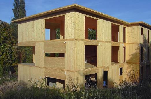
1 A Shell construction
2 A 4/2012 Content 1 BASE AND WALL ANCHORING 1.1 Base with mortar bed 1.2 Base with sill plate 1.3 Base with raised sill plate 1.4 Concrete base (mortar bed) 1.5 Concrete base (sill plate) 2 WALL JOINTS Basic design rules 2.1 Corner joint 2.2 T-joint 2.3 Horizontal wall joint (butt board) 2.4 Horizontal wall joint (butt jointing) 2.5 Horizontal wall joint (external butt boards) 2.6 Vertical wall joint (lap) 2.7 Vertical wall joint (butt board) 3 LINTELS 3.1 Continuous lintel 3.2 Engaged lintel 4 CEILING 4.1 Ceiling joint (butt board) 4.2 Ceiling joint (lap) 4.3 Ceiling joint (structural analysis, transverse tension) 4.4 Steel joist 4.5 Wooden joist 4.6 Joist (wall cut-out) 4.7 Joist (column) 4.8 Joist (beam holder) 4.9 Joist bearer 4.10 Wooden beam ceiling 4.11 Ribbed ceiling
3 A 4/ LOWER FLOOR WALL CEILING UPPER FLOOR WALL CONNECTION NODE 5.1 Platform framing 5.2 Balloon framing 6 ROOF 6.1 CLT roof structure (eaves laths) 6.2 CLT roof structure (butted against wall board) 6.3 CLT roof structure (birdsmouth joint) 6.4 Rafter roof (rafter cut-outs in the wall board) 6.5 Rafter roof (birdsmouth in rafter) 6.6 Ridge (with purlin) 6.7 Ridge (without purlin) in folded-plate structures 7 CANTILEVER/UPSTAND 7.1 Wooden upstand 7.2 Steel upstand 7.3 Wall as an upstand


4 1 Base and wall anchoring 1.1 Base with mortar bed seal against rising damp vertical seal wall anchoring foundation mortar bed The CLT board can be installed on a dry or wet mortar bed for tolerance compensation (full surface contact). The CLT must be protected against rising damp using a suitable damp-proof seal. When fitting the wall anchoring (tensile and shear forces), the permissible edge distances for the connectors must be observed.
 with.")
, the permissible edge distances for")
5 1.2 Base with sill plate vertical seal seal against rising damp wall anchoring foundation sill plate The must be sealed to the previously installed sill plate (e.g. larch) with. The sill plate in turn must be protected against damp rising from the foundation. When fitting the wall anchoring (tensile and shear forces), the permissible edge distances for the connectors must be observed.
 with.")

6 1.3 Base with raised sill plate vertical seal sill plate anchorage (according to structural analysis) seal against rising damp wall anchoring foundation sill plate The must be sealed to the previously installed sill plate (e.g. larch) with. The sill plate in turn must be protected against damp rising from the foundation. A raised sill plate enables a small but often necessary increase in the wall height from 2,950 mm to approx. 3,050 mm. When fitting the wall anchoring (tensile and shear forces), the permissible edge distances for the connectors must be observed.
. The CLT must be protected against rising damp using a suitable damp-proof seal.")
7 1.4 Concrete base (mortar bed) seal against rising damp wall anchoring vertical seal foundation mortar bed The CLT board can be installed on a dry or wet mortar bed for tolerance compensation (full surface contact). The CLT must be protected against rising damp using a suitable damp-proof seal. When fitting the wall anchoring (tensile and shear forces), the permissible edge distances for the connectors must be observed.
 with.")

8 1.5 Concrete base (sill plate) vertical seal sill plate anchorage (according to structural analysis) seal against rising damp wall anchoring foundation sill plate The must be sealed to the previously installed sill plate (e.g. larch) with. The sill plate in turn must be protected against damp rising from the foundation. In the case of wall anchorings, as shown in the picture on the left, please note that costs will be higher because of the horizontal and vertical loads that have to be absorbed. When screwing the CLT board to the sill plate, the permissible edge distances for the connectors must be observed.
9 2 Wall joints Basic design rules WALL JOINTS: 1. s should preferably be full-storey height (no joints). maximum wall height 2,950 mm (3,950 mm on request) CL Tw CL Tw all all bo bo a rd a rd 2. If the walls are higher than 2,950 mm or if extrawide boards (requiring special transport) are to be avoided, the wall boards can be joined vertically. (see details under 2.6 and 2.7) vertical wall joint 3. If alternatives 1 and 2 cannot be used, the boards must be joined horizontally. (see details under 2.3, 2.4 and 2.5) horizontal wall joint CL Tw CL Tw all all bo bo a rd a rd

 or in a")
10 2.1 Corner joint joint bonding with suitable adhesive tape (variant) To achieve the required airtightness in a building, the joints of the CLT boards can, apart from, alternatively be sealed with suitable adhesive tape on the inside and outside of the boards. The at the corner joint must be made either purely constructionally (screw at 90 ) or in a structurally effective way (slanted end-grain screwing).


11 2.2 T-joint (according to structural analysis) If the individual rooms in the building are required to be airtight, the joints of the CLT boards must be sealed with. The at the T-joint must be made either purely constructionally (screw at 90 ) or in a structurally effective way (slanted end-grain screwing).
 clearance butt board (second rebate may require double-sided machining) When using butt")

12 2.3 Horizontal wall joint (butt board) The joints shown have only limited torque rigidity! butt board clearance (according to structural analysis) clearance butt board (second rebate may require double-sided machining) When using butt boards (e.g. 3-layer board or laminated veneer lumber), the standard rebate dimensions of mm should preferably be ensured. Joint-sealing tape must be used to make the structure airtight. In the case of wall joints with rebated butt boards please note that the end-grain surface of the CLT boards becomes smaller as a result of the rebate (surface pressure).
 vertical wall post in the insulation layer (note risk of buckling) Joint-sealing tape must be")

13 2.4 Horizontal wall joint (butt jointing) (according to structural analysis) if required, also as an additional support for joists, rafters and purlins (surface pressure) vertical wall post in the insulation layer (note risk of buckling) Joint-sealing tape must be used to make the structure airtight. If positioned appropriately, an interior wall can also assume the function of the wall post shown in the drawing. The vertical wall post can serve as an additional support for, for example, joists or purlins (higher surface pressure).
14 2.5 Horizontal wall joint (external butt boards) butt board connection to wall board (nails, screws, staples), according to structural analysis When external butt boards are used (e.g. 3-layer plate or laminated veneer lumber), the subsequent layer structure must be adapted to them. Joint-sealing tape must be used to make the structure airtight. With this type of connection in particular the danger of buckling must be taken into account. The joint can also be adhesively bonded to enhance its rigidity.


15 2.6 Vertical wall joint (lap) clearance purely constructional when high shear force is transmitted at joint Joint-sealing tape must be used to make the structure airtight. The design must provide sufficient clearance (on one side), depending on the installation situation. If high shear force transmission at the joint cannot be avoided, the connectors must be specifically dimensioned and positioned as these forces require. Make allowance for in the rebate height, if necessary.


16 2.7 Vertical wall joint (butt board) clearance butt board When using butt boards (e.g. 3-layer board or laminated veneer lumber), the standard rebate dimensions of mm should preferably be ensured. Joint-sealing tape must be used to make the structure airtight. Instead of using screws, the butt board can be connected to the s with suitable glue which improves the transmission of the shear forces.
17 3 Lintels 3.1 Continuous lintel window opening sill height continuous lintel window opening If the lintel height is not sufficient from a structural engineering standpoint, there must be an appropriately dimensioned upstand from which the lintel can be suspended. If a wall above the lintel is used as an upstand, it is essential to take account of the sill height of any window openings. The lintel can be connected to the upstand (upper wall) with, for example, perforated metal plates or screws (end-grain screwing should be avoided in this case).
18 3.2 Engaged lintel window opening engaged lintel (glulam) window opening engaged lintel (CLT) An engaged lintel must be dimensioned according to the loads and forces acting on it. Attention must be paid to the surface pressure in the lintel support area. CLT lintels absorb and transmit shear forces significantly better than glulam lintels. This is because of the lack of transverse layers in glulam.


19


20 4 Ceiling 4.1 Ceiling joint (butt board) clearance butt board fastenings When using butt boards at ceiling joints (e.g. OSB, 3-layer board or laminated veneer lumber), the standard rebate dimensions of mm should preferably be ensured. Joint-sealing tape must be used if necessary to make the connection airtight. Appropriately sized nails, screws or staples can be used as connectors (note permissible minimum diameter).


21 4.2 Ceiling joint (lap) clearance clearance under high shear flow Joint-sealing tape must be used if necessary to make the connection airtight. The design must provide sufficient clearance (on one side), depending on the installation situation. If high shear flow can be expected at the joint, the connectors must be dimensioned and positioned accordingly.
22 4.3 Ceiling joint (structural analysis, transverse tension) clearance static system: clearance to increase transverse tension for shear force transmission at the joint static system:


23 joist to joist to increase transverse tension Joint-sealing tape must be used if necessary to make the connection airtight. The design must provide sufficient clearance, depending on the installation situation. Depending on the static system, fully threaded screws must be used in order to secure effective lateral force connections at the joint and the point of support.
24 4.4 Steel joist steel girder as a joist (under the ceiling) (clearance to steel girder) steel girder as a joist (rebated at top and bottom) (according to structural analysis) (clearance to steel girder) gypsum cardboard / gypsum fibreboard steel girder as a joist (rebated at bottom, not rebated at top)
 Joint-sealing tape must be inserted or other tape bonded if")

25 (clearance to steel girder) steel girder as a joist (rebated at top and bottom) depending on rebate dimensions or to protect against transverse tension derived timber board (joist cladding) Joint-sealing tape must be inserted or other tape bonded if necessary to make the connection airtight. To ensure trouble-free assembly, s must have sufficient clearance because of the cross-section of steel girders. In the case of specific fire protection requirements, metal joists must be clad or coated with special paint.
 joist (glulam)")

26 4.5 Wooden joist joist (glulam) joist (glulam) Joint-sealing tape must be used if necessary to make the connection airtight.
 A suitable adhesive tape (joint bonding) must be used if necessary to make the")

27 4.6 Joist (wall cut-out) suitable adhesive tape (airtight) clearance joist (glulam) reinforce support, if necessary (surface pressure) A suitable adhesive tape (joint bonding) must be used if necessary to make the structure airtight. The design must provide sufficient clearance, depending on the installation situation. If necessary, the support surface in the wall board must be reinforced with a metal plate and fully threaded screws (pressure).
 joist (glulam) column (joist")

28 4.7 Joist (column) (according to structural analysis) joist (glulam) column (joist support) The design must provide sufficient clearance, depending on the installation situation.
29 4.8 Joist (beam holder) slotted plate and dowel pins joist (glulam) The design must provide sufficient clearance, depending on the installation situation.


30 joist fastened with concealed beam holder joist (glulam) The design must provide sufficient clearance, depending on the installation situation. Appropriate beam holders must be used which correspond to the dimensions of the joists.
31 4.9 Joist bearer joist bearer further ceiling structure ceiling beam rebate (preserving middle layer) joist bearer further ceiling structure ceiling beam Joint-sealing tape must be used if necessary to make the connection airtight. To ensure airtightness of the, it is essential to preserve its middle layer (rebate area). Please note: Rebating reduces the support surface at the joint; additionally, the joist bearer can shrink, which would make load transfer impossible (surface pressure).


32
 of the")

33 4.10 Wooden beam ceiling ceiling beam (glulam) Deflection (serviceability check) of the ceiling board must be taken into account (centre distance of the beams and dimensions of the ceiling).
.")
 can be included in the structural")
34 4.11 Ribbed ceiling rib (glulam) Deflection (serviceability check) of the ceiling board must be taken into account (centre distance of the ribs and dimensions of the ceiling). Structural connection between the ribs and ceiling by means of screwing or gluing. Ceiling (with span direction parallel to that of the ribs) can be included in the structural analysis or can be estimated.
 joint bonding with suitable adhesive tape (variant) wall-to-ceiling wall")

35 5 Lower floor wall ceiling upper floor wall connection node 5.1 Platform framing of T-joint (according to structural analysis) joint bonding with suitable adhesive tape (variant) wall-to-ceiling wall anchoring To achieve the required airtightness in a building, the joints of the CLT boards can, apart from, alternatively be sealed with suitable adhesive tape on the inside and outside of the boards. Wall anchoring for structurally effective connection between wall and ceiling (shear and tensile forces). Screw connection of T-joint from inside or outside.


36 wall-to-ceiling joint bonding with suitable adhesive tape (variant) wall anchoring To achieve the required airtightness in a building, the joints of the CLT boards can, apart from, alternatively be sealed with suitable adhesive tape on the inside and outside of the boards. Wall anchoring for structurally effective connection between wall and ceiling (shear forces in wall direction; tensile and compressive forces from wind load).
 In the case of specific fire protection requirements, the angle bracket on which the ceiling board rests must be clad.")
37 5.2 Balloon framing clearance angle bracket as a support (rating according to structural analysis) joint-sealing tape angle bracket as a support (rating according to structural analysis) In the case of specific fire protection requirements, the angle bracket on which the ceiling board rests must be clad.
 CLT roof board eaves lath Joint-sealing")

38 6 Roof 6.1 CLT roof structure (eaves laths) CLT roof board eaves lath Joint-sealing tape must be used to make the structure airtight. Note edge distances of. The between the roof and wall boards absorbs shear forces acting in the direction of the point of support and suction forces from the wind load.

39 6.2 CLT roof structure (butted against wall board) CLT roof board Joint-sealing tape must be used to make the structure airtight. Only the needs a bevelled edge, with the CLT roof board forming the roof projection and soffit. The between the roof and wall boards absorbs shear forces acting in the direction of the point of support and suction forces from the wind load.

.")
40 6.3 CLT roof structure (birdsmouth joint) CLT roof board Joint-sealing tape must be used to make the structure airtight. The has a straight edge requiring a birdsmouth to be machined in the roof board (please note that the birdsmouth must not be too deep, otherwise it might weaken the lower longitudinal layer). The between the roof and wall boards absorbs shear forces acting in the direction of the point of support and suction forces from the wind load.
 rafter Sufficient clearance must be provided in the rafter cut-outs in the wall.")

41 6.4 Rafter roof (rafter cut-outs in the wall board) clearance (according to structural analysis) rafter Sufficient clearance must be provided in the rafter cut-outs in the wall. Depending on requirements, or exterior adhesive tape must be used to make the structure airtight. The between the rafters and CLT wall board absorbs the suction forces of the wind.


42 6.5 Rafter roof (birdsmouth in rafter) (according to structural analysis) rafter purlin extension When purlin extensions are attached, they must reach at least as far as the first rafter inside the gable wall. Depending on requirements, or exterior adhesive tape must be used to make the structure airtight. The between the rafters and CLT wall board or purlin extension absorbs the suction forces of the wind.
.")
43 6.6 Ridge (with purlin) ridge purlin clearance (between CLT roof boards) CLT roof board The prescribed support point widths and areas must be observed. Ensure that the birdsmouth is sufficiently deep, based on the structure of the roof board (number of layers). Joint-sealing tape must be used to make the structure airtight.
 (according to structural analysis) CLT roof board CLT roof board")

44 6.7 Ridge (without purlin) in folded-plate structures (according to structural analysis) (according to structural analysis) CLT roof board CLT roof board Joint-sealing tape must be used to make the structure airtight. The roof is fitted with the aid of falsework. In this case, the of the CLT roof boards can mainly absorb and transmit shear forces.
45 7 Cantilever/upstand 7.1 Wooden upstand upstand (glulam) The between the ceiling boards and the upstand depends on the forces acting. The choice is between fully threaded screws and partly threaded flat-head screws. When using partly threaded flat-head screws ensure that the head is buried.
46 7.2 Steel upstand upstand (steel girder) In this case, fully threaded and partly headed screws can be used for the. As the screwing is carried out from above, steel beams of low cross-sectional height must be provided with holes in the upper flange (through which screws can be inserted).
47 7.3 Wall as an upstand wall functions as an upstand sill he igh t Please note: If the wall has a window opening in this position, it can no longer be used as a cantilever and a support for other walls. metal plate (reinforcement of support point) When using upper-floor wall boards as upstands (for attaching the ceiling above), window openings and their sill height must be taken into account. Use metal plates and fully threaded screws to transmit forces from end grain to end grain (pressure). Cantilever ceilings must be connected to upper wall boards with closely spaced, fully threaded screws.


48
CROS S L A MINAT ED TIMBER S TRUCTURES
 M a d e f o r b u i l d i n g b u i l t f o r l i v i n g COMP onent CATA LO GUE FOR CROS S L A MINAT ED TIMBER S TRUCTURES I M P R I N T KLH Massivholz GmbH Publisher and responsible for the content:
Sections & Details VOCABULARY
 1 Sections & Details VOCABULARY 1 ROOF FRAMING DETAIL RIDGE BOARD SHEATHING SHINGLES WEB FASCIA RAFTER (chord) SOFFIT SHEATHING STUD INSULATION DOUBLE TOP PLATE CEILING JOIST 2 FOUNDATION DETAIL STUD SHEATHING
GLOSSARY OF TERMS SECTION 8
 GLOSSARY OF TERMS SECTION 8 Anchor Bolt Angle Base Plate Bay Blocking CCB Centerline Chord Cladding Clip Closure Strip An A-307 steel bolt embedded in the concrete footing to anchor the base plate of the
3. Are component and cladding design pressures consistent with ASCE 7 for the wind speed and exposure category (ASCE 7 Fig. 6-3)?
?") Mobile County Public Works Residential Plan Reviewers Checklist For Structural Requirements of Wood Framed Residences Recommendation: Permit as Noted Revise Plans and Resubmit MCPW Ref. No. Design Criteria:
Mobile County Public Works Residential Plan Reviewers Checklist For Structural Requirements of Wood Framed Residences Recommendation: Permit as Noted Revise Plans and Resubmit MCPW Ref. No. Design Criteria:
Introducing AJSTM INSTALLATION GUIDE USA. 8 th Edition USA
 The SIMPLE FRAMING SYSTEMSM INSTALLATION GUIDE USA for Floors This Installation Guide is intended to provide general information for the designer and end-user. For further information, please refer to
Sections & Details. WOOD SILL and FLOOR CONSTRUCTION NOTES
 2 Sections & Details WOOD SILL and FLOOR CONSTRUCTION NOTES 1 Commonly Used Lumber Common LENGTHS include: 8, 10, 12, 14, 16 NOMINAL SIZES 2 x 4 2 x 6 2 x 8 2 x 10 2 x 12 ACTUAL SIZES 1 ½ x 3 ½ 1 ½ x 5
Intex Engineered Pergola System Installation Instructions. NOTE: See Appendix for Foundation Requirements
 Intex Engineered Pergola System Installation Instructions NOTE: See Appendix for Foundation Requirements Pergola Installation, Freestanding (If pergola will be attached-to-structure, skip to page 3) 1.
eb^sv=qfj_bo UNIVERSITY OF WISCONSIN - STOUT COLLEGE OF SCIENCE TECHNOLOGY ENGINEERING & MATHEMATICS Architectural Technology AEC 233
 eb^sv=qfj_bo UNIVERSITY OF WISCONSIN - STOUT COLLEGE OF SCIENCE TECHNOLOGY ENGINEERING & MATHEMATICS Architectural Technology AEC 233 Dr. Jason E. Charalambides fkqolar`qflk Heavy timber construction consists
Butt Two pieces of wood meeting with flat sides adjoining usually at right angles. Some type of connector is needed to prevent movement.
 Wood Connections There are basically five different types of connectors: Interlocking (carpentry joints), Dowel, Metal Connectors, Special Formed Connectors and Adhesives. I Interlocking (Carpentry Joints)
HECO-TOPIX -CombiConnect HECO-TOPIX -Therm HCS-Calculation software
 HECO-TOPIX -CombiConnect HECO-TOPIX -Therm HCS-Calculation software THE WOOD SCREW FOR THE PROFESSIONAL The HECO-Calculation software (HCS) and HECO-TOPIX Woodscrews for easy estimation and safe assembling
nineteen Wood Construction 1 and design APPLIED ARCHITECTURAL STRUCTURES: DR. ANNE NICHOLS FALL 2016 lecture STRUCTURAL ANALYSIS AND SYSTEMS ARCH 631
 APPLIED ARCHITECTURAL STRUCTURES: STRUCTURAL ANALYSIS AND SYSTEMS DR. ANNE NICHOLS FALL 2016 lecture nineteen wood construction and design Wood Construction 1 Timber Construction all-wood framing systems
Acceptable Standards of Domestic Construction
 Truss or Rafter Roof Batten Triple grip fastener (for roof trusses) Foil lined Insulation blanket Top plate Sprocket Brick tie Top plate strapping at 1200mm max. cts. Note: Holding down straps should be
THE ENGINEERED WOOD ASSOCIATION
 D A T A F I L E APA Performance Rated Rim Boards A rim board is the wood component that fills the space between the sill plate and bottom plate of a wall or, in second floor construction, between the top
Clopay Models 835/837 Sliding Door System Installation Guide
 Clopay Models 835/837 Sliding Door System Installation Guide The aim of this instruction is to guide you through the process of construction and fitting of Sliding Doors. Due to the number of sizes available
Wood structures Copyright G G Schierle, press Esc to end, for next, for previous slide 1
 Wood structures Copyright G G Schierle, 2001-02 press Esc to end, for next, for previous slide 1 Wood Types: Balloon framing (rare) Platform framing Heavy timber framing Advantages: The only renewable
FASTENERS BUILDING DEPARTMENT
 FASTENERS BUILDING DEPARTMENT 952-446-1660 WWW.CITYOFMINNETRISTA.COM This handout is intended only as a guide and is based in part on the 2015 Minnesota Residential Code, Minnetrista City ordinances, and
Production Technology woodtec Fankhauser GmbH Timber Frame + swiss quality Construction Table The Modular System for Timber Frames
 woodtec Fankhauser GmbH Production Technology For Timber Frame Timber Frame + swiss quality Construction Table The Modular System for Timber Frames 2 woodtec Fankhauser The modules are only mechanically
Joshua Woodsman
 CONSTRUCTION GUIDE of one of our design Please Note This electronic document is protected by the identifier against unauthorized dissemination on the Internet. Before building any structure make sure you
Glulam Connection Details
 T E C H N I C A L N O T E Glulam Connection Details Note: This version is superseded by a more current edition. Check the current edition for updated design and application recommendations. ENGINEERED
WOODEN BUILDINGS 6.1 INTRODUCTION 6.2 TYPICAL DAMAGE AND FAILURE OF WOODEN BUILDINGS. Chapter 6
 Chapter 6 WOODEN BUILDINGS 6.1 INTRODUCTION Wood has higher strength per unit weight and is, therefore, very suitable for earthquake resistant construction. But heavy cladding walls could impose high lateral
Drywall, Wood and Truss Uplift
 Drywall, Wood and Truss Uplift Drywall (gypsum board) has to: provide rigidity provide aesthetics provide fire protection not leak air Concerns Wood moves. Drywall does not move. Interesting problem. The
MAT105: Floor Framing
 MAT105: Copyright 2007 American Forest & Paper Association, Inc. Because the common applications for wood framing are in residential construction, the details of this program will be based on the IRC which
General Layout. Eng. Maha Moddather
 General Layout Eng. Maha Moddather mahamoddather@eng.cu.edu.eg Introduction Concrete Beam subjected to Bending Moment around Major Axis M x Compression d Concrete tensile strength is neglected A S Tension
GlasRoc Sheathing Type X
 Wall / Fire-Rated Systems 3-5/8" (92 mm) Steel Studs ProRoc Steel Stud System 3-5/8" (92 mm) Steel Track 3-1/2" (89 mm) Glass Fiber or Mineral Wool Insulation GlasRoc Sheathing Type X UL Design U465 Cavity
APA Performance Rated Rim Boards
 D a t a F i l e APA Performance Rated Rim Boards A Rim Board is the wood component that fills the space between the sill plate and bottom plate of a wall or, in second floor construction, between the top
How to Build Good Decks..
 How to Build Good Decks.. Worldwide Sleeping Company, Inc Cary, North Carolina Decking Overview.. Decking Overview.. more Decking Joist.... Joist Hanger Ledger Lag Screw House Wall Decking House Floor
The better way to build TM. Installation Manual ROOF SIPs
 The better way to build TM Installation Manual ROOF SIPs August 2017 ROOF SIPs Installation Manual Table of Contents Topics General Requirements.................................... 3 Materials..............................................
Fastener Schedule. a, b, c. FASTENER Roof 3-8d (2 1 / ) / ) 3-10d. 3-10d ( ) 3-16d box nails. (3 1 2 toe nails on one side
 / ) 3-10d. 3-10d ( ) 3-16d box nails. (3 1 2 toe nails on one side") ITEM 1 DESCRIPTION OF BUILDING ELEMENTS Blocking between joists or rafters to top plate, toe 2 Ceiling joists to plate, toe 3 4 5 6 Ceiling joists not attached to parallel rafter, laps over partitions,
ITEM 1 DESCRIPTION OF BUILDING ELEMENTS Blocking between joists or rafters to top plate, toe 2 Ceiling joists to plate, toe 3 4 5 6 Ceiling joists not attached to parallel rafter, laps over partitions,
ROOF-CEILING CONSTRUCTION
 CHAPTER 8 ROOF-CEILING CONSTRUCTION SECTION R801 GENERAL R801.1 Application. The provisions of this chapter shall control the design and construction of the roof-ceiling system for all buildings. R801.2
3.1 General Provisions
 WOOD FRAME CONSTRUCTION MANUAL 107 3.1 General Provisions 3.1.1 Prescriptive Requirements The provisions of this Chapter establish a specific set of resistance requirements for buildings meeting the scope
LVL8 H1.2 GENERAL FRAMING. Eco Friendly Revolutionary H1.2 Treatment Azotek by Zelam
 LVL8 H1.2 GENERAL FRAMING Eco Friendly Revolutionary H1.2 Treatment Azotek by Zelam NPIL/MARCH2015 Introduction to NelsonPine LVL8 H1.2 NelsonPine LVL is an engineered wood composite made from rotary peeled
BRACING BRACING SECTION 7 SECTION 7
 If we are to learn from the past, it is clear that there is generally a lack of understanding of the purpose of roof bracing and who should be responsible for it. This has led to disputes, claims and,
BauBuche Fasteners and connections
 BauBuche Fasteners and connections Beech laminated veneer lumber Chapter under revision 05 BauBuche Fasteners and connections 05 04-18 - EN Sheet 1 / 10 Fasteners and connections Sheet CONTENTS 2 3 4 9
GIRTS ON BACK OF BUILDING
 GIRTS ON BACK OF BUILDING ALL GIRTS ARE 1 1/2 SQUARE TUBE. GIRT LENGTHS FOR 12, 20, 24, AND 30 WIDE BUILDINGS: ON 12 WIDE BUILDINGS GIRTS ARE 67 3/4 LONG ON 20 WIDE BUILDINGS GIRTS ARE 56 3/4 LONG ON 24
How-To-build guide Garden shed
 How-To-build guide Garden shed What you can build using this guide This guide will show you how to build a re-locatable garden shed. Before you begin building Contact your local territorial authority to
The WANZ Guide to Window Installation
 The WANZ Guide to Window Installation as described in E2/AS1 Amendment 5 1 October 2012 Ver. 1.2 Window Association of New Zealand Page 2 of 74 Contents Overview Page 5 Objective Page 5 Scope Page 5 Opening
SuperFOIL Insulation. Solutions Guide. Pitched Roof - Under Rafter
 SuperFOIL Insulation Solutions Guide Pitched Roof - Under Rafter SF19+ Pitched Roof Under Rafter Solutions CONSTRUCTION THICKNESS R -VALUE EXTERNAL SURFACE - 0.040 TILES / SLATES 10mm - BATTEN CAVITY 25mm
Expressed Hardwood Structures
 Expressed Hardwood Structures Introduction This guide provides ideas and design information to assist in the development of expressed native timber structures in buildings. Basic information on how to
BUILDING THE BASIC SHED. Step A: Build the Foundation & Floor Frame
 BUILDING THE BASIC SHED Step A: Build the Foundation & Floor Frame 1. Excavate the building site and add a 4" layer of compactible gravel. If desired, add an extension to the base for the optional wood
Core Curriculum Carpentry 1 Carpentry 2 Carpentry 3
 A Correlation of Core Curriculum Carpentry 1 Carpentry 3 To the Carpentry II Course Standards and Objectives to the Content Standards Resource Title: Core Curriculum: Introductory Craft Skills, Fifth Edition
HOME STRENGTHENING GUIDE HOW TO ECONOMICALLY STRENGTHEN YOUR HOUSE AGAINST EARTHQUAKES AND HURRICANES
 HOME STRENGTHENING GUIDE HOW TO ECONOMICALLY STRENGTHEN YOUR HOUSE AGAINST EARTHQUAKES AND HURRICANES Grenville W Phillips II BSc, BEng, MASc, MURP, CEng, FIStructE, FCIHT, MAPM, MCSCE, MBAPE Chartered
F I X I N G B R O C H U R E
 F I X I N G B R O C H U R E Joist Hangers Joist Hangers on Steel Beams Fixing Masonry Hangers Speedy Joist Hangers Lateral Restraint Straps Roof Tie Down Straps Herring Bone Joist Strut Bat 'U' Nail Plate
INSTALLATION SHOP DRAWINGS FOR MINNEAPOLIS, MN
 MINNEAPOLIS, MN 2-0- 2-- General Notes Abbreviations Deviations from Architectural Specifications Deviations from Architectural Drawings ALUM. = ALUMINUM B.O. = BY OTHERS CONT. = CONTINUOUS. = CLEARANCE
STRUCTURAL TIMBER DESIGN
 STRUCTURAL TIMBER DESIGN to Eurocode 5 2nd Edition Jack Porteous BSc, MSc, DIC, PhD, CEng, MIStructE, FICE Director lack Porteous Consultancy and Abdy Kernlani BSc, MSc, PhD, CEng, FIStructE, FIWSc Professor
A. Rough carpentry includes but is not limited to the following:
 SECTION 06100 ROUGH CARPENTRY PART 1 - GENERAL 1.01 RELATED DOCUMENTS A. Drawings and general provisions of Contract, including General and Supplementary Conditions and Division-1 Specification Sections,
Installation guide for 20/20
 Introduction The following installation instructions are recommended minimum requirements for the 20/20. The designer and fixer should ensure that tiles are installed in accordance with BS 5534; The British
MAGNUM BOARD INTERIOR INSTALLATION GUIDELINES
 TECHNICAL BULLETIN No.: 090509-1405 Subject: Issue Date: September 4, 2009 Issue No.: II MAGNUM BOARD INTERIOR INSTALLATION GUIDELINES 1. CUTTING MAGNUM BOARD You can easily cut Magnum Board with carbide
Appendix C: Cheat Sheets Construction Manual
 Appendix C: Cheat Sheets Construction Topic Section Reference Nails Not Applicable Lumber Not Applicable Cap Plate 4.2.10 Mud Sill Anchors 4.5.1 HVAC 4.5.4 Attic Access 4.5.5 Deadwood 4.5.6 Blocking 4.5.7,
Shingle Installation Guide
 Installation Guide Roof Framing Information Installation Installation Accessory Installation Estimating Data General Information Roof Framing Information It is the responsibility or roofers, building contractors
Strands & Standards CARPENTRY 2
 Strands & Standards CARPENTRY 2 COURSE DESCRIPTION This is the second in a sequence of courses that prepares individuals to layout, fabricate, erect, install, and repair wooden structures and fixtures
Fibre Cement G C. Batten Fixing Setout ST-01. Jan 2014 A4 PROFILE DATE SCALE DETAIL DETAIL NO. Plank joint. 600mm stud crs.
 Plank joint 600mm stud crs 600mm 600mm 600mm Horizontal Structural Timber Cavity atten 50x20mm H3.1 atten fixing points 800mm 800mm 300mm 800mm Max. Nog spacing 50mm All intermediate battens to be 50x20mm
VERSA-LAM. An Introduction to VERSA-LAM Products
 44 VERSA-LAM An Introduction to VERSA-LAM Products VERSA-LAM is one of the strongest and stiffest engineered wood products approved in the UK. 241 302 356 406 VERSA-LAM products are excellent as floor
COLUMN 11/2013 LINEAR STRUCTURAL ELEMENT
 11/2013 LINEAR STRUCTURAL ELEMENT OÜ TMB Element produces linear structural elements with the product name column in conformity with the standard EVS-EN 13225 Precast concrete products. Linear structural
Site Installation Guide
 Site Installation Guide Site Checklist Stop and read this now. Tick box when checked. Floor Joist Layout If a floor joist design/layout was done, was a site copy of the layout provided with the joists,
With Illustrations, Drawings & Step By Step Details. Click Here To Download 12,000 Shed Plans. 1 P a g e Download 12,000 More Shed Plans
 With Illustrations, Drawings & Step By Step Details Click Here To Download 12,000 Shed Plans 1 P a g e Download 12,000 More Shed Plans Table of Contents OVERVIEW... 3 MATERIALS & CUTTING LISTS... 4 DRAWINGS,
With Illustrations, Blueprints & Step By Step Details Brought To You By ShedPlansz.Com Click Here To Get More Shed Plans
 12 X 8 Shed Plans With Illustrations, Blueprints & Step By Step Details Brought To You By ShedPlansz.Com Click Here To Get More Shed Plans Blueprints And Diagrams Instructions For Building The Shed
SECTION ROUGH CARPENTRY
 SECTION 06100 PART I - GENERAL 1.01 DESCRIPTION A. Scope: Work of this Section shall include all materials and installation necessary to provide Rough Carpentry as shown and detailed on the Drawings and
Timber to Timber - Timber to Concrete - Timber to Steel
 01/2017 TIMBER CONNECTORS NOT TO BE USED IN EXTERIOR SITUATIONS Stainless Steel alternatives are available where stated Timber to Timber - Timber to Concrete - Timber to Steel MiTek manufactures and markets
Wood Connections. Presented by: Karyn Beebe, P.E.
 Wood Connections Presented by: Karyn Beebe, P.E. Key to Connections 1. Wood has a strong and weak direction 2. Wood Moves 3. Strive for Consistency 4. Wood and Moisture Don t Mix 5. Load Path Continuity
Chapter 51: Sidewall Overhang(s) Only - Enclosed
 Only - Enclosed") Chapter 51: Sidewall Overhang(s) Only - Enclosed Most Common Mistakes: 1. Incorrect eave height. 2. Placing eave girt below truss tails. 3. Fascia board top edges not bevel cut to match roof slope. 4.
Chapter 51: Sidewall Overhang(s) Only - Enclosed Most Common Mistakes: 1. Incorrect eave height. 2. Placing eave girt below truss tails. 3. Fascia board top edges not bevel cut to match roof slope. 4.
10x10 Shed Plans and Building Guide
 Page 1 Legal 2018 Zac Spade & Christopher D. Brown. All Rights Reserved For information about special discounts available for bulk purchases, sales promotions, fundraising and educational needs, contact
8 x 10 Timber-frame Garden Shed
 8 x 10 Timber-frame Garden Shed Includes: Step-By-Step Instructions, Complete Details & Materials Lists Timber-framing is a traditional building method that uses a simple framework of heavy timber posts
SAMPLE INSTRUCTIONS. Best Barns USA Assembly Book. the North Dakota with pocket doors. Building Size 12'x12' or 12'x16' Revised August 30, 2011
 Best Barns USA Assembly Book Revised August 30, 2011 SAMPLE INSTRUCTIONS the North Dakota with pocket doors Building Size 12'x12' or 12'x16' Manufactured by Reynolds Building Systems, Inc. 205 Arlington
DUTCH GABLE FREESTANDING CARPORT
 DUTCH GABLE FREESTANDING CARPORT STRATCO OUTBACK ASSEMBLY INSTRUCTIONS. Your complete guide to building a FREESTANDING Outback DUTCH GABLE CARPORT BEFORE YOU START Carefully read these instructions. If
The Complete Guide to Building with Green Mountain Panels
 The Complete Guide to Building with s The Complete Guide to Building with s 74 Glen Orne Drive Brattleboro, VT 05301 (800) 882-9490 (802) 254-3435 GreenMountainPanel.com Copyright 2014 All rights reserved.
Use the Design Properties (100% Load Duration) Table from Page 3 for questions 1-7
 Table from Page 3 for questions 1-7") www.garyklinka.com page 1 of 16 Truss Joist I-Joist Quiz Instructions: www.garyklinka.com 1. Print these pages. 2. Print referencing manual from my site at http://garyklinka.com/manuals/tj-4000.pdf or
www.garyklinka.com page 1 of 16 Truss Joist I-Joist Quiz Instructions: www.garyklinka.com 1. Print these pages. 2. Print referencing manual from my site at http://garyklinka.com/manuals/tj-4000.pdf or
TECHNICAL GUIDE BEONSTONE PANELIZED STONE SIDING
 TECHNICAL GUIDE BEONSTONE PANELIZED STONE SIDING TABLE OF CONTENTS This installation guide provides detailed step-by-step instructions for do-it-yourself projects. We invite you to read it carefully and
Assembly Book. the Brandon Building Size 12' x 20' Revised September 13, 2017
 Assembly Book Revised September 13, 2017 the Brandon Building Size 12' x 20' Manufactured by Reynolds Building Systems, Inc. 205 Arlington Drive Greenville, PA 16125 This manual is copyrighted. Under the
AUSTRALIAN HARDWOOD AND CYPRESS
 AUSTRALIAN HARDWOOD AND CYPRESS 1 Expressed Hardwood Structures Trusses, Cathedral Ceilings, Post and Beam Frames SCOPE This guide provides ideas and design information to assist in the development of
8x8 Shed Plans and Building Guide
 Page 1 Legal 2018 Zac Spade & Christopher D. Brown. All Rights Reserved For information about special discounts available for bulk purchases, sales promotions, fundraising and educational needs, contact
Chapter 1. Beam and Sill Plates
 Chapter 1. Beam and Sill Plates 1.1 ESTABLISHING SQUARE SILL PLATE CHALK LINES 1.2 INSTALLING TREATED SILL PLATES 1.3 INSTALLING LAMINATE BEAM Tools needed by volunteers: Hammer Nail apron Tape measure
INTEX Millwork Solutions SECTION EXTERIOR PVC PERGOLAS (IBC Compliant)
") SECTION 066030 EXTERIOR PVC PERGOLAS (IBC Compliant) PART 1 - GENERAL 1.1 RELATED DOCUMENTS A. Drawings and other Contract Documents, listed in the agreement between the Owner and Contractor, apply to
SECTION 066030 EXTERIOR PVC PERGOLAS (IBC Compliant) PART 1 - GENERAL 1.1 RELATED DOCUMENTS A. Drawings and other Contract Documents, listed in the agreement between the Owner and Contractor, apply to
Dave's Glossary of Construction Terms. by Dave Osborne (www.daveosborne.com)
") Dave's Glossary of Construction Terms by Dave Osborne (www.daveosborne.com) 5/4" A thickness of decking material between 1 x 6 and 2 x 6. Although it is called 5/4 x 6, it is actually 1" thick and 5 1/2"
Dave's Glossary of Construction Terms by Dave Osborne (www.daveosborne.com) 5/4" A thickness of decking material between 1 x 6 and 2 x 6. Although it is called 5/4 x 6, it is actually 1" thick and 5 1/2"
TOLL FREE:(888) FAX:(941) ASSEMBLY of ProTEC CONCRETE STRUCTURAL INSULATED PANEL
 FAX:(941) ASSEMBLY of ProTEC CONCRETE STRUCTURAL INSULATED PANEL") ASSEMBLY of ProTEC CONCRETE STRUCTURAL INSULATED PANEL The ProTEC panels are manufactured with grooves on all four sides to accept the steel components. This grooving applies to the regular panel whose
ASSEMBLY of ProTEC CONCRETE STRUCTURAL INSULATED PANEL The ProTEC panels are manufactured with grooves on all four sides to accept the steel components. This grooving applies to the regular panel whose
Wood Connections. Concepts of Well Designed Connections
 Wood Connections Sam Hensen, P.E. Branch Engineering Manager Concepts of Well Designed Connections Must provide sufficient capacity to transfer loads to supporting members Utilize fastener spacing which
ALONA YANSHINA EXERCISE 1.1
 material makeup: log ALONA YANSHINA EXERCISE 1.1 timeline + development log cabin - interlocked corners by cutting notches in the ends of the logs. using log joinery technique, structures grew higher logs
Assembly Book. the Brandon. Building Size 12'x12' or 12'x16' Revised September 13, 2017
 Assembly Book Revised September 13, 2017 the Brandon Building Size 12'x12' or 12'x16' Manufactured by Reynolds Building Systems, Inc. 205 Arlington Drive Greenville, PA 16125 This manual is copyrighted.
ROOF FRAMING INFORMATION BATTEN INSTALLATION CORONA SHAKE INSTALLATION ACCESSORY INSTALLATION ESTIMATING DATA GENERAL INFORMATION
 ROOF FRAMING INFORMATION BATTEN INSTALLATION CORONA SHAKE INSTALLATION ACCESSORY INSTALLATION ESTIMATING DATA GENERAL INFORMATION ROOF FRAMING INFORMATION It is the responsibility or roofers, building
Best Barns USA Assembly Book
 Best Barns USA Assembly Book Revised September 13, 2017 the North Dakota with pocket doors 12' x 20' Manufactured by Reynolds Building Systems, Inc. 205 Arlington Drive Greenville, PA 16125 This manual
Load Tables, Technical Data and Installation Instructions
 W22. W22. W22. W22. W22 W22.. Simpson Strong-Tie Fastening Systems Structural Wood-to-Wood Connections Including Ledgers Designed to provide an easy-to-install, high-strength alternative to through-bolting
Practical Information Sheet. awnings. Public Information Sheet N 6
 awnings Practical Information Sheet Public Information Sheet N 6 Contents Foreword... 4 Failure modes under the effects of wind and seismic activity... 5 Choice of materials... 10 Bracing... 12 Dimensioning
PART II ENGINEERED BASIS OF RIDGE AND EAVE VENT DETAILS
 PART II ENGINEERED BASIS OF RIDGE AND EAVE VENT DETAILS A - INTRODUCTION This report addresses engineered design for unblocked wood structural panel (plywood or OSB) roof diaphragms with either continuous
ROOF-CEILING CONSTRUCTION
 CHAPTER 8 ROOF-CEILING CONSTRUCTION SECTION R801 GENERAL R801.1 Application. The provisions of this chapter shall control the design and construction of the roof-ceiling system for all buildings. R801.2
RECOMMENDED INSTALLATION PROCEDURE LEVEL 3
 Step 1. Install Sill Flashing Product: 9" or 12" RainBuster #440 SubZero Flashing Tape 1.A Flashing Length = (Rough Opening Width) + 12" 1.B Install sill flashing flush with the sill of the rough opening.
 JOIST DETAILS Plate nail, 16d (0.15" x 1 ") at 1 on-center Blocking panel: 1 1 8" TJ Rim Board, 1 1 TimberStrand SL or TJI joist Toe nail, 10d (0.11" x ") at on-center A1 CS BEAM DETAILS L1 eb stiffener
Building for High Wind Resistance in Light-Frame Wood Construction
 Building for High Wind Resistance in Light-Frame Wood Construction DESIGN GUIDE Meeting the Challenge of High Wind Design Designing a structure to withstand the devastating forces of tornados is one of
DIVISION 6 WOOD AND PLASTICS
 DIVISION 6 WOOD AND PLASTICS PART 1 - GENERAL 1.01 SUMMARY A. This Section includes the following: 1. Wood framing. 2. Wood supports. 3. Wood blocking. 4. Wood cants. 5. Wood nailers. 6. Wood furring.
Dowel-type fasteners. Timber Connections. Academic resources. Introduction. Deferent types of dowel-type fasteners. Version 1
 Academic resources Timber Connections Dowel-type fasteners Version 1 This unit covers the following topics: Deferent types of dowel-type fasteners Introduction There are four criteria designers should
FischerTHERM plusdach The Sandwichelement with the special something
 The Sandwichelement with the special something Contents Page General Product Range 4 Fasteners 5 Secure fastening 7 Assembly 8 9 Details 0 References 4-5 FischerProfil 05 FischerTHERM plusdach The first
Assembly Book. the Fairview. Building Size 12'x12' Revised July 25, 2012
 Assembly Book Revised July 25, 2012 the Fairview Building Size 12'x12' Manufactured by Reynolds Building Systems, Inc. 205 Arlington Drive Greenville, PA 16125 724-646-3775 This manual is copyrighted.
CSS Central Mount System
 CSS-20 Installation Manual CSS-20 Safety Notifications Below are the installation instructions for the CSS-20-2 Long Span Beam Mounting System. Please read these safety notifications prior to beginning
E-Z BUILD SHED GUIDE 12' 12' 12' 16' 12' 20'
 E-Z BUILD SHED GUIDE 12' 12' 12' 16' 12' 20' BUILD You can construct your own E-Z frame shed with the help of this step by step guide. North American softwood dimensional lumber sizes: Nominal Actual in
Playaway Swiss Cottage Assembly Instructions
 Playaway Swiss Cottage Assembly Instructions English SS288C IMPORTANT SAFETY INFORMATION Adult assembly is required. Checks and maintenance needs to be carried out on the main parts (fixings etc.) at regular
Section Downloads. Terminology Outline. Industry Standards/ Publications. American Softwood Lumber Standard ANSI/TPI 1. Section 02: Terminology
 Section Downloads Download & Print TTT I Sec 02 Slides TTT I Sec 02 Handouts Version 2.1 Section 02: Terminology 1 2 Terminology Outline Industry Standards/Publications Truss Terms Bracing Terms Design
Material List for Log Complete Packages
 Material List for Log Complete Packages DAYLIGHT BASEMENT EXTERIOR WALLS ( If Applicable ) 2X6 Pressure Treated Sills With 6" Foam Sill Sealer 2X6 K.D. Spruce Plates And Studs 2X10 K.D. Spruce Headers
ESR-2403 Reissued October 1, 2009 This report is subject to re-examination in one year.
 ICC-ES Evaluation Report ESR-403 Reissued October, 009 This report is subject to re-examination in one year. www.icc-es.org (800) 43-6587 (56) 699-0543 A Subsidiary of the International Code Council DIVISION:
Best Barns USA. the Brookhaven 10' x 16' Assembly Book. revised March 23, 2016
 Best Barns USA Assembly Book revised March 23, 2016 the Brookhaven 10' x 16' Manufactured by Reynolds Building Systems, Inc. 205 Arlington Drive Greenville, PA 16125 724-646-3775 This manual is copyrighted.
Garage Design Guide. October 2018
 Garage Design Guide October 2018 The Corporation of the Township of Hamilton 8235 Majestic Hills Drive, P.O. Box 1060, Cobourg Ontario K9A 4W5 Tel: 905-342-2810 Fax: 905-342-2818 Email: Tim Jeronimus (Chief
Materials, tools and processes
 Materials, tools and processes Extension material for Level 1 Design and Visual Communication Study Guide ISBN 978-1-877459-02-3, Page 153 Tools Tools are used to work materials to improve their appearance,
6x6 Shed Plans and Building Guide
 Page 1 Legal 2018 Zac Spade & Christopher D. Brown. All Rights Reserved For information about special discounts available for bulk purchases, sales promotions, fundraising and educational needs, contact