Vision Ques t. Vision Quest. Use the Vision Sensor to drive your robot in Vision Quest!
|
|
|
- Annabella Lamb
- 5 years ago
- Views:
Transcription

1 Vision Ques t Vision Quest Use the Vision Sensor to drive your robot in Vision Quest!
2 Seek Discover new hands-on builds and programming opportunities to further your understanding of a subject matter.

3 The Completed Look of the Build Completed VEX EDR Speed Build This robot is designed so that it can be built quickly and driven around either autonomously or with the V5 Controller.
4 Build Instructions
5
6
7
8

9
10
11
12
13

14

15

16

17

18

19

20

21

22

23

24

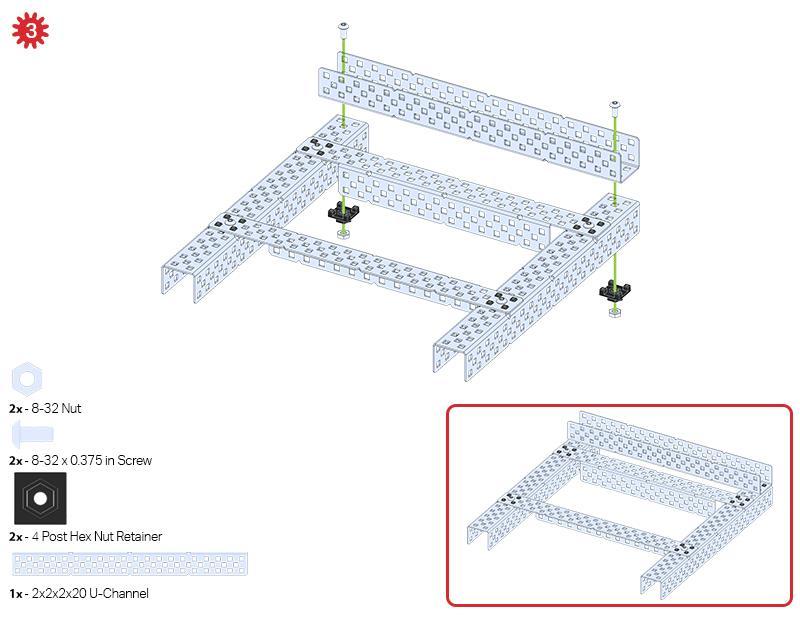
25 Build Instruction Tips Check the Appendix for info on how to use the new Hex Nut Retainers. Step 4: The green icon indicates that the build needs to be flipped over (upside down). Step 6: Only one of the two sub-assemblies made in this step is used right now. The other will be used later in step 9. Step 7: Make sure your Smart Motors are oriented in the correct direction (screw holes facing the outside of the build and the shaft hole towards the inside). Step 10: Make sure your Smart Motors are oriented in the correct direction (screw holes facing the outside of the build and the shaft hole towards the inside). Step 18: The green icon indicates that the build needs to be rotated (180 degrees). Step 20: The blue call out shows what the orientation of the Robot Brain should be if the build were flipped right side up. Make sure the 3 wire ports on the Robot Brain are facing the V5 Radio!
26 Step 22: The green call outs indicate which port on the Robot Brain to plug each device into using their respective cable.
27 Exploration The VEX EDR Speed Build is meant to get you comfortable working with the system as quickly as possible. Now that the build is finished, explore and see what it can do. Then answer these questions in your engineering notebook. What types of activities could this build be used for in real-world situations? What are the best features of this build? If you were tasked with designing a new version of this build, what would you add or remove from the build to improve its ability to push objects? Explain with details and sketches.
28 Play Test your build, observe how it functions, and fuel your logic and reasoning skills through imaginative, creative play.

29 Vision Sensor Description The Vision Sensor allows your robot to collect visual data from a live feed. The Vision Sensor is like a smart camera that can observe, select, adjust, and store colors and objects that appear in its visual field. Vision Sensor Common Uses: This sensor can be used for recognizing colors and color patterns. This sensor can be used to follow an object. This sensor can be used to collect information about the environment.

30 Technology as Inputs, Processing, and Outputs A piece of technology with inputs and outputs Technology as Inputs, Processing, and Outputs Technology exists to solve problems. A piece of technology, especially electronic and computerized technology, accomplishes this by taking input data, processing it into another useful form, and then outputting it to be used elsewhere. Different technologies involve different sets of inputs, outputs, and processes. For example, a calculator takes the sequences of numbers and mathematical operators a person inputs, processes those numbers and operations to calculate a result, and then outputs that result on a screen for the person. In robotics, sensors serve as the input by collecting data from the robot's environment. The robot brain runs a program that processes how the sensor input data should affect the robot behavior, and then the robot performs actions (output) such as spinning motors or displaying on the LCD.
 1 Engineering Notebook 3 Solid colored objects (green, yellow, and red) or the Color Tracking Printout (printed and cut out) 1 ColorTracking.")
31 Experimenting with the Vision Sensor Hardware/Software Required: Amount Hardware/Software 1 VEX EDR V5 Classroom Super Kit (with up-to-date firmware) 1 VEX Coding Studio (latest version, Windows, MacOS) 1 Engineering Notebook 3 Solid colored objects (green, yellow, and red) or the Color Tracking Printout (printed and cut out) 1 ColorTracking.vex Project File 1 Micro USB Cable Vision Sensor in Screw Attaching the Vision Sensor Attaching the Vision Sensor to the VEX EDR Speed Build


32 Use the instructions in the image above to attach the Vision Sensor to your VEX EDR Speed Build with a in Screw. 2. Connecting the Vision Sensor Connecting the Vision Sensor Using a V5 Smart Cable, connect the Vision Sensor to Smart Port 5 on the V5 Robot Brain. 3. Opening the Project File VEX Coding Studio prompt Download the ColorTracking.vex Project File from the Hardware/Software Required table at the top of this page. It contains the code needed for the vision sensor to complete the challenges in this STEM lab.


33 Then Launch VEX Coding Studio. Click on Open Project and select the ColorTracking.vex file to open it. 4. Observing the Program Blocks ColorTracking.vex Blocks view The program uses the Vision Sensor on the robot to look for 3 different color signatures: green, yellow, and red. If the Vision Sensor detects green, the robot drives forward. If it detects yellow, the robot turns to the right. If it detects red, the robot turns to the left. If none of those colors is detected, the robot stops.

34 5. Calibrating the Vision Sensor Vision Sensor connected using a Micro USB cable The ColorTracking.vex program includes color signatures for green, yellow, and red objects, but the exact coloring of your objects and lighting conditions of your area greatly impact the Vision Sensor readings. Configure color signatures for your green, yellow, and red objects in the lighting conditions where you are operating your robot. Be sure to store green as signature 1, yellow as signature 2, and red as signature 3 using the Vision Sensor Utility. After completing the color signature configuration, disconnect the Micro USB from the Vision Sensor.

35 6. Positioning the Robot VEX EDR Speed Build propped up Position the robot so that its wheels are not making contact with a surface, or so that it has room to move without running into obstacles or falling off of a surface. The program will automatically run once it has been downloaded to the robot.


36 7. Downloading and Running a Program The "Download to Robot" button in VEX Coding Studio Make sure that your robot is connected to your computer using the Micro USB Cable, and download and run the program. 8. Observing the Program Behavior VEX EDR Speed Build running the ColorTracking.vex program

37 Use the green, yellow, and red colored objects to control the movement of the robot. When you move one of the objects above the Vision Sensor, the LCD on the V5 Robot Brain should update to reflect that it detects the object and the Smart Motors should begin moving in the appropriate directions. In this configuration, which part of the system is acting as an input? Which part is performing the processing? What is the output? Record your findings in your engineering notebook. 9. Experimenting with Object Distance Varying the distance between the Vision Sensor and colored object

38 With each colored object, experiment with how far away the Vision Sensor is able to detect it. Is the detectable distance the same or different for each color? How important is it for each object to stay directly above the Vision Sensor? Record your findings in your engineering notebook. 10. Experimenting with Lighting Condition Varying the lighting conditions Move the robot and colored objects into another area with different lighting conditions (lighter or darker). Observe how the change in lighting conditions affects the Vision Sensor's ability to detect each colored object. Is any object affected more than the others? Record your findings in your engineering notebook.
39 Apply Become a 21st century problem solver by applying the core skills and concepts you learned to other problems.
40 Perception with Self-Driving Vehicles A self-driving vehicle with an array of sensors Perception with Self-Driving Vehicles Self-driving vehicles use a wide array of sensors to perceive their surroundings, on-board computers to combine and process the data from all of those sensors, and one or more motors to safely move the vehicle along the road. Self-driving vehicles often make use of high resolution cameras to be able to recognize things such as pedestrians, road signs, and other vehicles. Vision data from the cameras is often combined with sensors that use lasers to measure distance between the vehicle and other objects. This allows the on-board computers to make decisions based on what types of objects are in their environment, and how far away each object is.

41 VEX EDR V5 Ball Launcher VEX EDR V5 Ball Launcher Robot Capabilities The VEX EDR V5 Ball Launcher includes a Vision Sensor mounted above the robot, angled downward. This robot can be programmed to turn until the Vision Sensor detects a colored ball, and then drive toward it. When the Vision Sensor detects that the robot is close enough to the ball, the robot can pull it in using its intake, and then shoot it out at a target or goal.
42 Rethink Is there a more efficient way to come to the same conclusion? Take what you ve learned and try to improve it.
43 Prepare for the Vision Quest Challenge A sample of a Vision Quest course Challenge Preparation In this challenge, you need to drive your robot through a course of tight corridors using only the Vision Sensor and colored objects to guide its movement. Work with your classmates to design a course that requires the robot to complete at least 5 movements (forward, turn right, turn left) to get from the beginning to the end. To create the course you will need: Multiple boxes, books, 3-ring binders, or other objects to create walls Stopwatch (or use the program timer on the V5 Robot Brain) Colored paper or tape (to mark locations on the ground) to designate starting and ending zones Pencil and paper to record times
44 Improve Your Build Answer the following questions in your engineering notebook as you tinker with the build. Experiment with different placements and orientations of the Vision Sensor to improve your ability to control the robot using colored objects. Explain with details and/or sketches which changes you made. Experiment with controlling the robot using different colored objects. Record your results. Use the arrow button in the Vision Sensor Utility to expand or reduce the range of each color signature. How does this affect the Vision Sensor's ability to detect each object? Record your results. Make your changes to the build and then test them. Do you think your changes were generally successful? Why? Using what you've learned during testing, what changes do you have planned for your last iteration of the build before attempting the course? Explain with details and/or sketches what changes you would like to make.
45 The Vision Quest Challenge VEX EDR Speed Build in the Vision Quest course Vision Quest Challenge In this challenge, you need to drive your robot through a course of tight corridors using only the Vision Sensor and colored objects to guide its movement. Work with your classmates to complete the course using at least 5 movements (forward, turn right, turn left) to get from the beginning to the end. Compete with your classmates to see who can get through the course the fastest! Challenge rules: The robot must begin on the starting zone (indicated by paper or tape). The timer must start as soon as the robot moves. The timer should be stopped once the robot reaches the ending zone (indicated by paper or tape). Add five seconds to the end of your time every time the robot touches one of the course walls.
46 The robot must complete one run through the course. Stop the timer as soon as the robot reaches the designated end location. Have fun!
47 Know Understand the core concepts and how to apply them to different situations. This review process will fuel motivation to learn.
48 Review 1. Example of devices used to make inputs are: o Keyboard, mouse, scanner, printer o Keyboard, projector, controller, mouse o Scanner, mouse, controller, printer o Keyboard, scanner, controller, microphone 2. A self-driving vehicle uses sensors and motors to ensure riders are safe. o True o False 3. Example of devices to make outputs are: o Headphones, mouse, scanner, printer o Headphones, mouse, keyboard, printer o Keyboard, speakers, scanner, monitor o Headphones, screen, projector, printer 4. Taking data and changing it into another useful form in technology is: o Processing o Turning o Surrogate o Shifting 5. An open-loop system often requires something in its input-processingoutput that a closed-loop system does not require. What is it? o Robot o Controller o Monitor
49 o Human intervention

50 Appendix Additional information, resources, and materials.

51 Using the 1 Post Hex Nut Retainer w/ Bearing Flat 1 Post Hex Nut Retainer w/ Bearing Flat Using the 1 Post Hex Nut Retainer w/ Bearing Flat The 1 Post Hex Nut Retainer w/ Bearing Flat allows shafts to spin smoothly through holes in structural components. When mounted, it provides two points of contact on structural components for stability. One end of the retainer contains a post sized to securely fit in the square hole of a structural component. The center hole of the retainer is sized and slotted to securely fit a hex nut, allowing a 8-32 screw to easily be tightened without the need for a wrench or pliers. The hole on the end of the Retainer is intended for shafts or screws to pass through. To make use of the retainer: Align it on a VEX structural component such that the end hole is in the desired location, and the center and end sections are also backed by the structural component.
52 Insert the square post extruding from the retainer into the structural component to help keep it in place. Insert a hex nut into the center section of the retainer so that it is flush with the rest of the component. Align any additional structural components to the back of the main structural component, if applicable. Use an 8-32 screw of appropriate length to secure the structural component(s) to the retainer through the center hole and hex nut.

53 Perception with Self-Driving Vehicles A self-driving vehicle with an array of sensors Perception with Self-Driving Vehicles Self-driving vehicles use a wide array of sensors to perceive their surroundings, on-board computers to combine and process the data from all of those sensors, and one or more motors to safely move the vehicle along the road. Self-driving vehicles often make use of high resolution cameras to be able to recognize things such as pedestrians, road signs, and other vehicles. Vision data from the cameras is often combined with sensors that use lasers to measure distance between the vehicle and other objects. This allows the on-board computers to make decisions based on what types of objects are in their environment, and how far away each object is.

54 The Vision Quest Challenge VEX EDR Speed Build in the Vision Quest course Vision Quest Challenge In this challenge, you need to drive your robot through a course of tight corridors using only the Vision Sensor and colored objects to guide its movement. Work with your classmates to design a course that requires the robot to complete at least 5 movements (forward, turn right, turn left) to get from the beginning to the end. Compete with your classmates to see who can get through the course the fastest! Challenge rules: The robot must begin on the starting zone (indicated by paper or tape). The timer must start as soon as the robot moves. The timer should be stopped once the robot reaches the ending zone (indicated by paper or tape). Add five seconds to the end of your time every time the robot touches one of the course walls.
55 The robot must complete one run through the course. Stop the timer as soon as the robot reaches the designated end location. Have fun!

56 Using the 4 Post Hex Nut Retainer 4 Post Hex Nut Retainer Using the 4 Post Hex Nut Retainer The 4 Post Hex Nut Retainer provides five points of contact for creating a strong connection between two structural components using one screw and nut. Each corner of the retainer contains a post sized to securely fit in a square hole within a structural component. The center of the retainer is sized and slotted to securely fit a hex nut, allowing a 8-32 screw to easily be tightened without the need for a wrench or pliers. To make use of the retainer: Align it on a VEX structural component such that the center hole is in the desired location, and each corner is also backed by the structural component. Insert the square posts extruding from the retainer into the structural component to help keep it in place. Insert a hex nut into the center section of the retainer so that it is flush with the rest of the component.
57 Align any additional structural components to the back of the main structural component, if applicable. Use an 8-32 screw of appropriate length to secure the structural component(s) to the retainer through the center hole and hex nut.

58 Prepare for the Vision Quest Challenge A sample of a Vision Quest course Challenge Preparation In this challenge, you need to drive your robot through a course of tight corridors using only the Vision Sensor and colored objects to guide its movement. Work with your classmates to design a course that requires the robot to complete at least 5 movements (forward, turn right, turn left) to get from the beginning to the end. To create the course you will need: Multiple boxes, books, 3-ring binders, or other objects to create walls Stopwatch (or use the program timer on the V5 Robot Brain) Colored paper or tape (to mark locations on the ground) to designate starting and ending zones Pencil and paper to record times

59 Using the 1 Post Hex Nut Retainer 1 Post Hex Nut Retainer Using the 1 Post Hex Nut Retainer The 1 Post Hex Nut Retainer provides two points of contact for connecting a structural component to another piece using one screw and nut. One end of the retainer contains a post sized to securely fit in the square hole of a structural component. The other end of the retainer is sized and slotted to securely fit a hex nut, allowing a 8-32 screw to easily be tightened without the need for a wrench or pliers. To make use of the retainer: Align it on a VEX structural component such that both ends are backed by the structural component and positioned to secure the second piece. Insert the square post extruding from the retainer into the structural component to help keep it in place. If the retainer is being used to secure two structural components, insert a hex nut into the other end of the retainer so that it is flush with the rest of the component. If used to
60 secure a different type of component, such as a standoff, it may be appropriate to insert the screw through this side. Align any additional components to the back of the main structural component, if applicable. If the retainer is being used to connect two structural components, use an 8-32 screw of appropriate length to secure the structural components through the hole and hex nut. If used to connect a different type of component, such as a standoff, secure it directly or with a hex nut.

61 Engineering Notebooks Alexander Graham Bell's notebook entry from a successful experiment with his first telephone An Engineering Notebook Documents your Work Not only do you use an engineering notebook to organize and document your work, it is also a place to reflect on activities and projects. When working in a team, each team member will maintain their own journal to help with collaboration. Your engineering notebook should have the following: An entry for each day or session that you worked on the solution Entries that are chronological, with each entry dated Clear, neat, and concise writing and organization Labels so that a reader understands all of your notes and how they fit into your iterative design process An entry might include: Brainstorming ideas Sketches or pictures of prototypes
62 Pseudocode and flowcharts for planning Any worked calculations or algorithms used Answers to guiding questions Notes about observations and/or conducted tests Notes about and reflections on your different iterations

63 Parts Ne eded Can be built with: VEX EDR V5 Classroom Starter Kit
Medb ot. Medbot. Learn about robot behaviors as you transport medicine in a hospital with Medbot!
 Medb ot Medbot Learn about robot behaviors as you transport medicine in a hospital with Medbot! Seek Discover new hands-on builds and programming opportunities to further your understanding of a subject
Assembly Guide for Printrbot - Simple Maker s Edition 1405
 Assembly Guide for Printrbot - Simple Maker s Edition 1405 Last update: March 2016 Please Note: be careful on the steps that are underlined 1 Contents Tools Needed:... 3 First step: Check components and
Written By: Brook Drumm
 Simple 1401 Assembly For kits produced between 1/15/14-6/1/14. This guide is for kits with the Fan Shroud. Instructions for metal and wood extruder (and bed) included below. Written By: Brook Drumm TOOLS:
VEX IQ Troubleshooting Flowchart Controller & Controller Battery
 Controller & Controller Battery Controller Power/Link Charge/Game Does the Controller turn on When on, the Power/Link LED will be green or red. Unscrew the battery door of the Controller and ensure both
How to Build the Robotics++ V2 Robot. Last Edited Nov
 How to Build the Robotics++ V2 Robot Last Edited Nov. 15-2014 www.roboticscity.com 1 Completed Robotics++ V2 Robot. More views of completed robot can be found at the end of this instructions manual The
VEX Robotics Platform and ROBOTC Software. Introduction
 VEX Robotics Platform and ROBOTC Software Introduction VEX Robotics Platform: Testbed for Learning Programming VEX Structure Subsystem VEX Structure Subsystem forms the base of every robot Contains square
Quick Start Guide. Contents
 1 Quick Start Guide Contents Powering on the Machine Login/Password Entry Jaw Set Up High Security Cut by Code High Security Jaw Set Up Edge Cut Cut by Code Edge Cut Cut by Decode Cutter Replacement Tracer
Ev3 Robotics Programming 101
 Ev3 Robotics Programming 101 1. EV3 main components and use 2. Programming environment overview 3. Connecting your Robot wirelessly via bluetooth 4. Starting and understanding the EV3 programming environment
model tsa-sa48 Sliding Crosscut Table installation guide
 model tsa-sa48 Sliding Crosscut Table installation guide A Note About Color Variations Among Anodized Aluminum Components Congratulations on the purchase of this SawStop Sliding Crosscut Table. We at SawStop
Sliding Crosscut Table installation guide
 Sliding Crosscut Table installation guide model tsa-sa48 A Note About Color Variations Among Anodized Aluminum Components Congratulations on the purchase of this SawStop Sliding Crosscut Table. We at SawStop
HQ Precision-Glide Track Upgrade 2 Extension Kit for HQ Studio Frame Part# QF09750
 HQ Precision-Glide Track Upgrade 2 Extension Kit for HQ Studio Frame Part# QF09750 Important Note: Upgrading the track system on the HQ Studio Frame requires the use of this 2 Extension Kit (Part #QF09750),
MAKEBLOCK MUSIC ROBOT KIT V2.0
 MAKEBLOCK MUSIC ROBOT KIT V2.0 Catalog Music Robot Kit V2.0 Introduction... 1 1 What is Music Robot Kit V2.0?... 1 1.1 Mechanical part... 1 1.2 Electronic part... 1 1.3 Software part... 1 2 Music Robot
MILL ONE. Assembly Manual. Manual Illustrated by Gontarz Design Studio
 MILL ONE Assembly Manual Manual Illustrated by Gontarz Design Studio Safety Warnings and Guidelines 1. Be sure to carefully follow provided machine assembly instructions before machine use to ensure operator
DIY KITS FRAME KIT. Thank you for purchasing a 3DR Y6 DIY Kit!
 DIY KITS Y6 FRAME KIT Thank you for purchasing a 3DR Y6 DIY Kit! These instructions will guide you through assembling and wiring your new autonomous multicopter. CONTENTS Your 3DR Y6 Kit contains: 35 mm
TeacherGeek Sumo Bot Vehicle Application Guide
 SUMO BOT VEHICLE EXAMPLE BUILD TeacherGeek Sumo Bot Vehicle Application Guide TeacherGeek, 011 SUMO BOT VEHICLE EXAMPLE BUILD TeacherGeek TeacherGeek s Sumo Bot Vehicle Activity is the perfect way to encourage
Code Product Qty 1 Top Vertex 3 2 Hot End Housing 1 3 Bottom Vertex 3 4 Print Platform Lock 3 5 End Stop Holder 3 6 Filament Feeder Motor Bracket 1 7
 List of Parts Code Product Qty 1 680mm Extrusion 3 2 Power Supply 1 3 240mm Extrusion 9 4 42mm Nema 17 Stepper Motor 3 5 Slider-Hotend Connecting Rod 6 6 48mm Nema 17 Stepper Motor 1 7 Linear Rail with
TL4100 Top 5 Build Tips
 TL4100 Top 5 Build Tips 1: Top Plate When assembling the top plate, align the top of the top plate brackets with the top of the rods. This can be done by placing a hard flat object (such as a ruler) on
Printrbot Simple (Model 1403) Rev F Printrboard
 Rev F Printrboard") Printrbot Simple (Model 1403) Rev F Printrboard Printrbot Simple is currently shipping with the Rev F Printrboard. Check which rev Printrboard your Simple kit includes and use the corresponding instructions.
Printrbot Simple (Model 1403) Rev F Printrboard Printrbot Simple is currently shipping with the Rev F Printrboard. Check which rev Printrboard your Simple kit includes and use the corresponding instructions.
Robot Programming Manual
 2 T Program Robot Programming Manual Two sensor, line-following robot design using the LEGO NXT Mindstorm kit. The RoboRAVE International is an annual robotics competition held in Albuquerque, New Mexico,
INVENT3D Printer Kit Disassembly Instructions
 INVENT3D Printer Kit Disassembly Instructions Version 6 AST2 10/26/16 1 I. General Disassembly Instructions Use the case layer drawings to ensure that components are stored in the appropriate location
Parts of a Lego RCX Robot
 Parts of a Lego RCX Robot RCX / Brain A B C The red button turns the RCX on and off. The green button starts and stops programs. The grey button switches between 5 programs, indicated as 1-5 on right side
WARNING: Prior to installation, turn the power off to the vending machine and unplug it from its power source. Also, make sure to level the machine.
 Installation of Gum and Mint Tray for National 147, 157, 167 Important Note: Please read all instructions thoroughly before continuing with installation of kit. If you are having problems installing the
AM8 Printer A metal frame for your Anet A8 By Pheneeny v1.0 April 20, 2017
 AM8 Printer A metal frame for your Anet A8 By Pheneeny v1.0 April 20, 2017 Please read this entire document before printing parts or building this frame Disclaimer: This guide is for informational purposes
Ribcage Installation. Part 2 - Assembly. Back-Bone V1.06
 Ribcage Installation Part 2 - Assembly Back-Bone V1.06 Contents Section 1 Before You Get Started... 2 Included With Your Kit:... 2 Figure: A... 3 CAUTION!... 4 Note:... 4 Tools Required... 5 Section 2:
TeacherGeek Launcher Example Build
 LAUNCHER EXAMPLE BUILD TeacherGeek Launcher Example Build TeacherGeek, 2011 LAUNCHER EXAMPLE BUILD TeacherGeek 2 LAUNCHER BASE PARTS A B D F E C G LAUNCHER EXAMPLE BUILD TeacherGeek 3 ASSEMBLING THE LAUNCHER
ABM International, Inc. Navigator Assembly Manual
 ABM International, Inc. 1 1.0: Parts List Tablet (Qty. 1) Tablet mount (Qty. 1) NOTE: Mount may appear and operate different then image below Control Box (Qty. 1) Motor Power Supply (Qty. 1) 2 X-axis motor
Wanhao D9. Assembly and installation manual. This work is licensed under a Creative Commons Attribution 4.0 International License.
 Wanhao D9 Assembly and installation manual This work is licensed under a Creative Commons Attribution 4.0 International License. Table of Contents Introduction 2 Compatibility 2 What s in the box? 2 Raise3D
1.75mm Direct Titan Assembly
 1.75mm Direct Titan Assembly Learn how to assemble your Titan for use with 1.75mm filament in a direct configuration. Written By: Gabe S. 2018 e3d-online.dozuki.com/ Page 1 of 20 TOOLS: Hex Wrench, 1.5mm
5. Extruder Assembly
 5. Extruder Assembly Guide for the assembly of the Extruder. Written By: Josef Prusa 2017 manual.prusa3d.com Page 1 of 22 Step 1 Get the necessary tools 2.5 and 1.5 mm Allen key Needle-nose pliers Step
Installing Brackets to Minimize Distortion in Your SMART Board 685ix Interactive Whiteboard System s Projected Image
 UX60-RFK-685 Installing Brackets to Minimize Distortion in Your SMART Board 685ix Interactive Whiteboard System s Projected Image Follow these instructions to install brackets on your SMART Board 685ix
Maintenance Manual for Auto Lab
 Version 1.1 9/30/2012 Maintenance Manual for Auto Lab Lubricate X axis There are two locations for lubrication at the back side of the gantry as shown in the below picture. The left one (from the backside
(Assembling Guide supplied by imakr ) with the support of MyMiniFactory.com
 with the support of MyMiniFactory.com") (Assembling Guide supplied by imakr ) with the support of MyMiniFactory.com Summary Congratulations on beginning on your journey into 3D printing with the STARTT 3D printer. In this guide, you will have
(Assembling Guide supplied by imakr ) with the support of MyMiniFactory.com Summary Congratulations on beginning on your journey into 3D printing with the STARTT 3D printer. In this guide, you will have
The Portable Open Source 3D Printer
 http://web.archive.org/web/201502142011/http://www.tantillus.org/build_3.html Page 1 of 12 captures 12 Oct 12 - Feb 15 The Portable Open Source 3D Printer Home Start Case X/Y Axis Extruder Z Axis Electronics
Motorized or Crank Operated Fortress Zipper Track Shade with Housing and Side Track Installation Instructions
 Motorized or Crank Operated Fortress Zipper Track Shade with Housing and Side Track Installation Instructions Tools Needed Drill 3/8 Metal Drill Bit ¼ Masonry Drill Bit Measuring Tape Pencil 4 Level Phillips
Kossel Rev B Build Guide V1.0
 Kossel Rev B Build Guide V1.0 1 Table of Contents: Step 1: BASE ASSEMBLY Gathering parts: Building the Corners and Base: Step 2: UPPER ASSEMBLY Building Upper: Step 3: VERTICAL RAIL INSTALLATION Building
MODEL T28173/T28174 ROLLER TABLES INSTRUCTIONS
 MODEL T28173/T28174 ROLLER TABLES INSTRUCTIONS FOR MODELS MFD. SINCE 10/17 For questions or help with this product contact Tech Support at (570) 546-9663 or techsupport@grizzly.com Rails Rollers Reversible
Orbital Test Stand. Operations and Assembly Manual. Department of Mechanical Engineering Northern Arizona University Flagstaff, AZ 86011
 Orbital Test Stand Operations and Assembly Manual Department of Mechanical Engineering Northern Arizona University Flagstaff, AZ 86011 TABLE OF CONTENTS 1.0 Components List... 2 2.0 Assembly Instructions...
SuperTrack Parts List
 SuperTrack Parts List [indicates number for 6 lane tracks] SuperTrack Installation Instructions www.supertimer.com 1-800-654-2088 1 Track Instruction Manual (this booklet) 2 Start sections [3] Start Gate
Nebraska 4-H Robotics and GPS/GIS and SPIRIT Robotics Projects
 Name: Club or School: Robots Knowledge Survey (Pre) Multiple Choice: For each of the following questions, circle the letter of the answer that best answers the question. 1. A robot must be in order to
LANDING GEAR. 1. Fit landing gear into slots on bottom of fuselage.
 LANDING GEAR 1. Fit landing gear into slots on bottom of fuselage. 4. Use channel-lock pliers to press blind nuts into position (note: drilled hole should be slightly smaller than shaft of blind nut for
Hatch Whiteboard: Portable Stand Installation Instructions
 Hatch Whiteboard: Portable Stand Installation Instructions Remove Projector Wall Plate 1. Open the wall mount for the projector. 2. Remove the shipping screw from the front center of the mount arm. 1 P
Removing and Replacing the Y-truck
 Service Documentation Removing and Replacing the Y-truck To remove and replace the Y-truck you will need the following tools: 4mm Allen wrench 12mm stamped flat wrench #2 Phillips screwdriver (magnetic
1. ASSEMBLING THE PCB 2. FLASH THE ZIP LEDs 3. BUILDING THE WHEELS
 V1.0 :MOVE The Kitronik :MOVE mini for the BBC micro:bit provides an introduction to robotics. The :MOVE mini is a 2 wheeled robot, suitable for both remote control and autonomous operation. A range of
I.1 Smart Machines. Unit Overview:
 I Smart Machines I.1 Smart Machines Unit Overview: This unit introduces students to Sensors and Programming with VEX IQ. VEX IQ Sensors allow for autonomous and hybrid control of VEX IQ robots and other
Lead Screw Upgrade. How to upgrade your ROBO R1 to the new Lead Screw Upgrade Pack. Written By: Harrison Team RoBo 3D
 Lead Screw Upgrade How to upgrade your ROBO R1 to the new Lead Screw Upgrade Pack. Written By: Harrison Team RoBo 3D 2017 guide.robo3d.com Page 1 of 14 Step 1 Lead Screw Upgrade Begin by powering off and
Gear Drive Hapkit Assembly Instructions
 Gear Drive Hapkit Assembly Instructions (1) Order and Print the necessary parts Figure 1: 3D Printed Parts and Hardware Note: The screws shown were replaced with button head screws and the second pair
Astro-Physics Inc. 400QMD Lubrication/Maintenance Guide
 Astro-Physics Inc. 400QMD Lubrication/Maintenance Guide The following guidelines should be followed to lubricate the three main parts of the 400QMD mount. The QMD stands for Quartz Micro-Drive controller.
V4 Premium Kit. Prusa i3 Build Guide
 V4 Premium Kit Prusa i3 Build Guide Hi! Congratulations on your purchase of the DIYElectronics.co.za Prusa I3 kit, the best South African 3D Printer Kit! Hopefully this should serve as complete guide to
meped v2 Assembly Manual
 meped v Assembly Manual The meped is an open source quadruped robot designed by Scott Pierce of Spierce Technologies, LLC. This design is released under the Creative Commons, By Attribution, Share Alike
Giraud Tool Company, Inc.
 Motor Upgrade for Gracey Trimmer This package is intended to allow the user to upgrade their Gracey trimmer with a higher rpm motor and convenience features not found in the production offering. This upgrade
Unit 4: Robot Chassis Construction
 Unit 4: Robot Chassis Construction Unit 4: Teacher s Guide Lesson Overview: Paul s robotic assistant needs to operate in a real environment. The size, scale, and capabilities of the TETRIX materials are
M2 Assembly. M2 Sub-Assemblies mm Belt Sub-Assembly mm Belt Sub-Assembly Spider Sub-Assembly... 4
 M2 Assembly Table of Contents M2 Sub-Assemblies... 3 630mm Belt Sub-Assembly... 3 702mm Belt Sub-Assembly... 3 Spider Sub-Assembly... 4 Idler Bolt Sub-Assembly... 8 Y Motor Sub-Assembly... 9 X Motor Sub-Assembly...
Customers should turn off the machine with the power cable and USB data cable pulled down from it when installing or removing extruder.
 INSTALLATION &REMOVAL of the EXTURDER Customers should turn off the machine with the power cable and USB data cable pulled down from it when installing or removing extruder. I.How to disassemble the extruder
The light sensor, rotation sensor, and motors may all be monitored using the view function on the RCX.
 Review the following material on sensors. Discuss how you might use each of these sensors. When you have completed reading through this material, build a robot of your choosing that has 2 motors (connected
EmagiKit. Privacy Pod Plus. Quiet. Easy. Affordable. INSTRUCTIONS ASSEMBLY
 EmagiKit Privacy Pod Plus Quiet. Easy. Affordable. INSTRUCTIONS ASSEMBLY DIMENSIONS AND COMPONENTS 47 47 Ceiling Unit 2-B 2-L 2-R Glass Door Corner Trim Door Handle 90 Adjustable Height Work Surface 1-B
Classic SportBar Camaro V6 or V8
 Classic SportBar 2011-2015 Camaro V6 or V8 The Classic SportBar is intended for restyling purposes only and does NOT provide roll over protection. Read entire installation guide before starting. Component
OpenROV. Guide 3 - Electronics. We will now move to the assembly of the electronics that will control the ROV. Written By: OpenROV
 OpenROV Guide 3 - Electronics We will now move to the assembly of the electronics that will control the ROV. Written By: OpenROV 2017 openrov.dozuki.com Page 1 of 33 INTRODUCTION We will introduce soldering
Introduction to the VEX Robotics Platform and ROBOTC Software
 Introduction to the VEX Robotics Platform and ROBOTC Software Computer Integrated Manufacturing 2013 Project Lead The Way, Inc. VEX Robotics Platform: Testbed for Learning Programming VEX Structure Subsystem
Delta Rostock mini G2& G2s Building instruction
 Delta Rostock mini G2& G2s Building instruction Safety Instructions ShenZhen GETECH CO.,LTD Building the printer will require a certain amount of physical dexterity, common sense and a thorough understanding
Rocketry Challenge - Technical Document I
 Rocketry Challenge - Technical Document I This document includes a list of what is inside the kit with pictures for hard to decipher parts and a simple step-by-step process of how to assemble and launch
High Rise Sit-Stand Desk Converter
 High Rise Sit-Stand Desk Converter Assembly Instructions for Model DC350 Patent No. 9,332,839 PRE-ASSEMBLY Please read all instructions before beginning assembly. We strongly recommend you watch the video
Z-Truck Up-and-Down Motion. Y-Truck Side-to-Side Motion. Head. Squaring Plate. Sliding Plate FIGURE 1: THE CARVEWRIGHT MACHINE
 Setup and use of CarveWright CO2 Powered Dragster Jig The CO 2 powered Dragster Jig will arrive from the factory fully assembled, calibrated, and squared. In order to get the best results, your CarveWright
Your EdVenture into Robotics 10 Lesson plans
 Your EdVenture into Robotics 10 Lesson plans Activity sheets and Worksheets Find Edison Robot @ Search: Edison Robot Call 800.962.4463 or email custserv@ Lesson 1 Worksheet 1.1 Meet Edison Edison is a
BIGBOT ASSEMBLY INSTRUCTIONS. 1/18/2017 V0.5
 BIGBOT ASSEMBLY INSTRUCTIONS www.bigbot-3d.com 1/18/2017 V0.5 FOREWORD: PLEASE TAKE CARE WHEN HANDLING THE GANTRY. THE ASSEMBLY SHOULD BE HANDLED ONLY BY THE ALUMINUM FRAME, AND AVOID TOUCHING OR LIFTING
Assemble Instruction of Geeetech Acrylic. Prusa I3 Pro C
 Assemble Instruction of Geeetech Acrylic Prusa I3 Pro C Version 04-11-2016 Safety Instructions Building the printer will require a certain amount of physical dexterity, common sense and a thorough understanding
3D PRINTER. Pack 11. Anything you can imagine, you can make! 3D technology is now available for you at home! BUILD YOUR OWN
 BUILD YOUR OWN Pack 11 Anything you can imagine, you can make! 3D PRINTER Compatible with Windows 7 & 8 Mac OS X 3D technology is now available for you at home! BUILD YOUR OWN 3D PRINTER CONTENTS PACK
Assemble Instruction of Geeetech Acrylic Prusa I3. Pro & pro B
 Assemble Instruction of Geeetech Acrylic Prusa I3 Pro & pro B Version 04-11-2016 Safety Instructions Shenzhen GETECH CO.,LTD Building the printer will require a certain amount of physical dexterity, common
Tin Lizzie 18 Assembly Instructions
 Tin Lizzie 18 Assembly Instructions Revision: 07/29/16 Table of Contents Aides 3 Before You Begin 5 Aides 5 Tools 6 Perfect Stitch Parts 2 12 Modify the Machine 12 Prepare Drill Templates 12 Front Display
400GTO Lubrication Guide
 400GTO Lubrication Guide Lubrication Guidelines for the following equatorial mounting: 400GTO Servo with GTOCP2 or CP3 Controller For other 400 models please review other postings as they become available.
This guide contains everything you need to set up and operate all three. Inspira Imperial Quilting Frame Assembly...2
 Congratulations on the purchase of your Husqvarna Viking Mega Quilter 18x8, Inspira Imperial Quilting Frame, and QBOT by Inspira! This guide contains everything you need to set up and operate all three.
The Mind Project s Iris 1 Robotic Arm. Assembly instructions Step 1
 The Mind Project s Iris 1 Robotic Arm Assembly instructions Step 1 Packing list Below you will find pictures and descriptions of each part. It may be helpful to take each piece out of the bag and place
PoeBot Building Instructions CCISD. Upper Gripper. Lower Gripper/ Spatula. PoeBot Instructions PLTW. Clear Creek ISD
 Upper Gripper Lower Gripper/ Spatula PoeBot Instructions PLTW Clear Creek ISD 1. Chasis Construction (Split Group with half starting Step 1 and half starting Step 13.) Note: These flat bearings are offset
Congratulations on your decision to purchase the Triquetra Auto Zero Touch Plate for All Three Axis.
 Congratulations on your decision to purchase the Triquetra Auto Zero Touch Plate for All Three Axis. This user guide along with the videos included on the CD should have you on your way to perfect zero
4. Z-axis assembly. 4. Z-axis assembly. Written By: Josef Prusa manual.prusa3d.com Page 1 of 18
 4. Z-axis assembly Written By: Josef Prusa 2017 manual.prusa3d.com Page 1 of 18 Step 1 Get the necessary tools 13/17mm spanners 3.6mm flathead screwdriver Needle-nose pliers 2.5 and 1.5mm Allen key Step
Problem/Procedure Description. Requirements. Problem/Procedure Solution. How-To Document. Updated on: 11/13/2008 By:Christopher Ware
 Problem/Procedure Description Performing maintenance on 95s, 95sII and H100 Requirements Ball Bearing Grease (LPKF P/N 106976) Tri-Flow Teflon lubricant aerosol. 3-in-1 Multi-purpose Oil Electronic Component
Range height adjustable assembly
 Table of contents Digital handset operation 3 Height adjustable bench kit 4-5 Cable carrier 6 Ganging tray and ganging rail 7 Height adjustable return frame kit 8 Cable entry pole 9 24 and 30 d worksurfaces
Robotics using Lego Mindstorms EV3 (Intermediate)
") Robotics using Lego Mindstorms EV3 (Intermediate) Facebook.com/roboticsgateway @roboticsgateway Robotics using EV3 Are we ready to go Roboticists? Does each group have at least one laptop? Do you have
Robotics using Lego Mindstorms EV3 (Intermediate) Facebook.com/roboticsgateway @roboticsgateway Robotics using EV3 Are we ready to go Roboticists? Does each group have at least one laptop? Do you have
The Derby Magic Company Track Assembly Instructions, revision F page 1 of 13
 The Derby Magic Company Track Assembly Instructions, revision F page 1 of 13 Thank you for purchasing a Derby Magic Pinewood Derby Track. To assemble your track, start with the stand. The parts of the
Mill One V2 Assembly Manual
 Mill One V2 Assembly Manual Throughout this policy the words "we", "us" and "our", or Sienci Labs will be used to refer to Sienci Labs Inc. herein and Mill One or machine will refer to Sienci Labs Sienci
PRS Retro Z-Axis Installation
 PRS Retro Z-Axis Installation Page -1- PRS Retro Z-Axis Installation This document is a guide to installing the PRS Retro Z-axis on early ShopBot models. It describes installation for PR models with PK299
CRP700 Benchtop Basic CNC Machine Assembly Instructions. Updated 9/11/2014 SHEET 1 of 25
 CRP700 Benchtop Basic CNC Machine Assembly Instructions Updated 9//0 SHEET of NOTE: This piece of extrusion is mounted wide side up Quick Tip: Lay extrusion on table as shown for easy assembly BASE ASSEMBLY:.
Assemble Instruction of Geeetech Acrylic Prusa I3. pro C
 Assemble Instruction of Geeetech Acrylic Prusa I3 pro C Safety Instructions Shenzhen GETECH CO.,LTD Building the printer will require a certain amount of physical dexterity, common sense and a thorough
Kit 102 Series Installation Instructions for Wood or Metal Posts on Level Runs
 Kit 102 Series Installation Instructions for Wood or Metal Posts on Level Runs A. Drill Posts Hole size for 1/8" or 3/16" cable installation This kit may also be used for stairs or runs that exit the end
BUILD YOUR OWN. Pack 22
 BUILD YOUR OWN TM Pack 22 01 CONTENTS Assembly Guide 339 Stage 70: The front brake lever Stage 71: The oil hose and the twistgrip Stage 72: Fitting the front fork assembly Editorial and design by Continuo
Making Instructions Version 2.1 for Raspberry Pi
 Making Instructions Version 2.1 for Raspberry Pi Ohbot Ltd. 2017 About Ohbot has seven motors. Each connects to the Ohbrain circuit board and this connects to a computer using a cable. Ohbot software allows
PH03 Comfort XL Front Assembly Replacement Instructions
 PH03 Comfort XL Front Assembly Replacement Instructions POLYJOHN USA PolyJohn Enterprises Corp 2500 Gaspar Ave. Whiting, IN 46394 Phone: 800-292-1305 Fax: 219-659-0625 www.polyjohn.com info@polyjohn.com
CRP700 Benchtop Basic CNC Machine Assembly Instructions. Updated 10/24/2014 SHEET 1 of 24
 CRP700 Benchtop Basic CNC Machine Assembly Instructions Updated 0//0 SHEET of NOTE: This piece of extrusion is mounted wide side up Quick Tip: Lay extrusion on table as shown for easy assembly BASE ASSEMBLY:.
Downloading a ROBOTC Sample Program
 Downloading a ROBOTC Sample Program This document is a guide for downloading and running programs on the VEX Cortex using ROBOTC for Cortex 2.3 BETA. It is broken into four sections: Prerequisites, Downloading
Bipedinno. 12-DOF Waist-high Robot
 Bipedinno 12-DOF Waist-high Robot Instruction Manual Version 1.18 Trademark Innovati,, and BASIC Commander, are registered trademarks of Innovati Inc. InnoBASIC and cmdbus are trademarks of Innovati Inc.
IGNITE BASICS V1.1 19th March 2013
 IGNITE BASICS V1.1 19th March 2013 Ignite Basics Ignite Basics Guide Ignite Basics Guide... 1 Using Ignite for the First Time... 2 Download and Install Ignite... 2 Connect Your M- Audio Keyboard... 2 Open
Agent-based/Robotics Programming Lab II
 cis3.5, spring 2009, lab IV.3 / prof sklar. Agent-based/Robotics Programming Lab II For this lab, you will need a LEGO robot kit, a USB communications tower and a LEGO light sensor. 1 start up RoboLab
OTECO INC. MODEL ,000 PSI 4-1/16 PORT DM GATE VALVE MAINTENANCE MANUAL
 Page 1 of 7 OTECO INC. MODEL 45 4 5,000 PSI 4-1/16 PORT DM GATE VALVE MAINTENANCE MANUAL Page 2 of 7 TABLE OF CONTENTS 1. Assembly Blowout 2. Repair Kit Contents & Technical Specifications 3. Disassembly
Budget Robotics Octabot Assembly Instructions
 Budget Robotics Octabot Assembly Instructions The Budget Robotics Octabot kit is a low-cost 7" diameter servo-driven robot base, ready for expansion. Assembly is simple, and takes less than 15 minutes.
7878 K940. Checkpoint Antenna. Kit Instructions. Issue B
 7878 K940 Checkpoint Antenna Kit Instructions Issue B Revision Record Issue Date Remarks A July 7, 2009 First issue B Nov2013 Revised the Checkpoint installation procedures for 7878 and 7874 scanners Added
RPS. XR Front Drive Updates CORPORATION
 FACTORY CAT 1. To start a replacement of the XR Front Wheel Drive, make sure the machine is on level ground with the rear wheels chocked and always disconnect the batteries. 2. Locate the Positive and
The Derby Magic Company Track Assembly Instructions, revision E page 1 of 12
 The Derby Magic Company Track Assembly Instructions, revision E page 1 of 12 Thank you for purchasing a Derby Magic Pinewood Derby Track. To assemble your track, start with the stand. The parts of the
Volkswagen Window Regulator Repair
 The tools you will need to complete the repair will be a T20 Torx screwdriver and a Flat Screwdriver additionally, you could also use a pair of pliers to remove the plastic plug holding the wire nearest
Bone Box. Created by Phillip Burgess. Last updated on :31:04 PM UTC
 Bone Box Created by Phillip Burgess Last updated on 2018-08-22 03:31:04 PM UTC Guide Contents Guide Contents Preparation Parts List Before assembly Assembly 1: Attach BeagleBone to Base Plate 2: Assemble
Maintenance Information
 47104302 Edition 1 November 2012 Cordless Drill/Driver QX Series Maintenance Information Save These Instructions Tool Diagnosis 1. Before servicing this unit, you will need a fully charged battery of known
The Useless Machine. Parts Only - Build Guide v0001
 TM The Useless Machine Parts Only - Build Guide v0001 For the best outcome, follow each step in order. We recommend reading this guide entirely before you get started. Tools required: One phillips screwdriver,