Bipedinno. 12-DOF Waist-high Robot
|
|
|
- Julian Henderson
- 5 years ago
- Views:
Transcription

1 Bipedinno 12-DOF Waist-high Robot Instruction Manual Version 1.18
2 Trademark Innovati,, and BASIC Commander, are registered trademarks of Innovati Inc. InnoBASIC and cmdbus are trademarks of Innovati Inc. Copyright by Innovati Inc. All rights reserved. In view of unceasing improvement of products, this document and the product mentioned in this document are subject to be changed by the company without notice. It is forbidden to reproduce and distribute any part or all of the contents of the product without the written approval or authorization by the company. Disclaimer The user shall undertake all the risks in the applications where this product is used. The company shall not be liable for any direct, indirect or consequential damages due to the use of the product including but not limited to the loss of equipment, the loss of human safety and health and the loss of profit and reputation. The product of the company shall not be used in life saving or any related instrument and equipment. Children under 14 shall not use this product for any related experiment without being accompanied by adults. Errata We hope the users may regard this document as a lively and practical instruction manual. We have put tremendous efforts in making this instruction manual complete and correct; however, there may be unavoidable missing parts or errors. With a view to providing the user updated and complete information in the instruction manual, we keep improving and supplement the contents of this instruction manual. If you find any error in this manual, please contact us via the service@innovati.com.tw. Any related update information will be disclosed on our website. Please visit our website for more updated information. i
3 Precautions This kit comprises 2 modules, BASIC Commander and Servo Runner A, each with respective instructions for use and functions. Please refer to these for optimal effects. When installing BASIC Commander to the Command Board, make sure the input voltage is within the 6-12V range, otherwise the module may burn. The input voltage to the Servo Runner A must correspond to the voltage rating of the servo. Servos provided in this kit are rated 4.8-6V; over or under voltage may cause unpredictable results, even burning of the motor. Make absolutely sure of the correct voltage before connecting the power supply. The kit provides a total of 12 servos. When operated simultaneously, they consume a large current; make sure the power supply or battery connecting to Servo Runner A is capable of providing 8A of current, so as to properly operate the kit. Insufficient current may cause unexpected results and damage of the kit. When using a battery power supply to the module, the voltage may lower after some while of operation and cause abnormal actions of the kit. In such case, remove and fully charge the battery before using again. If prolonged testing and operation is required, we suggest you use a power supply unit to ensure uniform performance. Prior to assembling the kit, install InnoBASIC Workshop as per the content of the CD; also make sure that the PC communicates with BASIC Commander via a USB cable connection, so that the entire assembly can be accomplished. ii
4 Table of Contents Part List...1 Tools...4 Assembly Procedure...5 Calibration Servos...5 Assemble the Leg Frames...10 Connecting Top Board with Module...16 Fine-Tuning Initial value of Servo...21 Structure fine-tuning...21 Software fine-tuning...21 Perform Demonstrative Motions...27 iii


5 Part List Item Illustration Qt y Specifications and instructions Assembly Kit Parts Main Board for installing module 1 PC installation board for linking robot electronic modules with its leg parts; provides versatile layout of module or power supply accessories. Top Board for installing module 1 PC board for installing electronic module of the robot and connecting with the main board; provides versatile layout of modules. Aluminum Foot Bracket 2 For connecting with the Ankel Servo Bracket. Aluminum Servo Bracket 12 For accommodating and fixing servo; lock holes are provided for connecting with another Servo Bracket or U-shape Bracket. Aluminum U-shape Bracket, 27mm 4 Provides connection with the Servo Bracket and movement space of the Servo; it also provides connection with two U-shape Brackets for different applications. Aluminum U-shape Bracket, 22mm 8 Provides connection with the Servo Bracket and movement space of the Servo; it also provides connection with two U-shape Brackets for different applications. 1
: 40.6mmx20.0mmx42.8mm Weight: 73 g, Speed: 0.33 sec/60 Torque: 7.")
6 Servo 12 Servo provides for 180 rotation moves capable of simulating articulation behaviors; connections with signal, power and ground are required for the operation. Pay attention to wire polarity. Avoid having the servo sustained to a same movement for a long period of time, to prevent wearing the motor. Dimensions (LxWxH): 40.6mmx20.0mmx42.8mm Weight: 73 g, Speed: 0.33 sec/60 Torque: 7.4 kg/cm Screw A 48 ISOT 3 x 8 mm Screw B 10 ISOP 3 x 6 mm Screw C 20 ISOP 3 x 10 mm Screw D 32 ISOP 2 x 5 mm Screw E 40 TP1P 2 x 6 mm Screw F 8 TP1P 2 x 8 mm Screw G 4 ISOF 3 x 6 mm Screw H 8 ISOF 2 x 5 mm Nut A 90 3 x 5 mm Nut B 32 2 x 4 mm Washer A 72 3 x 0.4 x 8 mm Washer B 12 3 x 1 x 6 mm Bearing 12 3 x 4 x 8 x 9.5 mm 2


7 Hex post, copper 4 30 mm Module Kits BC1 1 Innovati BASIC Commander, capable of storing programs and controlling operations of modules Servo Runner A 1 Innovati Servo Runner A, for controlling individual servos. Command Board 1 Used for installing BC1, with spare cmdbus allowing user to connect with Innovati modules. Servo Power Line 1 Cable for connecting Servo Runner A with Power Supply Unit. Command Power Line Board 1 Cable for connecting Command Board with Servo Runner A s Power Supply. cmdbus 1 Signal cable for connecting Command Board with Servo Runner A. Servo Extension Cable 4 Extends controlling signal cable of the Servo, so that the user may perform Servo control with a larger range or longer distance. 3

.")
8 USB cable 1 Links BC1 with PC, allowing downloading of PC program to BC1, or performing communication in Debug Mode. Cable Strap 12 Used for fixing wires, so that they do not tangle or affect motions unexpectedly during the operation of the Servo. i. Tools Cross Screwdriver (2mm and 3 mm). Long Nose Pliers Screw Glue (selectively used between nut and Bracket joints, to prevent the nut from loosening.) 4

9 ii. Assembly Procedures Calibrating Servos Before starting installation, verify if the servo horn is at the correct position; if not, calibrate as follows: Connect servo, Servo Runner A, Command Board, and power supply cable in the sequence as illustrated below. Connect to power with Servo Power Line. Mind the polarity. Connect + to the positive and - to the negative of the power supply. Connect to Command Board with Education Board Power Line. Make sure to connect + to the positive and - to the negative of the power supply. Connect all servos with Servo Runner, as shown in the Fig. Pay attention to the pin position while making the connection. Connect to Command Board with cmbbus, and install BC1 to Command Board. Make sure the Power Switch on the Command Board is set to 0 (off). When the Command Board or Education Board shares the power supply with Servo Runner A, please notice that the voltage of this kit should be 6V (please refer to Notices). It is recommended to use a voltage regulator to ensure that the voltage is within the safe range. i. Connect the PC and BASIC Commander with a USB cable. ii. Make sure that the DIP switch on the Command Board is set at the 0 position (power off state). If it is not at the 0 position, please poke it to the 0 position. iii. Connect the power line of the servo to the power supply. (Please make sure that the voltage and current from the power supply are within the ranges required by the servo. After the power line is connected, the servo may make a transient motion due to receiving a switch surge; this is normal. While connecting the power line, please pay attention not to place your hands within the space where the servo may move to avoid being clamped.) 5
10 iv. Start the InnoBASIC Workshop Click the application in the InnoBASIC Workshop folder to start the InnoBASIC Workshop. v. Click the Tools item in the menu bar on the top. After clicking each item, a pull-down menu with more function items will be displayed. Please click the Tools" item now. vi. Click the Motion Editor in the pull-down menu (If a warning window appears, it means that the BASIC Commander is not correctly connected. Please check if the USB cable is connected or unplug and then plug it again to ensure a correct connection. Exit the Motion Editor and then re-click this button.) Click Motion Editor to start the Motion Editor. If this message appears, it means that the USB cable is not connected correctly. vii. viii. If the connection is correct, the message Downloading servo manager... will be displayed on the PC screen meaning that the program is being downloaded. Please poke the DIP switch on the Command Board to the 1 position and wait a moment. The message means that the program is being downloaded. Please do not remove the USB cable. After the downloading is complete, a notification window will appear. Please make sure that each servo has been connected correctly. After confirming all the connections, please click OK. (If Cancel is clicked, the Motion Editor will be closed. If there is any component is incorrectly connected at this moment, please click Cancel to terminate the program.) 6

11 The message appears for notifying the download is complete. Please make sure that each component has been connected correctly. ix. Please pay attention not to place your hands within the space where the servos may move into to avoid being clamped. Please check the checkbox for activating the servos on the left side to move all the servos to their central points. Please note that the number next to it should be If it is not 1500, please click the number directly, enter the number 1500 and then click Enter. Check if the disks of all servos are at correct position; in case of any deviation, remove the central screw and pull off the disk, adjust it to the correct angle and re-lock. If the hole is in an incorrect position, loosen this screw and pull up the disk; adjust the disk to the correct position and refit the disk and replace the screw. There are 4 sets of 3 holes on the disk of the servo. Verify if the central hole is on the top of the disk in a right angle, as shown in the figure. While making the assembly, before fixing the disk, make sure the disk is maintained at the correct angle. In case the disk is moved, follow this procedure to adjust it, to prevent from any unexpected movement or damage of the parts. 7
12 Installing the bearing (For reference only. Please do not assemble it first.) Servo Plate U-shape Bracket While connecting the Servo Bracket and the U-shape Bracket, the bearing should be used for the joints with the same fixing methods. Pass the Screw C from outside towards the inside through the bearing mounted on the U-shape Bracket, then the Washer B and the Servo Bracket. Finally, fix it with the Nut A at the inner side of the Servo Bracket. Bearing fixed on U-shape Bracket Nut A Washer B Screw C Fixing the servo (For reference only. Please do not assemble it first.) Servo is fixed on the Servo Plate with Screw A passing through Washer A and the square hole on the motor, tightened with Nut A from the lower side of Servo Plate. Screw A Washer A Screw A After fixing servo, fix U-shape Bracket to secervo horn with Screw E. Make sure the disk is not disturbed. 8


13 A. Assemble the leg frames i. Assemble the Right Leg Frame Part A: Align two Servo Brackets and fix them with Screw D and Nut B. Part B: Place 27mm U-shape Bracket together with Servo Bracket as shown, fix them with Screw D and Nut B. Part C: Place 22mm U-shape Bracket together with Servo Bracket as shown, fix them with Screw D and Nut B. Part D: Place two 22mm U-shape Brackets back to back as shown, fix them with Screw B and Nut A. Add bearings to each U-shape Bracket on the same side. Part E: Align two Servo Brackets as shown; fix them with Screw D and Nut B. Part F: Fix the Foot Bracket to the 27mm U-shape Bracket with Screw G and Nut A. Make sure the screw points upwards. 9


14 Connect Part A on top of Part B and fix them with a bearing. The upper-most part is Servo Bracket of Part A. Note the positions of fixing holes on both Part A and Part B. Connect Part B above with Part C and fix them with a bearing; now that two U-shape Brackets are perpendicular to each other, with the 27mm U-shape Bracket on the top. Using Part D as the center, connect its lower side to Part E with a bearing, then its upper side to Part C with another bearing, so that a Servo Bracket is at the bottom and a 22mm U-shape Bracket at the top, as shown. Finally fix the lowest Servo Plate to Part F with a bearing and the Right Leg Frame is complete. Check if the Right Leg Frame conforms to the structure in the illustration. 10


15 ii. Assemble Left Leg Frame Part A: Align two Server Plates as shown; fix them with Screw D and Nut B. Part B: Place the 27mm U-shape Bracket together with Servo Plate as shown; fix them with Screw D and Nut B. Part C: Place the 22mm U-shape Bracket together with Servo Plate as shown; fix them with Screw D and Nut B. Part D: Place two 22mm U-shape Brackets back to back as shown and fix them with Screw B and Nut A. Place bearings on the U-shape Brackets on the same side. Part E: Align two Servo Plates as shown; fix them with Screw D and Nut B. Part F: Fix the Foot Bracket with 27mm U-shape Bracket with Screw G and Nut A. Make sure the screw points upwards. 11


16 Connect Part A on top of Part B and fix them with a bearing. The upper-most part is Servo Plate of Part A. Note the positions of fixing holes on both Part A and Part B. Connect Part B above Part C and fix them with a bearing; now that two U-shape Brackets are perpendicular to each other, with the 27mm U-shape Bracket on the top. Using Part D as the center, connect its lower side to Part E with a bearing, then its upper side to Part C with another bearing, so that a Servo Plate is at the bottom and a 22mm U-pate at the top as shown. Finally fix the lowest Servo Plate to Part F with a bearing and the Left Leg Frame is complete. Check if the Left Leg Frame conforms to the structure in the illustration. 12

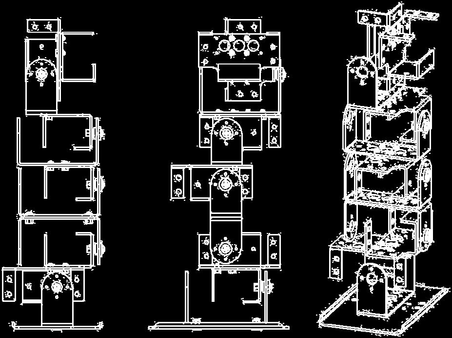

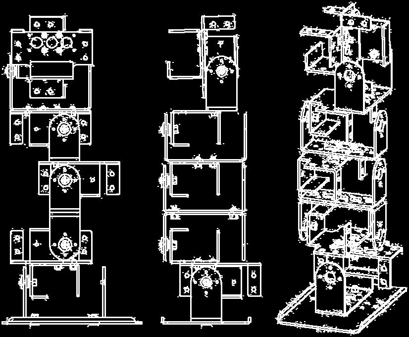
17 Confirmation of the Right Leg Frame Confirmation of the Left Leg Frame 13


18 iii. Connecting the Left and Right Legs Place two 22mm U-shape Brackets back to back as shown. Then, fix them with Screw B and Nut A and add bearings to each U-shape Bracket on the same side. Connect the bearing to the Servo Bracket on top of leg frames. Right Leg Frame Left Leg Frame 14


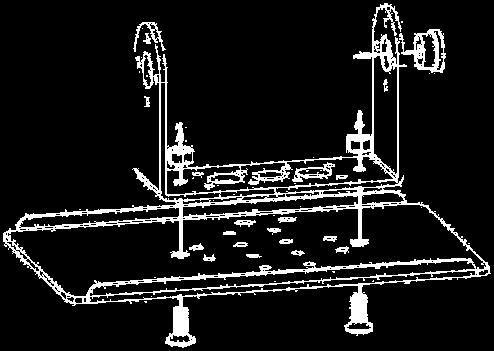
19 B. Connecting Top Board with Module i. Assemble Top Board with Command Board Insert Screw C into 4 holes of Command Board and fix them with Nut A from below as illustrated. Pass 4 screws through Top Board. Add a Nut A on each of the protruding screws under the Top Board; after turning them up with hand, secure them with long nose pliers. 15


20 ii. Assemble Main Board with Servo Runner A Insert Screw C into 4 holes of Servo Runner A and fix them with Nut A, in the direction as illustrated. Pass the 4 screws through Top Board. Add a Nut A on each of the protruding screws under the Top Board; after turning them up with hand, secure them with pointed pliers. 16


21 iii. Install servos and connect with Main Board Place a servo in each top Servo Plate of the left and right leg frames. Turn the leg frames outward 90 degrees as shown for easy installation. Fix servos to respective Servo Plates; insert Screw A with Washer A downwards, passing through servo and then Servo Plate and then fix the screw with a Nut A on the inside of Servo Plate. Place Main Board on top of the just assembled servos, and lock with Screws F. Note that Screw F is of self-tapping. Use a lower torque if a powered screwdriver is used. Lock the two diagonal screws first, check the screw hole alignment and then lock another two screws. Add Screw B to Top Board and lock with the copper post. Place Top Board on top of the 8 screw holes that fix the servos; from lower side of Main Board, secure Nut A with long nose pliers. Insert BC1 into Leg Frame according to pin assignment; pull or push it vertically to avoid slanting/damaging pins. Connect Command Board and Servo Runner A with Command Board Power Line. Make sure red line is connected to + and black to -. Incorrect connection may damage the module. Use correct Servo Power Line to connect with the Servo Board; select corresponding connector for the battery pack. Ensure correct polarity; incorrect connection may damage the module. Connect cmdbus cable to Command Board and Servo Runner A. Maker the red line connects to Vin. Incorrect connection may damage the module. 17


22 Install the rest 10 servos respectively into each Servo Plate and fix them with Screw A, Washer A and Nut A. Then lock U-shape Bracket onto servo with Screw E. While locking these screws, make sure the each U-shape Bracket is either parallel or perpendicular to the servo. DO NOT disturb the disk before fixing it. 18

23 Connect the control line of each servo to the corresponding pins on the Servo Module. Make sure that settings of servo numbers in the program conform to servo numbers on the Servo Module; only the following connection may ensure movements as programmed in the example. No. 0 No. 8 No. 1 No. 9 No. 2 No. 10 No. 3 No. 11 No. 4 No. 12 No. 5 No. 13 A Servo number is provided beside each Servo Module. Note that the white wire is signal, red the power and black the Ground. Connect them as indicated on the module, to avoid any damage of the module. 19
24 iii. Fine-tuning initial value of servo There might be some positioning errors in each servo that are possibly caused by installation or mechanical errors. Therefore, before assembling and installing, it is necessary to perform a two-step adjustment so as to allow the follow-up operations to be positioned correctly. A. Structure fine-tuning: Prior to the final step of installation, the disks of all servos are not yet fixed to the structure. You may unscrew the central black screw and adjust position of the disk now. Connect all servos to the Servo Module and connect to the power supply. Referring to servo calibration procedures, let all servos move to their center point respectively. Check if all screw holes align with holes on the disk. If not, unscrew the central screw and pull up the disk, align disk holes to holes on the structure and lower the disk. Both the PC and aluminum are flexible to a certain extent. In case hole positions on the PC board misalign with the hole positions of servos, just slightly pull PC board up and adjust the disk, by lifting it up, to a desired angle and replace it. Align holes of all 12 servos one by one, and then proceed with final fixing of the installation. B. Software fine-tuning: After completing structure fine-tuning and fixing disks (the final step of installation), proceed with software fine-tune program. Enter fine-tune value of each servo respectively and adjust all motors to their desired positions. In case satisfactory result cannot be achieved within the limit range (127~-128), go back to structure fine-tune and readjust the structure. Make sure all disk screws are tightened and all servos are within the tolerance range while performing software fine-tuning. 20


 While connecting the power line, please notice the polarity. Connect the two red wires together. B_4.")
25 B_1. Connect the PC and the BASIC Commander on the robot with the USB cable The connectors at the two ends of the USB cable are of different sizes, so please connect the smaller one to the BASIC Commander. B_2. Make sure the DIP switch on the Command Board is at the 0 position. If not, please poke it to the 0 position. B_3. Connect the power line of the servo to the power supply (Please make sure that the voltage and current from the power supply are within the range required by the servo. After connecting the power line, the servo will make a transient motion due to receiving the switch surge, which is normal. While connecting the power cord, please pay attention not to place your hands within the space where the servo will move into to avoid being clamped.) While connecting the power line, please notice the polarity. Connect the two red wires together. B_4. Start InnoBASIC Workshop Click the application under the innobasic Workshop folder to start the innobasic Workshop. B_5. Click Tools in the menu bar on the top 21

 Click Motion Editor to start the Motion Editor. If this message appears, it means that the USB cable is not connected correctly. B_7.")
26 After clicking each item, a pull-down menu with more function items will be displayed. Please click the Tools" item now. B_6. Click the Motion Editor in the pull-down menu (If a warning window appears, it means that the BASIC Commander is not correctly connected. Please check if the USB cable is connected or unplug and then plug it again to ensure a correct connection. Exit the Motion Editor and then re-click this button.) Click Motion Editor to start the Motion Editor. If this message appears, it means that the USB cable is not connected correctly. B_7. If the connection is correct, the message Downloading servo manager... will be displayed on the PC screen meaning that the program is being downloaded. Please poke the DIP switch on the Command Board to the 1 position and wait a moment. The message means that the program is being downloaded. Please do not remove the USB cable. B_8. After the downloading is complete, a notification window will appear. Please make sure that each servo has been connected correctly. After confirming all the connections, please click OK. (If Cancel is clicked, the Motion Editor will be closed. If there is any component is incorrectly connected at this moment, please click Cancel to terminate the program.) 22


27 The message appears for notifying the download is complete. Please make sure that the servos have been connected correctly at the specified positions. B_9. Please pay attention not to place your hands within the space where the servos may move into to avoid being clamped. Please check the checkbox for activating the servos on the left side to move all the servos to their central points. Please note that the number next to it should be If it is not 1500, please click the number directly, enter the number 1500 and then click Enter. B_10. Click the Adjust Offset button at the upper right corner. B_11. If the fine tune values are not yet stored, the Filename will be Untitled. The user can specify a preferred name while storing the file. B_12. Observe the servo that requires the fine tune and click the corresponding arrow buttons. The servo will rotate in the selected direction. Please make 23


28 sure that the rotation is in the correct direction. If the reverse rotation is required, click the opposite arrow button. Adjust each servo to its central point one by one. The left/right arrow buttons can be used to rotate the servo clockwise or counterclockwise. Please observe the rotation of the servo to the required central position. Then adjust the next servo. B_13. Please note the values after fine tune. Click Save, select the location for storing the file, enter a preferred filename, and then click OK to save the values in the PC. If it is required to query or download the values, click Load to read out the values. Please enter a preferred name in the File name and then click Save. 1 2 After the file is successfully stored, the filename of the last stored file will be displayed in the Filename. B_14. Click the Close button at the lower right corner to close the window. 24
29 Click the Close button to close the window. B_15. After returning the Edit Servo Motion window, click the Exit button at the lower right corner to close the fine tune operation. Click the Exit button to close the Motion Editor. 25
30 iv. Perform Demonstrative Motions 4_1. Please copy the folder 12-DOF Bipedinno Doc to the PC. 4_2. In the InnoBASIC Workshop, click Tools in the menu bar on the top. 4_3. Click Motion Editor in the pull-down menu. 4_4. Click the button Match at the bottom of the Motion Editor. 26


31 4_5. Click the Browse button at the lower left corner. 4_6. Set the Browse for Folder location to the 12-DOF Bipedinno frame folder under the 12-DOF Bipedinno Docs folder and then click the OK button. 1 The selected folder will be highlighted. Please make sure that the selected folder is 12-DOF Bipedinno frame. 2 4_7. Please click the 12-DOF Bipedinno frame0.frm below the motion files on the left side, click the Frame 0 under the Module 0 and then click the >> button. 27
32 1 2 Before clicking the >> button to download the motion file into the module, please make sure that the Frame 0 under the Module 0 has been selected and highlighted. 3 4_8. Make sure that the Frame 0 below the Module 0 has become 12-DOF Bipedinno frame0.frm. After the download is complete, the original text Frame 0 will turn into 12-DOF Bipedinno frame0.frm. 4_9. Now click the 12-DOF Bipedinno frame 1 below the Frame Files and Frame 1 below the Module 0 as the two steps describe above. Repeat the operation for all the motions till Frames 0-11 have been downloaded to the corresponding frames _10. After all the download operations are complete, it is clear that all the motions above Motion 12 and below the Module 0 have been changed to the 28

33 corresponding motions. Please make sure that first 12 Frames have been successfully downloaded. 4_11. After the verifying the operations, click the Close button at the lower right corner to close the window for setting the corresponding motions. 4_12. In the Edit Servo Motions window, click the Exit button at the lower right corner to close the Motion Editor. 29


34 4_13. Click File in the menu bar and click Open. 4_14. Please select the 12-DOF Bipedinno Walk Demo in the folder and click Open. 1 The selected folder will be highlighted. Please make sure that the selected folder is 12-DOF Bipedinno Walk Demo. Click the Open button to download the program into the innobasic Workshop for editing or creating motions. 2 30
35 4_15. Move to the 27 th line of the program to see the Initial Function. (To move within the program, the user can also click the mouse button at any position in the program and then rotate the mouse wheel to scroll the program page.) The number on the left side represents the line number of the program. The Function starts at Sub and ends at End Sub within which the operations are defined to store the fine tune values into the module. At the beginning of each program, it is necessary to set the fine tune values. 4_16. Update the fine tune values, which are recorded during the software fine tune, into the Initial Function to replace the original values of 0. The SetPosOffset command has two parameters: one is the Servo ID and the other is the fine tune value. Please enter the fine tune value according to the value recorded for each servo ID. The number in the figure is arbitrarily defined, Please do not enter the same number as shown in the figure. 4_17. Poke the DIP switch from the 1 position to the 0 position to prevent the robot from starting the motion directly after the program is successfully created. 1

36 4_18. Press the Build button and wait until the download is complete. If the user is not sure about the function of each button, the user can move the mouse pointer over the image. After a while, the English name will automatically appear. After click the "Build" button, the program will be downloaded into the BASIC Commander and stored automatically. According to the layout, the "Build" button may appear at different position. After the download is complete, the output window will display the used memory space. If there is any error, it will be displayed in the output window. Please make sure that no error is displayed in the output window. 4_19. Remove the USB cable that has been connected to the robot and place the robot at a location prepared for performing the motion operations. 4_20. Poke the DIP switch from the 0 position to the 1 position. The robot will perform a forward movement according to the demonstrative program. 1
Mini Hexapodinno. 18-DOF Robot
 Mini Hexapodinno 18-DOF Robot Instruction Manual Version 1.11 Trademark Innovati,, and BASIC Commander, are registered trademarks of Innovati Inc. InnoBASIC and cmdbus are trademarks of Innovati Inc. Copyright
Servo Commander 32 User s Guide
 Servo Commander 2 User s Guide 2 Servo Control Outputs Version: 1.2 Innovati s Servo Commander 2 module incorporates BASIC Commander BC1 and two Servo Runner A modules. It saves area occupied by the control
Assembly Guide Robokits India
 Robotic Arm 5 DOF Assembly Guide Robokits India info@robokits.co.in Robokits World http://www.robokitsworld.com http://www.robokitsworld.com Page 1 Overview : 5 DOF Robotic Arm from Robokits is a robotic
Servo Runner A User s Guide
 Servo Runner A User s Guide Version 1.2 Innovati s Servo Runner A module is capable of controlling up to 16 servos simultaneously. By providing integrated commands, this allows the user to determine the
3.2.3 Rear Door Window and Quarter Window Carrier Assembly
 Tighten all bolts. Tighten bolts marked -1- and -2- in specified sequence. Tightening torque: 8 Nm Remaining bolts can be tightened in any sequence. Insert door window -3- through window recess without
Maintenance Information
 47104302 Edition 1 November 2012 Cordless Drill/Driver QX Series Maintenance Information Save These Instructions Tool Diagnosis 1. Before servicing this unit, you will need a fully charged battery of known
1. ASSEMBLING THE PCB 2. FLASH THE ZIP LEDs 3. BUILDING THE WHEELS
 V1.0 :MOVE The Kitronik :MOVE mini for the BBC micro:bit provides an introduction to robotics. The :MOVE mini is a 2 wheeled robot, suitable for both remote control and autonomous operation. A range of
Installing a 3 Indexer: Desktop Tools
 888-680-4466 ShopBotTools.com Installing a 3 Indexer: Desktop Tools built after October, 2012 Copyright 2016 ShopBot Tools, Inc. page 1 Copyright 2016 ShopBot Tools, Inc. page 2 Table of Contents Overview...5
Installing the 3 Indexer: PRS Standard Tools
 888-680-4466 ShopBotTools.com Installing the 3 Indexer: PRS Standard Tools Copyright 2016 ShopBot Tools, Inc. page 1 Copyright 2016 ShopBot Tools, Inc. page 2 Table of Contents Route Cable into Box...5
Vinyl Cutter Instruction Manual
 Vinyl Cutter Instruction Manual 1 Product Inventory Inventory Here is a list of items you will receive with your vinyl cutter: Product components (Fig.1-4): 1x Cutter head unit complete with motor, plastic
Quick Start Guide. Contents
 1 Quick Start Guide Contents Powering on the Machine Login/Password Entry Jaw Set Up High Security Cut by Code High Security Jaw Set Up Edge Cut Cut by Code Edge Cut Cut by Decode Cutter Replacement Tracer
EPPA2-KIT DUAL MONITOR ARM CONVERSION
 EPPA2-KIT DUAL MONITOR ARM CONVERSION EPPA2-KIT Rev A 10/17 Model EPPA2-KIT-XXX ASSEMBLY AND ADJUSTMENT EPPA2-KIT PARTS AND TOOLS PLEASE REVIEW these instructions before beginning the assembly and adjustment
Z-Truck Up-and-Down Motion. Y-Truck Side-to-Side Motion. Head. Squaring Plate. Sliding Plate FIGURE 1: THE CARVEWRIGHT MACHINE
 Setup and use of CarveWright CO2 Powered Dragster Jig The CO 2 powered Dragster Jig will arrive from the factory fully assembled, calibrated, and squared. In order to get the best results, your CarveWright
TM5. Guide Book. Hardware Version: 2.00 Software Version: 1.62
 TM5 Guide Book Hardware Version: 2.00 Software Version: 1.62 ii Release Date : 2017-07-10 The information contained herein is the property of Techman Robot Corporation (hereinafter referred to as the Corporation).
DPM Kit DK-1. Using the DPM Kit
 DPM Kit DK-1 Using the DPM Kit To ensure safe usage with a full understanding of this product's performance, please be sure to read through this manual completely. Store this manual in a safe place where
V-MOTION LITE USER GUIDE. Rat Rig All rights reserved.
 V-MOTION LITE USER GUIDE Rat Rig 2017. All rights reserved. PACKAGE CONTENTS 1 1x V-Motion Motor 2 1x Belt 3 1x 3mm Hex Key 4 1x AA Battery Pack (for 8x AA batteries)* 5 1x V-Motion Controller 6 2x Knob
VSD-6500 Frame Exploded View LIFT P/N
 VSD-6500 Frame Exploded View LIFT P/N 511-65075-01 34 34 45 96 55 108 22 9 7 55 54 34 89 90 56 24 99 23 111 SEE SHEET 4 34 91 45 106 20 55 26 68 95 5 55 109 7 22 8 54 53 71 66 5 95 31 58 6 6 46 60 73 25
InnobotTM User s Manual
 InnobotTM User s Manual Document Rev. 2.0 Apr. 15, 2014 Trademark Innovati,, and BASIC Commander are registered trademarks of Innovati, Inc. InnoBASIC, cmdbus, Innobot and Explore Board are trademarks
ABM International, Inc.
 ABM International, Inc. Lightning Stitch required 1 1.0: Parts List head and motor assembly (Qty. 1) Reel stand (Qty. 1) Needle bar frame clamp (Qty. 1) Motor drive (Qty. 1) 2 Cable harness with bracket
Band-Master ATS Nano Pneumatic Banding Tool Operating Instructions
 Band-Master ATS 601-118 Nano Pneumatic Banding Tool CONTENTS 601-118 Overview... 3 Safety.... 5 Initial Tool Set-up... 5 Regulator assembly mounting... 5 Attach tool head to regulator.... 6 Operating instructions...
For additional assistance call
 The following pages will help guide you through the process of assembling your new 48 custom prize wheel. Choose an assembly area with plenty of room to lay your pieces on the floor and also a bench or
Strata. urniture. Adriana Instructions. Parts in the Arm Box: Parts in the Body Box: Watch our assembly videos at
 1A Watch our assembly videos at www.strataf.com/videos Parts in the Arm Box: Arm - Outside View Arm - Inside View 1B Parts in the Body Box: Back Deck x 1 Seat Deck x 1 with the Feet attached Back Panel
Elimination of Elevator Bounce
 For the Agilent Archon Autosampler Rework Instructions CAUTION This kit is intended for use by Agilent Service personnel only. Elevator Removal 1 Open top cover. 2 Open front lower door. 3 Remove vial
Installing Brackets to Minimize Distortion in Your SMART Board 685ix Interactive Whiteboard System s Projected Image
 UX60-RFK-685 Installing Brackets to Minimize Distortion in Your SMART Board 685ix Interactive Whiteboard System s Projected Image Follow these instructions to install brackets on your SMART Board 685ix
HQ Hideaway. Installation and Operation Version 2.2, April 2015 Part # QT40100
 HQ Hideaway Installation and Operation Version 2.2, April 2015 Part # QT40100 Copyright 2015 Handi Quilter, Inc. All rights reserved. Printed in the U.S.A. Table of Contents Page Overview 3 To install
Range height adjustable assembly
 Table of contents Digital handset operation 3 Height adjustable bench kit 4-5 Cable carrier 6 Ganging tray and ganging rail 7 Height adjustable return frame kit 8 Cable entry pole 9 24 and 30 d worksurfaces
ABM International, Inc. Navigator Assembly Manual
 ABM International, Inc. 1 1.0: Parts List Tablet (Qty. 1) Tablet mount (Qty. 1) NOTE: Mount may appear and operate different then image below Control Box (Qty. 1) Motor Power Supply (Qty. 1) 2 X-axis motor
MOTOR REPLACEMENT : STEP BY STEP.
 (D) REPLACEMENT : STEP BY STEP. (V) Adjustment screw (Allen key 3/16 ) (E) (U) (I) Tightening screw (Allen key 5/32 ) Blocking screw (H) (Allen key 5/32 ) (G) (Y) (T) (ZZ) (Z) (K) (X) (L) (S) (W) (R) (Q)
3DOF Leg Kit Assembly Guide VERSION 1.0
 3DOF Leg Kit Assembly Guide VERSION 1.0 WARRANTY CrustCrawler warrants its products against defects in materials and workmanship for a period of 30 days. If you discover a defect, CrustCrawler will, at
Start Here. Installing your Microtek ScanMaker 9800XL Plus PC:
 Start Here Installing your Microtek ScanMaker 98XL Plus Step : Unpack Contents. Optional package items depend on the scanner configuration that you purchased. Unpack your scanner package and check for
RPMSP Series Installation Guide
 RPMSP Series Installation Guide Contents 1. Overview... page 1 2. Unpacking the Projector...2 3. Projector Configuration...2 4. Projector Throw Distance and Mounting...9 5. Projection Lens Focus...9 6.
User Instructions Multiline Otter Scoreboard Caddy Assembly
 List of parts: User Instructions Multiline Otter Scoreboard Caddy Assembly Single Caddy Double Caddy 1 1 Base assembly with attached wheels 2 4 1 1 2 4 4 8 10 20 12 Uprights (60 or 74 aluminum extrusion)
Standard Operating Procedure
 RIT MULTIDISCIPLINARY SENIOR DESIGN 2010 Standard Operating Procedure Baja Water Propulsion Test Stand This SOP specifies how to assemble, use, troubleshoot, and disassemble the water propulsion system
ROBOT KR 350. Installation, Connection, Exchange. Ro/Me/03/ en. 1of 26
 ROBOT KR 350 Installation, Connection, Exchange 1of 26 e Copyright KUKA Roboter GmbH This documentation or excerpts therefrom may not be reproduced or disclosed to third parties without the express permission
Build your own. Pack. Stages 19-22: Continue building Robi s left arm
 Build your own Pack 06 Stages 19-22: Continue building Robi s left arm Build your own All rights reserved 2015 Published in the UK by De Agostini UK Ltd, Battersea Studios 2, 82 Silverthorne Road, London
Durst Laborator 138 S
 Durst Laborator 138 S -I- G139 Durst Laborator 138 S Durst Laborator G 139 Servicing instructions L 1 3 8 S G 139 - Replacing the counterweight spring The special tool required for this purpose is supplied
Content Components... 1 i. Acrylic Plates... 1 ii. Mechanical Fasteners... 3 iii. Electrical Components... 4 Introduction... 5 Getting Started... 6 Ar
 About r Preface r is a technology company focused on Raspberry Pi and Arduino open source community development. Committed to the promotion of open source culture, we strive to bring the fun of electronics
Installation Instructions for Vista Air Vertically Folding Walls
 Installation Instructions for Vista Air Vertically Folding Walls Use these instructions in conjunction with your shop drawings to see the specifics that are particular to the model you are installing.
Hatch Whiteboard: Portable Stand Installation Instructions
 Hatch Whiteboard: Portable Stand Installation Instructions Remove Projector Wall Plate 1. Open the wall mount for the projector. 2. Remove the shipping screw from the front center of the mount arm. 1 P
Assembly Guide for Printrbot - Simple Maker s Edition 1405
 Assembly Guide for Printrbot - Simple Maker s Edition 1405 Last update: March 2016 Please Note: be careful on the steps that are underlined 1 Contents Tools Needed:... 3 First step: Check components and
V Installation instructions, accessories. Auxiliary seat. Volvo Car Corporation Gothenburg, Sweden V70 (00-08) 2002
 2002") Installation instructions, accessories Instruction No 8624018 Version 1.3 Part. No. 30749269, 30749270, 30749271, 30749272, 30749273, 30749274 Auxiliary seat M8901699 Volvo Car Corporation Auxiliary seat-
Installation instructions, accessories Instruction No 8624018 Version 1.3 Part. No. 30749269, 30749270, 30749271, 30749272, 30749273, 30749274 Auxiliary seat M8901699 Volvo Car Corporation Auxiliary seat-
model tsa-sa48 Sliding Crosscut Table installation guide
 model tsa-sa48 Sliding Crosscut Table installation guide A Note About Color Variations Among Anodized Aluminum Components Congratulations on the purchase of this SawStop Sliding Crosscut Table. We at SawStop
Installation and Assembly - Universal Articulating Swivel Double-Arm for 42" - 60" Plasma Screens
 Installation and Assembly - Universal Articulating Swivel Double-Arm for 42" - 60" Plasma Screens Models: PLAV 70-UNL, PLAV 70-UNL-S PLAV 70-UNLP, PLAV 70-UNLP-S R This product is UL Listed. It must be
RANGE DIGITAL HANDSET OPERATION. 1. Panel. 2. Initialization Procedure. 3. Move Up & Down. 4. Set Memory Positions. 5. Move to the Memorized Positions
 INSTRUCTION SHEET #2577INS PART #1730534 DIGITAL HANDSET OPERATION OPERATION INSTRUCTIONS 1. Panel 1 Button: Preset 1 2 Button: Preset 2 3 Button: Preset 3 S Button: Select Display: Reads in 1 / 2 " Increments
FitWork Walkstation Series 7 AdjusTables
 FitWork Walkstation Tools Required: #2 Phillips Bit with Extension Page 1 of 20 A7TG660606H A7TR663232H FitWork Walkstation 4mm Hex Head Bit A7TG660632H A7TR383030H www.details-worktools.com A7TG663206H
Maintenance Information
 16601023 Edition 2 January 2014 Air Impact Wrench 2705P1 Maintenance Information Save These Instructions Product Safety Information WARNING Failure to observe the following warnings, and to avoid these
Fixed Wall Arm. Installation Guide. Part number Rev E 2012 PolyVision Corporation All rights reserved
 Fixed Wall Arm Installation Guide Part number 2002003-001 Rev E 2012 PolyVision Corporation All rights reserved Table of contents Important Safety Instructions... 3 Overview... 4 Important considerations...
Replacing the Reciprocator on the SWF Compact Series Machine (601C and 1201C)
") Follow the instructions below to replace the reciprocator in the SWF Compact series machines. The tools required can be found in the tool kit that came with the machine. Preparation 1. First, place the
Follow the instructions below to replace the reciprocator in the SWF Compact series machines. The tools required can be found in the tool kit that came with the machine. Preparation 1. First, place the
Door window. Front door window, assembly overview
 64-50 Door window Front door window, assembly overview 1 - Window channel Pushed onto flange 2 - Door window Removing Page 64-52 Adjusting Page 64-53 3 - Door 4 - Outer window channel Pushed onto flange
Build your own. Stages 47-50: Continue building up Robi s left leg
 Build your own Pack 13 Stages 47-50: Continue building up Robi s left leg Build your own All rights reserved 2016 CONTENTS Published in the UK by De Agostini UK Ltd, Battersea Studios 2, 82 Silverthorne
Arc Trainer Main Frame Assembly
 Arc Trainer Main Frame Assembly Kit No. 610AK019-4 Kit No. 630AK019-4 NOTE: This instruction sheet describes how to replace the main frame assembly in the Arc Trainer 610A. Tools Required 3/16 Allen wrench
ABSL Model Background Stand
 ABSL Model Background Stand Product Overview: The Ravelli ABSL model background stand is adjustable up to 13' tall by 15' wide. It is comprised of two tripod stands and five 3 cross bar sections and includes
Ohbot. Eyes turn. servo. Eyelids open. servo. Head tilt. servo Eyes tilt. servo. Mouth open servo. Head turn servo
 Making Instructions Ohbot Ohbot has six servo motors. The servos allow each part of the face to be positioned precisely. Eyelids open servo Eyes tilt servo Eyes turn servo Head tilt servo Mouth open servo
1 of 2 3/3/2017 4:49 PM
 1 of 2 3/3/2017 4:49 PM Front Door Window, Assembly Overview 1 - Window guide - Inserted on flange 2 - Door 3 - Inner window recess seal - Inserted on flange 4 - Bolt - 20 Nm 5 - Carrier assembly - Window
Problem/Procedure Description. Requirements. Problem/Procedure Solution. How-To Document. Updated on: 11/13/2008 By:Christopher Ware
 Problem/Procedure Description Performing maintenance on 95s, 95sII and H100 Requirements Ball Bearing Grease (LPKF P/N 106976) Tri-Flow Teflon lubricant aerosol. 3-in-1 Multi-purpose Oil Electronic Component
REPAIR INSTRUCTIONS. Cat. No Cat. No MILWAUKEE ELECTRIC TOOL CORPORATION. SDS Max Demolition Hammer. SDS Max Rotary Hammer
 Cat. No. 9-0 SDS Max Demolition Hammer Cat. No. -0 SDS Max Rotary Hammer MILWAUKEE ELECTRIC TOOL CORPORATION W. LISBON ROAD BROOKFIELD, WISCONSIN 00-0 8-9-0 d 000 8-9-0 d Special Tools Require Forcing
The ideal K-12 science microscope solution. User Guide. for use with the Nova5000
 The ideal K-12 science microscope solution User Guide for use with the Nova5000 NovaScope User Guide Information in this document is subject to change without notice. 2009 Fourier Systems Ltd. All rights
FUNCTIONAL DESCRIPTION
 FUNCTIONAL DESCRIPTION NOTE: The information contained in this Instruction Manual is designed to assist you in the safe operation and maintenance of the power tool. Some illustrations in this Instruction
Tools Needed Hardware Provided (per shade) Hardware Needed
 Hardware Needed") Baby Grande or Grande Motorized (XQ5 Premium) Shade with Cables and Housing Installation Instructions Tools Needed Hardware Provided (per shade) Hardware Needed Drill 3/8 Metal Drill Bit Measuring Tape
Baby Grande or Grande Motorized (XQ5 Premium) Shade with Cables and Housing Installation Instructions Tools Needed Hardware Provided (per shade) Hardware Needed Drill 3/8 Metal Drill Bit Measuring Tape
CONTENTS PRECAUTIONS BEFORE STARTING OPERATION PREPARATION FOR OPERATION CAUTIONS ON USE OPERATION
 CONTENTS PRECAUTIONS BEFORE STARTING OPERATION ------------------------------------- 1 PREPARATION FOR OPERATION 1. Adjustment of needle bar stop position ---------------------------------------------------------
Lead Screw Upgrade. How to upgrade your ROBO R1 to the new Lead Screw Upgrade Pack. Written By: Harrison Team RoBo 3D
 Lead Screw Upgrade How to upgrade your ROBO R1 to the new Lead Screw Upgrade Pack. Written By: Harrison Team RoBo 3D 2017 guide.robo3d.com Page 1 of 14 Step 1 Lead Screw Upgrade Begin by powering off and
Sliding Crosscut Table installation guide
 Sliding Crosscut Table installation guide model tsa-sa48 A Note About Color Variations Among Anodized Aluminum Components Congratulations on the purchase of this SawStop Sliding Crosscut Table. We at SawStop
Build your own. Stages 7-10: See Robi s head move for the first time
 Build your own Pack 03 Stages 7-10: See Robi s head move for the first time Build your own All rights reserved 2015 Published in the UK by De Agostini UK Ltd, Battersea Studios 2, 82 Silverthorne Road,
Removing outter components
 Y Axis Motor Replacement Replacing the Y axis motor is a process that requires the individual to be somewhat mechanically inclined and can follow detailed instructions. If any of the following steps are
Installation and Assembly - Universal Articulating Swivel Double-Arm for 42" - 60" Plasma Screens
 Installation and Assembly - Universal Articulating Swivel Double-Arm for 42" - 60" Plasma Screens Models: PLAV 70-UNL, PLAV 70-UNL-S PLAV 70-UNLP, PLAV 70-UNLP-S R This product is UL Listed. It must be
Laminate Cabinet Installation Instructions
 Laminate Cabinet Installation Instructions www.easygaragestorage.com/installation How To Use These Instructions Thank you for your purchase! Please read each step of this manual thoroughly to ensure proper
v1.0 ASSEMBLY GUIDE Mia Wide Bookcase
 v1.0 ASSEMBLY GUIDE Mia Wide Bookcase Components Upon unpacking your bookcase from it s delivery box, you should have the pieces shown. Follow the steps on the next pages to assemble your new bookcase.
Thank you for purchasing out product! *Please read these instructions and follow them step by step. *
 Page 1 of 7 AD17 AA DS 4 X 16 T12 Thank you for purchasing out product! *Please read these instructions and follow them step by step. * STEP 1. Slide two support posts (REF. # 24) into the two outside
Stainless Steel Bench Stand
 Installation Manual Stainless Steel Bench Stand Product(s): 29600 29601 51229 2016 by Fairbanks Scales, Inc. Revision 2 02/16 All rights reserved. Amendment Record STAINLESS STEEL BENCH STAND Document
Installation and Assembly: Articulating Swivel Arm for 37" - 60" Flat Panel Displays
 Installation and Assembly: Articulating Swivel Arm for 37" - 60" Flat Panel Displays Models: PLA60, PLA60-S, PLAV60, PLAV60-S Max UL Load Capacity: 175 lb (79 kg) 2300 White Oak Circle Aurora, Il 60502
ASSEMBLY GUIDE. Mia Narrow Bookcase
 ASSEMBLY GUIDE Mia Narrow Bookcase Components: Upon unpacking your bookcase from it s delivery box, you should have the pieces shown. Follow the steps on the next pages to assemble your new bookcase. Step
MatterHackers. How to Install an E3D v6 HotEnd on a Lulzbot. Upgrade your TAZ with a shiny new E3D hotend. Written By: Ryan Lutz
 MatterHackers How to Install an E3D v6 HotEnd on a Lulzbot TAZ 5 Upgrade your TAZ with a shiny new E3D hotend. Written By: Ryan Lutz 2017 matterhackers.dozuki.com Page 1 of 21 INTRODUCTION NOTE: This guide
Model:CB-MRC. Instruction Manual of Mini Recessed Motorized Screen
 GRANDVIEW REPRODUCING GENUINE COLORS GRANDVIEW REPRODUCING GENUINE COLORS Instruction Manual of Mini Recessed Motorized Screen Grandview Crystal Screen Canada Ltd. #11-3751 North Fraser Way, Marine Way
DIY KITS FRAME KIT. Thank you for purchasing a 3DR Y6 DIY Kit!
 DIY KITS Y6 FRAME KIT Thank you for purchasing a 3DR Y6 DIY Kit! These instructions will guide you through assembling and wiring your new autonomous multicopter. CONTENTS Your 3DR Y6 Kit contains: 35 mm
Baby Grande or Grande Crank Shade with Cables and Housing Installation Instructions
 Baby Grande or Grande Crank Shade with Cables and Housing Installation Instructions Tools Needed Drill 3/8 Metal Drill Bit Screwdriver (Flat & Phillips) Measuring Tape Pencil 4 Level Plumb Line ¼ Masonry
 Menu Board Tilt or Fixed Mount Installation Instructions MDS1T-200, MDS1T-300, MDS1T-400 MDS2T-200, MDS2T-300, MDS2T-400 MDS3T-200, MDS3T-300, MDS3T-400 MDS4T-200, MDS4T-300, MDS4T-400 MDS5T-200, MDS5T-300,
TP3100(EA) Series TP3123(EA) / TP3126(EA) / TP3129(EA) / TP3132(EA)
 Series TP3123(EA) / TP3126(EA) / TP3129(EA) / TP3132(EA)") PEDAL TIMPANI TP3100(EA) Series TP3123(EA) / TP3126(EA) / TP3129(EA) / TP3132(EA) Owner s Manual Thank you for purchasing a Yamaha Timpani. Please read through this manual carefully as it contains important
PEDAL TIMPANI TP3100(EA) Series TP3123(EA) / TP3126(EA) / TP3129(EA) / TP3132(EA) Owner s Manual Thank you for purchasing a Yamaha Timpani. Please read through this manual carefully as it contains important
SmartCrystal Diamond
 model VPSP-08000 VPSP-08100 VPSP-08200 www.volfoni.com This document is the property of the Co VOLFONI and may not be reproduced or disclosed without permission. 1 TABLE OF CONTENTS INTRODUCTION ---------------------------------------------------------------------------------------------------------------------------------------------------------------------------------------------
Hydrajaws Safety Lifeline Tester
 Hydrajaws Safety Lifeline Tester Operating Instructions HYDR AJAWS LIMITED Hydrajaws Safety Lifeline Tester 4 5 1 6 7 2 3 9 10 8 12 11 TECHNICAL SPECIFICATIONS Load Gauges Range available: Analogue: 0-25kN/lb/f
Treasure Cove Metal Detector
 Treasure Cove Metal Detector Fortune Finder 1023 OWNER S MANUAL www.treasure-cove.com 805-658-2328 With your 1023 metal detector, you can hunt for coins, relics, jewelry, gold, and silver just about anywhere,
Customer Notice: Congratulations again on your SawStop purchase, and thank you! -SawStop Tualatin, OR
 Customer Notice: Congratulations on the purchase of this Sliding Crosscut Attachment. As the owner of a SawStop saw, you are familiar with our high standards for quality, fit and finish. Different from
Scorpion Antennas Controller. Instruction Manual. Firmware V11.8 November Please Read This Manual Completely Before Operating The Controller
 Firmware V11.8 November 2012 Please Read This Manual Completely Before Operating The Controller Contents Introduction:... 3 Installation:... 3 Using the Scorpion Antennas Controller... 5 Tuning Your Dipole...
Z14 MANUAL TÉCNICO TECHNICAL MANUAL
 Z14 MANUAL TÉCNICO TECHNICAL MANUAL Z14 TECHNICAL INSTRUCTIONS CONTENTS: 1.- Opening the machine 2.- Changing the bridge 3.- Checking if cleaning and greasing is needed 4.- Puller runner bolts 5.- Tray
Tapping Screw (W/Flange) 46 Cord Armor 47 Tube (D) 48 Cord. 45 Cord Clip. Tapping Screw (W/Flange) 10 Gear Cover Ass'y. 12 Socket (B) Ass'y
 46 Cord Armor 47 Tube (D) 48 Cord. 45 Cord Clip. Tapping Screw (W/Flange) 10 Gear Cover Ass'y. 12 Socket (B) Ass'y") W8VB The exploded assembly drawing should be used only for authoized service center. W8VB Item No. Part time 1 Magnetic Hex. Socket 2 Sub Stopper 3 O-Ring (S-16) 4 Locator (A) 5 Lock Sleeve (A) 6 O-Ring
W8VB The exploded assembly drawing should be used only for authoized service center. W8VB Item No. Part time 1 Magnetic Hex. Socket 2 Sub Stopper 3 O-Ring (S-16) 4 Locator (A) 5 Lock Sleeve (A) 6 O-Ring
Installation Tutorial
 Installation Tutorial 1. Remove the finger parts, if the film, tear off the surface of the film, the number of parts were 1 4 4 5 5 2. First assemble the big finger parts, use M2X3 screws, M2X6 copper
NETpodium Rack ( & ) INSTRUCTION SHEET Jan 2017 Rev B
 INSTRUCTION SHEET Jan 2017 Rev B") (1-1671405-1 & 1-1671405-2) 411-117000 Jan 2017 Rev B 1-1671405-2 1-1671405-1 1. Kit Content Bottom Frame Assembly Top Frame Assembly Carboard Stencil Vertical Profile Assembly Wire Basket Bracket Wire
(1-1671405-1 & 1-1671405-2) 411-117000 Jan 2017 Rev B 1-1671405-2 1-1671405-1 1. Kit Content Bottom Frame Assembly Top Frame Assembly Carboard Stencil Vertical Profile Assembly Wire Basket Bracket Wire
Due to possible damage in shipping, the vertical stop assembly has been removed from this machine.
 Due to possible damage in shipping, the vertical stop assembly has been removed from this machine. To assemble, insert the threaded rod through the shroud opening in the top of the machine. Start the four
5 Maintenance 5.1 Guideway and Wipers
 5 Maintenance 5.1 Guideway and Wipers 5.1 Page 26 of 41 The grinding carriage runs with hardened rollers on hardened steel straps (2). The steel straps (2) are positioned on the grinding bed (1) and tensioned
PULL-THRU USER S MANUAL
 PULL-THRU USER S MANUAL G14x Part # 310 120 177 G20 Part # 310 120 188 G20x Part # 310 120 186 G40x Part # 310 120 163 TABLE OF CONTENTS SECTION 1 PCB DESIGN AND MOUNTING SECTION 2 MOUNTING ADAPTER TO
Fletcher F-3000 / F-3100 Accessory Laser Kit
 Fletcher F-3000 / F-3100 Accessory Laser Kit Shown Assembled on F-3000 Machine Product Warranty The Fletcher-Terry Company warrants the product purchased to be free from defects in parts and workmanship
The Bowflex Revolution XP Home Gym Assembly Instructions. P/N: Rev ( /0 )
") P/N: 001-7057 Rev ( /0 ) The Bowflex Revolution XP Home Gym Assembly Instructions 2 Table of Contents Before You Start... 2 Tools You Will Need / Hardware Contents... 3 Box Contents... 6 Assembling Your
P/N: 001-7057 Rev ( /0 ) The Bowflex Revolution XP Home Gym Assembly Instructions 2 Table of Contents Before You Start... 2 Tools You Will Need / Hardware Contents... 3 Box Contents... 6 Assembling Your
V-Groover SIMPLEX INSTRUCTION AND OPERATION MANUAL M O DEL 703. For best results use only authentic Logan blades.
 www.logangraphic.com SIMPLEX M O DEL 703 INSTRUCTION AND OPERATION MANUAL For best results use only authentic Logan blades CAUTION: BLADES EXTREMELY SHARP Use replacement blades #1258 Logan Graphic Products,
CREW REAR DOOR KIT P/N APPLICATION BEFORE YOU BEGIN KIT CONTENTS. Verify accessory fitment at Polaris.com.
 CREW REAR DOOR KIT P/N 2883437 APPLICATION Verify accessory fitment at Polaris.com. BEFORE YOU BEGIN Read these instructions and check to be sure all parts and tools are accounted for. Please retain these
Assembly Instructions 10 X 10 Aluminum Roof Support
 Assembly Instructions 10 X 10 Aluminum Roof Support Aluminum Roof Support Bolt Package 16-5/16 X 2 ¼ SS Bolt 24-5/16 X 1 SS Bolt 40-5/16 SS Nylon Lock Nuts 16-5/16 SS Flat Washers 28-4 ½ Wood Screws 36-1
Installation Instructions
 Installation Instructions Ceiling Mount Bracket for DLP Based Projectors (for High Ceilings) Model No. ET-PKD100H Contents Important Safety Notice.................. 2 For DLP Based Projector: PT-D10000
WEIGHT ADJUSTABLE ESPREE. Model 2ESP-WA-C48- Model 2ESP-WA-C60- 2ESP-WA Rev B 8/17 ASSEMBLY AND OPERATION
 WEIGHT ADJUSTABLE ESPREE PNEUMATIC TABLE BASE 2ESP-WA Rev B 8/17 Model 2ESP-WA-C48- Model 2ESP-WA-C60- = SLV, BLK or WHT ASSEMBLY AND OPERATION PARTS AND TOOLS PLEASE REVIEW these instructions before beginning
Sales & Service. JFK - Just For Kids. sasportonline.com. 135 Forestview Road 7879 Will Rogers Blvd.
 Sales & Service sasportonline.com SA Sport (Canada) SA Sport (U.S.A.) 135 Forestview Road 7879 Will Rogers Blvd. P.O. Box 40 Fort Worth, Texas Orillia, Ontario USA 76140 Canada L3V 6H9 Telephone: (705)
Installation Instructions
 Installation Instructions Ceiling Mount Bracket (for Low Ceilings) Model No. ET-PKR100S Thank you for purchasing this Panasonic product. To customers The Installation Instructions is intended for use by
Instructions & Parts SM100B SM400 K025S1 K005
 Instructions & Parts SM100B SM400 K025S1 K005 Table of Contents 2 SM100B/SM400 Manual Engraver Machine Diagram Pantograph Operation Setup & Layout Engraving & Changing Cutters Adjusting Depth of Cut &
INSTALLATION TORSION SPRING FRONT OR REAR MOUNT LOW HEADROOM. 1 Cutting Vertical Track. 2 Fully Adjustable Jamb Brackets
 TORSION SPRING FRONT OR REAR MOUNT LOW HEADROOM Wayne Dalton, a division of Overhead Door Corporation P.O. Box 67, Mt. Hope, OH., 44660 Supplemental insert Copyright 2015 Wayne Dalton, a division of Part