Hydrajaws Safety Lifeline Tester
|
|
|
- Felicity Harmon
- 5 years ago
- Views:
Transcription


1 Hydrajaws Safety Lifeline Tester Operating Instructions HYDR AJAWS LIMITED
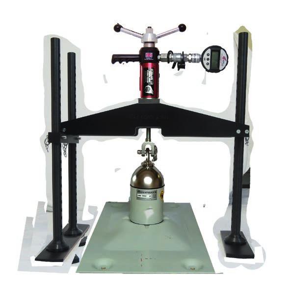
2 Hydrajaws Safety Lifeline Tester TECHNICAL SPECIFICATIONS Load Gauges Range available: Analogue: 0-25kN/lb/f Digital: 0-25kN Accuracy: Analogue to +/-2.5% fsd Digital to +/-0.5% fsd Indication of pull-out load Calibrated in kn Traceable UKAS calibration certificate supplied with each gauge Protective rubber cover (analogue only) Impact resistant glass (analogue only) Protection against sudden load relief (i.e. sudden failure of fixing) Analogue and Digital: peak hold memory Working Temperature: Analogue: -20 C to +60 C Digital: -30 C to +85 C Safety Lifeline Tester Parts 1. Hydrajaws Model 2000 Tester (only supplied in Kit 2) 2. Sliding test frame 3. 2 x M8 cap head screws 4. Holes for storing cap head screws 5. Spare cap head screw 6. Hinged lifeline tester clamp 7. Knurled Adaptor 8. Cable clamp (for use with swage joiner) 9. Extension plate insert 10. Test Frame extension bars 11. Extra extension legs 12. Slotted Collar Adaptor 2
3 GENERAL DESCRIPTION The Safety Lifeline Tester is a purpose made system for testing 8mm, 10mm, 12mm 3/8, 1/2 cable connections. It consists of a mechanical screw arrangement acting through a hydraulic load cell, which measures the load applied to the cable connection directly. The cable test frame requires the model 2000 tester meter with minimum 20kN gauge to operate it. A comprehensive range of accessories is also available, further increasing the scope of possible testing applications. USE OF THE TESTER AS DIRECTED The tester is intended for use by skilled personnel with the appropriate training and knowledge of the applicable safety precautions. CONTENTS Page Safety Lifeline Tester Parts 2 Technical Specifications 2 General description 3 Kit contents 4 1. GENERAL TESTING PROCEDURE - set up 5 2. Testing procedure of non Slip Indicator Swages 6 3. FITTING THE EXTENSION BARS 8 4. FITTING THE EXTRA EXTENSION BARS AND CLAMP 9 5. REMOVAL/REPLACEMENT OF CABLE ASSEMBLY GENERAL GUIDELINES FOR TESTING ASSEMBLY INSTRUCTIONS OF 600mm LOAD SPREADING BRIDGE CARE OF TESTER 8.1 Lubrication Oil refilling instructions Calibration It is essential that the operating instructions are read before the tester is operated for the first time. Always keep these operating instructions together with the tester. Ensure that the operating instructions are with the tester when it is given to other persons. SAFETY RULES Modification of the tester, or tampering with its parts is not permissible. Observe the information printed in the operating instructions applicable to operation care and maintenance. The tester and its accessories may present hazards when used incorrectly by untrained personnel or not as directed. Use only the genuine Hydrajaws accessories or ancillary equipment listed in the operating instructions. 3
 10.")
 14. Safety eyebolt 15. 25kN Gauge (Detachable with hydraulic coupler - Export only) 16.")
 22. 90mm Bolt Test Adaptor 23. 90mm M12 Ringbolt Adaptor Clevis 24a. Wall Tie Spacer Bridge 24b. with 100mm legs 25.")
 31. 3mm Ball Driver 32. Spare bridge screws & Allen key 33. Turning handle with integrated 22mm nut 34. Carry Case with foam filler 35.")

4 TESTER AND ACCESSORIES FULL KIT 2 CONTENTS: 1. Test Frame fitted with Extension Bars 2. Extra Extension bars 3. Extension plate insert a. - 8mm (fitted) b. - 12mm spare 4. Slotted Collar Adaptor 5. 22mm Ratchet Spanner 6. Cable Clamp bolts and Screws 7. 6mm Long series Allen key 8. 5mm Ball Driver 9. 2 x clamp Screws (spare M8 x 25) 10. Knurled Cable Adaptor 8mm (sited securely under the tester body). 10mm & 12mm optional. 11. Spare Collar Pins 12a. 2mm Allen key for pin collar 12b. Pin Collar & pin 13. Model 2000 Medium Duty Tester with coupler (Export only) 14. Safety eyebolt kN Gauge (Detachable with hydraulic coupler - Export only) Load Spreading Bridge with level bubbles 17. 6mm Ratchet 18. Adjustable Threaded Legs (3) 19. Swivel Feet (3) mm Hexagon Extension Legs (3) 21. M12 Locking Adaptor (shipped securely in tester jaw) mm Bolt Test Adaptor mm M12 Ringbolt Adaptor Clevis 24a. Wall Tie Spacer Bridge 24b. with 100mm legs 25. Spare battery 26. M12 Threaded Stud Adaptor Coupler 27. M12 Threaded Stud Adaptor* 28. M16 Threaded Stud Adaptor* 29. Oil bottle with coupler (Export only) 30. Piston key (Export only) 31. 3mm Ball Driver 32. Spare bridge screws & Allen key 33. Turning handle with integrated 22mm nut 34. Carry Case with foam filler 35. Operating Instructions 36. Calibration Certificate * 1/2 and 5/8 imperial equivalents Model Tester 36 HYDR AJAWS LIMITED Operating Instructions a 3a 3b b a b 17 Note: Kit illustrated is our Export Tester Kit 2 which features a body coupler, detachable gauge and oil replenisher bottle. UK specification kits feature a fixed gauge. 4
. 2.")
. 3.")
. 4. Remove the handles by unscrewing from the base using the 10mm wrench (fig 4). 5.")
5 1. GENERAL TESTING PROCEDURE - set up SETTING UP THE TESTER 1. Remove the 150 load spreading bridge with adjustable feet by unscrewing the two M4 cap screws on the underside of the unit (fig 1). 2. Make sure that the jaw on the tester is fully closed. Check this by looking at the mm scale on the main body of the tester which should be near the zero indicator (fig 2). 3. Remove the M12 round locking adaptor from the inside slot on the bottom of the portable tensioner by first unlocking/ slackening the allen screw (fig 3). 4. Remove the handles by unscrewing from the base using the 10mm wrench (fig 4). 5. Attach the gauge to the model 2000/C tester by pulling back on the body coupler and clicking into place. Turning the gauge will allow for easy reading (gauge only removable with coupler system fitted) (fig 5) Fig 1 Fig 2 Fig 4 Fig 3 Fig 5 5


6 2. Testing Procedure of non Slip Indicator Swages 1. Place the knurled adaptor into the end of the block and fix with the 3mm countersunk screw and collar (fig 6a). Do not over tighten the 3mm screw as the knurled adaptor should be free to rotate (fig 6b). 2. With the cable tester clamp side up, remove the 2 cap head screws using the 6mm Allen key. Pull and hinge the clamp open into it s vertical position (fig 7). 3. Slide the cable through the slots, close the clamp and replace the 2 cap head screws and tighten up using the 6mm Allen key or Ratchet. When tightening, apply load evenly between both screws. After initial load is applied, it is recommended a torque wrench is used to achieve a recommended torque setting of 30Nm (MAX 35Nm) (fig 8). NOTE THE POSITION OF THE CLAMP Fig 6 a b Fig 8 Fig 7 6
. 6.")
. 8.")
7 4. The model 2000 tester should be located over the button adaptor on the opposite end to the swage under test (fig 9). 5. Turn the operating nut clockwise by hand to apply enough tension to secure tester (fig 10). 6. On analogue gauge models, check that the red needle is against the stop (0) in line with the black one (fig 11). 7. Apply the load to the cable by using the 22mm ratchet spanner in a clockwise motion and progressively increase to the desired load (fig 12). 8. It is recommended to mark the cable which will indicate any slip (fig 13). Movement or slip will be indicated by a gap between the clamp and block (fig 14a). Fig 9 Fig 10 AT THIS STAGE, IF THE DESIRED LOAD IS NOT ACHIEVED RE-TIGHTEN THE CLAMP BOLTS Fig 11 Fig 13 Fig 14 a Fig 12 7


. 3.")

8 3. Fitting the extension bars 1. Remove the 3mm screw and collar and then take off the knurled adaptor (fig 15). 2. Hold and line up the extension bar frame and screw in the 2 x 6mm cap head screws using the 5mm ball driver (fig 16). 3. Set up and clamp the cable either using the supplied slotted collar or without, this depends on the type of fitting (fig 17). Fig 15 Fig 16 Fig 17 8

 and thread on")
.")
 (Please note the difference of")
. 2.")

9 4. Fitting the extra extension bars and clamp To test a swage joiner, use of the extra cable clamp and the 3 extra extension bars is required. To fit the bars, remove the 3 x 6mm screws (18a) and thread on each bar until tight (18b). Replace the 3 x 6mm screws and tighten (fig 18). Fig 18 b a 3 extra extension bars To fit the clamp: 1. Position over cable (fig 19a) (Please note the difference of the ends of the clamp as it is designed to locate slightly over the end block). 2. Close clamp and screw in the 4 x 6mm screws (fig 19b) (Note: It is recommended to tighten the screws evenly and in the order shown). The unit will now fit over the swage joiner (fig 19c) and testing can be started (see section 2). Fig 19 a b c Swage joiner 9
 and open the top clamp, then remove the 2 x M6 cap head screws (fig 20b) using the 5mm Allen key.")
10 5. REMOVAL/REPLACEMENT OF CABLE ASSEMBLY The unit is supplied as standard with an 8mm clamp but this can be interchanged with different sizes (10mm, 12mm, 3/8 & 1/2 ) supplied separately. To remove the clamp, unscrew the 2 x M8 cap head screws (fig 20a) and open the top clamp, then remove the 2 x M6 cap head screws (fig 20b) using the 5mm Allen key. Remove the complete clamp assembly and reverse the procedure to replace, making sure the 3 x M6 cap head screws are fully tightened up. Also removal and replacement of the C washer in the end of the extension assembly is required by unscrewing the 2 x M6 cap head screws (fig 21) using the 5mm ball driver. To replace, reverse the procedure and tighten up using the 5mm ball driver (Do not over tighten). The Knurled adaptor would also be required to be used with the correct sized clamp and C washer supplied with the clamp. Fig 20 a b 2 x M8 Cap head screws 2 x M6 Cap head screws Fig 21 2 x M6 Cap head screws 10
11 6. GENERAL GUIDELINES FOR TESTING For systems supplied in kit form with the swage components ready swaged and marked with an L the swaged connections between the absorber and termination and cable has been proof loaded to 15kN. Therefore, the system can be directly installed on to the structure without the need for proof testing onsite provided the maximum predicted end load is no greater than 15kN. If the predicted end load is greater than 15kN then a proof test to the maximum predicted end load shall be carried out as described below. For systems supplied as individual parts the swage connection will need to be completed on site using the recommended hexagonal dies with a minimum of 3 swage bites. The connection shall be proof tested to the maximum predicated end load before installation of the system. After swaging it is recommended that the across flats dimension is 11.2mm. Any swages greater than 11.2mm must be rejected. It is recommended that the Hydrajaws test kit is used to perform all proof tests described below. For swage testing, apply the recommended test load and hold for 3 minutes, checking for any slipping of the cable from the swage. This will be indicated by the gauge not holding load and separation of the swage slip indicator away from the end of the swage termination. If any signs of slippage are detected the swage joint must be rejected and replaced. For end anchors secured using resin/chemically fixed anchor bolts, the fixing shall be subjected to an axial pull tester of 10kN. This load shall be held for 3 minutes. End anchor fixings not sustaining the test load must be rejected and replaced for intermediate anchors using resin/chemically fixed anchor bolt(s), the fixing shall be subjected to an axial pull test of 5kN. This load shall be held for 3 minutes. Intermediate anchors not sustaining the test load must be rejected and replaced. For mechanically fixed end and intermediate anchors secured to structural steelwork the fixing bolts shall be subjected to a torque check to the recommended values. If tightening torque value is not achieved the fixing bolts should be replaced. For end anchors secured using expansion anchor bolts the fixing shall be subjected to an axial pull test to 10kN. This load shall be held for 3 minutes. For intermediate anchors secured using expansion anchor bolts the fixing shall be subjected to an axial pull test to 5kN. This load shall be held for 3 minutes. All single point anchors, push lock safety ring etc should be subjected to an axial pull test of 6kN. This load shall be held for 3 minutes. 11
12 7. ASSEMBLY INSTRUCTIONS OF 600mm LOAD SPREADING BRIDGE TO MODEL 2000 For testing of safety lifeline posts at the start, middle or end of cable. Please note: 600mm bridge not included as standard. 1. Hold the bridge horizontal with the top plate visible (2000 tester mounting plate). 2. Slide the 3 legs through the blocks with the round foot toward the ground (fig 22). 3. Align the holes at the desired height and place the pin through until the ball bearing releases (fig 23). 4. To mount the Model 2000 tester to the bridge remove the existing bridge and make sure the M12 locking adaptor is located in the operating jaw (fig 24). 5. Turn the bridge upside down with the round feet in the air. 6. By using the same screws you removed from the other bridge, line up the holes Fig 23 and use the 3mm ball driver. The tester can be attached in-line (fig 25) or at 90 degrees (fig 26). 7. Use the M12 coupler supplied with the bridge and screw this fully into the locking adaptor. The other end will then except the M12 Ringbolt Adaptor Clevis (fig 27). Fig tester mounting plate Fig 24 12


13 Fig 25 Fig 26 Fig 27 13
14 8. CARE OF TESTER 8.1 LUBRICATION Lubrication of rod This is required periodically depending on usage. Unscrew and remove operating handle. Take care to avoid moving the washer and bearing below. Grease surfaces and threads before re-assembly (fig 28). Fig 28 Oil refilling Connecting and disconnecting Gauges from the Tester body will eventually use up the spare oil capacity and will not allow the tester plunger to travel its full stroke or give an accurate reading on the Gauge. Eventually the plunger will stop at approx. 3mm from the edge and indicate that oil is too low (fig 29). (To refill oil see 8.2 oil refilling instructions). Fig 29 GOOD TOO LOW 15mm 8mm 3mm 14
15 8.2 OIL REFILLING INSTRUCTIONS NOTE: A tester with a fixed gauge cannot be filled with oil by the operator. Fig Remove the bridge and all accessories. 2. Secure the tester (e.g. in a vice or other suitable holding device if on-site) with the coupler in the vertical position. 3. Connect the oil bottle via the quick release coupler. 4. Loosen bottle cap (fig 30). 5. Turn the handle anti-clockwise a few turns then using the piston key provided insert this into the groove on the piston. Ensure the piston key outer slot is nearer the piston body (fig 31). 6. Force any air out of the system by pushing the piston in fully then pull on the piston key and handle until 10mm away from the inside of the slot. This will draw oil from the bottle (fig 32). 7. Push the piston back in fully, pull out again and repeat until all the air bubbles are expelled into the bottle, the oil is replenished, and piston is 10mm from face of the Body. 10mm 8. Remove oil bottle. Fig 31 Fig 32 Ensure not to pull the piston out further than 15mm. Recommended oil: Light Mineral DTE Type 10mm 8.3 CALIBRATION From the date of purchase, your tester is calibrated for one year. After this time, the tester should be returned for calibration. Testers with Bluetooth Digital will receive a reminder message on their digital display, one month from date of renewal. 15
16 FOR MORE INFORMATION ON HYDRAJAWS AND A FULL RANGE OF TESTING APPLICATIONS PLEASE VISIT THE WEBSITE AT: HYDR AJAWS LIMITED 20/21 The Courtyard Gorsey Lane Coleshill Birmingham B46 1JA Tel: +44 (0) Fax: +44 (0) tester@hydrajaws.co.uk
PORTABLE PULL TESTER
 2425 West Vineyard Avenue, Escondido, California 92029-222 Phone: (800) 284-4460 Fax: (760) 746-4295 PORTABLE CABLE TERMINAL PULL TESTER AT520CT (Revised July 2003) AT520CT Portable Cable Terminal Pull
ROOFSAFE ANCHOR & CABLE
 Installation Instructions ROOFSAFE ANCHOR & CABLE THE ULTIMATE IN FALL PROTECTION MANUAL Contents Guidelines for Installation 3 Top Bolt Installation 4 Toggle Installation 5 Concrete Installation 6 Component
Page 1. SureMotion Quick-Start Guide: LARSACC_QS 1st Edition - Revision A 03/15/16. Standard Steel Bolt/Screw Torque Specifications
 R K C T I Repair Kit Product Compatibility Repair Kit # Linear Actuator Assembly # LARSACC-013 LARSACC-014 LARSD2-08T12BP2C (12-in travel) LARSD2-08T24BP2C (24-in travel) C P I R K 1 ea Ball Screw with
Continuum Frame Assembly Instructions
 Continuum Frame Assembly Instructions Copyright January 1, 2017 Jim M. Bagley, GraceWood, Inc (Reproduction Prohibited) Version 2.2 Table of Contents Continuum Frame Table of Contents... i Warranty...ii
Self-assembly and pole conversion system
 User Manual Self-assembly and pole conversion system Swivelpole R11, R12 and R13 for self-assembly of lowering poles on greenfield projects or conversion of non-lowering poles on brownfield facilities.
HAT 28 pull-out tester
 HAT 28 pull-out tester It is essential that the operating instructions are read before the tool is operated for the first time. Always keep these operating instructions together with the tool. Ensure that
M4 Foot Operated Underpinner Instruction Manual
 M4 Foot Operated Underpinner Instruction Manual M4 Walker Rd, Bardon Hill, Coalville, Leicestershire LE67 1TU, England Tel. +44 (0)130 1692, Fax +44 (0)130 16929 e mail sales@framerscorner.co.uk M4 Underpinner
LPK1550 Hydraulic Crimping Tool 15-ton
 SERVICE MANUAL LPK1550 Hydraulic Crimping Tool 15-ton Serial Code FYF Read and understand all of the instructions and safety information in this manual before operating or servicing this tool. Register
OPERATING INSTRUCTIONS 5-AXIS CLAMPING SYSTEM + ACCESSORIES
 OPERATING INSTRUCTIONS 5-AXIS CLAMPING SYSTEM + ACCESSORIES 1 Contents 1. Introduction 2. Safety instructions and precautions 3 Operating the clamp 3.1 Clamp set up 3.2 Sequence for clamp set up 3.3 Adjusting
Form No Assembly & Operating Instructions for: SAFETY PRECAUTIONS
 Form No. 0230 Assembly & Operating Instructions for: 833 20300 83 2220 837 0-0008 078 SHOP PRESS Max. Capacity: 2 Ton These instructions are intended for various shop presses. Some models are shipped assembled
Hollywood Swing Away 2 and 4 Bike Racks Assembly and Installation Guide
 Hollywood Swing Away 2 and 4 Bike Racks Assembly and Installation Guide Tools Required: two adjustable wrenches, pliers, ¾ socket wrench recommended Note: please do assembly near your vehicle as you Can
Repair manual. Fifth-wheel coupling JSK 38/50
 Repair manual Fifth-wheel coupling JSK 38/5 ZDE 199 3 12 E 6/212 1 Foreword Table of contents Page Fifth wheel couplings are connecting parts that must comply with very high safety requirements and must
Decide what reach is required. This must be at least equal to or larger than the depth of the part which needs removal. Safe Working Load (tonnes)
") Sykes-Pickavant pullers are manufactured to a very high specification and subjected to rigorous testing - far exceeding their stated capacities. The legs and beams are drop forged from high quality steel
Sykes-Pickavant pullers are manufactured to a very high specification and subjected to rigorous testing - far exceeding their stated capacities. The legs and beams are drop forged from high quality steel
ELECTRIC TOOL CORPORATION
 Cat. No. -0 / Hex Demolition Hammer Cat. No. 0-0 Spline Rotary Hammer MILWAUKEE ELECTRIC TOOL CORPORATION W. LISBON ROAD BROOKFIELD, WISCONSIN 00-0 -9-00 d 000 -9-00 d SpecialTools Require Forcing discs
Gared Pro-S Portable Backstop
 Models: 9616 & 9618 Installation, Operation and Maintenance Instructions Please read all instructions before attempting installation or operation of these units SAVE THESE INSTRUCTIONS FOR FUTURE USE PUBLICATION
CV1B Sliding Table Installation and Setup Guide
 CV1B Sliding Table Installation and Setup Guide Tech Mark, Inc 7901 Industry Drive North Little Rock, AR 72117 tel (501) 945-9393 fax (501) 945-0312 www.tech-mark.com email: info@tech-mark.com The CV1B
Fifth-wheel coupling JSK 38/50
 Repair manual Fifth-wheel coupling JSK 38/5 ZDE 199 3 12 E 6/25 1 LT SK38C-3 English RevA Foreword Table of contents Page Fifth wheel couplings are connecting parts that must comply with very high safety
MAG-CONV Basic, 48, 48R & Midline Front Mount
 Parts Required: Tools Used: Mag Wheels Brakes Brake Rods Mounting Bracket Anti Tippers 7/16" Wrench Screw Driver Rubber Mallet 5/8 Wrench 5mm Allen Wrench Step Execution Figures 1 Remove front 5" total
HDL(M)6 Nut/Screw Assembly
6 Nut/Screw Assembly") HDL(M)6 Nut/Screw Assembly Remove, repair, and reassemble the nut and screw assembly in your HDL series double lock vise. In these instructions when we refer to the front of the vise or nut/screw assembly,
HDL(M)6 Nut/Screw Assembly Remove, repair, and reassemble the nut and screw assembly in your HDL series double lock vise. In these instructions when we refer to the front of the vise or nut/screw assembly,
Operating Manual. for CUTTING, PERFORATING, BENDING SLB120
 Operating Manual for CUTTING, PERFORATING, BENDING SLB120 31040\B06eng 0896 0 Contents 1. Scope of delivery... 1 2. Technical specifications... 1 3. Applications... 1 4. Commissioning... 2 5. Cutting...
400A 40113V, 401A 40120V, & 401AL 40120VL ALUMINUM VERTICAL 4000 LB LIFT INCLUDES SCREW LEG ASSEMBLY INSTRUCTIONS
 12/11/07 PAGE 1 OF 12 400A 40113V, 401A 40120V, & 401AL 40120VL ALUMINUM VERTICAL 4000 LB LIFT INCLUDES SCREW LEG ASSEMBLY INSTRUCTIONS Thank you for purchasing our product! *Please read these instructions
CS Unitec, Inc. 22 Harbor Avenue, Norwalk, CT Phone: Toll-free:
 CS Unitec, Inc. 22 Harbor Avenue, Norwalk, CT 06850 Phone: 203-853-9522 Toll-free: 800-700-5919 Email: info@csunitec.com CS Unitec, Inc. 22 Harbor Avenue, Norwalk, CT 06850 Phone: 203-853-9522 Toll-free:
Cut-True 16M Manual Paper Cutter
 Cut-True 16M Manual Paper Cutter 2/2013 OPERATOR MANUAL FIRST EDITION TABLE OF CONTENTS TOPIC PAGE Specifications 1 Safety Guidelines 1 Assembly 2 Overview 3 Description of Equipment Parts 3-4 Operation
Maintenance Information
 16601023 Edition 2 January 2014 Air Impact Wrench 2705P1 Maintenance Information Save These Instructions Product Safety Information WARNING Failure to observe the following warnings, and to avoid these
REPAIR INSTRUCTIONS. Cat. No Cat. No MILWAUKEE ELECTRIC TOOL CORPORATION. SDS Max Demolition Hammer. SDS Max Rotary Hammer
 Cat. No. 9-0 SDS Max Demolition Hammer Cat. No. -0 SDS Max Rotary Hammer MILWAUKEE ELECTRIC TOOL CORPORATION W. LISBON ROAD BROOKFIELD, WISCONSIN 00-0 8-9-0 d 000 8-9-0 d Special Tools Require Forcing
6MM ALLEN KEY FOR ROOF CLIPS PHILLIPS HEAD BIT FOR SCREWS FOR DOOR FRAME SPIRIT/LASER LEVEL TO LEVEL THE UNIT
 1 TOOLS REQUIRED: MOVING CART/DOLLY FOR TRANSPORTING PANELS, ROOF, AND POSTS TWO 9 FT. STEP LADDERS FOR INSTALLING ROOF & PANELS MINI REVERSIBLE RATCHET 1/4 DRIVE FOR CORNER SCREWS ON TOP TRAVERSE BEAMS
Baby Grande or Grande Crank Shade with Cables and Housing Installation Instructions
 Baby Grande or Grande Crank Shade with Cables and Housing Installation Instructions Tools Needed Drill 3/8 Metal Drill Bit Screwdriver (Flat & Phillips) Measuring Tape Pencil 4 Level Plumb Line ¼ Masonry
MODEL D DIESEL PILE HAMMER
 AMERICAN PILEDRIVING EQUIPMENT, INC. MODEL D125-42 DIESEL PILE HAMMER SPARE PARTS BOOK Corporate Office 7032 S. 196th Street Kent, WA, USA 98032 Tel: 1-800-248-8498 Tel: 1-253-872-0141 Fax: 1-253-872-8710
Baby Grande or Grande Crank Shade with Cables and Housing Installation Instructions
 Baby Grande or Grande Crank Shade with Cables and Housing Installation Instructions Tools Needed Drill 3/8 Metal Drill Bit Screwdriver (Flat & Phillips) Measuring Tape Pencil 4 Level Plumb Line ¼ Masonry
The DeltaGrip System. Safety and Operating Instructions. Trigger. Air Supply Connection. Handle Assembly. Air Line Assembly.
 The DeltaGrip System Safety and Operating Instructions Trigger Air Supply Connection Handle Assembly Air Line Assembly Punch Die Pneumatic Diaphragm Assembly Shackle, Pin & Jam Nut Jaw Frame Shoulder Screw
Technical description
 STAHLWILLE Standard Manoskop 721 Service Manoskop 730 List of contents Technical description... 27 ã=important safety points... 30 Operation... 32 Maintenance... 42 Cleaning the Manoskop... 47 Accessories...
Daily Maintenance. 2. Insert bobbin cases in to rotary hooks. Make sure bobbin thread is not over 2 inches long. Close bobbin case covers.
 Rotary hook 1. Open bobbin case covers and remove bobbin cases. Use brush to remove lint build up in and around rotary hooks. Compressed air may also be used. Daily Maintenance Cle aning Oiling Rotary
Crestline Dampening System. Installation Instructions. Hamada RS34 & VS34 Parent Unit DU34 Upper Unit. For Presses Originally Equipped With
 Crestline Dampening System Installation Instructions Hamada RS34 & VS34 Parent Unit DU34 Upper Unit For Presses Originally Equipped With Molleton Dampeners X88-78 01/2001 Rev-A GENERAL INFORMATION ATTENTION
Strata. urniture. Adriana Instructions. Parts in the Arm Box: Parts in the Body Box: Watch our assembly videos at
 1A Watch our assembly videos at www.strataf.com/videos Parts in the Arm Box: Arm - Outside View Arm - Inside View 1B Parts in the Body Box: Back Deck x 1 Seat Deck x 1 with the Feet attached Back Panel
INSTRUCTION BX1425P,PSM,PTV BX1433P,PSM,PTV BX1025P,PSM BX1033P,PSM. No First published : November 1997
 INSTRUCTION Industrial Sewing Machines BX1425P,PSM,PTV BX1433P,PSM,PTV BX1025P,PSM BX1033P,PSM First published : November 1997 No. 970112 INTRODUCTION Thank you for your purchasing Kansai Special's BX
Installation instructions for FC17 Forward Controls for Triumph Rocket III Roadster
 Installation instructions for FC17 Forward Controls for Triumph Rocket III Roadster It is highly recommended that you use a thread lock compound such as Loctite brand on all threads to keep them from vibrating
STEINBERGER TRANSTREM (TYPE 2) TECHNICAL DOCUMENT
 TECHNICAL DOCUMENT") STEINBERGER TRANSTREM (TYPE 2) TECHNICAL DOCUMENT These instructions apply to newer style TransTrems only (non-threaded ball type or modified threaded ball type). For purposes of discussion, these TransTrems
STEINBERGER TRANSTREM (TYPE 2) TECHNICAL DOCUMENT These instructions apply to newer style TransTrems only (non-threaded ball type or modified threaded ball type). For purposes of discussion, these TransTrems
INSTRUCTION BOOKLET #34. For Wallbed models: KING SIZE SIERRA WITH STORAGE HEADBOARD
 For Wallbed models: KING SIZE SIERRA WITH STORAGE HEADBOARD INSTRUCTION BOOKLET #34 WARNING! ALL MURPHY/WALLBED SYSTEMS CONTAIN STORED ENERGY. FAILURE TO USE AND FOLLOW THESE INSTRUCTIONS DURING THE INSTALLATION
Maintenance Information
 16575177 Edition 1 June 2006 Electric Angle Wrench QE8 Series Maintenance Information Save These Instructions General Instructions: Refer to Suggested Tools Parts List for quick reference to the tools
INSTRUCTION BOOKLET #C20
 INSTRUCTION BOOKLET #C0 WARNING! ALL MURPHY/WALLBED SYSTEMS CONTAIN STORED ENERGY. FAILURE TO USE AND FOLLOW THESE INSTRUCTIONS DURING THE INSTALLATION PROCESS COULD RESULT IN SEVERE PERSONAL INJURY TO
Model No: TC10. Parts Information: Tyre Changer - Automatic
 Page 1 of 11 1 TC10.01 BODY 2 TC10.02 COLUMN 3 TC10.03 HORIZONTAL ARM ASS'Y 4 TC10.04 WASHER 5 TC10.05 RUBBER FOOT 6 TC10.06 COVER 7 TC10.07 SCREW M14x42 8 TC10.08 PRESS COVER 9 TC10.09 STOP-UP 10 TC10.10
ASOLA - THETA ISTRUZIONI DI MONTAGGIO FITTING INSTRUCTIONS INSTRUCTIONS DE MONTAGE INSTRUCCIONES DE MONTAJE MONTAGEANLEITUNG. IMPBAT Rev.
 ASOLA - THETA I F E D ISTRUZIONI DI MONTAGGIO FITTING INSTRUCTIONS INSTRUCTIONS DE MONTAGE INSTRUCCIONES DE MONTAJE MONTAGEANLEITUNG IMPBAT08-2 - Rev. 00 "THETA" FITTING INSTRUCTIONS SUB-FRAME Correct
How to install/ remove faceplate and hand brakes onto lathes Date Raised: 22 March 2017
 Teknatool International Limited 7D Dallan Place, Rosedale, Auckland, New Zealand Tel: +64 09 477 5600 Fax: +64 477 5601 Email: service@teknatool.com Website: www.teknatool.com Frequently Asked Questions
#4500 BULLET SIZER & LUBRICATOR
 #4500 BULLET SIZER & LUBRICATOR Assembly Your new #4500 Bullet Sizer and Lubricator has been fully assembled at the factory, However, to facilitate packaging and shipping, the handle has been dismounted.
Pole Conversion System For safe and efficient conversion of non-lowering light poles.
 Conversion System USER GUIDE: OVERVIEW The Swivelpole Conversion Tool clamps onto the existing non-lowering pole and safely supports the pole during a cold cut with the Ratchet Pipe Cutter, eliminating
These Installation Instructions are valid for antennas in the following version:
 Installation Instructions 4 ft CompactLine Antennas (with E-Mount 200 km/h) SB, SBX NMT 480-12(e) These installation instructions have been written for qualified, skilled personnel. The antenna shall be
Kai Installation Instructions
 Kai Installation Instructions Before Beginning Installation Read through the entire instruction thoroughly A minimum of 2 people are required for this assembly These instructions reflect typical assemblies;
INSTALLATION GUIDE 2009-CURRENT HUMMER H3T PRODUCT CODE:
 INSTALLATION GUIDE 2009-CURRENT HUMMER H3T PRODUCT CODE: 268 June 22, 2010 TOOLS NEEDED COMPONENTS INCLUDED P2 Tip 3/8" Drill Rubber Gasket(s) x 2 Bracket(s) x 2 1/2" Drill Bit Bulkhead Flange #2 Phillips
ALL SEASON PATIO COVER
 ALL SEASON PATIO COVER 61 Where the All Season Patio Cover is to be attached to the home, create a level line showing where the top of the mounting rail is to be located. Install each section with the
Installation Instructions for FC2 & FC15 Forward Controls for the Super Magna
 Installation Instructions for FC2 & FC15 Forward Controls for the Super Magna It is highly recommended that you use a thread lock compound such as Loctite brand on all threads to keep them from vibrating
VISAGE SCREEN SYSTEM - FOUR SIDED (FLAT PACK) OPERATIONAL, ASSEMBLY & FIXING INSTRUCTION LEAFLET
 OPERATIONAL, ASSEMBLY & FIXING INSTRUCTION LEAFLET") TM VISAGE SCREEN SYSTEM - FOUR SIDED (FLAT PACK) OPERATIONAL, ASSEMBLY & FIXING INSTRUCTION LEAFLET NOTE: Ensure that all relevant personnel read the points listed below and that a copy is passed on to
TM VISAGE SCREEN SYSTEM - FOUR SIDED (FLAT PACK) OPERATIONAL, ASSEMBLY & FIXING INSTRUCTION LEAFLET NOTE: Ensure that all relevant personnel read the points listed below and that a copy is passed on to
Hydraulic Clamp Carrier. Installation & Operation Manual
 Hydraulic Clamp Carrier Installation & Operation Manual Hydraulic Clamp Carrier Installation & Operation Manual Quick Machinery Company 8272 Peninsula Drive Kelseyville, CA 95451 phone: (707) 272-6719
H8508 Impact Wrench SERVICE MANUAL. Model (Serial Code FWN) Model (Serial Code FWP)
 Model (Serial Code FWP)") SERVICE MANUAL H8508 Impact Wrench Model 48755 (Serial Code FWN) Model 48760 (Serial Code FWP) Read and understand all of the instructions and safety information in this manual before operating or servicing
SERVICE MANUAL H8508 Impact Wrench Model 48755 (Serial Code FWN) Model 48760 (Serial Code FWP) Read and understand all of the instructions and safety information in this manual before operating or servicing
Service installation of hardtop Installing hardtop
 Service installation of hardtop Installing hardtop â Lower side windows as far as they will go. â Retract (if necessary unscrew) radio aerial. â Switch off ignition. â If necessary, remove wind deflector.
CRP700 Benchtop Basic CNC Machine Assembly Instructions. Updated 9/11/2014 SHEET 1 of 25
 CRP700 Benchtop Basic CNC Machine Assembly Instructions Updated 9//0 SHEET of NOTE: This piece of extrusion is mounted wide side up Quick Tip: Lay extrusion on table as shown for easy assembly BASE ASSEMBLY:.
Installation instructions for FC9 & FC18 Forward Controls for Yamaha V-Max
 Installation instructions for FC9 & FC18 Forward Controls for 1985-2007 Yamaha V-Max It is highly recommended that you use a thread lock compound such as Loctite brand on all threads to keep them from
Q-Zone Hoop-Frame. Assembly Instructions. Copyright July 11, 2018 Grace Company (Reproduction Prohibited) Version 1.8
 Version 1.8") Q-Zone Hoop-Frame Assembly Instructions Copyright July 11, 2018 Grace Company (Reproduction Prohibited) Version 1.8 Table of Contents Table of Contents... i Warranty... ii Parts List Box 1...iii Box 2...
Q-Zone Hoop-Frame Assembly Instructions Copyright July 11, 2018 Grace Company (Reproduction Prohibited) Version 1.8 Table of Contents Table of Contents... i Warranty... ii Parts List Box 1...iii Box 2...
Screws. Introduction. 1. Nuts, bolts and screws used to clamp things together. Screws are used for two purposes:
 Screws Introduction Screws are used for two purposes: 1. To clamp things together. 2. To control motion. 1. Nuts, bolts and screws used to clamp things together. Nuts, bolts and screws that are used for
Assembly Instructions
 P/N 8650/8655 Assembly Instructions NOTE: Your Sherline CNC Cam Grinder is double boxed and secured to a wooden shipping frame. Upon delivery, check the outer box for damage. If the box is damaged, take
SINGER 531B-8BL. From the library of: Superior Sewing Machine & Supply LLC
 SINGER 53B-8BL PERSPECTIVE THREAD TENSION, GUIDE, NEEDLE PLATE i SINGER 4 THREAD TENSION, GUIDE, NEEDLE PLATE 3 Fig. No. Parts No. Quantity Name of Parts Fig. No. Parts No. Quantity Name of Parts 0698
MODEL 36 Di-Acro Hand Shear
 OPERATOR S MANUAL & INSTRUCTIONS MODEL 36 Di-Acro Hand Shear Di-Acro, Incorporated PO Box 9700 Canton, Ohio 44711 3713 Progress Street N.E. Canton, Ohio 44705 330-455-1942 330-455-0220 (fax) Revised 01/02
RATCHET CABLE CUTTER
 OPERATION, SERVICE AND PARTS INSTRUCTION MANUAL 764 RATCHET CABLE CUTTER Read and understand this material before operating or servicing this equipment. Failure to understand how to safely operate this
13MM FLAT WRENCH FOR LEVELING THE GLIDES OF STRUCTURE 6MM ALLEN KEY FOR ROOF CLIPS PHILLIPS HEAD BIT FOR SCREWS FOR DOOR FRAME
 1 TOOLS REQUIRED: MOVING CART/DOLLY FOR TRANSPORTING PANELS, ROOF, AND POSTS TWO 9 FT. STEP LADDERS FOR INSTALLING ROOF & PANELS REVERSIBLE RATCHET 1/4 DRIVE FOR CORNER SCREWS ON TOP TRAVERSE BEAMS ALTERNATIVE
Operating, Servicing, and Safety Manual Model " Foot Shear CAUTION: Read and Understand
 Operating, Servicing, and Safety Manual Model 3000 52" Foot Shear CAUTION: Read and Understand These Operating, Servicing, and Safety Instructions, Before Using This Machine. SAFETY The purpose of the
THIS KIT INCLUDES: 8 M8-1.25X40MM BOLTS WITH WASHERS 8 M8-1.25X30MM BOLTS WITH WASHERS RIGHT AND LEFT HINGE
 Sal es@lambodoorscanada. com 2407A Kal adarave,ottawa,on K1V 8B9 THIS KIT INCLUDES: 8 M8-1.25X40MM BOLTS WITH WASHERS 8 M8-1.25X30MM BOLTS WITH WASHERS RIGHT AND LEFT HINGE 2 SHOCKS 565 PSI 2 SHOULDER
STOP. V00029AC Rev. 04 READ ALL OF THE FOLLOWING INSTRUCTIONS BEFORE REMOVING CABINET FROM SKID TOOL LIST. NET-ACCESS S-Type Network Cabinets
 Rev. 04 STOP READ ALL OF THE FOLLOWING INSTRUCTIONS BEFORE REMOVING CABINET FROM SKID NET-ACCESS S-Type Network Cabinets -Phillips screwdriver -Flatblade screwdriver -22mm socket wrench -15mm socket wrench
CORVETTE CORVETTE REV: Made in USA U.S. PATENT #6,808,223; #6,845,547; #7,140,075; #7,059,655 and other patents pending.
 CORVETTE 2005-2006 CORVETTE 2005-2007 REV: 7-2-07 Made in USA U.S. PATENT #6,808,223; #6,845,547; #7,140,075; #7,059,655 and other patents pending. Page 1 of 12 CORVETTE C6 2005-2007 THIS KIT INCLUDES:
WOLF PUP LOOM TM & WOLF PUP LT LOOM TM
 WOLF PUP LOOM TM & WOLF PUP LT LOOM TM Assembly Instructions FL3000 FL3006 FL3009 WOLF PUP WOLF PUP LT Find out more at schachtspindle.com Schacht Spindle Company 6101 Ben Place Boulder, CO 80301 p. 303.442.3212
Odyssey Elementary Stem Installation
 Tools Needed Grease Allen Wrenches Open/Closed end wrench Adjustable wrench Note: Tools needed will vary depending on the style of headset compression cap and bolt being used. Removing the Handlebars Loosen
model tsa-sa48 Sliding Crosscut Table installation guide
 model tsa-sa48 Sliding Crosscut Table installation guide A Note About Color Variations Among Anodized Aluminum Components Congratulations on the purchase of this SawStop Sliding Crosscut Table. We at SawStop
Joint Preparation prior to Tensioning: General:
 `Hydraulic Tensioner Procedure for 50% tensioning: Document: PWL-HTS-101 Joint Preparation prior to Tensioning: General: Clean Flanges and check for scars on the flange surface area Check studs and nuts
Important Loading Information. Tools Required. Meridian Lateral Files Instructions
 Y Meridian Lateral Files Instructions! WARNING Failure to observe stated capacities below will result in unsafe usage conditions, causing possible product damage or personal injury. Important Loading Information
TWL 1500 TORQUE WRENCH LOADER
 TWL 1500 TORQUE WRENCH LOADER OPERATOR S HANDBOOK (PART NUMBER 60246.1) CONTENTS PAGE 1 OF 8 INTRODUCTION 2 SPECIFICATION 3 ITEMS SUPPLIED 3 AVAILABLE OPTIONS 3 ASSEMBLY INSTRUCTIONS A. ASSEMBLY OF TRANSDUCER
AUC Cell Assembly Torque Stand. User Manual
 AUC Cell Assembly Torque Stand User Manual WARRANTY Spin Analytical Inc., warrants this product to be defect free in both material and workmanship for 90 days from the date of shipment. Labor services
MAKO TM CASH DISPENSER
 MAKO TM CASH DISPENSER PEDESTAL INSTALLATION GUIDE VERSION 2.0 TDN 0702-000 2/99 CORPORATE HEADQUARTERS: RMA (RETURN MATERIAL AUTHORIZATION) RETURN ADDRESS: 522 E. Railroad Street 2405 B Street Long Beach,
Hardware and Components:
 Hardware and Components: (A) 5/16 x 2 Hex Bolt (B) 5/16 x 2-1/4 Hex Bolt (C) 5/16 x 2-1/2 Hex Bolt (D) 4X 5/16 x 3/4 Hex Bolt (E) 4X 5/16 x 1-1/4 Hex Bolt (F) 11X 5/16 Flat Washer (G) 12X 5/16 Nylock Nut
3.2.3 Rear Door Window and Quarter Window Carrier Assembly
 Tighten all bolts. Tighten bolts marked -1- and -2- in specified sequence. Tightening torque: 8 Nm Remaining bolts can be tightened in any sequence. Insert door window -3- through window recess without
Model 209 Fireback Replacement
 Model 209 Fireback Replacement Please read all the instructions before you begin the procedure. Confirm that you have all the necessary tools and materials. If you have any questions, technical support
B-Too Drilling and Tapping Machine Instruction and Maintenance Manual
 B-Too Drilling and Tapping Machine Instruction and Maintenance Manual Thank you for your purchase of the B-Too Drilling and Tapping Machine. Please read and understand this short operation manual. Our
WARNING!! DO NOT LIFT DOORS UP WHEN THE HOOD IS OPEN. THE DOORS WILL HIT THE HOOD!
 WARNING!! DO NOT LIFT DOORS UP WHEN THE HOOD IS OPEN. THE DOORS WILL HIT THE HOOD! THIS KIT INCLUDES: 4 M8-1.25X30MM BOLTS WITH WASHERS 12 M8-1.25X40MM BOLTS WITH WASHERS 2 SHOULDER BOLTS WITH RIGHT AND
FABA. Installation Instructions. Conductor Bar System. Publication #FABA-03 3/1/04 Part Number: Copyright 2004 Electromotive Systems
 FABA Conductor Bar System Installation Instructions Publication #FABA-03 3/1/04 Part Number: 005-1062 Copyright 2004 Electromotive Systems 1S 100 Z Installation Instructions Contents: Basic Diagram - -
MSR/MSB Mechanical Setting Tool
 Tech Unit No: 0620000004 Revision: C Approved By: Quality Engineer Date: 201-1-9 MSR/MSB Mechanical Setting Tool FEATURES: Special designed Bow Spring provides positive control and allows one size Mechanical
REC Series Rack Installation Guide
 REC Series Rack Installation Guide 1 REC Series Rack Installation Guide TABLE OF CONTENTS SECTION SAFETY WARNINGS 1 600 WIDE EXPLODED VIEW 2 800 WIDE EXPLODED VIEW 3 SWITCHING DOOR HANDING 4 STABILIZING
INSTRUCTION BOOKLET #C21. For Wallbed models: KING SIZE
 For Wallbed models: KING SIZE INSTRUCTION BOOKLET #C1 WARNING! ALL MURPHY/WALLBED SYSTEMS CONTAIN STORED ENERGY. FAILURE TO USE AND FOLLOW THESE INSTRUCTIONS DURING THE INSTALLATION PROCESS COULD RESULT
Motorized Tower Raising System Manual
 Motorized Tower Raising System Manual Introduction and Safety Guidelines Important! Read through the manual in its entirety prior to assembly and installation of the motorized tower raising system. WARNING:
Repair Manual MWS45A-MWS50A-MWS55A MW32A-MWS36A-MWS40A. Ref Rev.D General Pump is a member of the Interpump Group
 MW/S 8 Repair Manual MWS45A-MWS50A-MWS55A MW32A-MWS36A-MWS40A General Pump is a member of the Interpump Group INDEX 1. INTRODUCTION..................................................Page 3 2. REPAIR INSTRUCTIONS...........................................Page
Hardware and Components:
 Hardware and Components: (A) 4X 5/16 x 1 Carriage Bolt (B) 2X 5/16 x 2-1/4 Carriage Bolt (C) 2X 5/16 x 3-1/4 Hex Bolt (D) 2X 5/16 x 3/4 Hex Bolt (E) 2X 5/16 x 1-1/4 Hex Bolt (F) 5/16 x 2-1/4 Hex Bolt (G)
MSR/MSB Mechanical Setting Tool
 Tech Unit No: 0620000004 Revision: B Approved By: Quality Engineer Date: 2014-12-16 MSR/MSB Mechanical Setting Tool FEATURES: Special designed Bow Spring provides positive control and allows one size Mechanical
INSTALLATION INSTRUCTIONS HEAVY DUTY TILT WALL MOUNT Model: PPH-2000
 INSTALLATION INSTRUCTIONS HEAVY DUTY TILT WALL MOUNT Model: PPH-2000 Specifications: Accomodates Akira and Orion 84" displays without interface bracket; accomodates other large flat panel displays with
Barricade Trail Force HD Rear Bumper w/ Tire Carrier installation (07-16 Wrangler JK)
") Barricade Trail Force HD Rear Bumper w/ Tire Carrier installation (07-16 Wrangler JK) Installation Time: 2-3 Hours Tools Required: Tire iron Ratcheting socket set (ratchet plus 13, 16, 19mm sockets) Open
Barricade Trail Force HD Rear Bumper w/ Tire Carrier installation (07-16 Wrangler JK) Installation Time: 2-3 Hours Tools Required: Tire iron Ratcheting socket set (ratchet plus 13, 16, 19mm sockets) Open
Repair Manual MK40A-MK45A-MK50A MK55A-MK60A-MK65A. Ref Rev.C General Pump is a Member of The Interpump Group
 MK Repair Manual MK40A-MK45A-MK50A MK55A-MK60A-MK65A General Pump is a Member of The Interpump Group 8 INDEX 1. INTRODUCTION..................................................Page 3 2. REPAIR INSTRUCTIONS...........................................Page
installation guide 1 GUIDE#: pwb-assault-004
 assault WAKEBOARD tower installation guide INSTALLATION SUPPORT 1 important information This Aerial wakeboard tower fits motor boats with 76-108 inch wide beam widths. This measurement is taken from the
No. 412, 414, 416 Operations Manual
 No. 412, 414, 416 Operations Manual CARE: Occasional oiling of moving parts with machine oil will ease operation and extend the life of the brake. Occasionally check and tighten the lower beam bracket
CONTENTS PRECAUTIONS BEFORE STARTING OPERATION PREPARATION FOR OPERATION CAUTIONS ON USE OPERATION
 CONTENTS PRECAUTIONS BEFORE STARTING OPERATION ------------------------------------- 1 PREPARATION FOR OPERATION 1. Adjustment of needle bar stop position ---------------------------------------------------------
REPLACEMENT TARP for SRT-2 SPOOL ROLL TARP
 REPLACEMENT TARP for SRT-2 SPOOL ROLL TARP NOTICE TO INSTALLER: Even if familiar with product, read instructions prior to installation as improvements may be made without notice. Always handle components
Gared Pro Portable Backstop
 Models: 5016, 5017, & 5018 Installation, Operation and Maintenance Instructions Please read all instructions before attempting installation or operation of these units PUBLICATION NO. 551754436 SAVE THESE
DO35 MAINTENANCE INSTRUCTIONS
 CUSTOMER INFORMATION SHEET NO. 038 DO35 MAINTENANCE INSTRUCTIONS (DO35 V3 LAUNCHED PRODUCTION JUNE 2017) Table of Contents 1.0 Replacing Spindle Bushes V3... 22 2.0 Replacing Locking Mechanism V3... 6
CRP700 Benchtop Basic CNC Machine Assembly Instructions. Updated 10/24/2014 SHEET 1 of 24
 CRP700 Benchtop Basic CNC Machine Assembly Instructions Updated 0//0 SHEET of NOTE: This piece of extrusion is mounted wide side up Quick Tip: Lay extrusion on table as shown for easy assembly BASE ASSEMBLY:.
The Virgo/Libra Steam Engine
 The Virgo/Libra Steam Engine Congratulations on becoming the owner of a Virgo or Libra Steam Engine. With careful use and maintenance it will give many years of satisfying performance. Contents 1) Notes
QDV120 Operation and Pointing manual
 QDV120 Operation and Pointing manual MPAD1 Plus OP-080316-E1 page 1 Contents Item Description Page 1.0 Health and Safety for Operators and Installation Staff 3 2.0 Transit case Reflector/Mount/BUC/LNB