XSpc. Contents. Page 3-4. Component list. Preparing the back panel
|
|
|
- Brent Andrews
- 5 years ago
- Views:
Transcription
1 H Cube+

2 Contents Component list Page - 4 Accessories Page 5-6 Preparing the base panel Page 7 Preparing the back panel Page 8 Preparing the front panel Page 9 Attaching the back panel Page 0 Attaching the front panel Page Fitting the L beams Page Fitting the motherboard tray Page Fitting the side panels Page 4 Radiator placements Page 5 Troubleshooting Page 6 Page
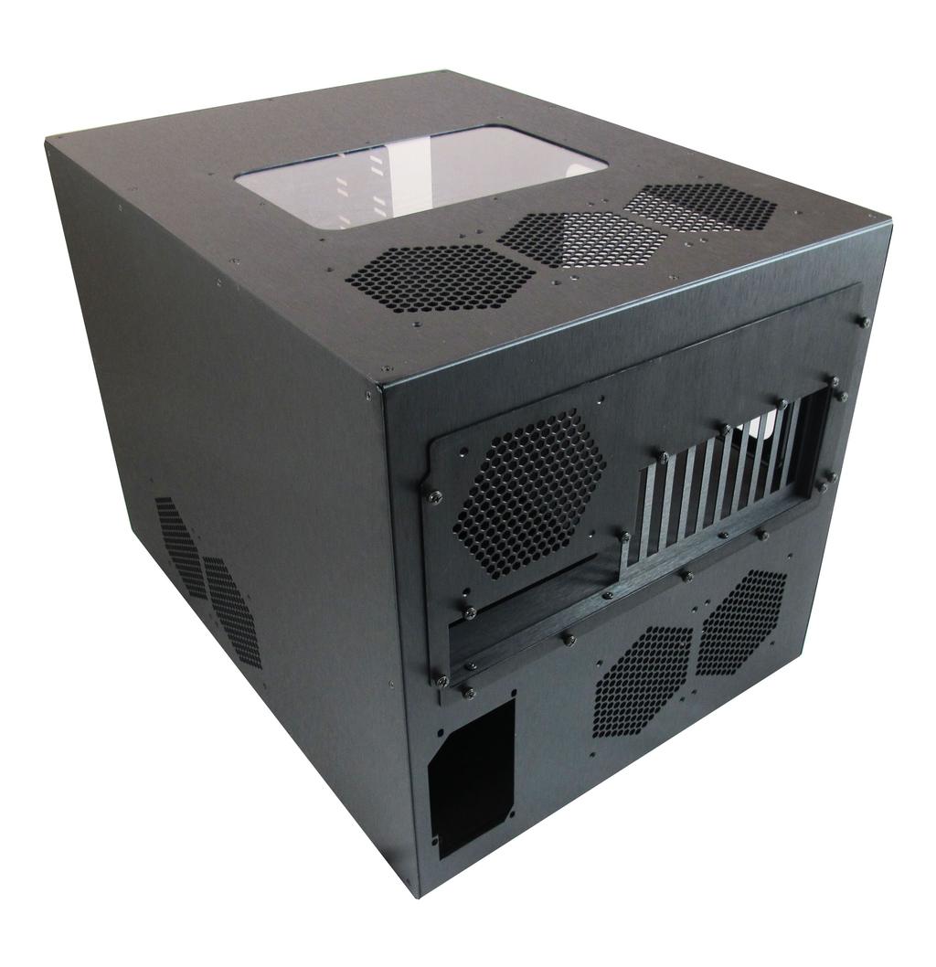
3 Introduction The XSPC H case is a PC case specifically designed for high end PC watercooling. It has support for up to three triple 0mm radiators, two dual 0mm radiators, and leaves plenty of space for tubing routing. The case is supplied in flat pack form, so you will need a little time and patience to get it setup correctly. Assembly should take - hours, depending on your experience level. This manual gives step by step instructions for assembling the H case. It is advisable to read all the way through the instructions at least once before you start assembly. It will save time in the long run. When you are ready to begin installation, you should first unpack the box and check that no components are missing (see pages -6). If any parts are missing from the box please contact XSPC technical support. Specification Dimensions: 69. x x 59.8mm Material: Brushed aluminium Black anodized Screw size: 6- UNC Features: 8x 5.5 bays * 5x HDD bays (0x with optional extra HDD cage.) x SSD tray (up to 0x with optional extra trays) 6x 0mm fan grills - x Triple 0mm - x Dual 0mm - x Single 0mm x Acrylic windows *Front 5.5 bay covers sold separately Page


![Panel x [C]](/docs-images/89/99964531/images/4-2.jpg "Front Panel")
![x [D] Top](/docs-images/89/99964531/images/4-3.jpg "Panel x [E]")

4 Component List [A] Base Panel x [B] Back Panel x [C] Front Panel x [D] Top Panel x [E] Right Panel x [F] Left Panel x Page
![[G] MB](/docs-images/89/99964531/images/5-0.jpg "Cover Panel")
![x [H] PCI](/docs-images/89/99964531/images/5-1.jpg "Panel x [I]")


5 [G] MB Cover Panel x [H] PCI Panel x [I] Motherboard Tray x [J] HDD Rack x [K] 5.5 Bay Cage x [L] L Beam x Page 4


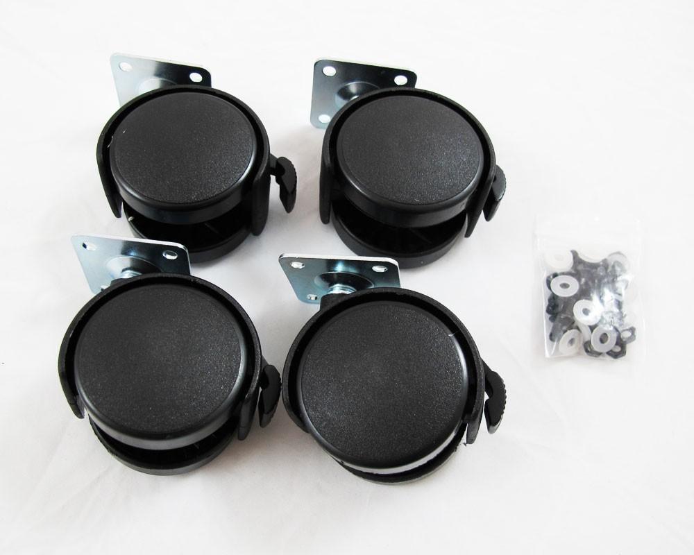
6 Accessories SSD Tray x Castors x4 PCI Slot Covers x0 Neoprene Pad x Power Switch x Support Post x Page 5


7 6- Thumb Screw x8 6- Countersink Screw x 6- Hex Screw x5 Motherboard Standoff x Optional Accessories / Spares Optional accessories and spares can be purchased from or from an approved XSPC reseller Page 6


8 Part : Preparing the Base Panel Take panel [A] and place it on a flat surface, protected by a clean sheet. On the underside of the panel attach a washer and nut to each screw and tighten using a screwdriver. 5 Place the HDD cage over the screw holes shown above. Place a castor under a corner of the panel and line up the 4 holes. Put a screw through each hole. 4 Repeat the process for each of the four castors. 6 Use four 6- thumb screws to attach the HDD cage to the panel. Page 7


![Part : Preparing the Back Panel Put panel [B] on a flat](/docs-images/89/99964531/images/9-4.jpg "surface facing upward.")
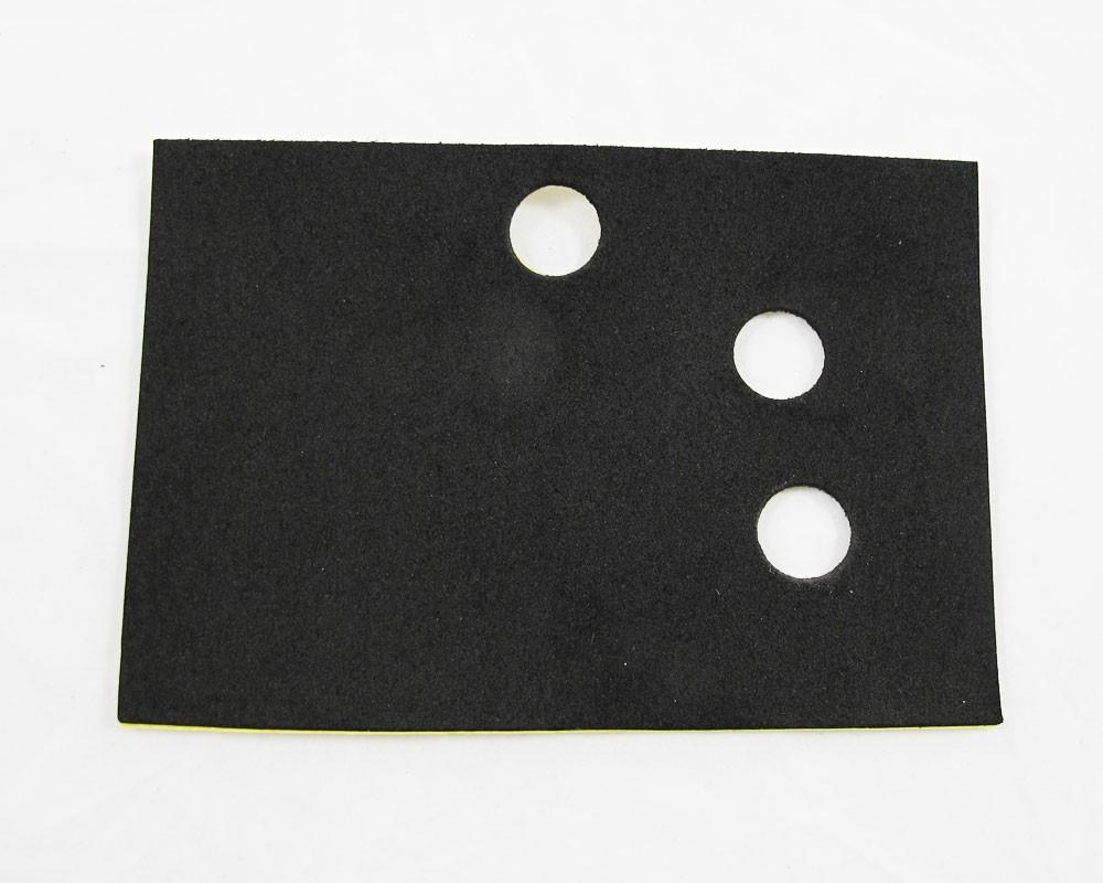
9 7 8 Before you continue, make sure your case matches the photo above. Remove the tape from the neoprene pad and stick it to the HDD cage. Make sure the holes line up. Part : Preparing the Back Panel Put panel [B] on a flat surface facing upward. Place panel [G] over panel [B] and line up the four holes. Attach panel [G] using four 6- thumb screws. Page 8
10 Part : Preparing the Front Panel Place panel [C] facing down on a flat surface. You will need to use a small screwdriver due to limited space. 5 Flip the panel over and thread the power cables through the hole on the front. Take one of the [K] bay cages and attach it using 6 countersunk screws. 4 Repeat steps and for the other side. 6 On the reverse side place an oring and nut over the switch then tighten the nut. Page 9


![Take one of the [K] bay cage and](/docs-images/89/99964531/images/11-4.jpg "attach it using 6 countersunk")

11 Part : Preparing the Front Panel Place panel [C] facing down on a flat surface. You will need to use a small screwdriver due to limited space. 5 Flip the panel over and thread the power cables through the hole on the front. Take one of the [K] bay cage and attach it using 6 countersunk screws. 4 Repeat steps and for the other side. 6 On the reverse side place an oring and nut over the switch then tighten the nut. Page 9

![[B] and slot the corners together.](/docs-images/89/99964531/images/12-1.jpg "Make sure the HDD cage is near the")


12 Part 4: Attaching the Back Panel Take the prepared panels [A] and [B] and slot the corners together. Make sure the HDD cage is near the back. Repeat this for the two screw holes on the other side. Use two countersunk screws in the two holes highlighted above. 4 On the underside of the case use two 6- countersunk screws in the locations above. Page 0

![[C] and slot the corners together.](/docs-images/89/99964531/images/13-1.jpg "Repeat this for the two screw holes on")


13 Part 5: Attaching the Front Panel Take the prepared panel [A] and front panel [C] and slot the corners together. Repeat this for the two screw holes on the other side. Use two countersunk screws in the two holes highlighted above. 4 On the underside of the case use two 6- countersunk screws in the locations above. Page


14 Part 6: Fitting the L Beams Take an L beam and slot it into the corners of the front and back panels. Use two countersunk screws to attach the L beam to the front and back panels. Line up the screw holes on each side of the L beam. 4 Repeat this for the other side, using the second L beam. Page

![[I] next to each other.](/docs-images/89/99964531/images/15-1.jpg "Use three 6- hex screws to attach [I]")
![and [H].](/docs-images/89/99964531/images/15-2.jpg "5 Line up the eleven holes on the back")

![Move panel [H] over panel [I] and line](/docs-images/89/99964531/images/15-4.jpg "up the screwholes.")

15 Part 7: Preparing and Fitting the Motherboard Tray Place panels [H] and [I] next to each other. Use three 6- hex screws to attach [I] and [H]. 5 Line up the eleven holes on the back and use 6- thumb screws to attach the motherboard tray. Move panel [H] over panel [I] and line up the screwholes. 4 From the inside of the case place the motherboard tray over the HDD cage. 6 Place the support post between the case and motherboard and use 6- screws to secure it. Page


![panel [D] on top of the case and attach](/docs-images/89/99964531/images/16-3.jpg "it using ten countersunk screws.")
16 Part 8: Fitting the Top and Side Panels When fitting the side panels you should loosely fit each screw before tightening. This will allow you to shift the panel into line. Repeat this for the right panel [E] Place panel [D] on top of the case and attach it using ten countersunk screws. 4 Repeat this for the left panel [F] Page 4


 6- countersunk screws to attach the radiator to the case panel.")
17 Radiator placements The H supports up to three triple and two dual 0mm radiators. XSPC radiators can be mounted on the front, back, top or side panels using the provided 6- screws. You can alternatively use a triple 40mm radiator by using an optional XSPC 40mm bracket set. The left side of the base panel of the case has pre-drilled holes for the 40mm brackets. The radiator installation process below shows an RS60 radiator being mounted on the front panel. The installation process is the same for each of the five radiator positions. Pick the most suitable radiator placement for your setup.. Use short (under 6mm) 6- countersunk screws to attach the radiator to the case panel. Place the radiator in the required position and line up the holes. 4 Repeat this process for all screw holes on the radiator. Page 5
18 Troubleshooting Q The side panel screw holes don't line up A Loosen all the screws on the side panel and slide the panel until the holes line up. You should only tighten the side panel screws when all screws are in place. Q I was not supplied with any 5.5 bay covers A This is normal. 5.5 bay covers are sold separately. Q - Motherboard tray does not fit A Make sure you have not connected panel [H] to panel [G] before fitting the motherboard tray. Q - Power switch doesn't light up A - It's likely that the power led is connected the wrong way on the motherboard header. Q - Power switch not working A Make sure you have connected the switch to the correct header on the motherboard. Q I am missing a part or I have lost a part A Please contact XSPC support for assistance XSPC Contact Details Website - Support - Copyright XSPC (UK) Limited 0 XSPC is a registered trademark of XSPC (UK) Limited Page 6
19
XSpc. Contents. Page 3-5. Component list. Preparing the back panel
 H Tower Contents Component list Page 3-5 Accessories Page 5-6 Preparing the base panel Page 7 Preparing the back panel Page 8 Preparing the front panel Page 9 Attaching the back panel Page 0 Attaching
CNC Router Parts PRO Machine Kit Cable Track Installation Instructions
 1 1 X CABLE TRACK TRAYS & BRACKETS The cable track on the side of the system is supported by a metal tray (or multiple trays for longer systems such as a PRO4896). These trays hang from brackets on the
Instructions for G5 backplate replacement and motherboard mounting.
 Instructions for G5 backplate replacement and motherboard mounting. Kit contents: 1 x Motherboard tray; 8 x 8mm M3 Standoffs and washers; 4 x M3.5 short cross head screws (attach mobo tray to up to 4 lower
Bone Box. Created by Phillip Burgess. Last updated on :31:04 PM UTC
 Bone Box Created by Phillip Burgess Last updated on 2018-08-22 03:31:04 PM UTC Guide Contents Guide Contents Preparation Parts List Before assembly Assembly 1: Attach BeagleBone to Base Plate 2: Assemble
43107 Rhino Jerry Can Holder Rhino Jerry Can Holder - Horizontal
 Important: Please read these instructions carefully prior to installation. Check the contents of kit before commencing fitment and report any discrepancies. Clean the alloy tray prior to installation.
3400 to 3440 Scarfing Sled Owners Manual Please Read Carefully!
 3400 to 3440 Scarfing Sled Owners Manual Please Read Carefully! Parts List: Please identify and verify that you have all of the hardware shown. Please refer to photos in the instructions for the parts
Installing the Profile Privacy Panel. Assemble top mounting bracket. Prerequisites. Tools
 Installing the Profile Privacy Panel Complete these instructions to install the Profile Privacy Panel. Privacy panels are available in various heights to match tiers and include mounting hardware for slat
F l a t S c r e e n A R M S I n s t a l l a t i o n
 ITEM NUMBERS (1) #TOACAORG16 (2) #TOACAORG20 (3) #TOACATRP24 (4) #TOACATRP30 (5) #TOACATRPDS (6) #TOACATRPSS TOOLS REQUIRED (1) 3/8 Wrench (not provided) (2) Phillips head screwdriver (not provided) (1)
INSTALL LOAD BED TRACKS
 Universal LOAD BED TRAY & Load BArs TRBU001 / KRLBUNI1 INSTALL TIME: 2.5 Hours READ ME FIRST: Thank you for purchasing a Front Runner Slimline II Load Bed Rack or Load Bar Kit. Your Kit will contain the
Mountain Mods Modular Removable Motherboard Tray Instructions / Assembly
 Mountain Mods Modular Removable Motherboard Tray Instructions / Assembly The Mountain Mod Modular/Removable motherboard tray comes flat packed. Each individual item is wrapped tightly in a special non-adhesive
Copyright Black Box Corporation. All rights reserved Park Drive Lawrence, PA Fax
 Copyright 2003. Black Box Corporation. All rights reserved. 1000 Park Drive Lawrence, PA 15055-1018 724-746-5500 Fax 724-746-0746 JULY 2003 RM3010A RM315-R2 RM323-R2 RM329 RM451 RM457 RM3020A RM316 RM324-R2
BOB SLAY (assembly instructions)
") BOB SLAY (assembly instructions) Items included: 7 x Acrylic cutouts labeled A-G 1 x Acrylic IO Panel 1 x Acrylic locking plate of PCI cards 2 x Acrylic 5.25 spacers 2 x momentary switches (power/reset)
BOB SLAY (assembly instructions) Items included: 7 x Acrylic cutouts labeled A-G 1 x Acrylic IO Panel 1 x Acrylic locking plate of PCI cards 2 x Acrylic 5.25 spacers 2 x momentary switches (power/reset)
For additional assistance call
 The following pages will help guide you through the process of assembling your new 48 custom prize wheel. Choose an assembly area with plenty of room to lay your pieces on the floor and also a bench or
INSTALLATION INSTRUCTIONS DODGE RAM 2 & 4WD 1500 PART # P5058
 INSTALLATION INSTRUCTIONS 2009-13 DODGE RAM 2 & 4WD 1500 PART # P5058 PARTS LIST: Qty Description Qty Description 1 Grille Guard 12 12-1.75mm Hex Nuts 2 Upper Frame Mounting s (for trucks without tow hooks
6000 Horizontal Router Table Owners Manual Please Read Carefully!
 6 Horizontal Router Table Owners Manual Please Read Carefully! Parts List Please identify and verify that you have all of the hardware & parts shown prior to assembly. The parts described in this box are
Cable Tray Kit: - Cable Tray - Cable Tray Cover - Power Block Support (x2) Top Support Kit: (x2) - 2 Top Supports. Quantities are per bench
 Top Support Kit: (x2) - 2 Top Supports. Quantities are per bench") Parts Included (per back to back bench) Column Kit: (x2) - 1 LH & 1 RH Column - Control Box - Hand Switch Cable Tray Kit: - Cable Tray - Cable Tray Cover - Power Block Support (x2) Depth Support Kit: -
Parts Included (per back to back bench) Column Kit: (x2) - 1 LH & 1 RH Column - Control Box - Hand Switch Cable Tray Kit: - Cable Tray - Cable Tray Cover - Power Block Support (x2) Depth Support Kit: -
FitWork Walkstation Series 7 AdjusTables
 FitWork Walkstation Tools Required: #2 Phillips Bit with Extension Page 1 of 20 A7TG660606H A7TR663232H FitWork Walkstation 4mm Hex Head Bit A7TG660632H A7TR383030H www.details-worktools.com A7TG663206H
ASSEMBLY AND ADJUSTMENT
 EPPA MONITOR ARM EPPA Rev A 10/17 Model EPPA-XXX ASSEMBLY AND ADJUSTMENT EPPA MONITOR ARM PARTS AND TOOLS PLEASE REVIEW these instructions before beginning the assembly and adjustment procedures. Check
Desk/Wall-Mount Rack
 Desk/Wall-Mount Rack Patent(s) Pending Installation Instructions Post P/N: 119-1752 119-1781 119-1782 119-4014 Frame P/N: 119-1591 119-1754 119-1755 Kit Contents (2) Frames (4) Posts Assembly Hardware
PRS X-Axis E-Chain Installation For Tools with a 12 Z-Axis
 888-680-4466 ShopBotTools.com PRS X-Axis E-Chain Installation For Tools with a 12 Z-Axis This kit is compatible with PRS Shopbots that have an X-axis cutting area of 96 to 144. It is not immediately compatible
A500 ASSEMBLY & INSTALLATION INSTRUCTIONS
 ASSEMBLY & INSTALLATION INSTRUCTIONS 1 CONTENTS 2 Component Parts A B Canopy Mounting Plate C Cap (3) D Threaded Nipple E Threaded Standoffs (2) F Anchors (8) G #10 Screws (8) H Safety Cable (2) I Safety
ASSEMBLY INSTRUCTIONS FOR SL500A AND SL500AL
 ASSEMBLY INSTRUCTIONS FOR SL500A AND SL500AL January 2013 The SL500A is a square upright glass cabinet with a single hinged lockable door. It has five adjustable shelves plus the base. It also has an optional
788XL Dado Jig Owners Manual Please Read Carefully!
 788XL Dado Jig Owners Manual Please Read Carefully! 788XL Dado Jig Hardware List: Identify and verify that you have all of the hardware shown below prior to assembly. Tools needed for assembly: #2 & 3
INSTALLATION INSTRUCTIONS 3000 SERIES STEP GUARD (CENTER GRILLE GUARD & BRUSH GUARDS) CHEVROLET SILVERADO 2500 & /4WD PART # 3168 (MB-MC)
 CHEVROLET SILVERADO 2500 & /4WD PART # 3168 (MB-MC)") INSTALLATION INSTRUCTIONS 3000 SERIES STEP GUARD (CENTER GRILLE GUARD & BRUSH GUARDS) CHEVROLET SILVERADO 2500 & 3500 2/4WD PART # 3168 (MB-MC) PACKING LIST 2 ¼ X ¾ BUTTON HEAD BOLTS 8 5/16 X 3/4 BUTTON
INSTALLATION INSTRUCTIONS 3000 SERIES STEP GUARD (CENTER GRILLE GUARD & BRUSH GUARDS) CHEVROLET SILVERADO 2500 & 3500 2/4WD PART # 3168 (MB-MC) PACKING LIST 2 ¼ X ¾ BUTTON HEAD BOLTS 8 5/16 X 3/4 BUTTON
TITAN2-EDGE Public Access Computer Station Dual Track
 TITAN2-EDGE Public Access Computer Station Dual Track TITAN2-EDGE Rev A 6/17 Model TITAN2-EDGE ASSEMBLY AND ADJUSTMENT TITAN2-EDGE PARTS AND TOOLS PLEASE REVIEW these instructions before beginning the
INSTALLATION INSTRUCTIONS
 INSTALLATION INSTRUCTIONS SPORTSMAN WINCH MOUNT GRILLE GUARD APPLICATION: 2016-2018 Toyota Tacoma PART NUMBER: 40-93885, 45-93880, 46-23885 ITEM QUANTITY DESCRIPTION TOOLS NEEDED 1 1 WINCH TRAY 15MM SOCKET
JEEP JK ( 5 DOOR ) SLIMLINE II - FULL TRAY EXTREME RACK KIT
 SLIMLINE II - FULL TRAY EXTREME RACK KIT") JEEP JK ( 5 DOOR ) SLIMLINE II - FULL TRAY EXTREME RACK KIT FAJK001 / KRJW014T INSTALL TIME: 2.5 Hours NOTE: Your Jeep JK (5 Door) Extreme Roof Rack Kit consists of four boxes. (1) the Tray, (2) the Roll
JEEP JK ( 5 DOOR ) SLIMLINE II - FULL TRAY EXTREME RACK KIT FAJK001 / KRJW014T INSTALL TIME: 2.5 Hours NOTE: Your Jeep JK (5 Door) Extreme Roof Rack Kit consists of four boxes. (1) the Tray, (2) the Roll
Installing The Aliens Extermination Deluxe 50" Cabinet with Sintra Marquee
 Installing The Aliens Extermination Deluxe 50" Cabinet with Sintra Marquee Document Part #: 040-0262-01 This document describes how to install The Aliens Extermination Deluxe Cabinet with Sintra Marquee
INSTALLATION INSTRUCTIONS GRILLE GUARD RAM 1500 PART # 5058/5058-2
 INSTALLATION INSTRUCTIONS GRILLE GUARD PART # 5058/5058-2 PARTS LIST: Qty Description Qty Description 1 Grille Guard 8 12-1.75mm x 35mm Hex Bolts 2 Upper Frame Mounting s (for trucks without tow hooks
Codonics SLS 500i Shelf Installation
 Codonics SLS 500i Shelf Installation Blue Bell Cart or Generic Blind Mounting Technical Brief Overview This document explains how to properly install the Codonics Safe Label System SLS 500i shelf with
WAREHOUSE HANGER INSTALLATION INSTRUCTIONS R H INS T A L L A TIO N INS T R U C TIO N S
 INS T A L L A TIO N INS T R U C TIO N S WAREHOUSE HANGER NOTE: Due to the size and weight of the Warehouse Hanger it is recommended that this Hanger be installed on 3 4 or wider doors. 10.11.2016 2-3/16"
Copyright Black Box Corporation. All rights reserved Park Drive Lawrence, PA Fax
 Copyright 2004. Black Box Corporation. All rights reserved. 1000 Park Drive Lawrence, PA 15055-1018 724-746-5500 Fax 724-746-0746 JANUARY 2004 RF500A RF507A RF514A RF521A RF501A RF508A RF515A RF522A RF502A
OWNER S MANUAL CONTENTS. The only table saw fence with Automatic Positioning Control TM
 The only table saw fence with Automatic Positioning Control TM OWNER S MANUAL Please read this owner s manual before use and keep it at hand for reference. Note: The INCRA TS III system consists of three
Race Splitter Upgrade Kit Installation Instructions
 Race Splitter Upgrade Kit Installation Instructions Eric Hazen Rev. 1 Overview: Detailed instructions on installing the FT86 Speed Factory Race Splitter Upgrade Kit on a BRZ; FR-S grills are different
7902 Dado Jig. Owners Manual Please Read Carefully! Hardware List: 7902 Parts List:
 7902 Dado Jig Owners Manual Please Read Carefully! 7902 Dado Jig Hardware List: Identify and verify that you have all of the hardware shown below prior to assembly. Please read the instructions at least
DRAWER Mitsubishi pajero lwb
 DRAWER Mitsubishi pajero lwb SSDS601 / SSMP001 INSTALL TIME: 45 mins Thank you for purchasing a Front Runner Storage System. This Storage System is made up of the following components: 1. A Drawer System
Show us what you have! R40 OWNERS MANUAL BECOME LEGEND SHOOT YOUR FINISHED R40 SUBMIT YOUR PHOTOS
 Show us what you have! the hex gear hall of fame is reserved for only the finest examples of quality built systems. Think you deserve a place among the ranks? SHOOT YOUR FINISHED R40 BUILDS@HEX-GEAR.COM
Queen Wingback Bed King Wingback Bed
 Parts and Hardware List A. Side Rails with Attachment Hooks 2 pcs B. Foot Rail 1 pc C. Head Rail 1 pc D. Center Support Slat 1 pc E. Leg Supports 3 pcs F. Support Slats 4 pcs G. Flat Washers 8 pcs H. Lock
LP-200 Dummy Load / Wattmeter
 LP-200 Dummy Load / Wattmeter Enclosure Retrofit Assembly Instructions March 2009 TelePost Incorporated LP-200 is a trademark of TelePost Inc. Material in this document copyrighted 2009 TelePost Inc. 1
AUDIOARTS A - LINE f u r n i t u r e ASSEMBLY INSTRUCTIONS July 2005
 A-L A UDIOARTS A-LINE furniture ASSEMBLY INSTRUCTIONS July 2005 A-Line Furniture Assembly Instructions - 1st Edition 2005 Audioarts Engineering* AUDIOARTS ENGINEERING 600 Industrial Drive New Bern, North
EPPA2-KIT DUAL MONITOR ARM CONVERSION
 EPPA2-KIT DUAL MONITOR ARM CONVERSION EPPA2-KIT Rev A 10/17 Model EPPA2-KIT-XXX ASSEMBLY AND ADJUSTMENT EPPA2-KIT PARTS AND TOOLS PLEASE REVIEW these instructions before beginning the assembly and adjustment
Bunk Pod Front Entry Assembly Instructions
 Bunk Pod Front Entry Assembly Instructions www.podtime.co.uk enquiries@podtime.co.uk Working House Ltd How to assemble your pod This step by step guide will show how to assemble your pod(s) on site. It
JEEP JK ( 5 DOOR ) SLIMLINE II - FULL TRAY EXTREME RACK KIT
 SLIMLINE II - FULL TRAY EXTREME RACK KIT") JEEP JK ( 5 DOOR ) SLIMLINE II - FULL TRAY EXTREME RACK KIT FAJK002 / KRJW014T INSTALL TIME: 5 Hours NOTE: Your Jeep JK (5 Door) Extreme Roof Rack Kit consists of four boxes. (1) the Tray, (2) the Roll
JEEP JK ( 5 DOOR ) SLIMLINE II - FULL TRAY EXTREME RACK KIT FAJK002 / KRJW014T INSTALL TIME: 5 Hours NOTE: Your Jeep JK (5 Door) Extreme Roof Rack Kit consists of four boxes. (1) the Tray, (2) the Roll
790XL Dado Jig Owners Manual Please Read Carefully!
 790XL Dado Jig Owners Manual Please Read Carefully! 790XL Dado Jig Hardware List: Identify and verify that you have all of the hardware shown below prior to assembly. Tools needed for assembly: #2 & 3
PRS Retro Z-Axis Installation
 PRS Retro Z-Axis Installation Page -1- PRS Retro Z-Axis Installation This document is a guide to installing the PRS Retro Z-axis on early ShopBot models. It describes installation for PR models with PK299
CAB END BEDTRAX (SIDE VIEW)
") Supplied Hardware: (8-14) 1/4-20 Allen head bolts, (12-18) UHMW mount blocks, (4) D-ring tie downs Tools Needed: Allen head wrench GET TO IT. INSTALLATION INSTRUCTIONS STEP 1. INSERT (2) MOUNT BLOCKS INTO
Supplied Hardware: (8-14) 1/4-20 Allen head bolts, (12-18) UHMW mount blocks, (4) D-ring tie downs Tools Needed: Allen head wrench GET TO IT. INSTALLATION INSTRUCTIONS STEP 1. INSERT (2) MOUNT BLOCKS INTO
Wooden Frame Type Instruction Manual
 Wooden Frame TypeInstruction Manual Thank you for selecting our product. Before starting installation, please read this manual thoroughly to ensure correct installation. Please keep this manual at hand
Installing the CACS Ceiling with Aisle Ducts
 Installing the CACS Ceiling with Aisle Ducts Complete these instructions to install the Cold Aisle Containment System (CACS) Ceiling with Aisle Ducts. The CACS Ceiling and Aisle Ducts are designed to work
Therma-Tru Door Gallery Setup Instructions Swing Unit with Hardware Kit - Hardware Part # MADGSWU15 (Swing Unit) Part # MADGHKSU10 (Hardware Kit)
 Part # MADGHKSU10 (Hardware Kit)") Swing Unit with Hardware Kit - Hardware Tools Included: 4mm Allen Wrench, 6mm Allen Wrench, 8mm T-Handle Allen Wrench (1) 3/4" Drill Bit, (1) 7/32" Drill Bit and Hole Template Guide Tools Required: Phillips
Swing Unit with Hardware Kit - Hardware Tools Included: 4mm Allen Wrench, 6mm Allen Wrench, 8mm T-Handle Allen Wrench (1) 3/4" Drill Bit, (1) 7/32" Drill Bit and Hole Template Guide Tools Required: Phillips
EmagiKit. Privacy Pod Plus. Quiet. Easy. Affordable. INSTRUCTIONS ASSEMBLY
 EmagiKit Privacy Pod Plus Quiet. Easy. Affordable. INSTRUCTIONS ASSEMBLY DIMENSIONS AND COMPONENTS 47 47 Ceiling Unit 2-B 2-L 2-R Glass Door Corner Trim Door Handle 90 Adjustable Height Work Surface 1-B
Privacy Wall Glass Selections - Polished Edge Slider Door
 Privacy Wall Glass Selections - Polished Edge Slider Door 3/6" HEX BIT PUTTY KNIFE #2 ACR BIT SUCTION CUP HOLDERS DOOR LEAF: Satin Tempered Clear Tempered LOCTITE 425 SIDE LIGHT ETCHED GLASS STYLES: Satin
Heavy Duty I-Beam Trolley
 Heavy Duty I-Beam Trolley ASSEMBLY INSTRUCTIONS I-BEAM TROLLEY Recommended Tools Level Tape Measure Pencil Drill with 1/8, 1/4, and 3/8, Drill Bits and Phillips Bit Socket Wrench with 9/16 Socket I-BEAM
Page 1 of 5 Instructions for Fitting Lower Grille to S Type Jaguar. Part Code 9048
 Page 1 of 5 Instructions for Fitting Lower Grille to S Type Jaguar. Part Code 9048 To fit this grille you will need: Torch, 10mm spanner, 10mm socket with extension, T30 torx bits, Screwdrivers, Pliers,
Side Winder R o u t e r L i f t.
 Woodpeckers PRECISION WOODWORKING TOOLS Side Winder R o u t e r L i f t. INSTALLATION INSTRUCTIONS The wrench handle must be pointing left in order to fully insert or remove it. Lift Wrench Once fully
The Useless Machine. Parts Only - Build Guide v0001
 TM The Useless Machine Parts Only - Build Guide v0001 For the best outcome, follow each step in order. We recommend reading this guide entirely before you get started. Tools required: One phillips screwdriver,
LOCKN LOAD FIRST TIME INSTALLATION
 LOCKN LOAD TM TRACK MOUNTING KIT NISSAN NAVARA D40 2004-2015 2 BAR TRACK HEAVY DUTY ROOF RACK SYSTEM MAX VEHICLE ROOF LOAD RATING: 100KG TOTAL LOAD EQUALS WEIGHT OF ROOF RACKS + ACCESSORIES + CARGO FIRST
Installation Instructions Kit, Base Rail Bracket Part # 31413
 Installation Instructions Kit, Base Rail Bracket Part # 31413 Dealer / Installer: Provide a copy of these Instructions to the end user of this product. These Instructions provide important operating and
"The Stick" Assembly Instructions
 Back to Main Page "The Stick" Assembly Instructions In Japanese (pdf): right click and save target as. Introduction: Hello and thank you for buying a Stick chassis from TCS. We appreciate your business
KWIK-KIT KK-S INSTALLATION INSTRUCTION PACKAGE
 KWIK-KIT KK-S-120-02 INSTALLATION INSTRUCTION PACKAGE INSTALLATION INSTRUCTIONS HAVIS KWIK-KIT KK-S-120-02 2002-2007 DODGE/FREIGHTLINER SPRINTER VAN PLEASE READ COMPLETE INSTRUCTIONS PRIOR TO INSTALLATION
v1.0 ASSEMBLY GUIDE Mia Wide Bookcase
 v1.0 ASSEMBLY GUIDE Mia Wide Bookcase Components Upon unpacking your bookcase from it s delivery box, you should have the pieces shown. Follow the steps on the next pages to assemble your new bookcase.
INSTALLATION INSTRUCTIONS INS T A L L A TIO N INS T R U C TIO N S ROD IRON SCROLL HANGER R H
 INS T A L L A TIO N INS T R U C TIO N S ROD IRON SCROLL HANGER 10.5.2016 2-1- 3/16" 11/16" 8" 8 O 2-7/8 Ø2-7/8" 3-1/2 3-1/2" 12-9/16 12-9/16" PLEASE NOTE: These instructions are specific to a particular
ContainAire Dual Sliding Door Unit Pictogram User Installation Guide
 ContainAire Dual Sliding Door Unit Pictogram User Installation Guide 2014 Tate Access Floors, Inc. 1 Introduction Thank you for choosing a Tate Airflow product. Tate Airflow products are engineered to
INS T A L L A TIO N INS T R U C TIO N S HORSESHOE W/ BAR HANGER
 INS T A L L A TIO N INS T R U C TIO N S HORSESHOE W/ BAR HANGER 6-1/2" 5" 2-7/16" 3-7/16" Ø2-7/8" 4-7/8" 11" 2" 3/16" 1/2" HORSESHOE W/ BAR S P ECIFICATIONS PARTS AND TOOLS Tools Needed Tape Measure Pencil
Constable Oak Extension Dining Table
 Constable Oak Extension Dining Table Assembly Instructions - Please keep for future reference 176/0325 Dimensions Width - 160/ 200cm Depth - 90cm Height - 75cm Important - Please read these instructions
S6 User s Manual USER S MANUAL ver. 1.0
 S6 User s Manual SKEETER - 1U LOW PROFILE SOLUTION Table of Contents Tabletop Configuration 2 Tabletop Configuration Accessories 4 Slide Configuration 5 slide configuration accessories 7 rack Mount configuration
REC Series Rack Installation Guide
 REC Series Rack Installation Guide 1 REC Series Rack Installation Guide TABLE OF CONTENTS SECTION SAFETY WARNINGS 1 600 WIDE EXPLODED VIEW 2 800 WIDE EXPLODED VIEW 3 SWITCHING DOOR HANDING 4 STABILIZING
INSTALLATION INSTRUCTIONS HEAVY DUTY TILT WALL MOUNT Model: PPH-2000
 INSTALLATION INSTRUCTIONS HEAVY DUTY TILT WALL MOUNT Model: PPH-2000 Specifications: Accomodates Akira and Orion 84" displays without interface bracket; accomodates other large flat panel displays with
Installation Manual. SKU# TracVan Double SKU# TracVan Double SKU# TracVan Triple
 Installation Manual SKU# 29054 TracVan Double SKU# 29055 TracVan Double SKU# 29056 TracVan Triple TRACVAN INSTALLATION INSTRUCTIONS SKU# 29054, 29055 & 29056 TracVan installation is straightforward, and
HARDWARE KIT # KKM or Rear Compartment: (Some hardware not used in all applications)
") PRISONER TRANSPORT INSTRUCTIONS for CHEVROLET EXPRESS VAN PT-C01-100-2A TOOLS REQUIRED: Standard and Metric Socket Sets Awe or Scribe Tape Measure Impact Gun (recommended) Pry-bar Caulk gun Drill & drill
PRISONER TRANSPORT INSTRUCTIONS for CHEVROLET EXPRESS VAN PT-C01-100-2A TOOLS REQUIRED: Standard and Metric Socket Sets Awe or Scribe Tape Measure Impact Gun (recommended) Pry-bar Caulk gun Drill & drill
ASSEMBLY GUIDE. Mia Narrow Bookcase
 ASSEMBLY GUIDE Mia Narrow Bookcase Components: Upon unpacking your bookcase from it s delivery box, you should have the pieces shown. Follow the steps on the next pages to assemble your new bookcase. Step
INSTALLATION INSTRUCTIONS GRILLE GUARD 09-ON DODGE RAM PART #
 INSTALLATION INSTRUCTIONS GRILLE GUARD 09-ON DODGE RAM PART # PARTS LIST: Qty Description Qty Description 1 Grille Guard 8 12-1.75mm x 35mm Hex Bolts 2 Brackets (for trucks without 22 12mm x 30.1mm OD
STEP 1 STEP 2 LEVELER KIT OPTION MOBILE CASTER KIT OPTION
 B SERIES INDUSTRIAL BENCHES TOOLS REQUIRED FOR ASSEMBLY Socket set, Open end wrench set, Cordless drill with 3/8" socket bit (Magnetic recommended). BEFORE ASSEMBLY Read through the assembly instructions
U.S. Solar Mounts TOP Mount Installation Instructions. Adjustable 4 (2) 60-Cell Module Top-of-Pole Mount REV 1
 60-Cell Module Top-of-Pole Mount REV 1") U.S. Solar Mounts 4260 TOP Mount Installation Instructions Adjustable 4 (2) 60-Cell Module Top-of-Pole Mount REV 1 Ultra-Rugged Solar Mounting Solutions 2017 U.S. Solar Mounts Corp. All Rights Reserved
U.S. Solar Mounts 4260 TOP Mount Installation Instructions Adjustable 4 (2) 60-Cell Module Top-of-Pole Mount REV 1 Ultra-Rugged Solar Mounting Solutions 2017 U.S. Solar Mounts Corp. All Rights Reserved
INSTALLATION INSTRUCTIONS INS T A L L A TIO N INS T R U C TIO N S THE MAVERICK HANGER R H
 INS T A L L A TIO N INS T R U C TIO N S THE MAVERICK HANGER 10.6.2016 PARTS INSTALLATION SPECIFICATIONS AND TOOLS INSTRUCTIONS 2-1/4" 2-7/8 11-3/8" 1/4" 2-1/8 PARTS INSTALLATION AND INSTRUCTIONS TOOLS
4099T Parts List. Front Bow Assy. (1) Rear Bow Assy. (1) Long Mounting Rail (2) Short Mounting Rail (2)
 Rear Bow Assy. (1) Long Mounting Rail (2) Short Mounting Rail (2)") 4099T Parts List Ver.2 Front Bow Assy. (1) Rear Bow Assy. (1) Small Mnt Foot (2) Large Mount Foot (2) Ladder Hook (2) Ladder Stop (2) Handle Extension (1) Long Mounting Rail (2) Short Mounting Rail (2)
4099T Parts List Ver.2 Front Bow Assy. (1) Rear Bow Assy. (1) Small Mnt Foot (2) Large Mount Foot (2) Ladder Hook (2) Ladder Stop (2) Handle Extension (1) Long Mounting Rail (2) Short Mounting Rail (2)
3,500/4,500lb. Vertical Cable Feighner Lift
 3,500/4,500lb. Vertical Cable Feighner Lift CAUTION - PUT SAFETY FIRST 1. Before attempting to install or operate this lift, study and fully understand the proper operating procedures and safety precautions
e997 Articulating Wall Arm MANUAL IM004-03
 e997 Articulating Wall Arm MANUAL 10.18.16 IM004-03 0 WELCOME The Enovate Medical e997 Articulating Wall Arm was designed to set a new standard in quality. Enovate Medical s goal is to provide a wall arm
D2/367A ASSEMBLY INSTRUCTIONS 6 BAY AV CREDENZA. Salamander 6 Bay AV Credenza [5.17] page 1 of 8
![D2/367A ASSEMBLY INSTRUCTIONS 6 BAY AV CREDENZA. Salamander 6 Bay AV Credenza [5.17] page 1 of 8](/thumbs/88/115215636.jpg "D2/367A ASSEMBLY INSTRUCTIONS 6 BAY AV CREDENZA. Salamander 6 Bay AV Credenza [5.17] page 1 of 8") D2/367 SSEMBLY INSTRUCTIONS 6 BY V CREDENZ Salamander 6 Bay V Credenza 503-232 [5.17] page 1 of 8 hardware B I L C J D K M E ID PRT # DESCRIPTION F G H 303-453 1/4-20 x 4 Head Socket Screw B 300-518 1/4-20
D2/367 SSEMBLY INSTRUCTIONS 6 BY V CREDENZ Salamander 6 Bay V Credenza 503-232 [5.17] page 1 of 8 hardware B I L C J D K M E ID PRT # DESCRIPTION F G H 303-453 1/4-20 x 4 Head Socket Screw B 300-518 1/4-20
The brackets have been tested on the 2017 and 2018 versions of the Spirit Proton pack and also with two separate A.L.I.C.E.
 Introduction Congratulations on purchasing the Spirit Brackets Kit that allows very secure attachment of an A.L.I.C.E. pack frame to your Spirit Halloween Proton Pack. The Spirit Brackets Kit is designed
American Morse Equipment
 American Morse Equipment Thank you for purchasing an American Morse Porta Paddle-II Kit. We redesigned the original Porta Paddle for ease of assembly & provide all parts finished and ready for assembly,
Assembly guide. Before you start...check the pack and make sure all the components and fixings are included see. Tools required (Not Supplied)
") M FITT-054 Issue - Issue Assembly guide Soft close 800 LH Pull & Swing Corner Unit Component parts Tools required (Not Supplied) B S O T Spirit level Cross Head Screwdriver Tape measure E&F J P* Allen
M FITT-054 Issue - Issue Assembly guide Soft close 800 LH Pull & Swing Corner Unit Component parts Tools required (Not Supplied) B S O T Spirit level Cross Head Screwdriver Tape measure E&F J P* Allen
SENC 150. Cross Feed Installation... Mounting Information... Center reading head... First Steps...
 Cross Feed Y Axis on Right Hand Side Cross Feed Installation... * Supplied with encoder hardware M4 x 8mm SHSS Mounting block 1/4-20 x 1/2 SHSS (2) per block *1/4-20 x 1 BHCS (2) or 1/4-20 x 1-1/4 BHCS
Sliding Crosscut Table installation guide
 Sliding Crosscut Table installation guide model tsa-sa48 A Note About Color Variations Among Anodized Aluminum Components Congratulations on the purchase of this SawStop Sliding Crosscut Table. We at SawStop
LEANER SETUP MANUAL PATENTED SINGLE AUGER
 LEANER SETUP MANUAL PATENTED SINGLE AUGER GRAIN CARTS (Rev. 06/09/12) J. & M. Mfg. Co., Inc. P.O. Box 547 Ft. Recovery, OH 45846 Ph: (419) 375-2376 Fax: (419) 375-2708 www.jm-inc.com LEANER SETUP MANUAL
Heavy-Duty Bypass Track System
 Heavy-Duty Bypass Track System Please Note: This track system must be installed with the screws going into a solid surface such as studs or a header. Due to the spacing of the holes on these Brackets,
model tsa-sa48 Sliding Crosscut Table installation guide
 model tsa-sa48 Sliding Crosscut Table installation guide A Note About Color Variations Among Anodized Aluminum Components Congratulations on the purchase of this SawStop Sliding Crosscut Table. We at SawStop
Foot Rail. Nissan Navara_Frontier D23 DC START HERE! READ ME FIRST
 Foot Rail Nissan Navara_Frontier D3 DC ENG FANN00 START HERE! READ ME FIRST Don t be a hero and muscle through this without first reading these fitting instructions! Improper installation of this gear
Technical Bulletin #26 Card Reader Installation Issued 3/2/2010
 Technical Bulletin #26 Card Reader Installation Issued 3/2/2010 Card Reader and Price Plate Placement Using the price plate or template provided, use a punch to mark the placement of the holes to be drilled
OWNER S MANUAL CONTENTS. The only table saw fence with Automatic Positioning Control TM
 The only table saw fence with Automatic Positioning Control TM OWNER S MANUAL Please read this owner s manual before use and keep it at hand for reference. Note: The INCRA TS II system consists of three
RE 2 Post Rack System
 Installation Guide RE 2 Post Rack System 1 TABLE OF CONTENTS SAFETY WARNINGS Frame Assembly Guide 4-6 Vertical Cable Manager Assembly Guide 7 + 8 Adjustable Cable Spools 9 + 10 Vertical Cable Basket 11
6 Foot/ 1800mm Aisle Width Net-Contain Aisle Containment for N-Type and S-Type Cabinets
 6 Foot/ 1800mm Aisle Width Net-Contain Aisle Containment for N-Type and S-Type Cabinets Panduit Corp. 2016 INSTALLATION INSTRUCTIONS Page 1 of 36 Component Guide for Doors Dual Sliding Containment Door
Driver/Left Top. Support Bracket
 PARTS LIST: 1 Grille Guard 8 10mm Lock Washers 1 Driver/Left Frame Bracket 8 10mm Hex Nuts 1 Passenger/Right Frame Bracket 2 8-1.25mm x 25mm Button Head Bolts 1 Driver/Left Bottom Support Bracket 2 8mm
Copyright Black Box Corporation. All rights reserved.
 Copyright 2008. Black Box Corporation. All rights reserved. 1000 Park Drive Lawrence, PA 15055-1018 724-746-5500 Fax 724-746-0746 4-Post Steel Open Rack AUGUST 2008 RM7000A RM7001A RM7002 RM7003A RM7004A
OWNER S MANUAL. Safety. Please read this owner s manual before use and keep it at hand for reference. Warranty
 Please read this owner s manual before use and keep it at hand for reference. OWNER S MANUAL Safety Important safety instructions for using the INCRA Miter5000 Before using the INCRA Miter5000, read and
BX1956 Installation Instructions Chrysler PT Cruiser (Include Turbo)
") BX1956 Installation Instructions 2001-04 Chrysler PT Cruiser (Include Turbo) Serial No. The front fascia and metal bumper are removed for baseplate installation. Factory metal bumper will not be reinstalled.
BX1956 Installation Instructions 2001-04 Chrysler PT Cruiser (Include Turbo) Serial No. The front fascia and metal bumper are removed for baseplate installation. Factory metal bumper will not be reinstalled.
LIGHT BEAM ANTENNA MaxRange Antenna Series Assembly Instructions MaxRange Ultra Digital / High Definition Television Antennas
 LIGHT BEAM ANTENNA MaxRange Antenna Series Assembly Instructions MaxRange Ultra Digital / High Definition Television Antennas Assembly Instructions 1 MaxRange Ultra Antenna These instructions will lead
INSTALLATION INSTRUCTIONS SLBU / SLMU UNIVERSAL INTERFACE BRACKETS
 INSTALLATION INSTRUCTIONS SLBU / SLMU UNIVERSAL INTERFACE BRACKETS The Universal Interface Bracket provides a solution for simplifying inventory of RPA and RPM series mounts and SLB/SLM projector brackets.
Assembly Instructions
 Unite Panel System Hinge Door July 2016 #12 x / slotted hex washer head bolt Figure 1 threshold bracket frame Detail F threshold bracket threshold bracket (installed) #12 x / slotted hex washer head bolt
Piazzola Pergola Awning Manufacturing and installation guide
 Piazzola Pergola Awning Manufacturing and installation guide Date Changes Page General information Maximum and minimum width Width Projection 150 to 349 cm 350 to 500 cm From 200 to 250 cm X From 251 to
Factory Assistance: Phone: Fax: Page 1
 CABLE RUNWAY ACCESSORIES Radius Drop / Stringer Drop Provides 3 bend radius Radius drop fits 6, 12 and 18 runway made from 1-1/2 x 3/8 tubing Steel construction Includes (3) cable spools, (1) bolt, (1)