1018V Metal Cutting Band Saw
|
|
|
- Henry West
- 5 years ago
- Views:
Transcription


1 1018V Metal Cutting Band Saw 1018V INSTRUCTION MANUAL - 1 -
2 Table Of Contents Section Page No 1 Machine Overview Safety Machine Specification Transportation of machine Minimum Space For Machine Operation Make proper tooth selection BI-Metal speeds and feeds Starting and stopping machine Adjusting Lower stop Changing speeds and adjusting belt tension Adjusting blade tension Adjusting blade tracking Adjusting blade guide support arm Adjusting feed rate Adjusting cutting pressure of saw arm Operating and adjusting vise Coolant Adjusting stock advance stop Adjusting blade guides and bearings Setting up the machine for operation Removing and installing the blade Hydraulic System Gear box Trouble shooting Circuit Diagram
3 1. Machine Overview WARNING: FAILURE TO FOLLOW THESE RULES MAY RESULT IN SERIOUS PERSONAL INJURY As with all machinery there are certain hazards involved with operation and use of this machine. Proper use of the machine will considerably lessen the possibility of personal injury. If normal safety precautions are overlooked or ignored, personal injury to the operator may result. This machine was designed for specific applications only. We strongly recommend that this machine NOT be modified and/or used for any application other than for which it was designed. If you have any questions relative to applications DO NOT use the machine until you contact the manufacturer and they have advised you. Before using this bandsaw, the proper electrical connections specific to this machine must be followed. Trajan Saw Works accepts no responsibility or liability for damages or injuries caused by improper electrical components and/or connections - 3 -
4 2. SAFETY A) OPERATOR SAFETY: 1. WEAR PROPER APPAREL. Avoid loose fitting clothing, jewelry & gloves 2. ALWAYS WEAR EYE PROTECTION 3. NEVER LEAVE THE SAW RUNNING UNATTENDED. TURN POWER OFF. 4. DO NOT OPERATE THE SAW UNDER THE INFLUENCE OF DRUGS, ALCOHOL, OR ANY PERSCRIPTION MEDICATION 5. ALWAYS KEEP HANDS AWAY FROM THE CUTTING AREA 6. STOP THE SAW BLADE BEFORE CLEANING CHIPS OUT OF THE PAN. 7. KEEP ALL GUARDS IN PLACE & IN WORKING ORDER. C) MACHINE SAFETY: 1. REMOVE ADJUSTING KEYS AND WRENCHES. Form a habit of checking to see that keys and adjusting wrenches are removed from tool before turning it "on". 2. DON'T FORCE THE SAW. It will do the job better and be safer at the rate for which it was designed. 3. PROPER USE OF ATTACHMENTS. Do not use attachment to do a job for which they were not designed. 4. SECURE WORK. Use clamps or the saw vise to hold work. 5. MAINTAIN SAW BLADES IN TOP CONDITION. Keep saw blades sharp & clean for best performance. Follow instructions for lubricating and changing saw blades. 6. AVOID ACCIDENTAL STARTING. Make sure switch is in OFF position before plugging in power cord. 7. ADJUST AND POSITION the blade guide arm before starting the cut. 8. KEEP BLADE GUIDE ARM TIGHT, A loose blade guide arm aill affect sawing accuracy. 9. MAKE SURE blade speed is set correctly for the material being cut. 10. CHECK for proper blade size and type. 11. STOP the machine before putting material in the vise. ALWAYS have stock firmly clamped in vise before starting cut. 12. REMOVE ADJUSTING KEYS AND WRENCHES. Form a habit of checking to see that keys and adjusting wrenches are removed from tool before turning it "on". 13. DON'T FORCE THE SAW. It will do the job better and be safer at the rate for which it was designed. 14. PROPER USE OF ATTACHMENTS. Do not use attachment to do a job for - 4 -
5 which they were not designed. 15. SECURE WORK. Use clamps or the saw vise to hold work. 16. MAINTAIN SAW BLADES IN TOP CONDITION. Keep saw blades sharp & clean for best performance. Follow instructions for lubricating and changing saw blades. 17. AVOID ACCIDENTAL STARTING. Make sure switch is in OFF position before plugging in power cord. 18. ADJUST AND POSITION the blade guide arm before starting the cut. 19. KEEP BLADE GUIDE ARM TIGHT, A loose blade guide arm aill affect sawing accuracy. 20. MAKE SURE blade speed is set correctly for the material being cut. 21. CHECK for proper blade size and type. 22. STOP the machine before putting material in the vise. 23. ALWAYS have stock firmly clamped in vise before starting cut. D) WORK ENVIRONMENT SAFETY: 1. KEEP WORK AREA CLEAN. Cluttered, dirty work areas invite accidents. 2. DON'T USE IN DANGEROUS ENVIRONMENTS. Don't use power tools in damp or wet locations, or expose them to rain. Keep work area well-lighted. 3. DON T install & use this machine in explosive, dangerous environment. E) PROPER MAINTENANCE: 1. DISCONNECT machine from power source when making repairs. 2. CHECK FOR DAMAGED PARTS. Before further use of the saw, a guard or other part that is damaged should be carefully inspected to ensure that it will operate properly and perform its intended function. Check for alignment of moving parts, binding of moving parts, broken parts, mountings, and any other conditions that may affect the saw s operation. Any guard or other part that is damaged should be properly repaired or replaced. 3. DISCONNECT TOOLS before servicing and when changing accessories such as blades, bits, cutters, etc. 4. MAKE SURE that blade tension and blade tacking are properly adjusted. 5. RE-CHECK blade tension after initial cut with a new blade. 6. CHECK COOLANT DAILY Low coolant level can cause foaming and high blade temperatures. Dirty or weak coolant can clog the pump, cause crooked cuts, rust, low cutting rate and permanent blade failure. Dirty coolant can cause the growth - 5 -
6 of bacteria with ensuing skin irritation. 7. WHEN CUTTING MAGNESIUM NEVER use soluble oils or emulsions(oil-water mix) as water will greatly intensify any accidental magnesium chip fire. See your industrial coolant supplier for specific coolant recommendations when cutting magnesium. 8. TO PREVENT CORROSION of machined surfaces when a soluble oil is used as coolant, pay particular attention to wiping dry the surfaces where fluid accumulates and does not evaporate quickly, such as between the machine bed and vise. F) SPECIFIED USAGE: 1. This machine should be used only for general metal cutting within the range of cutting capacity.. H) SAFETY FEATURES: 1. Interlock switch on pulley cover. 2. As soon as the pulley cover is open, machine will stop with the function of this switch. Do not remove this switch from machine for any reason, and check it's function frequently. Interlock switch on cutting area as soon as the cover of cutting area is open, machine will stop at once witch the function of this switch. Do not remove this switch from machine for any reason, and check it's function frequently. 3. MACHINE SPECIFICATIONS 1018V MOTOR 2HP 29 ~122 MPM Saw 60Hz 95 ~402 FPM Blade 50Hz 24 ~102 MPM Speed 78 ~ 335 FPM Blade Size 27x0.90x3280 mm(bi-metal) Dimension LxWxH (mm) 1810 x 620 x 1055 N.W / G.W (kgs) 350/400 Working (mm) Capacit (mm) 127 x
7 y (mm) (mm) 175 x 238 Packing Measurement (mm) LxWxH 1740 x 762 x x 762 x TRANSPORTATION OF MACHINE: 1. Please use a lifting jack when transporting the machine to it s destination.(fig. B) 2. Please use heavy duty strapping to move the machine once uncrated. Fig. B Installation: As this machine weights 310 kg. It is recommended that the machine shall be transported, with help of lifting jack. (1). Tighten all locks before operation. (2). ALWAYS Keep proper footing & balance while moving this 310kgs machine, and only use heavy duty fiber belt to lift the machine as Fig. A (3). TURN OFF the main power supply before connecting the machine to the power source. Be sure all overloads and circuit breakers are of the appropriate size. (4). CHECK the rotation of the saw blade before making any cuts. (5). KEEP the machine out of direct intense sun, excessive dust, and rain. Fig. A CLEANING AND LUBRICATING 1. Your machine has been coated with a heavy grease to protect it in shipping. This - 7 -

 for the material being cut.")
8 coating should be completely removed before operating the machine. Commercial degreaser, kerosene or similar solvent may be used to remove the grease from the machine, but avoid getting solvent on belts or other rubber parts. 2. After cleaning, coat all bright work with a light lubricant 5. MINIMUM SPACE FOR MACHINE OPERATION 6. PROPER TOOTH SELECTION For maximum cutting efficiency and lowest cost per cut, it is important to select the blade with the right number of teeth per inch (TPI) for the material being cut. The material size and shape dictate tooth selection. You need to consider: The width of the cut - That is, the distance in the cut that each tooth must travel from the point it enters the work-piece until it leaves the work-piece, and 1.The shape of the work-piece. Squares, Rectangles, Flats (Symbol : ) Locate the width of cut on the chart. (Inches on the outer circle and millimeters on the inner circle.) Select the tooth pitch on the ring marked with the square shape which aligns with the width of cut. EXAMPLE: 6" (150mm) square, use a 2/3 Vari-Tooth. Round Solids (Symbol : ) Locate the diameter of your work-piece on the chart. Select the tooth pitch on - 8 -
9 the ring marked with the round shape which aligns with the size of stock you are cutting. EXAMPLE: 4" (100mm) round, use a 3/4 Vari-Tooth. Tubing, Pipe, Structural ( Symbol : O H ^ ) Determine the average width of cut by dividing the area of the work-piece by the distance the saw blade must travel to finish the cut. Locate the average width of cut on the chart. Select the tooth Ditch on the ring marked with the tubing and structural shape, which aligns with the average width you are cutting. EXAMPLE: 4"(100mm) outside diameter, 3"(75mm) inside diameter tubing. 4"(100mm) OD =12.5 sq.ln. (79cm 2 ) 3"(75 mm ) ID = 7.0 sq.ln. (44cm 2 ) Area = 5.5 sq.ln. (35cm 2 ) 5.5 sq.ln. (35cm 2 ) / 4" (100mm) distance =1.38(35mm) average width 1.38" (35mm), use a 4/6 Vari-Tooth NOTE: The band speed and cutting rate recommendations presented on this chart are approximations and are to be used as a starting point for most applications. For exact sawing parameters' consult your saw blade supplier. 7. BI-METAL SPEEDS AND FEEDS These figures are a guide to cutting 4"(100mm) material (with a 314 Vari-Tooth) when using a cutting fluid. Increase Band Speed: 15% When cutting 1/4"(6.4mm) material (l0/l4 Vari-Tooth) 12% When cutting 3/4"(19 mm) material (6/10 Vari-Tooth) 10% When cutting 1-1/4"(32 mm) material(5/8 Vari-Tooth) 5% When cutting 2-1/2" (64 mm) material(4/6 Vari-Tooth) Decrease Band Speed:12% When cutting 8"(200mm) material(2/3 Vari-Tooth) MATERIAL Copper Alloy ALLOY BAND SPEED ASTM NO. FT./MIN M/MIN 173, , , ,260, ,264,632, ,102,110,122, ,182,220, ,706,715, Carbon Steel
10 Carbon Steel Ni-Cr-Mo Alloy Steel Tool Steel Stainless Steel 1141, HI STRESS ,1015,1020, ,1021, , A36(SHAPES), , , ,8620, ,E4340, E A A A D H-11,H-12,H , C , L ,316L TELL TALE CHIPS Chips are the best indicators of correct feed force. Monitor chip information and adjust feed accordingly. Thin or powdered chips increase feed rate or reduce band speed. Burned heavy chips reduce feed rate and/or band speed. Curly silvery and warm chips optimum feed rate and band speed
 Fig. 2. And it will continue to run until the saw arm is in the down position at the end of the cut, or when the stop button (C) is pushed. Fig. 2 3.")
 to the right. 5.")
 has been properly adjusted, turn the control valve (G) to handle saw arm action. 6. An automatic shut-off limit switch is provided to stop the motor when the cut is completed.")
11 9 STARTING AND STOPPING MACHINE 1. Raise the saw frame to the up position. 2. The machine is started by pushing the start button (B) Fig. 2. And it will continue to run until the saw arm is in the down position at the end of the cut, or when the stop button (C) is pushed. Fig When in emergency push button (D) to stop the machine. After removing the trouble, release emergency button, re-start the machine by pushing the start button (B). 4. When using the coolant turn the select button (A) to the right. 5. To adjust the feeding rate when in cutting, turn the volume valve (F) clockwise for faster feeding, counterclockwise for slower feeding. When volume valve (F) has been properly adjusted, turn the control valve (G) to handle saw arm action. 6. An automatic shut-off limit switch is provided to stop the motor when the cut is completed. The limit switch (D) is Fig. 3 controlled by a lever (C) Fig. 3, which contacts the top of the hydraulic cylinder (E) shutting off the motor and coolant pump. 7. If the motor stops before the cut is completed or con-tinues to run after the cut is completed, the limit switch(d) Fig. 3. Can be adjusted up or down by loosening the two screws (F). 10 ADJUSTING LOWER STOP The downward travel of the saw arm should be adjusted so that when the saw arm is in the extreme downward position, the teeth of the blade are 1/16 below the tab-le surface. If an adjustment is necessary, loosen lock nut (A) Fig. 4
 If the belt (B) (Fig 6-1) is too loose, Loosen screw nut (A)(Fig7-1) adjust the screw to proper tension and lock the screw nut.")

 is located underneath the wheel. The scale is graduated to indicate blade tension of 20,000, 30,000 and 35,000 pounds per square inch (psi).")
12 Fig. 4. And turn stop screw (B) in or out until the correct adjustment is made. Then tighten lock nut (A) CHANGING SPEEDS AND ADJUSTING BELT TENSION ( For 1018V) If the belt (B) (Fig 6-1) is too loose, Loosen screw nut (A)(Fig7-1) adjust the screw to proper tension and lock the screw nut. The cutting speed is controlled by speed change C (Fig 6-1). Turn it clockwise to decrease the cutting speed and increase the cutting speed by turning counter-clockwise. Change speed always when motor is running, and be sure the belt cover is always in locked position. B C Fig.6-1 A Fig ADJUSTING BLADE TENSION To tension the blade, lift up the left wheel cover and turn the blade tension handle (A) Fig. 8, clockwise. A pointer and tension scale (B) is located underneath the wheel. The scale is graduated to indicate blade tension of 20,000, 30,000 and 35,000 pounds per square inch (psi). For car-bon blades (similar to the one Fig. 8 supplied with the machine) the blade should be tensioned at 20,000 psi. For bi-metal blades, the blade should be tensioned at 30,000 or 35,000 psi. Always release blade tension at the end of each work day to prolong blade life

. move the support arm (A) into relationship with the workpiece.")
13 13 ADJUSTING BLADE TRACKING Make sure the blade is tensioned correctly before check-ing or adjusting tracking. The blade is tracking properly when the back of the blade is just lightly touching the wheel flanges of both wheels while the machine is running. If the blade is not touch-ing the wheel flanges, tighten or loosen screw(a) Fig. 9. Until the blade tracks properly. Fig ADJUSTING BLADE GUIDE SUPPORT ARM The blade guide support arm (A) Fig. 10, should be set as close to the workpiece as possible. To move the sup-port arm, first loosen clamp knob (B). move the support arm (A) into relationship with the workpiece. When you are sure the support arm will not interfere with the workpiece, first tighten clamp knob (B). Fig ADJUSTING FEED RATE When the feed rate control knob is turned clockwise as far as it will go the saw frame will not move down, but it can be raised to the up position. By turning the feed rate control knob counterclockwise, the flow of oil from the cylinder is regulated and determines the speed at which the saw frame will lower and the blade will feed through the work. Too many factors are involved to make tabulated data practical on feed rates. As a general rule, an even downward pressure without forcing the blade gives best results. Avoid forcing the blade at the start as this may shorten blade life and produce a bad cut. By in-specting the chips while the cut is being made will indicate whether the feed rate is correct. Fine powdery chips in-dicate the feed rate is too light; the teeth are rubbing over the surface instead of cutting. Burned chips indicate ex-cessive feed, which causes the teeth to break off as the blade overheats


 counterclockwise 1/2 turn and move `the vise jaw (B) to the desired position. Then tighten the vise jaw (B) against the workpiece by turning hand wheel clockwise.")
14 The ideal feed rate is indicated by chips that have a free curl and this will give the fastest cutting time and longest blade life. 16 ADJUSTING CUTTING PRESSURE OF SAW ARM The cutting pressure of the saw arm has been set at the factory and should not need further adjustment. If adjustment should ever become necessary, lower the saw arm to the horizontal position. Loosen locknut (A) Fig.11. until the pressure is increased or decreased. 17 OPERATING AND ADJUSTING VISE Fig. 11 The workpiece is placed between the vise jaws with the amount to be cut-off extending out past the blade. Your machine is equipped with a quick action vise jaw which allows you to instantly position the moveable vise jaw (B) Fig. 12. Simply turn hand wheel (A) counterclockwise 1/2 turn and move `the vise jaw (B) to the desired position. Then tighten the vise jaw (B) against the workpiece by turning hand wheel clockwise. The vise can be adjusted to cut any angle from a straight 90 degree cut-off to a 45 degree angle by loosening the two sp ring-loaded clamp handles (one located on each vise jaw), positioning the vise jaws to the desired angle and tightening the tow spring-loaded handles. The right vise jaw is provided with positive stops to instant-ly position the jaw at 90 or 45 degrees. To check and adjust the positive stops, roceed as follows: Fig.12 Fig. 13
, place one end of the square against the vise jaw and the other end against the blade as shown in Fig. 13. Check to see if the vise jaw is 90 degrees to the blade. 3.")
 from the opposite end, through the face of the vise jaw. End of screw (G) should contact Fig. 14 stud of clamp handle(d) when vise jaw is 90 degrees to the blade.")
 should contact stud of clamp handle when vise jaw is 45 degrees to the blade. Then tighten set screw (H). 5.")
15 1. Pivot the right vise jaw (C) Fig. 13. All the way to the right, and lock spring loaded clamp handle (D). 2. Using a combination square (E), place one end of the square against the vise jaw and the other end against the blade as shown in Fig. 13. Check to see if the vise jaw is 90 degrees to the blade. 3. If an adjustment is necessary loosen clamp handle (D) Fig. 14. Loosen set screw (F) and turn adjusting screw (G) until the vise jaw is 90 degrees to the blade.note: turn screw (G) from the opposite end, through the face of the vise jaw. End of screw (G) should contact Fig. 14 stud of clamp handle(d) when vise jaw is 90 degrees to the blade. Then tighten set screw (F). 4. If an adjustment is necessary, loosen clamp handle (D) Fig. 14. Loosen set screw (H) and turn adjusting screw (K) until the vise jaw is 45 degrees to the blade. NOTE: end of screw (K) should contact stud of clamp handle when vise jaw is 45 degrees to the blade. Then tighten set screw (H). 5. Pivot the right vise jaw (C) all the way to the left, as shown in Fig. 15, and lock spring loaded clamp handle (D). 6. Using a combination square (E), place one end of the square against the vise jaw and the other end against the blade, as shown in Fig. 15. And check to see if the vise jaw is at 45 degrees to the blade. Fig COOLANT The use of proper cutting fluid is essential to obtain max-imum efficiency from a band saw blade. The main cause of tooth failure is excessive heat build-up. This is the Fig. 16
 Fig. 16 which directs the coolant onto the blade at (C). The lever (B) is shown in the off position.")
 and moving the rod (C) in or out accord-ingly. Then tighten lock screw (&).")
 Fig.")
16 reason that cutting fluid is necessary for long blade life and high cutting rates. Cutting area and blade wheels should be kept clean at all time. The rate of coolant flow is controlled by the stop valve lever (B) Fig. 16 which directs the coolant onto the blade at (C). The lever (B) is shown in the off position. 19 ADJUSTING STOCK ADVANCE STOP The stock advance stop is used mainly when more than one piece of work is to be cut to the same length. Simply position the stop (A) Fig. 17 the desired distance away from the blade. The stop may be repositioned by loosen-ing lock screw (B) and moving the rod (C) in or out accord-ingly. Then tighten lock screw (&). Fine adjustment to the stop can be made by loosening nut (D) and turning stop screw (A). To move the stop (A) out of the way, loosen set screw (E) and move arm (F) to the down position. Fig ADJUSTING BLADES AND BEARINGS Before making the following adjustments make sure the blade is tracking and tensioned properly: 1. The back of the blade (A) Fig. 18, should ride against the back-up bearing (B). To adjust, loosen set screw (C) and move the bearing (B) up or down until it lightly touches the back of the blade. 2. The saw blade (A) should also ride between and lightly touch the two blade guide roller bearings (D) and (E) Fig.18. The front bearing (E) Fig. 18 and 19, is mounted on an eccentric and can easily be adjusted to suit blade thickness by loosening set screw (F) and turning shaft (G) Fig The carbide blade guides (H) Fig. 18, should also be adjusted so they lightly touch the blade by loosening screws (K). 4. The blade guide roller bearings, carbide blade guides and back-up bearing on holder (L) Fig. 18 and Fig. 19
 Fig. 20. 4. Place the stock (B) Fig. 20, between the vise jaws.")
17 should be adjusted in the same manner. 21 SETTING UP THE MACHINE FOR OPERATION A B D E C Fig Select the proper speed and blade for the type of material you are cutting. 2. Make sure the blade tension is adjusted properly. 3. Raise the saw frame and close the feed ion/off knob (E) Fig Place the stock (B) Fig. 20, between the vise jaws. Adjust the stock for the desired length of cut and tighten the vise clamping hand wheel (C). 5. Make sure the blade guide arm (D) Fig. 20, is adjusted as close as possible to the workpiece. 6. Turn the machine on and adjust the coolant flow. 7. Turn the feed rate control knob (A) Fig. 20, counterclockwise until the saw blade begins to lower at the desired rate of speed. 8. Proceed to cut through the workpiece. The motor and coolant pump will shut off upon completion of the cut. 9. After adjusting the down speed (A), the saw frame position and down movement are controlled by (E) on/off knob
 to the right, as shown in Fig. 21. 4. Loosen two screws (D) and open upper blade guard (F) Fig. 21. 5. Open both wheel covers (A) Fig.")
18 22 REMOVING AND INSTALLING THE BLADE D D C A A B F E Fig. 21 When it becomes necessary to replace the blade. Proceed as follows: 1. Disconnect the machine from the power source. 2. Raise the saw frame about 6 and close the feed on ioff knob (E) Fig 21, by turning it clockwise as far as it will go. 3. Move the blade guide arm (B) to the right, as shown in Fig Loosen two screws (D) and open upper blade guard (F) Fig Open both wheel covers (A) Fig. 21, and clean the swarf out of the machine 6. Release blade tension by turning the blade tension handwheel (C) Fig. 21. Counterclockwise. 7. Remove the blade from both wheels and out of each blade guide. 8. Make sure the teeth of the new blade are pointing In the right direction. If necessary, turn the blade inside out. 9. Place the new blade on the wheels, in the blade guides and adjust blade tension and blade guides

 Fig. 22.")
 oil, available in one-quart cans into a container (D) Fig.")
19 23 HYDRAULIC SYSTEM The hydraulic system on this machine consists of a hydraulic cylinder which is operated by a needle valve. the saw frame is raised by hand, and as this is done, oil passes to the underside of the piston. The restricted flow is regulated by the feed rate control knob and governs the speed- that the saw frame lowers.if it ever becomes necessary to fill the hydraulic cylinder with oil, proceed as follows: 1. Place the saw frame in the down position. 2. Remove plug (A) Fig. 22. from the top of the hydraulic system and replace with a suitable hose fitting (B) Fig. 23. connect a clear hose (C) to the fitting, as shown. 3. Put approximately one quart of Mobil-DTE (light) oil, available in one-quart cans into a container (D) Fig. 23 place hose (C) in the container(d)making sure end of hose is submerged in the oil. raise and lower saw arm until the bubbles disappear from inside the clear hose (C). 4. Remove hose fitting (B) Fig. 23. and replace plug (A) Fig. 22. Fig. 22 Fig
 #8 compounded cylinder oil specifications. this oil is available through grainger's in 1 quart bottles as number SW061.")
 Fig. 24. 5. Replace screw (A) Fig.24. and lower the saw arm to its lowest position.")
20 24 GEAR BOX The gear box should be drained and refilled after the first 50 hours of use and thereafter every 5 months, with mobil synthetic gear oil, SHC-636, ISO viscosity grade 680. this oil meets or exceeds american gear manufacturers association (A.G.M.A.) #8 compounded cylinder oil specifications. this oil is available through grainger's in 1 quart bottles as number SW061. To change the gear box oil, proceed as follows: 1. Run the machine for 10 minutes to warm up the gear box. 2. Disconnect the machine from the power source. 3. Raise the saw arm to its maximum position and close the feed rate control knob. 4. Drain the gear box by removing screw (A) Fig Replace screw (A) Fig.24. and lower the saw arm to its lowest position. 6. Remove oil breather nut (B) Fig Fill the gear box with oil through the oil hole (B) until the oil reach 1/3 volume in the oil window. Then replace oil breather nut (B). Fig. 24 PIVOT BEARINGS Occasionally lubricate the pivot bearings using a waterproof grease at the two zerk fittings (C) Fig.24. Fig
21 TROUBLE SHOOTING Symptom Possible Cause(s) Corrective Action Excessive Blade Breakage Premature Blade Dulling Unusual Wear on Side/Back of Blade Teeth Ripping from Blade. 1. Materials loosen in vise. 2. Incorrect speed or feed 1. Blade teeth spacing too large 2. Material too coarse 5. Incorrect blade tension 6.Teeth in contact with material before saw is started 7. Blade rubs on wheel flange 8. Miss-aligned guide bearings 9. Blade too thick 10 Cracking at weld 1. Teeth too coarse 2. Too much speed 3. Inadequate feed pressure 4.Hard spots or scale on material 5. Work hardening of material. 6.Blade twist 7. Insufficient blade 8. Blade slide 1. Blade guides worn. 2. Blade guide bearings not adjust properly 3. Blade guide bearing bracket is loose 1. Tooth too coarse for work 2. Too heavy pressure; too slow speed. 3. Vibrating work-piece. 4. Gullets loading 1. Clamp work securely 2. Adjust speed or feed 3. Replace with a small teeth spacing blade 4. Use a blade of slow speed and small teeth spacing 5. Adjust to where blade just does not slip on wheel 6. Place blade in contact with work after motor is starred 7. Adjust wheel alignment 8. Adjust guide bearings 9. Use thinner blade 10. Weld again, note the weld skill. 1. Use finer teeth 2. Decrease speed 3. Decrease spring tension on side of saw 4. Reduce speed, increase feed pressure 5. Increase feed pressure by reducing spring tension 6. Replace with a new blade, and adjust blade tension 7. Tighten blade tension adjustable knob 8. Tighten blade tension 1. Replace. 2. Adjust as per operators manual 3. Tighten. 1. Use finer tooth blade. 2. Decrease pressure, increase speed 3. Clamp work piece securely 4. Use coarser tooth blade or brush to remove chips
22 Motor running too hot Bad Cuts (Crooked) Bad Cuts (Rough) Blade is twisting 1. Blade tension too high. 2. Drive belt tension too high. 3. Blade is too coarse for work 4. Blade is too fine for work 5. Gears aligned improperly 6. Gears need lubrication 7. Cut is binding blade 1. Feed pressure too great. 2. Guide bearings not adjusted properly 3. Inadequate blade tension. 4. Dull blade. 5. Speed incorrect. 6. Blade guides spaced out too much 7. Blade guide assembly loose 8. Blade truck too far away from wheel flanges 1. Too much speed or feed 2. Blade is too coarse 3. Blade tension loose 1. Cut is binding blade. 2. Too much blade tension. 1. Reduce tension on blade. 2. Reduce tension on drive belt. 3. Use finer blade. 4. Use coarse blade. 5. Adjust gears so that worm is in center of gear. 6. Check oil path. 7. Decrease reed anti speed 1. Reduce pressure by increasing spring tension on side of saw 2. Adjust guide bearing, the clearance can not greater than Increase blade tension by adjust blade tension 4. Replace blade 5. Adjust speed 6. Adjust guides space. 7. Tighten 8. Re-track blade according to operating instructions. 1. Decrease speed or feed. 2. Replace with finer blade. 3. Adjust blade tension. 1. Decrease reed pressure. 2. Decrease blade tension


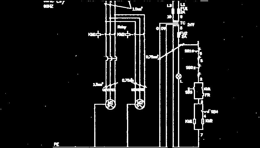
23 CIRCUIT DIAGRAM - 23-


24 CE - 24-

25 CE - 25-
Horizontal and Vertical. Metal Cutting Band Saw MODEL: BS-115
 Horizontal and Vertical Metal Cutting Band Saw MODEL: BS-5 SAFETY. Know your band saw. Read the operator s Manual carefully. Learn the operations, applications and limitation.. Use recommended accessories.
Page 1 Instructions Manual for EB-330DSC (B075) 27/04/201 INSTRUCTION MANUAL
 27/04/201 INSTRUCTION MANUAL") Page 1 Instructions Manual for EB-330DSC (B075) 27/04/201 INSTRUCTION MANUAL EB-330DSC Swivel Head-Dual Mitre Metal Cutting Band Saw with Conveyor System (415V) 295 x 230mm (W x H) Rectangle B075 Page
Page 1 Instructions Manual for EB-330DSC (B075) 27/04/201 INSTRUCTION MANUAL EB-330DSC Swivel Head-Dual Mitre Metal Cutting Band Saw with Conveyor System (415V) 295 x 230mm (W x H) Rectangle B075 Page
METAL CUTTING BAND SAW MODEL:BS-460G. Operation manual
 METAL CUTTING BAND SAW MODEL:BS-460G Operation manual Table of contents 1. General safety rules 2. Production application and usage 3. Technical specifications 4. Transportation and installation 5. Assembly
VARIABLE SPEED WOOD LATHE
 MODEL MC1100B VARIABLE SPEED WOOD LATHE INSTRUCTION MANUAL Please read and fully understand the instructions in this manual before operation. Keep this manual safe for future reference. Version: 2015.02.02
METAL CUTTING BAND SAW Model: BS-712R. 7 X12 Rectangle (180x300mm) FPM 50Hz. Blade Size: 3/4 x0.032 x93 (19X0.
 FPM 50Hz. Blade Size: 3/4 x0.032 x93 (19X0.") METAL CUTTING BAND SAW Model: BS-7R Specifications Cutting Capacity: 7 Round (80mm) 7 X Rectangle (80x300mm) Blade Speed: 86-3-78-60 FPM 60Hz 7-0-8-7 FPM 50Hz Blade Size: 3/ x0.03 x93 (9X0.9X360mm) Operation
METAL CUTTING BAND SAW Model: BS-7R Specifications Cutting Capacity: 7 Round (80mm) 7 X Rectangle (80x300mm) Blade Speed: 86-3-78-60 FPM 60Hz 7-0-8-7 FPM 50Hz Blade Size: 3/ x0.03 x93 (9X0.9X360mm) Operation
D R I L L - G R I N D E R S BL 13D-2
 D R I L L - G R I N D E R S BL 13D-2 2 Table of contents 1. General safety rules for all machines 3 2. Additional safety rules 4 3. Features 4 4. Specification 4 5. Operation 4 5.1 Assemble the fixture
GENERAL OPERATIONAL PRECAUTIONS PRECAUTIONS ON USING DISC GRINDER
 GENERAL OPERATIONAL PRECAUTIONS WARNING! When using electric tools, basic safety precautions should always be followed to reduce the risk of fire, electric shock and personal injury, including the following.
STARTING SERIAL NUMBER PARTS LIST FOR. Wellsaw MODEL 600 METAL CUTTING BAND SAW
 STARTING SERIAL NUMBER 11075 PARTS LIST FOR Wellsaw MODEL 600 METAL CUTTING BAND SAW Wellsaw 2829 N. Burdick, Kalamazoo, MI 49004 Phone: 269-345-1132 Fax: 269-345-0095 Rev 171005 INSTALLATION, OPERATION
TB & SB Series Drill Presses
 TB & SB Series Drill Presses OWNERS MANUAL BENCH AND FLOOR DRILL PRESS TB-16 Series & SB-16-25-32-Series FOR YOUR OWN SAFETY AND OPTIMUM OPERATION READ INSTRUCTION MANUAL BEFORE OPERATING DRILL PRESS RETAIN
Cut-Off Machine Model CC 14SE
 Cut-Off Machine Model CC 14SE Handling instructions NOTE: Before using this Electric Power Tool, carefully read through these HANDLING INSTRUCTIONS to ensure efficient, safe operation. It is recommended
 GENERAL OPERATIONAL PRECAUTIONS WARNING! When using electric tools, basic safety precautions should always be followed to reduce the risk of fire, electric shock and personal injury, including the following.
VARIABLE SPEED WOOD LATHE. Model DB900 INSTRUCTION MANUAL
 VARIABLE SPEED WOOD LATHE Model DB900 INSTRUCTION MANUAL 1007 TABLE OF CONTENTS SECTION...PAGE Technical data.. 1 General safety rules....1-3 Specific safety rules for wood lathe.....3 Electrical information.4
Model SQM-2AC Squaring Module Rev TABLE OF CONTENTS
 92-0714 Rev. 970428 Model SQM-2AC Squaring Module TABLE OF CONTENTS CUSTOMER MESSAGE Inside Front Cover SAFETY PRECAUTIONS 3 GENERAL DESCRIPTION 6 SPECIFICATIONS 7 MAINTENANCE 8 OPERATION 9 CUTTING SPEEDS
METAL CUTTING BAND SAW MODEL: GK-4235
 METAL CUTTING BAND SAW MODEL: GK-4235 Operation manual Table of contents 1. Safety... 1 2. Specification... 4 3. Identification... 5 4. Set up... 7 4.1 Moving & placing base unit... 7 4.2 Clean up... 8
Quick Set Dovetail Jig
 Quick Set Dovetail Jig FOR HELP OR ADVISE ON THIS PRODUCT PLEASE CALL OUR CUSTOMER SERVICE HELP LINE : 01509 500359 THE MANUFACTURER RESERVES THE RIGHT TO ALTER THE DESIGN OR SPECIFICATION TO THIS PRODUCT
Cyclone Upcut Cut off saw
 Cyclone Upcut Cut off saw Operation manual WARNING The operator must thoroughly read and understand this manual before operating the cut off saw or starting any servicing. All safety and warning instructions
12mm (Max) 6mm (Max) 82mm (Max) 12mm (Max) 6mm (Max)
 6mm (Max) 82mm (Max) 12mm (Max) 6mm (Max)") 1 1 2 2 3 3 82mm (Max) 12mm (Max) 12mm (Max) 6mm (Max) 4 4 5 6 8 6mm (Max) 0.5 0mm 1 5 6 7 7 8 9 9 A = B 10 11 12 D B 1 13 14 15 0 C A D E 16 17 18 F G D B N H J G I K 19 A 20 G L 21 C K 1mm L M 1mm 22
1 1 2 2 3 3 82mm (Max) 12mm (Max) 12mm (Max) 6mm (Max) 4 4 5 6 8 6mm (Max) 0.5 0mm 1 5 6 7 7 8 9 9 A = B 10 11 12 D B 1 13 14 15 0 C A D E 16 17 18 F G D B N H J G I K 19 A 20 G L 21 C K 1mm L M 1mm 22
Circular Saw MODEL MT581. WARNING: For your personal safety, READ and UNDERSTAND before using. SAVE THESE INSTRUCTIONS FOR FUTURE REFERENCE.
 ENGLISH Circular Saw MODEL MT58 005337 DOUBLE INSULATION I N S T R U C T I O N M A N U A L WARNING: For your personal safety, READ and UNDERSTAND before using. SAVE THESE INSTRUCTIONS FOR FUTURE REFERENCE.
8"x 14" Horizontal Band Saw SPECIFICATIONS. Always read instructions before using power tools. Always wear safety goggles. Wear hearing protection
 Always read instructions before using power tools Always wear safety goggles Wear hearing protection Capacity...90 8" (200mm) 8" x 11" (200 x 280mm) 2.4" x 13.8" (60 x 350mm) Capacity...45 5.5" (140mm)
Tapping Screw (W/Flange) 46 Cord Armor 47 Tube (D) 48 Cord. 45 Cord Clip. Tapping Screw (W/Flange) 10 Gear Cover Ass'y. 12 Socket (B) Ass'y
 46 Cord Armor 47 Tube (D) 48 Cord. 45 Cord Clip. Tapping Screw (W/Flange) 10 Gear Cover Ass'y. 12 Socket (B) Ass'y") W8VB The exploded assembly drawing should be used only for authoized service center. W8VB Item No. Part time 1 Magnetic Hex. Socket 2 Sub Stopper 3 O-Ring (S-16) 4 Locator (A) 5 Lock Sleeve (A) 6 O-Ring
W8VB The exploded assembly drawing should be used only for authoized service center. W8VB Item No. Part time 1 Magnetic Hex. Socket 2 Sub Stopper 3 O-Ring (S-16) 4 Locator (A) 5 Lock Sleeve (A) 6 O-Ring
SAFETY AND OPERATING MANUAL
 SAFETY AND OPERATING MANUAL BladeRunner X2 WX572 9 10 8 11 5 7 12 6 20 1 2 4 3 14 13 15 A2 A1 17 18 B2 B1 1 2 1 2 19 B3 3 4 2 C 1 D1 D1 C 2 1 E1 D2 1 2 E2 1 2 F G1 G1 F OFF ON G2 G3 H1 H2 I1 I2 I1 I2 J
Mini Max 20 BAND SAW
 OPERATING PROCEDURE FOR: Mini Max 20 BAND SAW SAFETY RULES: Warning: Willful violations of these safety rules, disruptive actions or horseplay may result in loss of the privilege to use the tools and machinery
Model 204B-EM Elbow Mandrels Rev TABLE OF CONTENTS
 92-0697 Rev. 970131 Model 204B-EM Elbow Mandrels TABLE OF CONTENTS CUSTOMER MESSAGE Inside Front Cover SAFETY PRECAUTIONS 3 GENERAL DESCRIPTION 6 MAINTENANCE 7 OPERATION 8 TROUBLE SHOOTING 11 ACCESSORIES
12 SHEAR, PRESS BRAKE &SLIPROLL
 12 SHEAR, PRESS BRAKE &SLIPROLL OPERATION MANUAL SPECIFICATION Cpacity: Roller : Die set sizes: Weight: 1mm thick (20gauge), 305 mm (12 ) width 38mm(1-1/2 ) 101.6mm(4 ), 76.2mm(3 ), 50.8mm (x2)[2 9x2]],
ELECTRIC SLIP ROLL MACHINE. Model: ESR-1300X2.5/ESR-1300X4.5 ESR-1550X3.5/ESR-1580X2.0
 ELECTRIC SLIP ROLL MACHINE Model: ESR-1300X2.5/ESR-1300X4.5 ESR-1550X3.5/ESR-1580X2.0 Operation Manual Table of contents I MAIN SPECIFICATION...2 II SAFETY INSTRUCTIONS.. 2 III OPERATION INSTRUCTIONS..4
WARNING! Read and understand the entire instruction manual before attempting set-up or operation of this machine!
 ! WARNING! Read and understand the entire instruction manual before attempting set-up or operation of this machine! 1. This machine is designed and intended for use by properly trained and experienced
Recipro Saw MODEL JR3020. WARNING: For your personal safety, READ and UNDERSTAND before using. SAVE THESE INSTRUCTIONS FOR FUTURE REFERENCE.
 ENGLISH Recipro Saw MODEL JR3020 002479 DOUBLE INSULATION I N S T R U C T I O N M A N U A L WARNING: For your personal safety, READ and UNDERSTAND before using. SAVE THESE INSTRUCTIONS FOR FUTURE REFERENCE.
Angle Grinder MODEL 9553B MODEL 9555B
 ENGLISH Angle Grinder MODEL 9553B MODEL 9555B 006649 DOUBLE INSULATION I N S T R U C T I O N M A N U A L WARNING: For your personal safety, READ and UNDERSTAND before using. SAVE THESE INSTRUCTIONS FOR
GENERAL OPERATIONAL PRECAUTIONS PRECAUTIONS ON USING CUT-OFF MACHINE
 GENERAL OPERATIONAL PRECAUTIONS WARNING! When using electric tools, basic safety precautions should always be followed to reduce the risk of fire, electric shock and personal injury, including the following.
GENERAL OPERATIONAL PRECAUTIONS
 GENERAL OPERATIONAL PRECAUTIONS WARNING! When using electric tools, basic safety precautions should always be followed to reduce the risk of fire, electric shock and personal injury, including the following.
INSTRUCTION BOOKLET AND WARRANTY INFORMATION 6 BENCH GRINDER
 INSTRUCTION BOOKLET AND WARRANTY INFORMATION 6 BENCH GRINDER Part No.: SW1250 PLEASE READ CARE AND SAFETY INSTRUCTIONS BEFORE USE SPECIFICATIONS Part No.: SW1250 Input Voltage: 240V Frequency: 50Hz Rated
INSTRUCTION MANUAL MODEL SE-912 METAL CUTTING BANDSAW MACHINE
 INSTRUCTION MANUAL MODEL SE-912 METAL CUTTING BANDSAW MACHINE 724 Robbins Road Grand Haven, MI 49417 Phone: 616-842-7110, 800-937-3253 Fax: 616-842-0859, 800-846-3253 Web: www.dakecorp.com E-mail: customerservice@dakecorp.com
MODEL W1.0X305A(12 ) MODEL W1.0X610A(24 ) HAND BENDING BRAKE ASSEMBLY&OPERATING INSTRUCTION
 MODEL W1.0X610A(24 ) HAND BENDING BRAKE ASSEMBLY&OPERATING INSTRUCTION") MODEL W1.0X305A(12 ) MODEL W1.0X610A(24 ) HAND BENDING BRAKE ASSEMBLY&OPERATING INSTRUCTION 1 SAVE THIS MANUAL You will need the manual for the safety warning and precautions, assembly instructions, operating
MODEL W1.0X305A(12 ) MODEL W1.0X610A(24 ) HAND BENDING BRAKE ASSEMBLY&OPERATING INSTRUCTION 1 SAVE THIS MANUAL You will need the manual for the safety warning and precautions, assembly instructions, operating
LS12/LS12C. LS12C Item # LS12 Item # /10 LORTONE, inc Cyrus Way, Mukilteo, WA U.S.A
 LORTONE LS12C Item # 053-093 LS12 Item # 053-090 LS12/LS12C Instructions and Parts List The LS12 is a quiet, fully enclosed, professional quality 12 slab saw. It comes equipped with a powerful screw-feed
MODEL 7000 BEVEL-MILL
 MODEL 7000 BEVEL-MILL HECK INDUSTRIES P.O. BOX 425 HARTLAND, MI 48353 TOLL FREE: 800-886-5418 PHONE: 810-632-5400 FAX: 810-632-6640 WWW.HECKIND.NET INSTRUCTION MANUAL Save This Manual You will need the
MI MI OPERATING MANUAL
 MODEL NO.: MI-76100 MI-76150 OPERATING MANUAL RULES for SAFE OPERATION MAGNUM INDUSTRIAL MI-76100 and MI 76150 DRILL PRESSES To help ensure safe operation, please take a moment to learn the how to operate
Electric Router. Please read and fully understand the instructions in this manual before operation and keep this manual safe for future
 Electric Router FOR HELP OR ADVISE ON THIS PRODUCT PLEASE CALL OUR CUSTOMER SERVICE HELP LINE : 0509 500400 THE MANUFACTURER RESERVES THE RIGHT TO ALTER THE DESIGN OR SPECIFICATION TO THIS PRODUCT WITHOUT
Powermatic Model 31A Combination Belt-Disk Sander
 OPERATING PROCEDURE FOR: Powermatic Model 31A Combination Belt-Disk Sander INTRODUCTION: The combination belt-disk sander is used to sand the edges of boards. It can be used to smooth the edge or to remove
Elderfield & Hall, Inc., Kama Bandsaw AD 105S. Instruction Manual: Introduction to the Manual. General Precautions. Equipment. Machine.
 Elderfield & Hall, Inc., www.kooltools.com 10901 McBride Lane, Knoxville TN, 37932. Phone: 865.671.7682. Fax: 865.671.7686. Email: bob@kooltools.com Kama Bandsaw AD 105S 110 Volt, Single Phase 2 ¼ HP Portable
Instructions for Stone Cutting Machine
 Technical data Kg. Instructions for Stone Cutting Machine SCM600 3HP 2800rpm IP55 SCM800 3HP 2800rpm IP55 SCM1000 2800rpm IP55 SCM1200 2800rpm IP55 L=600 B=85(165) L=800 B=85(175) 500x510 0 or 45 600lt/h
Cut-Off Machine CC 14SF. Read through carefully and understand these instructions before use. Handling instructions
 Cut-Off Machine CC 14SF Read through carefully and understand these instructions before use. Handling instructions GENERAL OPERATIONAL PRES WARNING! When using electric tools, basic safety precautions
Tube Facing Tool.
 www.swagelok.com Tube Facing Tool This manual contains important information for the safe and effective operation of the Swagelok TF72 series tube facing tool. Users should read and understand its contents
OPERATORS MANUAL. Band Saw by. Model SFI-60. (877) East (800) West
 East (800) West") OPERATORS MANUAL Band Saw by INVICTA Model SFI-60 INVICTA USA (877) 308-6423 - East (800) 499-4682 - West English Version General Instructions Thank you for purchasing this quality machine from INVICTA.
OPERATORS MANUAL Band Saw by INVICTA Model SFI-60 INVICTA USA (877) 308-6423 - East (800) 499-4682 - West English Version General Instructions Thank you for purchasing this quality machine from INVICTA.
GENERAL OPERATIONAL PRECAUTIONS
 GENERAL OPERATIONAL PRECAUTIONS WARNING! When using electric tools, basic safety precautions should always be followed to reduce the risk of fire, electric shock and personal injury, including the following.
Hinge Boring/Insertion Machine Set Up And Operation Instructions
 Hinge Boring/Insertion Machine Set Up And Operation Instructions Manufactured In The USA By: Thompson Industries, Inc. 1018 Crosby Avenue, Sycamore, IL. 60178-0127 Ph:815-899-6670 Fax:815-899-1918 Thank
HORIZONTAL/VERTICAL BANDSAW INSTRUCTIONS. Item #20650
 HORIZONTAL/VERTICAL BANDSAW INSTRUCTIONS Item #20650 The EASTWOOD HORIZONTAL/VERTICAL BANDSAW is a heavy-duty professional quality tool ruggedly designed for many years of reliable service. This versatile
ROUND BENDING MACHINE Model: RBM30
 ROUND BENDING MACHINE Model: RBM30 Operation Manual SAVE THIS MANUAL:You will need the manual for the safety warnings and precautions, assembly instructions, operating and maintenance procedures, parts
18 GAUGE ELECTRIC METAL SHEAR
 241-9895 18 GAUGE ELECTRIC METAL SHEAR Operator s Manual SAVE THIS MANUAL You will need this manual for safety instructions, operating procedures and warranty. Put it and the original sales receipt in
Sander. Finishing INSTRUCTION MANUAL. MODEL BO4550 MODEL BO45502 Without dust bag and punch plate DOUBLE INSULATION SPEC IF1 CAT1 ONS.
 Finishing INSTRUCTION MANUAL Sander MODEL BO4550 MODEL BO4550 Without dust bag and punch plate DOUBLE INSULATION SPEC IF CAT ONS Pad size No load speed lopml Dimensions (L x W x H) Net weight mmxloomm
ENGLISH (Original instructions) INSTRUCTION MANUAL. Drill DS4012 DOUBLE INSULATION. IMPORTANT: Read Before Using.
 INSTRUCTION MANUAL. Drill DS4012 DOUBLE INSULATION. IMPORTANT: Read Before Using.") ENGLISH (Original instructions) INSTRUCTION MANUAL Drill DS402 05402 DOUBLE INSULATION IMPORTANT: Read Before Using. ENGLISH (Original instructions) SPECIFICATIONS Model DS402 Capacities Steel 3 mm Wood
ENGLISH (Original instructions) INSTRUCTION MANUAL Drill DS402 05402 DOUBLE INSULATION IMPORTANT: Read Before Using. ENGLISH (Original instructions) SPECIFICATIONS Model DS402 Capacities Steel 3 mm Wood
HOLE CUTTER SHARPENER ASSEMBLY & SERVICE MANUAL
 HOLE CUTTER SHARPENER ASSEMBLY & SERVICE MANUAL WARNING You must thoroughly read and understand this manual before operating the equipment, paying particular attention to the Warning & Safety instructions.
Pro Series. DK4100 and DK5100 INSTRUCTIONAL MANUAL. The Blue Mark of Quality. DK5109
 Pro Series DK4100 and DK5100 INSTRUCTIONAL MANUAL The Blue Mark of Quality. DK5109 20041101 Table of Contents 1 Congratulations on choosing a Kreg Pro Series Pocket Hole Machine! Be sure to read the instructions
Lumber Smith. Assembly Manual. If you are having problems assembling the saw and need assistance, please contact us at:
 Lumber Smith Assembly Manual If you are having problems assembling the saw and need assistance, please contact us at: 804-577-7398 info@lumbersmith.com 1 Step 1 Safety Carefully read the Owners Manual.
GEARED HEAD DRILL / MILL MACHINE INSTRUCTION MANUAL
 www.industrialtool.com.au GEARED HEAD DRILL / MILL MACHINE INSTRUCTION MANUAL READ CAREFULLY AND UNDERSTAND THESE INSTRUCTIONS BEFORE USE. LIMITED WARRANTY Industrial Tool & Machinery Sales (hereinafter
Agricultural Mechanics and Technology Power Tool Safety Rules
 Agricultural Mechanics and Technology Power Tool Safety Rules Name: BAND SAW Use: Cutting curves, circles and irregular shapes. 1. Use clean SHARP blades. 2. The teeth should always point DOWN. 3. Adjust
HAND HELD SAW W MILL
 HAND HELD SAW W MILL 92247 ASSEMBLY AND OPERATING INSTRUCTIONS 3491 Mission Oaks Blvd., Camarillo, CA 93011 Visit our Web site at http://www.harborfreight.com Copyright 2004 by Harbor Freight Tools. All
SAVE THIS FOR FUTURE REFERENCE THIS PRODUCT IS FOR PROFESSIONAL LABORATORY USE ONLY USER'S MANUAL
 DENTAL, INC. TECHNICAL BULLETIN G801-022510 5860 FLYNN CREEK ROAD READ ALL INSTRUCTIONS P.O. BOX 106 BEFORE PROCEEDING COMPTCHE, CALIFORNIA, U.S.A. 95427-0106 SAVE THIS FOR FUTURE REFERENCE www.wellsdental.com
ROTARY HAMMER OWNER'S MANUAL
 ROTARY HAMMER OWNER'S MANUAL WARNING: Read carefully and understand all INSTRUCTIONS before operating. Failure to follow the safety rules and other basic safety precautions may result in serious personal
20-Inch x 20-Inch Semi Automatic Horizontal Cut-Off Band Saw Model: 7060
 Operating Instructions Parts Manual 20-Inch x 20-Inch Semi Automatic Horizontal Cut-Off Band Saw Model: 7060 WHM TOOL GROUP 2420 Vantage Drive Elgin, Illinois 60124 Part No. 5511736 Ph.: 800-274-6848 Revision
ENGLISH (Original instructions) INSTRUCTION MANUAL. Drill DOUBLE INSULATION. IMPORTANT: Read Before Using.
 INSTRUCTION MANUAL. Drill DOUBLE INSULATION. IMPORTANT: Read Before Using.") ENGLISH (Original instructions) INSTRUCTION MANUAL Drill 64 642 643 007894 DOUBLE INSULATION IMPORTANT: Read Before Using. ENGLISH (Original instructions) SPECIFICATIONS Model 64 642 643 Capacities Steel
ENGLISH (Original instructions) INSTRUCTION MANUAL Drill 64 642 643 007894 DOUBLE INSULATION IMPORTANT: Read Before Using. ENGLISH (Original instructions) SPECIFICATIONS Model 64 642 643 Capacities Steel
SB-32V Drill Press OWNERS MANUAL
 724 Robbins Road, Grand Haven, MI 49417 Phone: 616-842-7110 800-937-3253 Fax: 616-842-0859 800-846-3253 Web: www.dakecorp.com E-mail: customerservice@dakecorp.com SB-32V Drill Press OWNERS MANUAL FOR YOUR
ENGLISH (Original instructions) INSTRUCTION MANUAL. Drill MT600 MT601 DOUBLE INSULATION. IMPORTANT: Read Before Using.
 INSTRUCTION MANUAL. Drill MT600 MT601 DOUBLE INSULATION. IMPORTANT: Read Before Using.") ENGLISH (Original instructions) INSTRUCTION MANUAL Drill MT600 MT60 003635 DOUBLE INSULATION IMPORTANT: Read Before Using. ENGLISH (Original instructions) SPECIFICATIONS Model MT600 MT60 Capacities Steel
ENGLISH (Original instructions) INSTRUCTION MANUAL Drill MT600 MT60 003635 DOUBLE INSULATION IMPORTANT: Read Before Using. ENGLISH (Original instructions) SPECIFICATIONS Model MT600 MT60 Capacities Steel
Core EZ. Operating Manual. Toll Free B East Broadway Avenue Tampa, FL 33619
 Operating Manual 3702 West Central Avenue Santa Ana, CA 92704 Toll Free 1-866-987-7297 11 High Street Suffield, CT 06078 www.ussaws.com 8004B East Broadway Avenue Tampa, FL 33619 Introduction This manual
Drill INSTRUCTION MANUAL. WARNING: For your personal safety, READ and UNDERSTAND before using. SAVE THESE INSTRUCTIONS FOR FUTURE 1 REFERENCE.
 ENGLISH (Original instructions) INSTRUCTION MANUAL Drill 6411 6412 6413 007894 DOUBLE INSULATION WARNING: For your personal safety, READ and UNDERSTAND before using. SAVE THESE INSTRUCTIONS FOR FUTURE
ELECTRIC TUBE ROLLER
 41238-0000 ELECTRIC TUBE ROLLER OPERATING INSTRUCTIONS & SERVICE MANUAL Rev: A, 8/20/2007 TO REDUCE THE RISK OF INJURY AND EQUIPMENT DAMAGE USER MUST READ AND UNDERSTAND OPERATOR S MANUAL. Thomas C. Wilson,
METAL CUTTING BAND SAW MACHINE
 METAL CUTTING BAND SAW MACHINE MODEL: 330/330A INSTRUCTION MANUAL 330/330A -051114-R1 ! WARNING! Some dust created by power sanding, sawing, grinding, drilling, and other construction activities contains
Cordless Circular Saw with Dust Collection
 ENGLISH Cordless Circular Saw with Dust Collection MODEL 506D MODEL 5036D MODEL 5046D 003 I N S T R U C T I O N M A N U A L WARNING: For your personal safety, READ and UNDERSTAND before using. SAVE THESE
Dust Collector. Model No: DC2200 (FM300S)
") Dust Collector Model No: DC2200 (FM300S) GENERAL SAFETY INSTRUCTIONS Before attempting to operate this machine, it is important that you read, understand and follow these instructions very carefully. They
Dust Collector Model No: DC2200 (FM300S) GENERAL SAFETY INSTRUCTIONS Before attempting to operate this machine, it is important that you read, understand and follow these instructions very carefully. They
20 TON HyDRAULIC SHOP PRESS with GRID GUARD 06/2015 INSTRUCTION MANUAL MODEL: KHP-20T-GG COPYRIGHT 2015 ALL RIGHTS RESERVED BY KING CANADA TOOLS INC.
 06/2015 20 TON HyDRAULIC SHOP PRESS with GRID GUARD MODEL: KHP-20T-GG INSTRUCTION MANUAL COPYRIGHT 2015 ALL RIGHTS RESERVED BY KING CANADA TOOLS INC. warranty INFORMATION 2-yEAR LIMITED WARRANTY FOR THIS
Lumber Smith. Owners Manual. If you are having problems assembling the saw and need assistance, please contact us at:
 Lumber Smith Owners Manual If you are having problems assembling the saw and need assistance, please contact us at: 804-577-7398 info@lumbersmith.com 1 General Safety Instructions Failure to follow these
Metals can be bought from suppliers in standardized forms and sizes, such as round,
 1.4 METAL CUTTING BAND SAWS: Metals can be bought from suppliers in standardized forms and sizes, such as round, rectangular or square bar stock or in the form of large sheets (plates). Bar stock normally
8 TONNE LOG SPLITTER
 8 TONNE LOG SPLITTER MODEL NO: LOGBUSTER 9 PART NO: 3402043 OPERATION & MAINTENANCE INSTRUCTIONS LS03/16 INTRODUCTION Thank you for purchasing this CLARKE 8 Tonne Log Splitter. Before attempting to use
10 BANDSAW OPERATING INSTRUCTIONS MODEL: W715
 Machinery & Tooling at its best! 10 BANDSAW OPERATING INSTRUCTIONS MODEL: W715 Charnwood, Cedar Court, Walker Road, Bardon, Leicestershire, LE67 1TU Tel. 01530 516926 Fax. 01530 516929 email; sales@charnwood.net
10" Wet Tile Cutting Saw
 8035735 10" Wet Tile Cutting Saw Owner s Manual Read and understand all instructions before operation. Keep this manual for future reference pg. 2 SPECIFICATIONS ITEM DESCRIPTION Overall Dimensions (saw
Parts List, Operating & Maintenance Manual for Wells No. 5 Metal Cutting Bandsaws
 M A D E I N U. S. A. Parts List, Operating & Maintenance Manual for Wells No. 5 Metal Cutting Bandsaws M A D E I N U. S. A. 170706 2829 N. Burdick St. Kalamazoo, MI 49004 Phone: (269)345-1132 Fax: (269)345-0095
Operating and Maintenance Instructions Keep for future reference
 Operating and Maintenance Instructions Keep for future reference TM400 Log Splitter 1 Index SAFETY... 3 LABELS.... 4 QUICK GUIDE including storage and transport... 5 IN-DEPTH INSTRUCTIONS.... 6 OPERATING
EllisSaw.com. EllisSaw.com P.O. Box Verona, WI
 P.O. Box 9019 Verona, WI 9-019 GENERAL OPERATING & SAFETY INSTRUCTIONS * READ INSTRUCTIONS BEFORE USE * CAUTION: Disconnect power supply cord from power source when doing repair work or changing belt.
3HP BAG CYCLONE DUST COLLECTOR MANUAL
 3HP BAG CYCLONE DUST COLLECTOR MANUAL LAGUNA TOOLS 2072 Alton Parkway Irvine, California 92606 Ph: 800.234.1976 www.lagunatools.com 2018, Laguna Tools, Inc. LAGUNA and the LAGUNA Logo are the registered
Introduction to Carpentry Power Tools
 Youth Explore Trades Skills Introduction to Carpentry Power Tools Description s use power tools every day, and the ability to use these tools correctly and safely is paramount. In this Activity Plan, students
Policy Sponsor: Assistant Vice President Facilities Management. Responsible Unit: Trade Services
 Safe Work Instructions for Powered Mitre Cut Hack Saw (Mitercut Model 220M) Policy Sponsor: Assistant Vice President Facilities Management Responsible Unit: Trade Services Approval Date: November 2016
OPERATING INSTRUCTIONS AND PARTS LISTS
 3889560 REEL ALIGNMENT GAGE OPERATING INSTRUCTIONS AND PARTS LISTS WARNING You must thoroughly read and understand this manual before operating the equipment, paying particular attention to the Warning
FOR YOUR SAFETY: READ ALL INSTRUCTIONS CAREFULLY
 MODEL 2020F FOR YOUR SAFETY: READ ALL INSTRUCTIONS CAREFULLY Table of Contents General safety instructions for Power Tools 1 Main specification 2 Unpacking and checking contents 2 List of loose parts in
VARIABLE SPEED BECH LATHE
 VARIABLE SPEED BECH LATHE Instruction Manual Please read this instruction manual thoroughly and follow all directions carefully. 1 Important Safety Instructions READ ALL INSTRUCTIONS AND WATNINGS BEFORE
Inventory (Figure 2)
") MODEL T10127 12" SPIRAL CUTTERHEAD INSTRUCTIONS The Model T10127 indexable insert spiral cutterhead is designed to replace the straightknife cutterhead from the Grizzly jointer Model G0609. The total procedure
MODEL T10127 12" SPIRAL CUTTERHEAD INSTRUCTIONS The Model T10127 indexable insert spiral cutterhead is designed to replace the straightknife cutterhead from the Grizzly jointer Model G0609. The total procedure
Instruction Manual. Version
 SW-100H Instruction Manual Version 1 20170830 Safety rules Make sure your work area is cleared of uninvited people and obstacles every time before you start operating the machine. Never step or stand
FBX1104P FBX1104 FBX1106P FBX1106
 FBX1104P FBX1104 FBX1106P FBX1106 Second edition : September 2004 No. 040037 INTRODUCTION Thank you for your purchasing Kansai Special's FBX Series. Read and study this instruction manual carefully before
ENGLISH (Original instructions) INSTRUCTION MANUAL. Hammer Drill HP1630 HP1631 DOUBLE INSULATION. IMPORTANT: Read Before Using.
 INSTRUCTION MANUAL. Hammer Drill HP1630 HP1631 DOUBLE INSULATION. IMPORTANT: Read Before Using.") ENGLISH (Original instructions) INSTRUCTION MANUAL Hammer Drill HP630 HP63 008892 DOUBLE INSULATION IMPORTANT: Read Before Using. ENGLISH (Original instructions) SPECIFICATIONS Model HP630 HP63 Concrete
ENGLISH (Original instructions) INSTRUCTION MANUAL Hammer Drill HP630 HP63 008892 DOUBLE INSULATION IMPORTANT: Read Before Using. ENGLISH (Original instructions) SPECIFICATIONS Model HP630 HP63 Concrete
Grizzly Drill Press SOP
 Grizzly Drill Press SOP Drill Press is wired to run on 0V. Drill Press has a built in light with a ON/OFF switch. Never hold a workpiece by hand while drilling. Clamp it down or hold it in a vice. Never
12 TON HYDRAULIC SHOP PRESS. Instruction Manual. Please read this instruction manual carefully before use.
 12 TON HYDRAULIC SHOP PRESS Instruction Manual Please read this instruction manual carefully before use. IMPORTANT PLEASE READ THESE INSTRUCTIONS CAREFULLY. NOTE THE SAFETY INSTRUCTIONS AND WARNINGS. USE
Operating, Servicing, and Safety Manual Model # 100 Standard Hydraulic Tubing Notcher Model #100-U Heavy Duty Hydraulic Tubing Notcher
 Operating, Servicing, and Safety Manual Model # 100 Standard Hydraulic Tubing Notcher Model #100-U Heavy Duty Hydraulic Tubing Notcher Model # 100 Standard Model #100-U Heavy Duty CAUTION: Read and Understand
9 X 16 METAL CUTTING BAND SAW
 operating manual & parts list 9683314 9 X 16 METAL CUTTING BAND SAW Read carefully and follow all safety rules and operating instructions before first use of this product. 9641488.01-1216 DESCRIPTION 9
MILLING \ DRILLING MACHINE
 MILLING \ DRILLING MACHINE MODEL 400HS/400S2F 400HC/400C2F 400-070620-R2 INSTRUCTION MANUAL ! WARNING! Some dust created by power sanding, sawing, grinding, drilling, and other construction activities
Hammer Drill MODEL HP1500 MODEL HP1501 MODEL HP1510
 ENGLISH Hammer Drill MODEL HP500 MODEL HP50 MODEL HP50 002395 DOUBLE INSULATION I N S T R U C T I O N M A N U A L WARNING: For your personal safety, READ and UNDERSTAND before using. SAVE THESE INSTRUCTIONS
SECTION 9: PARTS. Headstock
 SECTION 9: PARTS We do our best to stock replacement parts when possible, but we cannot guarantee that all parts shown are available for purchase. Call (800) 52-4777 or visit www.grizzly.com/parts to check
CT Box and Pan Brake User Manual
 CT153 12 Box and Pan Brake User Manual Important Safety Precautions Plead read all the instructions before using this tool. 1) Always keep your work area clean. Cluttered areas invite injuries. 2) Do not
Instruction Manual 13MM DRILL PRESS. Model SROM1199. Our tool range has you covered for DIY. Whatever the job, make light work of it with MAKO tools.
 Instruction Manual 13MM DRILL PRESS Model SROM1199 Our tool range has you covered for DIY. Whatever the job, make light work of it with MAKO tools. PRODUCT FEATURES: 1. Pulley Cover 9. Feed Handle 2. Motor
Operating Instructions and Parts Manual. 10 x 16 Horizontal Band Saw Models J-7020, J-7040
 Operating Instructions and Parts Manual 10 x 16 Horizontal Band Saw Models J-7020, J-7040 JET 427 New Sanford Road LaVergne, Tennessee 37086 Part No. M-414472 Ph.: 800-274-6848 Revision C2 03/2014 www.jettools.com
2-Speed Hammer Drill HP2030 HP2031 INSTRUCTION MANUAL
 ENGLISH (Original instructions) INSTRUCTION MANUAL 2-Speed Hammer Drill HP2030 HP203 002466 DOUBLE INSULATION WARNING: For your personal safety, READ and UNDERSTAND before using. SAVE THESE INSTRUCTIONS
LPK1550 Hydraulic Crimping Tool 15-ton
 SERVICE MANUAL LPK1550 Hydraulic Crimping Tool 15-ton Serial Code FYF Read and understand all of the instructions and safety information in this manual before operating or servicing this tool. Register
SAVE THIS FOR FUTURE REFERENCE THIS PRODUCT IS FOR PROFESSIONAL LABORATORY USE ONLY USER'S MANUAL
 DENTAL, INC. TECHNICAL BULLETIN Q827-022510 5860 FLYNN CREEK ROAD READ ALL INSTRUCTIONS P.O. BOX 106 BEFORE PROCEEDING COMPTCHE, CALIFORNIA, U.S.A. 95427 SAVE THIS FOR FUTURE REFERENCE www.wellsdental.com