Victory Fire Door Inspections
|
|
|
- Justina Skinner
- 5 years ago
- Views:
Transcription

1
2 Vickie Evans, FDAI Over 30 years in door and hardware industry DHI instructor and Education Advocate Certified Fire Door Inspector


3 To compartmentalize a building Deter the spread of smoke and flames Fire door assemblies are of no value unless they are properly maintained and are closed and latched in the event of a fire
4
5 Most state fire codes currently require fire door assemblies to be maintained in accordance with NFPA 80 Since 2007, NFPA 80 has required fire door assembly inspections as part of Chapter 5 Care and Maintenance IFC Requires maintenance in accordance with NFPA 80 NFPA Requires inspection and testing in accordance with NFPA 80
6 states testing shall be performed by a qualified person with knowledge and understanding Requires a visual and operational test Acceptance test shall include closing the door by all means of activation A record of the inspection and testing is required
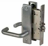
7 Rule # 1 All fire door assemblies shall consist of: Labeled Door Frames Labeled Fire Doors Labeled / Listed Hardware & Glazing
8 Rule # 2 Any field modification to a labeled product must be approved by the testing laboratory that listed/ labeled the product.
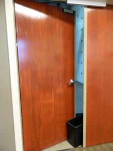
9 Swing Freely Self-Closing Self-Latching All swinging fire doors shall be closed and latched at the time of fire


10 Labels Fire rated labels properly attached and legible
11 Ensure label rating is sufficient for wall rating Door Label can be ¾ rating of wall rating Cover label when painting frame and door Labels are door specific and shall not be removed and placed on another door
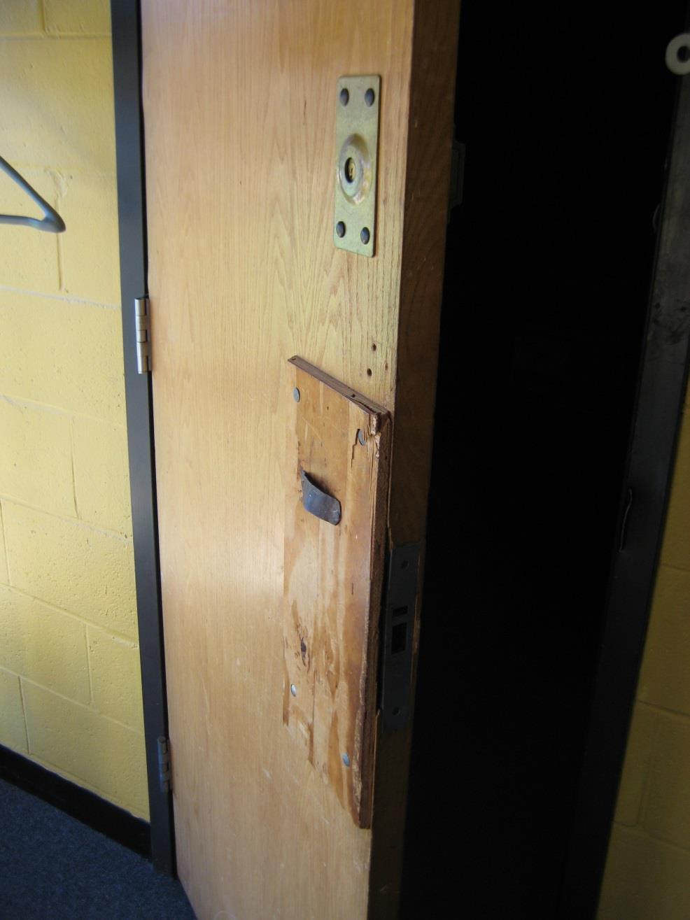
12 Frame jamb extends to floor Fasteners installed in mitres of knock down frames. Free from rust thru area No open holes or breaks in the frame face or door No unused fastener holes
13
14 No holes, cracks, or splits in faces, stiles, and rails of doors No broken welds on rails or stiles of steel doors No holes in faces and edges of steel doors Verify face of door for delaminating of face skins from core of door

15
16 Fill holes with like material or better, ¾ maximum Pre-drill new holes in wood doors Maximum 1 hole can be drilled in doors, except for cylinder Mitre tabs or screws are often missed during construction

17
18 Glazing beads securely fastened Labeled light kits are securely fastened No cracks or chips in glass No missing fasteners No signage, decals, tape, etc attached to glass


19 Correct rating for assembly Correct sized glass 100 square inches for 60 minute and greater doors 1296 square inches for 45 minute and less doors
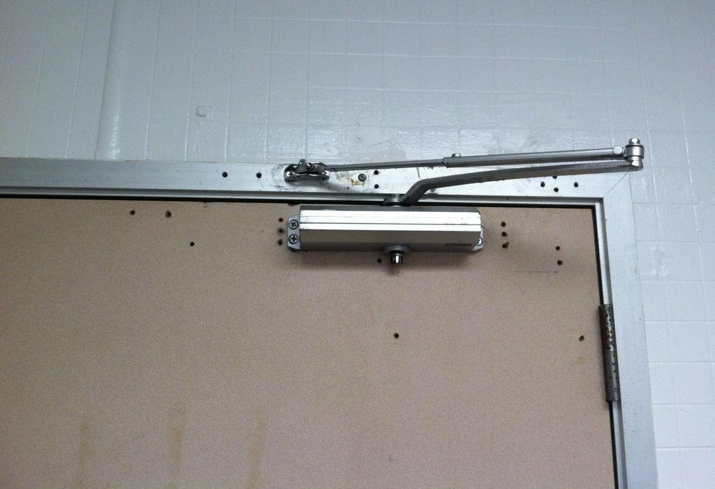
20 Cover label on Lite Kit prior to painting Wire glass is acceptable for rated glass Safety fire rated glass required in locations below 48 on the door. Where the glass is less than 48 above the finished floor on a side lite panel, safety fire rated glass is required
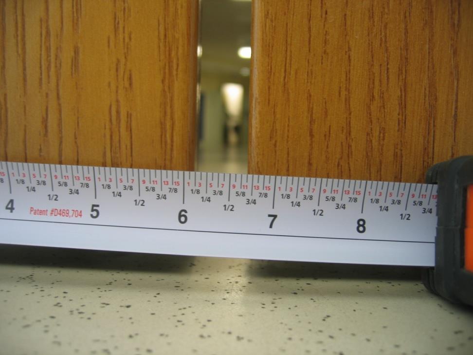
21 At Jambs, Head, & Meeting Stiles Hollow Metal Doors: 1/8 +/- 1/16 Wood Doors: 1/8 Bottom of Door to top of Finished Floor 3/4
22


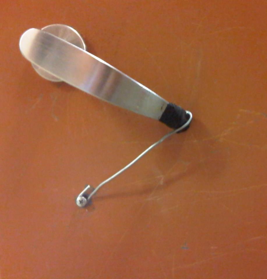
23 Correct operation of doors Swing freely Self-Closing Self-Latching
24 Steel ball-bearing hinges Hinge reinforcements secured to frame. No rust on hinge, screws or reinforcements. No missing, loose or broken screws Ensure continuous hinges are UL rated Hinge pins properly seated
25
26 TIPS Magnet used to determine hinge material Correct screw size is very important Screw hole too big options to correct Add continuous hinge to replace butt hinge Replace hinges can often correct gap issues
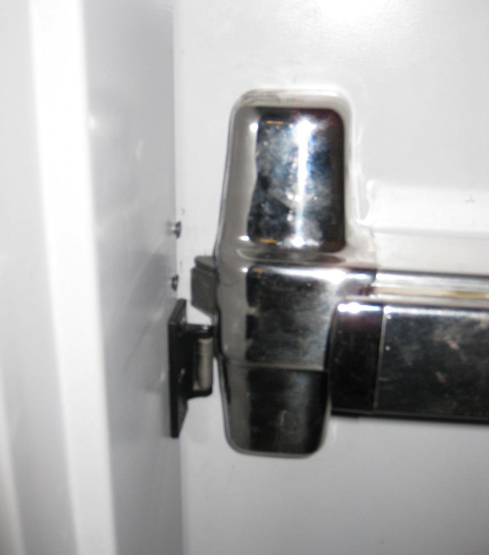
27 Fire labeled or listed Securely attached thru bolted on wood doors No manual hold open Door closes from the full open position (90 degree)
28 Arms properly attached No missing screws Closer not leaking fluid Tips Replace closers with same model or same footprint Adjust closer speed periodically


29
30 Listed or labeled Correctly secured with no broken parts or missing fasteners. Latch projects the required distance into the strike, ½ minimum or as required by the manufacturer
31 Replace hardware with same model or like footprint Latch is usually only indication of UL rating Order doors prepped for hardware

32
33
34 Fire exit hardware label Latch projects the required distance into the strike, ½ minimum or as required by the manufacturer All parts must be installed including lever, knob, end caps, strikes, bottom rods, fire pin Panic hardware is not the same as Fire exit hardware
35 Strikes properly attached, no missing fasteners Confirm that the exit devices are attached to door with thru bolts No dogging of devices exists Less Bottom Rod (LBR) requires fire pin
36
37


38 Manual flush bolts have limited application on fire doors Automatic flush bolts require coordinator and are limited in application as well Be aware of egress requirements (NFPA 101)
39 Used for pairs with an active and inactive leaf To ensure that the inactive leaf closes first Required when automatic flush bolts are used UL labeled or listed


40


41 Must extend ¾ over door edge Astragals shall be full height of doors and securely fastened to door. Cannot be used to close excessive gaps

42 Fire rated or listed Must retract fully and may not rub on floor during opening cycle. Cannot be used to close a gap > ¾ Securely attached to door with no missing fasteners.
43 Plates over 16 in height on fire doors, must be labeled unless allowed by published listings 16 height limit does not apply in Healthcare Maximum mounting height is 48 above finished floor
44 Screws that are drilled for fastening of protection plate must be inserted and properly set Sheet metal fasteners must be used to attach plates No broken screw heads Adhesive application allowed if approved by manufacturer

45
46 Fire rated or listed Continuous around perimeter of door No breaks are allowed Gasket material must be in full contact with door frame All fasteners must be installed
47 NFPA 80 does not specifically address gasket Gasket cannot be used to close excessive gaps Gasket only required under this condition Door label is S endorsed and Wall rating is Smoke or Fire & Smoke rated
48 Attached with adhesive only No nails, screws, tacks, push pins, etc can penetrate door Signage must not exceed 5% of door surface area = % = x15 sign Glazing diminishes surface area Each side can have 5%


49
50 Area around door must remain clear of any materials What to do if door is no longer needed Stairwells cannot be used for storage


51
52
53 PROHIBITED Door wedges Kick Down Stops Stops with Hooks Closers with Hold-Open Arms

54
55

56 Decorations can cause premature door failure due to additional fuel added to fire loading of door.

57 Fasteners penetrate door skin and product adds fuel to fire door assembly.

58 Must activate, as required, upon activation of the following devices Card Readers Key Switches Push Buttons Fire Alarm Activation
59 UL Labeled for Fire Electric Strikes must be fail secure Magnetic Locks do not provide positive latching Best options are electrified mortise or cylindrical levers or electric latch retraction fire exit hardware Not a good option for retrofit

60 Verify gap between electric strike and frame is tight and that screws holding strike, in place are tight.

61 Properly thru-bolted to doors Correct armature installed Chains and other homemade armatures not permitted on fire doors
62 5.5.1 Necessary repairs must be corrected without delay Removal of Door requires opening to be filled to maintain wall rating Upon completion of maintenance work, fire door assemblies shall be inspected and tested Repair of holes in doors and frames use like material Steel shims for shimming to close excessive gaps
63 Damages to Doors and Frames Holes in Doors and Frames Hinges Door Closers Fire Exit Hardware Locksets Electrified Hardware
64
65

66
67

68
69
70
71
72
73


74 QUESTIONS?

75 For your attendance and attention
FIRE RATED DOOR AND FRAME GENERAL REQUIREMENTS
 FIRE RATED DOOR AND FRAME GENERAL REQUIREMENTS These requirements apply to all fire rated doors, frames, and windows. Requirements for the installation of these assemblies are included in the Standard
Infinity 20 Min. FIRE RATED DOORS WARNOCK HERSEY INFINITY - STANDARD RAISED - 20 MIN. RATING SOFTWOOD STILE
 Infinity 20 Min Note: 20 Minute (Positive Pressure) Category A & B Manufacturing Specifications MAXIMUM SIZES All doors shall have a minimum thickness of 1-3/4" + 1/16" Single Swing: 4/0 x 9/0 Standard
Encore 20 Min. FIRE RATED DOORS WARNOCK HERSEY ENCORE - STANDARD PANEL - 20 MIN. RATING
 Encore 20 Min 20 Minute (Positive Pressure) - Category B Manufacturing Specifications MAXIMUM SIZES All doors shall have a minimum thickness of 1-3/4" + 1/16" Single Swing: 4/0 x 8/0 Standard Pair: 8/0
FIRE RATED DOOR AND FRAME GENERAL REQUIREMENTS
 ` FIRE RATED DOOR AND FRAME GENERAL REQUIREMENTS These requirements apply to all fire rated doors, frames, and windows. Requirements for the installation of these assemblies are included in the Standard
Measuring Door Gap Dimensions of Swinging Fire Doors with Builders Hardware
 Recommendations for Measuring Door Gap Dimensions of Swinging Fire Doors with Builders Hardware By Keith E. Pardoe Speed, accuracy, and above all consistency are essential when determining the clearance
For installation assistance, contact SARGENT at DOORS SHOWN HERE SWING IN FOR ILLUSTRATION PURPOSES ONLY.
 SARGENT Installation Instructions for LP8600 x LR8600 & 12-LP8600 x 12-LR8600 Series Low Profile Panic and Fire Exit Devices on Double Egress & Double Doors or LS8600 & 12-LS8600 Low Profile Exit Device
Metal Sound Retardant Door Hardware Information Bulletin
 574 West Otterman Street Greensburg, PA 15601 Toll Free: (800) 979-7300 Local: (724) 834-7300 Fax: (724) 830-2871 Email: overly@overly.com DOOR COMPANY Metal Sound Retardant Door Hardware Information Bulletin
Heavy Wall Applied Stop Tube Frame and Door Installation
 INSTALLATION INSTRUCTIONS Heavy Wall Applied Stop Tube Frame and Door Installation Read all instructions before beginning installation. These instructions are provided to help prevent installation problems
Solid Core Wood Door / Steel Frame Packages
 Solid Core Wood Door / Steel Frame Packages No Label - Interior Packages Machined for one (1) cylindrical lock and three (3) hinges at Republic locations 1-3/4 Solid Core Birch 1-3/4 Solid Core Oak 3/0
DIVISION 8 DOORS AND WINDOWS. 1. Exterior and interior single doors shall be 1-3/4 inch thick, 3 feet wide, and 7 feet high, minimum.
 8.01 DOORS AND FRAMES (12-2-02) A. Doors DIVISION 8 DOORS AND WINDOWS 1. Exterior and interior single doors shall be 1-3/4 inch thick, 3 feet wide, and 7 feet high, minimum. 2. Where required for maintenance
7110(F), 7170(F)(LBR) Surface Vertical Rod Exit Device Series Installation Instructions
, 7170(F)(LBR) Surface Vertical Rod Exit Device Series Installation Instructions") 7110(F), 7170(F)(LBR) Surface Vertical Rod Exit Device Series Installation Instructions Shim (2) Supplied Strike Plate 791 Strike (3) 10-24 x 3/4 (19mm) PFHMS Strike Angle Must Engage Strike 12-24 FHPMS
7110(F), 7170(F)(LBR) Surface Vertical Rod Exit Device Series Installation Instructions Shim (2) Supplied Strike Plate 791 Strike (3) 10-24 x 3/4 (19mm) PFHMS Strike Angle Must Engage Strike 12-24 FHPMS
DOOR SAVERS AVAILABLE IN STEEL, STAINLESS STEEL (32D), BRIGHT BRASS (3), BRONZE (10) AND OIL RUBBED BRONZE (10B)
, BRIGHT BRASS (3), BRONZE (10) AND OIL RUBBED BRONZE (10B)") SAVERS K1 : 9 High For cylindrical locksets 2-1/8 bore, 2-3/8 and 2-3/4 backsets K 188 2-3/8 1-3/8 K 184 2-3/8 1-3/4 K 148 2-3/4 1-3/8 K 144 2-3/4 1-3/4 K5 144 5 SPECIFY K3 : 9 High For cylindrical locksets
SAVERS K1 : 9 High For cylindrical locksets 2-1/8 bore, 2-3/8 and 2-3/4 backsets K 188 2-3/8 1-3/8 K 184 2-3/8 1-3/4 K 148 2-3/4 1-3/8 K 144 2-3/4 1-3/4 K5 144 5 SPECIFY K3 : 9 High For cylindrical locksets
CONCEALED VERTICAL ROD PANIC EXIT DEVICE
 INSTALLATION INSTRUCTIONS CRL JACKSON 1085-1085P CONCEALED VERTICAL ROD PANIC EXIT DEVICE crlaurence.com Phone: (800) 421-6144 Fax: (866) 921-0531 crlaurence.com usalum.com crl-arch.com 11M0236 ORDER OF
4-lite Patio Door. Installation Instructions
 4-lite Patio Door Installation Instructions IMPORTANT: Read the instructions and familiarize yourself with the door parts and pieces before beginning assembly and installation. Note: Only the 5-0 x 6-8
1530(F) Mortise Exit Devices Installation Instructions
 Mortise Exit Devices Installation Instructions") 1530(F) Mortise Exit Devices Installation Instructions Singe Doors or Pairs (2) 12-12-24 PFHUM/WS 798 Universal Strike Standard Device Package Devices are packed ready for application reinforced metal
1530(F) Mortise Exit Devices Installation Instructions Singe Doors or Pairs (2) 12-12-24 PFHUM/WS 798 Universal Strike Standard Device Package Devices are packed ready for application reinforced metal
Exit Device 5820 SERIES GRADE 1 PUSH BAR SPECIFICATIONS HEAD COVER OPTIONS STRIKES APPLICATION.
 Exit Device 5820 SERIES GRADE 1 PUSH BAR 5820F Fire-Rated Mortise Lock Exit Device 5820FSF Failsafe Electric Mortise Exit Device 5820FS Failsecure Electric Mortise Exit Device HEAD COVER OPTIONS HC-1 HC-2
Masonry Frames Interior/Exterior* Drywall Frames Interior**
 Masonry Frames Interior/Exterior* Step your frame: Wire Masonry Anchor Combo Stud Anchor Existing Opening Anchor Hollow Metal 5-3/4" Standard* Frame Includes: 6 gauge - cold rolled steel - primed galvanneal
Safety glasses Measuring tape Level Pencil Power drill Center punch Phillips screw driver Saw horse
 EX76 Concealed Vertical Rod Exit Device Preparation Guide and Installation Instructions Box Contents EX76 Concealed Vertical Rod Exit Device Back Bar Active Push Bar Filler Plate Door Kit with Templates
INSTALLATION INSTRUCTIONS
 INSTALLATION INSTRUCTIONS Thermally Broken Framing and Door Installation SL-450TB (2" x 4-1/2" with 1" Glazing) & SL-600TB (2" x 6" with 1" Glazing) IMPORTANT: Read all instructions before beginning installation.
Finish Hardware. Contents. Section 10
 Section 10 Finish Hardware Contents 10.0.0 Introduction to contents 10.1.0 Door hinges (types and illustrations) 10.2.0 Locksets and latchset configurations and functions 10.3.0 Heavy-duty mortise cases,
* * 22 & 22-F. Please give these instructions to building owner after device is installed BS EN 1125 : 2008
 *911407-00* Rim device 911407-00 22 & 22-F Installation Instructions BS EN 1125 : 2008 Devices covered by these instructions: 22 Rim Exit Device 22-F Rim Fire Exit Device These instructions are presented
Thermally Broken Framing and Door Installation
 INSTALLATION INSTRUCTIONS Thermally Broken Framing and Door Installation IMPORTANT: Read all instructions before beginning installation. These instructions are provided to help prevent installation problems
3-LITE PATIO DOOR INSTALLATION INSTRUCTIONS
 3-LITE PATIO DOOR INSTALLATION INSTRUCTIONS IMPORTANT: Read the instructions and familiarize yourself with the door parts and pieces before beginning assembly and installation. TOOLS NEEDED: Tape Measure
BEFORE STARTING INSTALLATION
 VON DUPRIN Installation Instructions 22 Rim Device Devices covered by these instructions: 22 Rim Device 22-F Fire Exit Rim Device BEFORE STARTING INSTALLATION 1. Check hardware schedule for strikes, fasteners,
INSTALLATION INSTRUCTIONS. Thermal Entrances AA 250/AA 425 THERMAL DOOR WITH TRIFAB 601/601T FRAMING
 JANUARY, 2014 1 INSTALLATION Thermal Entrances AA 250/AA 425 THERMAL DOOR WITH TRIFAB 601/601T FRAMING INSTRUCTIONS 2 FRAME ASSEMBLY JANUARY, 2014 601442 SHEAR BLOCK BALL BEARING NRP BUTT (FACTORY APPLIED
Shim (2) Supplied. Strike Plate. (3) x 5/8" PFHMS or 10 x 1" PFHWS. Top Latch. (3) x 1/4" PRHMS. Latch Cover. (2) 8 x 3/8" PFH AB SMS
 Supplied. Strike Plate. (3) x 5/8 PFHMS or 10 x 1 PFHWS. Top Latch. (3) x 1/4 PRHMS. Latch Cover. (2) 8 x 3/8 PFH AB SMS") Installation Instructions ED5400 (A) Series ED5470 (B) Series Surface Vertical Rod Exit Devices Strike Angle Must Engage Strike Top Strike 10-24 PFHMS Top Bracket and Strike required for ED5470. Shim (2)
Installation Instructions ED5400 (A) Series ED5470 (B) Series Surface Vertical Rod Exit Devices Strike Angle Must Engage Strike Top Strike 10-24 PFHMS Top Bracket and Strike required for ED5470. Shim (2)
series 9500 top load bi4fold installation instructions
 instructions Head Deflection (+0.12 / -0.00 ) Right Jamb Note: This is a top hung product. Provide adequate structure at head. Continuous threshold support is required. Left Jamb Head 4Lay bed of sealant
INSTALLATION INSTRUCTIONS CRL JACKSON
 INSTALLATION INSTRUCTIONS CRL JACKSON 2085 CONCEALED VERTICAL ROD PANIC EXIT DEVICE crlaurence.com Phone: (800) 421-6144 Fax: (866) 921-0531 crlaurence.com usalum.com crl-arch.com 11M0250 ORDER OF ASSEMBLY
7130(F) Series Mortise Exit Devices Installation Instructions
 Series Mortise Exit Devices Installation Instructions") 7130(F) Series Mortise Exit Devices Installation Instructions Outside Trim Device is packed ready for any Yale 650F or 660F Series Trim. End Clamp (3) 8-32 x 5/16" PUFHMS End Cap (2) 1/4-20 x 1" PPHMS
7130(F) Series Mortise Exit Devices Installation Instructions Outside Trim Device is packed ready for any Yale 650F or 660F Series Trim. End Clamp (3) 8-32 x 5/16" PUFHMS End Cap (2) 1/4-20 x 1" PPHMS
ED5800 (A) Series. Installation Instructions. Concealed Vertical Rod. Exit Device WARNING
 Series. Installation Instructions. Concealed Vertical Rod. Exit Device WARNING") Strike Shim (2) Supplied Strike Plate (3) 10-24 x 3/4" PFHMS (6) 10-24 x 1/2" PFHMS Top Latch TopTube Concealed Vertical Rod Exit Device Important: For use with metal doors only. Device is packed ready
Strike Shim (2) Supplied Strike Plate (3) 10-24 x 3/4" PFHMS (6) 10-24 x 1/2" PFHMS Top Latch TopTube Concealed Vertical Rod Exit Device Important: For use with metal doors only. Device is packed ready
PUSH BAR EXIT DEVICES CROSS BAR EXIT DEVICES NARROW STILE EXIT DEVICES FEATURING LCWD STRIKES... 20
 Flat Goods Section TABLE OF CONTENTS EXIT DEVICES PUSH BAR EXIT DEVICES N1500 Heavy Duty Rim Exit Device N1550 Rim Exit Device... 6 N1650 Fire Rated Heavy Duty Exit Device N1700(F) Vertical Rod Heavy Duty
SECTION BULLET- RESISTANT DOORS
 1 SECTION 08 3950 BULLET- RESISTANT DOORS PART 1- GENERAL 1.01 SUMMARY A. This Section Includes: 1. Bullet- resistant steel door and frame systems. 2. Door hardware for bullet- resistant steel door and
7210 Surface Vertical Rod Exit Device Installation Instructions. Outside Trim
 7210 Surface Vertical Rod Exit Device Installation Instructions Top Mounting Plate (2) 1/4-20 x 3/4" PFHMS Blade Stop Block Shim (2 Supplied) Strike Plate 791 Strike (3) 10-24 x 1-1/4" PFHMS Top Latch
Security Inspections are offered at no charge to Bunker Hill, Piney Point, and Hunters Creek residents.
 MEMORIAL VILLAGES POLICE DEPARTMENT 11981 Memorial Drive Houston, Texas 77024 (713) 365-3700 www.mvpdtx.org Serving the cities of Bunker Hill, Piney Point, and Hunters Creek Security Inspections As a resident
INSTALLATION INSTRUCTIONS CRL JACKSON
 INSTALLATION INSTRUCTIONS CRL JACKSON 1285 CONCEALED VERTICAL ROD PANIC EXIT DEVICE crlaurence.com Phone: (800) 421-6144 Fax: (866) 921-0531 crlaurence.com usalum.com crl-arch.com 11M0248 ORDER OF ASSEMBLY
Heavy Wall Applied Stop Tube Frame and Door Installation
 INSTALLATION INSTRUCTIONS Heavy Wall Applied Stop Tube Frame and Door Installation IMPORTANT: Read all instructions before beginning installation. These instructions are provided to help prevent installation
Installation Instructions. 45 and 60-Minute Positive Pressure Fire-Rated Veneered Door Frame UBC & UL-10C
 Wood Doors Installation Instructions 45 and 60-Minute Positive Pressure Fire-Rated Veneered Door Frame UBC 7-2-1997 & UL-10C Positive Pressure Category Requirements: Category C The Maiman Company Fire
Mira Premium Series Bi-Parting French Sliding Patio Door Installation Instructions
 PREMIUM SERIES W I N D O W S Mira Premium Series Bi-Parting French Sliding Recommended Tools & Accessories Tape Measure Level (3 or longer) Hammer Power Screwdriver Load bearing Shims Flashing (recommended)
Fire Door Maintenance Scheme Accepted Repair Techniques
 01 Damage to lipping. If the lipping has splits and gouges where the timber has been broken away, the damaged area should be cleanly cut away by removing the relevant section of timber. A section of hardwood
1510(F) Surface Vertical Rod Exit Devices Installation Instructions
 Surface Vertical Rod Exit Devices Installation Instructions") 1510(F) Surface Vertical Rod Exit Devices Installation Instructions Top Mounting Plate (2) 1/4-20 x 3/4" PFHMS Rod Guide Top Rod Shim (2 Supplied) Strike Plate 791 Strike (3) 10-24 x 3/4" PFHMS or (3)
1510(F) Surface Vertical Rod Exit Devices Installation Instructions Top Mounting Plate (2) 1/4-20 x 3/4" PFHMS Rod Guide Top Rod Shim (2 Supplied) Strike Plate 791 Strike (3) 10-24 x 3/4" PFHMS or (3)
This section describes the design requirements and materials/products for door hardware.
 Facilities Division Standards Section 08710 Door Hardware SUMMARY This section describes the design requirements and materials/products for door hardware. DESIGN REQUIREMENTS Coordinate with the McCarran
Installation Instructions. 45 and 60-Minute Fire-Rated Neutral Pressure Veneered Door Frame UBC & UL-10C
 Installation Instructions 45 and 60-Minute Fire-Rated Neutral Pressure Veneered Door Frame UBC 7-2-1997 & UL-10C Door Requirements: Consult the door manufacturer to make sure that the doors are qualified
ED1300/1300F SERIES CONCEALED VERTICAL ROD DEVICE INSTALLATION INSTRUCTIONS
 ED1300/1300F SERIES CONCEALED VERTICAL ROD DEVICE INSTALLATION INSTRUCTIONS Ver.2 1300 SERIES CONCEALED VERTICAL ROD DEVICE Top Strike Latch Screws Strike Screws Release Plunger Top Latch Plunger Screws
4600 Series Rim Narrow Stile Exit Device Installation Instructions I-ED01162
 DEVICES COVERED IN THIS DOCUMENT: 4600 Series Rim Panic Narrow Stile Exit Device 4600 Series Rim Fire Narrow Stile Exit Device OVERVIEW Outside of Door RHR LHR Inside of Door APPLICATIONS 4950 BLADE STOP
THIS PAGE INTENTIONALLY LEFT BLANK
 THIS PAGE INTENTIONALLY LEFT BLANK Seamed Edge Doors 1000 Series 16 and 18 Gauge Doors Cold Rolled or Galvanized Steel Tight Corner Seam Full Body Polystyrene Core or Honeycomb Core Non-Handed Design 12-Gauge
Installation Instructions ED4400, ED4400M & ED4400MA Series Surface Vertical Rod Exit Devices
 Installation Instructions ED4400, ED4400M & ED4400MA Series Surface Vertical Rod Exit Devices In U.S.: Corbin Russwin, Inc. 225 Episcopal Road Berlin, CT 06037 USA www.corbinrusswin.com In Canada: Door
Please read and understand all instructions before beginning. These instructions cover the non-impact aluminum French Door 101.
 The performance and proper operation of a door is only as good as the installation. By following these instructions, the probability of a good installation greatly increases. Please read and understand
7100(F) series. A conventional exit device for single swing doors or pairs of doors of metal, wood or composite construction.
 series. A conventional exit device for single swing doors or pairs of doors of metal, wood or composite construction.") Page Revised Electronically 12/12 7000 series architectural exit devices introduction Yale 7000 series exit devices deliver an unparalleled combination of durability, breadth of line, innovation and aesthetics.
Page Revised Electronically 12/12 7000 series architectural exit devices introduction Yale 7000 series exit devices deliver an unparalleled combination of durability, breadth of line, innovation and aesthetics.
western series 9500 f loor load The Volume Program window systems westernwindowsystems.com bi fold installation instructions
 series 9500 f loor load bi fold The Volume Program Note: This is a bottom hung product. Provide adequate structure at threshold. Continuous threshold support is required. Right Jamb Head Deflection (+0.12
ED5200S(A) Series ED5200S(A) Series x M107 Windstorm Series SecureBolt Exit Device
 Series ED5200S(A) Series x M107 Windstorm Series SecureBolt Exit Device") ED5200S(A) Series ED5200S(A) Series x M107 Windstorm Series SecureBolt Exit Device Installation Instructions FM532 3/11 (Single Doors or Pairs with Mullion) For Doors of Either Hand In U.S.: Corbin Russwin,
ED5200S(A) Series ED5200S(A) Series x M107 Windstorm Series SecureBolt Exit Device Installation Instructions FM532 3/11 (Single Doors or Pairs with Mullion) For Doors of Either Hand In U.S.: Corbin Russwin,
C-Series & S-Series Classic Frame with Transom (Single or Pair)
") 1. TOOLS REQUIRED Tape measure 6' magnetic level 3' magnetic level Safety Glasses Screw gun #2 Screwdriver tip #3 Screwdriver tip Philips Head screwdriver (Used to move frame on wall using oval slots on
1. TOOLS REQUIRED Tape measure 6' magnetic level 3' magnetic level Safety Glasses Screw gun #2 Screwdriver tip #3 Screwdriver tip Philips Head screwdriver (Used to move frame on wall using oval slots on
STC 46 3-Sided Paired Frame (Double Rabbet Only)
") (Toll Free) Phone 866-452-1845 Fax 910-452-1848 STC 46 3-Sided Paired Frame (Double Rabbet Only) FRAME PART DIMENSIONS E E THROAT THROAT MINIMUM 3 5/16" MAXIMUM 13" D A=Jamb Depth MINIMUM 4 5/16" MAXIMUM
(Toll Free) Phone 866-452-1845 Fax 910-452-1848 STC 46 3-Sided Paired Frame (Double Rabbet Only) FRAME PART DIMENSIONS E E THROAT THROAT MINIMUM 3 5/16" MAXIMUM 13" D A=Jamb Depth MINIMUM 4 5/16" MAXIMUM
INOVO 4-LITE SLIDING PATIO DOOR ASSEMBLY AND INSTALLATION INSTRUCTIONS
 INOVO 4-LITE SLIDING PATIO DOOR ASSEMBLY AND INSTALLATION INSTRUCTIONS IMPORTANT: READ THE INSTRUCTIONS AND FAMILIARIZE YOURSELF WITH THE DOOR PARTS AND PIECES BEFORE BEGINNING ASSEMBLY AND INSTALLATION.
1500(F) Rim Exit Devices Installation Instructions
 Rim Exit Devices Installation Instructions") 1500(F) Rim Exit Devices Installation Instructions Singe Doors or Pairs (Panic Label) 1500 - RHR 1500 - LHR 1500F - RHR (Fire Label) 1500F - LHR Standard Device Package Devices are packed ready for application
1500(F) Rim Exit Devices Installation Instructions Singe Doors or Pairs (Panic Label) 1500 - RHR 1500 - LHR 1500F - RHR (Fire Label) 1500F - LHR Standard Device Package Devices are packed ready for application
Sliding Glass Door Assembly and Installation Guide
 Sliding Glass Door Assembly and Installation Guide Index Door System Components and Hardware The following components are needed to complete the installation of your Sliding Patio Door unit. Check all
Instructions for the installation of Ellison Bronze balanced door models #137 & 138
 1. A packing list will be found in crate No. 1 of each shipment. The parts in the crates should be checked with this list. If there is any discrepancy, notify Ellison Bronze at once. 2. All parts are numbered.
7100(F) series. A conventional exit device for single swing doors or pairs of doors of metal, wood or composite construction.
 series. A conventional exit device for single swing doors or pairs of doors of metal, wood or composite construction.") Page Revised Electronically 12/12 7000 series architectural exit devices introduction Yale 7000 series exit devices deliver an unparalleled combination of durability, breadth of line, innovation and aesthetics.
Page Revised Electronically 12/12 7000 series architectural exit devices introduction Yale 7000 series exit devices deliver an unparalleled combination of durability, breadth of line, innovation and aesthetics.
SECTION FINISH HARDWARE
 SECTION 08710 PART I - GENERAL 1.01 DESCRIPTION A. Scope: Work under this Section shall include all materials and installation necessary to provide Finish Hardware as shown and detailed on the Drawings
3000 Series Exit Devices Premier Product
 00 000 Series Exit Devices Premier Product Certification & Compliance: ANSI/BHMA A56., Grade ANSI A7. Accessibility Code Underwriters Laboratories (UL and CUL) listed for accident hazard (panic) standard.
ED5200(A) Series Rim Exit Devices
 Series Rim Exit Devices") ED5200(A) Series Rim Exit Devices Installation Instructions (Single Doors or Pairs with Mullion) FM156 4/10 (617350602) For Metal, Composite and Wood Doors of Either Hand End Clamp (3) 8-32 x 5/16" Flat
ED5200(A) Series Rim Exit Devices Installation Instructions (Single Doors or Pairs with Mullion) FM156 4/10 (617350602) For Metal, Composite and Wood Doors of Either Hand End Clamp (3) 8-32 x 5/16" Flat
Active Push Bar. Safety glasses Measuring tape Level Pencil Power drill Drill bits: 5/32, 3/4 Center punch Phillips screw driver
 EX88 Interlocking Rim Exit Device Preparation Guide and Installation Instructions Box Contents EX88 Interlocking Rim Exit Device Back Bar Filler Plate Active Push Bar Cylinder and Trim Interface Kit Mounting
INSTALLATION INSTRUCTIONS CRL JACKSON
 INSTALLATION INSTRUCTIONS CRL JACKSON 3185 MID-PANEL CONCEALED VERTICAL ROD PANIC EXIT DEVICE crlaurence.com Phone: (800) 421-6144 Fax: (866) 921-0531 crlaurence.com usalum.com crl-arch.com 11M0252 ORDER
INSTALLATION INSTRUCTIONS FOR ARCHITECTURAL VALUE SERIES ELECTRIC DOGGING / ELECTRIC LATCH RETRACTION AND "H" MODELS (HURRICANE) Endcap P/N:
 Endcap P/N:") 103104 January 20, 2009 INSTALLATION INSTRUCTIONS FOR ARCHITECTURAL VALUE SERIES ELECTRIC DOGGING / ELECTRIC LATCH RETRACTION AND "H" MODELS (HURRICANE) ED Electric Dogging ER ELECTRIC LATCH RETRACTION
103104 January 20, 2009 INSTALLATION INSTRUCTIONS FOR ARCHITECTURAL VALUE SERIES ELECTRIC DOGGING / ELECTRIC LATCH RETRACTION AND "H" MODELS (HURRICANE) ED Electric Dogging ER ELECTRIC LATCH RETRACTION
Atrium Patio Door Field Service Manual
 Atrium Patio Door Field Service Manual December 2005 Table of contents Service Agreement Pg 2 Release Agreement Pg 5 Inspection form Pg 6 Warranty Pg 8 Replacing swing panel Pg 12 Replacing sliding panel
376E Series Exit devices
 376E Series Exit devices The Briton 376E Series is an economical range of push bar devices designed to suit single and double door applications. The 376E Series can be used on aluminium, hollow metal or
Chapter 9. Windows and Exterior Doors
 Chapter 9. Windows and Exterior Doors 9.1 INSTALLING WINDOWS 9.2 INSTALLING EXTERIOR HOUSE DOORS 9.3 INSTALLING SHED DOOR 9.4 INSTALLING EGRESS COMPONENTS Tools needed by volunteers: Hammer Nail apron
World s Leading Manufacturer Of Traffic Doors. Supplemental Instructions for the Single and Double Door Order Form
 World s Leading Manufacturer Of Traffic Doors Supplemental Instructions for the Single and Double Door Order Form World s Leading Manufacturer Of Traffic Doors 2809 SW th Street Redmond, OR 97756 Phone:
.1 Comply with the General Conditions of the Contract, Supplementary General Conditions and the requirements of Division 1.
 PAGE 1 PART 1 GENERAL 1.1 REFERENCE.1 Comply with the General Conditions of the Contract, Supplementary General Conditions and the requirements of Division 1. 1.2 RELATED WORK SPECIFIED ELSEWHERE.1 Installation
EXTRUTECH PLASTICS, INC. Custom Extruder of Close Tolerance Profiles
 PVC SINGLE DOOR INSTALLATION INSTRUCTIONS Single Pre-Hung Doors are shipped assembled in most cases ready for installation. Check the sill; in some cases you may want a sill in this door or if not requested
WOOD AND CLAD COMMERCIAL DOOR WOOD AND CLAD 2 1/4 COMMERCIAL DOOR. Table of Contents
 WOOD AND CLAD COMMERCIAL DOOR WOOD AND CLAD 2 1/4 COMMERCIAL DOOR Table of Contents PAGE History... 2 Part Identification Wood Commercial Door XX RHRA... 3 Part Identification Wood Commercial Door Stationary
98/9927. Devices covered by these instructions: Surface Vertical Rod Exit Device
 911375-00 Surface Vertical Rod Exit Device 98/9927 Installation Instructions Devices covered by these instructions: 98/9927 Surface Vertical Rod Exit Device 98/9927-F (Fire) Surface Vertical Rod Exit Device
Adams rite. Deadbolts, Deadlocks & Hookbolts Series maximum security laminated deadlocks/hookbolts
 1850 Series maximum security laminated deadlocks/hookbolts dams rite Deadbolts, Deadlocks & Hookbolts For single leaf doors where the gap between door and jamb is large ccepts standard mortise cylinder
Entry Mortise Lock Set Lever to Lever
 Entry Mortise Lock Set Lever to Lever 1 Lever 2 Escutcheon 3 Turn Piece 4 Mortise Lock 5 Scalp 6 Mortise Lock Strike 7 Mortise Lock Dust Box 8 Mortise Cylinder 9 Cylinder Swing Cover 10 Spindle 11 Spindle
33/3527A. Devices covered by these instructions: 33/3527A-F (Fire) Surface Vertical Rod Exit Device
 Surface Vertical Rod Exit Device") *911403-00* 911403-00 Surface Vertical Rod Exit Device 33/3527A Installation Instructions Devices covered by these instructions: 33/3527A Surface Vertical Rod Exit Device 33/3527A-F (Fire) Surface Vertical
*911403-00* 911403-00 Surface Vertical Rod Exit Device 33/3527A Installation Instructions Devices covered by these instructions: 33/3527A Surface Vertical Rod Exit Device 33/3527A-F (Fire) Surface Vertical
45 Minute Rated Mineral STC35/34 (FD5-45PP STC 35/34) Bonded Mineral Core, 5-Ply Construction, Cat. A, PP
 Bonded Mineral Core, 5-Ply Construction, Cat. A, PP") 45 Minute Rated Mineral STC35/34 (FD5-45PP STC 35/34) Bonded Mineral Core, 5-Ply Construction, Cat. A, PP (Fire Test Standards IBC, UL-10C, CAN/ULC S104, & NFPA 252) Single Swing (STC35) Pair or Double
45 Minute Rated Mineral STC35/34 (FD5-45PP STC 35/34) Bonded Mineral Core, 5-Ply Construction, Cat. A, PP (Fire Test Standards IBC, UL-10C, CAN/ULC S104, & NFPA 252) Single Swing (STC35) Pair or Double
2300 BI-FOLD INSTALLATION GUIDE
 2300 BI-FOLD INSTALLATION GUIDE INSTALLATION INSTRUCTIONS OF MAIN FRAME Header #8 x 2½ zinc coated screws 2 1 2 Jamb Jamb 1 1 3 #8 x 2½ zinc coated screws 4 1 4 3 #8 x 2½ zinc coated screws 5 Threshold
Ballistic Fiberglass Doors & Frames
 INSTALLATION INSTRUCTIONS Ballistic Fiberglass Doors & Frames IMPORTANT: Read all instructions before beginning installation. These instructions are provided to help prevent installation problems caused
SECTION DOOR HARDWARE
 PART 1 - GENERAL 1.1 DESCRIPTION SECTION 08 71 00 1. Use this section only for NCA projects. 2. Delete between // --- // if not applicable to project. Also delete any other item or paragraph not applicable
Adams Rite. Standard & Heavy Duty Deadlatches Series Heavy Duty Deadlatch
 Standard & Heavy Duty Deadlatches 4900 Series Heavy Duty Deadlatch Function: Flexibility of traffic control and installation is offered by the 4900 Series Deadlatches. A reverse turn of the key while bolt
Ives Pemko Hager 112HD FMSLFHD HD 224HD FMHD HD 210HD FSHD HD 157HD FSCPHD HD
 PART 1 - PRODUCTS 1.1 FASTENERS A. All exposed fasteners shall be Phillips head or as otherwise specified, and shall match the finish of the adjacent hardware. All fasteners ex-posed to the weather shall
Please read and understand all instructions before beginning. These instructions cover impact and non-impact aluminum French Door 650/750.
 The performance and proper operation of a door is only as good as the installation. By following these instructions, the probability of a good installation greatly increases. Please read and understand
Vinyl Sliding Glass Door Assembly Instructions
 Vinyl Sliding Glass Door Assembly Instructions SERIES SGD 5470/5570 Para instrucciones en español, visite: http://bit.ly/pgtassemblyinstructions Parts List ITEM 4 5 6 7 8 9 0 4 5 6 7 8 SGD 5470/5570 PARTS
Chapter 9. Windows and Exterior Doors
 Chapter 9. Windows and Exterior Doors 9.1 INSTALLING WINDOWS 9.2 INSTALLING EXTERIOR HOUSE DOORS 9.3 INSTALLING SHED DOOR 9.4 INSTALLING BASEMENT EGRESS COMPONENTS Tools needed by volunteers: Hammer Nail
TOOLS REQUIRED Metal Wood Wood and Metal Screws. #16 Drill #12-24 Tap. 1/8 Drill
 DEVICES COVERED IN THIS DOCUMENT: 4700S Surface Vertical Rod Device 4700SF Fire Exit Surface Vertical Rod Device TOOLS REQUIRED Metal Wood Wood and Metal Screws Sex Bolts #7 Drill ¼ -20 Tap #16 Drill #12-24
Phone # La Jolla Doors. Block Frame Installation Manual Aluminum Frame with either Vinyl or Aluminum Panels
 Phone # 800-440-8785 www.lajolladoors.com La Jolla Doors Block Frame Installation Manual Aluminum Frame with either Vinyl or Aluminum Panels Thank you for choosing La Jolla Doors In this manual you will
350/500 Heavy Wall TM IR Entrances
 SEPTEMBER, 207 FEATURES Hurricane Resistant Product Blast Mitigation Product Features 50 Heavy Wall TM IR medium stile has vertical stiles, top and 6-/ (65.) bottom rails 500 Heavy Wall TM IR wide stile
Table of Contents Holders & Stops
 Copyright 2003, 2007, 2009-2018, Sargent Manufacturing Company, an ASSA ABLOY Group company. All rights reserved. Table of Contents Overview.... 1 General Information.... 2 Features and Details.... 3 590
8000 SERIES SERIES HEAVY-DUTY MODELS
 GRADE 1 ARCHITECTURAL TYPE EXIT DEVICES 8000 SERIES SERIES HEAVY-DUTY MODELS FEATURES All devices are non-handed design Slight pressure on device touch bar will retract latch(s) for immediate exit Auxiliary
Installing Your Electronic Deadbolt
 Ultra Security Plus Electronic Deadbolt Installation Instructions http://www.hberger.com/video-gallery/electronic-deadbolt New Installation Lock Location Preparation (Skip this section if you door has
OVERVIEW. Mounting Post (2 places) Cylinder Cam. Handing Pin
 Cylinder Cam. Handing Pin") DEVICES COVERED IN THIS DOCUMENT: 46CE Cylinder Escutcheon Key locks and 46DT Dummy Trim Pull when dogged unlocks lever 46BE Blank Escutcheon Always operable 46NL Night Latch Key retracts latchbolt 46NK
DEVICES COVERED IN THIS DOCUMENT: 46CE Cylinder Escutcheon Key locks and 46DT Dummy Trim Pull when dogged unlocks lever 46BE Blank Escutcheon Always operable 46NL Night Latch Key retracts latchbolt 46NK
404 Doors, Doorways, and Gates
 404 Doors, Doorways, and Gates 404.2 Manual Doors, Doorways, and Manual Gates. Manual doors and doorways and manual gates intended for user passage shall comply with 404.2. 404.2.2 Double-Leaf Doors and
Fire Rating 3 hours- hollow metal doors mounted singly 90 minutes- hollow metal and composite core wood fire doors 20 minutes- wood doors
 FM-300 Edge Mount 260 Santa Fe Street, Pomona, CA 91767 800-872-3267 909-632-2300 800-232-6752 fax www.markar.com Heavy-duty 14 Gauge stainless steel US32D Satin Stainless Steel (630) Grade 1 4'0" maximum
Pre-Hanging Information
 Pre-Hanging Information Difference between Door Slab and Pre-hung Door Door Slab Only Door Slab Only No handle preparation. No deadbolt preparation. No frame or hinges included. Pre-hung door Door unit
8/7/ HP SWING DOOR INSTALLATION INSTRUCTIONS
 8/7/17 1200 HP SWING DOOR INSTALLATION INSTRUCTIONS Installation Instructions for Typical Construction These instructions were developed and tested for use with typical construction in a wall system designed
Acoustical Surfaces, Inc.
 RECEIVING 1. Immediately inspect shipment for damage during transit, for example: damage caused by fork lifts, stacking, water stains etc. and disclose to delivery driver prior to signing for receipt.
2. Skid should contain the following: A door & jamb B casing C seal cover kit & D extension jamb set (if ordered), E hardware box.
, E hardware box.") RECEIVING 1. Immediately inspect shipment for damage during transit, for example: damage caused by fork lifts, stacking, water stains etc. and disclose to delivery driver prior to signing for receipt.
RECEIVING 1. Immediately inspect shipment for damage during transit, for example: damage caused by fork lifts, stacking, water stains etc. and disclose to delivery driver prior to signing for receipt.
DCI Hollow Metal Technical Data
 DCI Hollow Metal Technical Data DCI HOLLOW METAL 7980 Redwood Ave Fontana, CA 92336 Phone (909) 770-5700 Toll Free (866) 989-3667 Fax (909) 770-5722 www.dcihollowmetal.com INDEX FRAMES: PAGE # ANCHORS:
1800 Series. Flatbar Exit Devices. An ASSA ABLOY Group brand
 , BC V3L 3B1, BC V3A 8A7, BC V3B 7W3, BC V6G 2M6 1800 Series Flatbar Exit Devices An ASSA ABLOY Group brand , BC V3L 3B1, BC V3A 8A7, BC V3B 7W3, BC V6G 2M6 introduction Yale 1800 series exit devices are
33/3547A. Special tools needed: #10-24 tap Drill bits: #25, 5/16, 13/32, 1/2
 911404-00 Concealed Vertical Rod Exit Device 33/3547A Installation Instructions Devices covered by these instructions: 33/3547A and 33/3548A Concealed Vertical Rod Exit Device 33/3547A-F and 33/3548A-F
Swing Door Installation Manual
 Manual 20D/35D/50D 20DH/35DH 40M/50M 25FD 35XT 50XT 01-4000-03 2010 YKK AP America Inc. is a subsidiary of YKK Corporation of America. TABLE OF CONTENTS Installation Notes.......................................