DELAWARE DIAMOND KNIVES
|
|
|
- Cameron Lamb
- 5 years ago
- Views:
Transcription
1 DELAWARE DIAMOND KNIVES PHASE 4 REPORT December 10, 2010 By Jeff LeBlanc, Nnamdi Ibeka, David Kim, and Matthew Lindemer
2 Table of Contents Updated Project Scope... 3 New Project Information... 3 Prototype Fabrication... 6 Subsystem A: Shaft Collar... 6 Subsystem B: Lead Screws... 6 Subsystem C: Guide Rails... 7 Subsystem D: Digital Indicator and Laser Mount... 7 Subsystem E: Leg Supports... 8 Testing Results & Analysis... 8 Broad Measurement Range (Area)... 8 Broad Measurement Range (Thickness) Measurement Accuracy Assembly Time Mobility Finite Element Analysis Future Process Design Changes Chemical Mechanical Grinding Path Forward Appendix A: Cost Analysis Appendix B: Design Specification Appendix C: Gantt Chart Appendix D: Design Package... 24

3 Updated Project Scope The purpose of this project is to design and manufacture a measuring device that is sensitive enough to precisely measure the thickness of diamond slabs manufactured by Delaware Diamond Knives within an accuracy of 1 micron. The current measurement tools used by Delaware Diamond Knives require the diamond specimens to be removed from their apparatuses which consequently results in measurement inaccuracy due to bow, glue-line thickness, and taper. To combat this issue the new measuring device will be designed to measure the diamond wafers while they remain in their respective positions on the grinding apparatus. New Project Information Since the end of Phase 3, there have been design changes to the grinding arm. The assembled grinding head has been changed from a stationary head to a head that swivels in place. This design has added some difficulty and variables into our Final Concept Design. Since the head of the grinding arm now has the ability to swivel, our Final Concept Design had to attach to the shaft of the head, because the surrounding parts have become moving parts. Also there were new clearance heights around the shaft and the overall dimensions have changed slightly. Updated Design Changes 90 Joining Plate Figure 1: New Rail System Design After our Phase 3 presentation with our sponsor, we found a design flaw in our rail system. The Phase 3 Design Package had assembled our rails using pin connections (connection locations circled in Figure 1). These pin connections would cause our rail system to become a parallelogram over time, because the pin would allow for two degrees of freedom. Our new design uses 90 Joining Plates, which we modeled from any common bridge or truss connection that sustains loading over time. This new connection will provide a more rigid structure and perform better over time than pins would have.
![Knurled Knob Figure 2: Additional Design to Acme Screw Another design change that was made since Phase 3 is the addition of knobs [Figure 2] to the end of our Acme Screws.](/docs-images/85/92943155/images/4-0.jpg "It is difficult to turn the Acme Screws by hand in the prototype, because of the small diameter rod, the grease added to provide extra lubrication to the flange, and the fine thread.")

4 Knurled Knob Figure 2: Additional Design to Acme Screw Another design change that was made since Phase 3 is the addition of knobs [Figure 2] to the end of our Acme Screws. It is difficult to turn the Acme Screws by hand in the prototype, because of the small diameter rod, the grease added to provide extra lubrication to the flange, and the fine thread. The knobs have a knurled radius that provide extra grip when working with the prototype. Another reason why the knobs were knurled is because the employee s at DDK are constantly working with machinery and mechanical devices, so they often have grease on their hands. The knob s will improve our ease of use metric and provide better ability to make fine adjustments. Figure 3: Battery Pack Assembly One of our original metrics from Phase 2 was to use a battery operated laser. However, the manufacturer did not specify if the Voltage to our Laser Level was DC or AC, so we waited till we received the laser before we made our battery pack. The battery back includes 3AA battery in series, which are wired to an operating switch, which allows the operator to turn the laser on and off [Figure 3]. This battery pack improves the mobility metric and the ease of use metric. It improves the mobility metric, because the prototype is no longer limited to operational use near an electrical power source. Also, the ease of use metric is improved, because a switch operated laser will be easier to operate than plugging and unplugging the laser for operational use.

![The design change we decided to make was to use this notched piece of the copper faceplate and extended our reference plane from this point [Figure 5].](/docs-images/85/92943155/images/5-1.jpg "In Phase 3, our design package included a drawing to lathe down the head of the Grinding Arm then insert a plane that would extended in the radial direction beyond the copper faceplate.")


5 Reference Plane Figure 4: New Reference Plane Figure 5: Notched Copper Face Plate During our sponsor discussion after Phase 3, we re-examined any ways to simplify the fabrication process of the reference plane. In inspection of the copper face plates [Figure 4] we found that they were purposely notched to prevent the face plate from rotating in place. The design change we decided to make was to use this notched piece of the copper faceplate and extended our reference plane from this point [Figure 5]. In Phase 3, our design package included a drawing to lathe down the head of the Grinding Arm then insert a plane that would extended in the radial direction beyond the copper faceplate. The new reference plane required less machining, taking advantage of an existing feature, and a smaller amount of material added to the Grinding Head. The smaller amount of material will reduce the risk of changing the performance of the Grinding Head and also improve the metric of ease of use. The shaft collar will be assembled easier with the new reference plane, because it does not restrict some on the clearance problems that occurred with the Phase 3 design. Pinion Rack Set Screw Figure 6: Rack and Pinion Provides Track Movement Figure 7: New Digital Indicator Mount In Phase 3, our design to mount the Digital Indicator to the L-Bracket was done by using the provided hole pattern that was on the back of the Indicator. This design did not allow for any fine adjustments

![This mounting plate also has set screws, seen in [Figure 7] which provides a locking mechanism to ensure that the Indicator does not freely move.](/docs-images/85/92943155/images/6-1.jpg "Prototype Fabrication The main components, including guide rails, acme screws, ball joints, flanges, leveling feet, digital indicator, and laser, were purchased.")
6 because in order to bring the Indicator closer or further away from the diamond film, all the lead screws would have to be adjusted. The new design uses a Rack and Pinion Gear System [Figure 6], where the black knob turns the pinion and translates the motion of the rack, the Indicator, along the distance of the rack. This mounting plate also has set screws, seen in [Figure 7] which provides a locking mechanism to ensure that the Indicator does not freely move. Prototype Fabrication The main components, including guide rails, acme screws, ball joints, flanges, leveling feet, digital indicator, and laser, were purchased. Our design team fabricated the remaining parts. The design was modified in order to simplify machining. All of fabrication and assembly was performed in the Delaware Diamond Knives machine shop. Aluminum sheets were the main fabrication material. The total cost of aluminum stock was $ Subsystem A: Shaft Collar Figure 8: Shaft Collar The Shaft Collar components were milled by a CNC Router, including the hole pattern seen in [Figure 8]. The center arcs in the collar were milled to a radius of 1.35 inches. The three larger holes were milled by the router to a diameter of 0.5 inches, which is the clearance hole size for the flange nuts of the acme screws. The hole pattern around the three holes match the flange hole pattern for the acme screws. These holes were tapped using ¼-20 taper tap then the bottom piece was tapped using 5-40 taps and then deburred. Subsystem B: Lead Screws Most of parts of this subsystem were purchased, but some modification was required. The acme screw was cut using a hack saw to acquire the needed length. Also, since the ball joint thread angle is different from the thread angle of the acme screw, the ball joint threads were bored out with a lathe machine and the acme screws were connected to them using an epoxy. [Figure 9]. Figure9: Lead Screw


7 Subsystem C: Guide Rails Three kinds of brackets used in this assembly, two of the bracket connecting carts and the crossing guide rail, four joining plates, and three brackets connecting the guide rails and ball joints. Two alignment rods were machined on the milling machine for the supporting frame of the rail system. The lip was also fabricated to attach to one of alignment rod. The main caution on this subsystem was keeping the side guide rails parallel to each other. In order to keep the side guide rail parallel, a slip hole feature was machined on the Figure 10: Guide Rail System alignment rods so that the rails could be adjusted on the assembly to make them parallel. After attaching the 90⁰ joining plates with the alignment rods, guide rails were placed on to the opposite side of the joining plates as seen in [Figure 10] using the holes on the guide rails as a clearance hole, punched on the joining plates and tapped using #5-40 taper tap. The cart bracket was tapped with M3 size tap to attach on the carts following the dimensions provided by THK, the guide rail manufacturer. Finally, to mount the crossing guide rail on top of it, the holes were tapped using #5-40 taps. Subsystem D: Digital Indicator and Laser Mount Figure 11: L-bracket with Micrometer and Laser Figure 12: Battery Pack The L-bracket was fabricated to mount digital indicator and laser on opposite sides of each other as seen in [Figure 11]. This bracket was also machined on the milling machine with.125 inch thick aluminum sheet. The battery casing was also modified on the milling machine to allow for the appropriate cavities for both the wires and switch, which increased the overall mobility of the prototype instead of using a power cord. [Figure 12]

![The length of all four threaded rods were modified using a hack saw, as shown in [Figure 13].](/docs-images/85/92943155/images/8-1.jpg "Figure 13: Leg Supports Testing Results & Analysis Broad Measurement Range (Area) Purpose of This Test: The purpose of this test is to prove our measurement area metric.")
8 Subsystem E: Leg Supports Bases of the legs and blocks, which sit on at the end of the rods, were fabricated on the milling machine with aluminum stock, which came from the sponsor s general inventory. The angle at one of corner was cut at 45⁰ to meet the shaft alignment rod lip at its flat surface. The length of all four threaded rods were modified using a hack saw, as shown in [Figure 13]. Figure 13: Leg Supports Testing Results & Analysis Broad Measurement Range (Area) Purpose of This Test: The purpose of this test is to prove our measurement area metric. The metric states that the prototype must have the ability to measure a circular area with the diameter of 50mm or 2 inches. Method: Center the Digital Indicator in the center of the Linear Guide Rail System. Then move the Digital Indicator to the furthest position in the X and Y direction. The Laser Leveling System was not attached beneath the Indicator for this test, but the height and size of the laser was taken into account when taking measurement. All measurements were taken using high accuracy calipers. The measurement was completed by measuring from the outer most radius of the shaft collar to the tip on the Digital Indicator. Since we know that the radius of the Shaft Collar was fabricated with a radius of 1.35inches. So the radius of the Shaft Collar was subtracted from each measurement, which would ensure that we would be taking our measurement from the center of the collar. Figure 14.1: Centering the Digital Indicator within the Rail System


9 Figure 14.2: Indicator to the bottom Y position Figure 4.3: Indicator to the right X position Figure 14.4: Indicator to the left X position Figure14.5: Indicator to the top Y position
10 Test Results: 2.45 (Top Y Position) Y 1.35 Radius (Shaft Collar) 2.55 (Left X Position) X 2.35 (Right X Position) 1.05 (Bottom Y Position) Data Analysis: Every data point measured must be beyond the radius of 25mm or 1 inch, which shows that the Indicator can measure on a diameter of 50 mm or 2 inches. The top Y position, right X position, left X position show that the Indicator satisfies the 50mm requirement and has enough freedom of movement to go farther than the diamond and reach the reference plane. However, the bottom Y position can only reach a radius of 1.05 inches or 27mm, this satisfies the 25mm radius requirement, but does not allow the Indicator to reach the reference plane in the lower Y region of the measuring area. In conclusion, the prototype satisfies the measurement area requirement. In addition to the measurement area requirement, the data taken shows that the reference plane can only be found in the upper Y region of the measuring area because the laser mount below the Indicator allows for less clearance at the bottom position than the top position. Broad Measurement Range (Thickness) Purpose of Test: The purpose of this test is to prove the metric for thickness measurement range of the prototype. The metric states that the prototype must measure a range of 5µm to 2mm. Method: The way this tested was using known thickness values of materials then testing them by first leveling the Indicator. Then providing a measuring surface, aluminum plate, and zeroing the Indicator in this position. Then measuring two materials with known thickness and analyze the results.


11 Figure 15.1: Zeroing Indicator on Aluminum Figure 5.2: Measuring Thin Piece of Paper Figure 16: Gold Colored Diamond Film Figure 17: Measuring Diamond Film Test Results: The first item used for testing was a sheet of paper with a known thickness of 50µm or 0.050mm, this paper was then replaced with a paper of known thickness of 49µm or 0.049mm. This shows that the prototype is able to measure a thickness change of 1µm. Our next item that we measured was a gold diamond film backed by a silicon wafer with the thickness of 3.944mm or 3944µm. This item matches our metric requirement because the film thickness of this silicon wafer is 1.944mm thick and the silicon wafer backing it has a thickness of 2mm. So this wafer represents the maximum testing range for the prototype.


12 Data Analysis: This test shows that the prototype satisfies the thickness range requirement of 5µm to 2mm diamond film. This accuracy can be due to the high tolerance Digital Indicator and also the fine tip that was special ordered from Mahr. This special tip has a diameter of.040 inches or 40 thousands of an inch. However, this small tip also showed how sensitive the Indicator was to small amounts of movement. The combination of the high accuracy Indicator and needle point tip show that operational use of the Indicator will have to be very precise because of the sensitivity. Measurement Accuracy Purpose of Test: The purpose of this test is to prove the metric accuracy of the prototype. The metric states that the prototype must have an accuracy of 1µm. Method: The measurement accuracy and repeatability were tested by taking a displacement measurement from the set reference plane to the top surface of the diamond film wafer each time the prototype was attached to the grinding arm, a total of 12 times. Before taking the measurements specific steps were taken to ensure the measurement readings would be as accurate as possible. Using the three lead screws and the alignment laser, the plane of the prototype was finely adjusted until a parallel was achieved between the plane of prototype and the face of the diamond film. Observing when the center point of the cross-hair laser beam shined directly back into its orifice served as an indicator for when parallel planes were achieved. The results from the measurements are shown in [Table 1] Figure 18: Measuring Data Point Figure 6: Reference Plane with Diamond Film
13 Test Results: Table 1: Displacement Data Trial # Wafer Displacement (mm) MEAN MODE ST. DEV Data Analysis: Based on the data obtained from the measurement trials the measurement prototype was accurate within +/- 5 microns. According to the metric set in the project scope of +/- 1 micron for measurement accuracy, the accuracy of the measurement prototype missed the set metric by 4 microns. Due to this shortcoming an analysis of sources of error were done. After some timely observation the project team identified a few sources of error that could generate such a small discrepancy. Imperfections in part fabrication could be a viable source of error and also vigorous vibrations generated from surrounding machinery also would cause a variance in the accuracy of the prototype. It is also possible that the parallel positioning set during the measurement processes are not always 100% perfect and in that case the accuracy of the device would be offset. Vibrations were considered to be the most underlining cause of in accuracy. Based on these observations the accuracy achieved was deemed acceptable given that it still improves upon the current accuracy of DDK s measuring process. Assembly Time Purpose of Test: The purpose of this test is to test the prototypes assembly time metric. This metric has been adjusted since Phase 2, because of new information gathered about the current process. Currently it takes 15 minutes to remove the wafer, dissolve the adhesive backing, then measure and reapply the


14 wafer to the grinding arm. The target metric is to have the prototype assemble for 12 minutes to outperform the current solution Method: The processing time was tested by measuring time durations during two stages of the diamond film measuring process. The stages observed during the test were the time it takes to attach the measurement device to the grinding arm and the time it takes to disassemble and remove the device from the grinding arm. The test was done in a total 12 trials, each member of the project team completed three trials each. Several people completed multiple time trials in order to generate realistic variances in assembly times, being that many employees at DDK will use the prototype and the assembly and disassembly time will vary from person to person. The data in [Table 2] depicts the recorded times for each of the 12 trials. Figure 20: Assembly the Prototype Figure 7: Prototype Fully Assembled Test Results: Table2: Assembly Data Trial # Mount Time (sec) Dismount Time (sec) Average Time Approx. 4 minutes 7 seconds Approx. 3 minutes 48 seconds


15 Data Analysis: Based upon the information obtained from DDK machinist, Bill Tabeling, the original preparation time needed to get the diamond wafer to be measured was approximately 15 minutes. This process included removing the wafer from the grinding apparatus, soaking it in a solution to soften and dissolve the adhesive, and cleaning the adhesive from the surface completely. Based on the time it originally took to prepare the wafer for measurement, an acceptable goal for set up and breakdown time for assembly time was set at simply achieving a time shorter than the original time it took to prepare the wafer for measurement. As shown in the data table the average set-up and breakdown time for the measurement prototype was approximately 8 minutes, which nearly cuts the time in half from the original preparation time. Based on the given data the assembly time for the prototype is considered acceptable. Mobility Purpose of Test: The purpose of this test is to analyze the mobility metric of the prototype. The metric states that the prototype must weigh less than 5lbs. Method: This test was conducted by weighing the subsystems of the prototype on a packaging scale provided by the sponsor. After all the subsystems have been weighed, the combined weight will be added together. Figure 22: Weighing Indicator Figure 8: Weighting Guide Rails with Acme Screws Test Results: The weight of the prototype in full assembly was measured to be 4.5 pounds. Data Analysis: The components that comprise what is considered to be the full assembly are as follows: shaft collar, acme screws (with nuts and flanges), guide rail assembly with carts, digital indictor with an adjustable mount, alignment laser, a series of brackets used throughout out the assembly, as well as a variety of screws used to assemble the prototype. The leg supports were not include in the weighing process during the mobility testing due to the fact they are handled separately when installing the main measurement device to the grinding arm. As shown by the previously stated results, the weight of the prototype is within the set weight constraints and therefore meets the mobility requirements.


16 Finite Element Analysis Purpose of Test: The purpose of this test is to analyze the durability and the amount of deflection that occurs when the acme screws are loaded differently in potential situations Method: Using SolidWorks and SimulationXpress, a model of the Acme Screw, with the material property of Stainless Steel, was loaded in compression and in a bending moment. Bending Moment on Acme Screw Figure 24: SolidWorks Model of Acme Screw, ¼ inch Diameter, 5 inches Long Figure 25: Fixing Bottom of Screw to Create Screw in Shaft Collar
17 Deflection (mm) Figure 26: Compression Force on top of Screw Simulating Loading from Rails Figure 27: Compression Loading Results from SimulationXpress Table3 Load vs. Max Deflection Load (lbf) Maximum Deflection (mm) E E E E E E E E E E E E E E E E E E E E E E E E E E E E E-04 Chart 1: Acme Screw in Compression Acme Screws in Compression Loading 0.00E Load (lbf) Data Analysis: This testing shows that the screw can be loaded in compression up to 10 lbf, which would be over the realistic loading limit, and still show no significant deflection. The maximum deflections occur in the top of the screw, 8.88x10^-4 mm, where the acme screw would be loaded in compression by the ball joint on the rail system.
 Maximum Deflection (mm) 1.00 2.12E-01 1.50 3.18E-01 2.00 4.24E-01 2.50 5.24E-01 3.00 6.35E-01 3.50 7.41E-01 4.00 8.47E-01 4.50 9.53E-01 5.")
 Data Analysis: The deflection in the screw is the largest at the location of the bending moment.")
18 Deflection (mm) Figure 28: Force Location to Create Bending Moment Figure 29: Resulting Bending Moment of 1 lbf Table 4: Load vs. Deflection Chart 2: Bending Moment on Acme Screw Load (lbf) Maximum Deflection (mm) E E E E E E E E E E E E E E E E E E E E E E E E-01 Bending Moment on Acme Screw 0.00E Bending Moment (lbf) Data Analysis: The deflection in the screw is the largest at the location of the bending moment. The maximum deflection that was seen is 2.12 mm. This is more than expected, but the prototype should never experience a bending moment of 10 lbf. This also shows that the rod is still in the elastic region and has some flexibility. This flexibility will help keep the screw from translating more force into the shaft collar. It is a concern if the acme screw is too flexible because it possibly become permanently deformed.
 Maximum Deflection (mm) 1.00 2.78E-04 1.50 4.17E-04 2.00 5.56E-04 2.50 6.95E-04 3.00 8.33E-04 3.50 9.72E-04 4.00 1.11E-03 4.50 1.25E-03 5.")

19 Maximum Deflection (mm) Bending Moment on Shaft Collar Figure 30: Resultant Deformation Diagram Figure 31: Fixed Shaft Collar Center with Bending Moment Table 5: Load vs. Deflection Load (lbf) Maximum Deflection (mm) E E E E E E E E E E E E E E E E E E E-03 Chart 3: Bending Moment on Shaft Collar Bending Moment on Shaft Collar 3.00E E E E E E E Load (lbf)

20 Data Analysis: This data shows the possible deformation of the Shaft Collar design. The reason why we would want to reduce the deformation in the Shaft Collar is because it could possible move the hole locations. The largest amount of deflection is 2.78E-03 mm, which is not a significant amount of deflection. Therefore, we are convinced under the loading conditions of the prototype there will be no significant deformation causing the prototype to lose any performance metrics. Further Design Development After analyzing the overall design of the measurement prototype there are a few changes that could be made in the future to improve the quality, versatility, and ease of use of the device. In the future DDK will look to upgrade the mounting collar s latching mechanism from screws to toggle clamps. This change will make it easier to fasten the collar to the grinding shaft and will therefore cut down the time it takes to mount and dismount the device to and from the grinding arm substantially. Further feasible design developments also include implementing set screws in the shaft collar which would be used to adjust the diameter of the collar. Such development would make it possible for the measurement device to be adaptable to new grinding mechanisms that DDK will design and fabricate in the future as well as other grinding stations that were not included in the scope of this project. Using set screws would undoubtedly increase the overall adaptability of the prototype. Future Process Design Changes Though fabricating a device that allows one to measure the thickness of diamond wafers while they remain on the grinding arm improves the accuracy and efficiency of the grinding process, it is imperative to recognize that the accuracy in measurement also depends greatly on the efficiency of the grinding process itself. With the implication of that notion, it has been determined that there are more efficient ways to grind CVD diamond films in opposition to the process chosen by Delaware Diamond Knives, such as, Chemical-Mechanical Planarization. Chemical Mechanical Grinding Chemical Mechanical Planarization (CMP) defined as a process of smoothing surfaces by means of both chemical and mechanical forces. This method of surface grinding/finishing can be used to remove topography from silicon oxide, metals, and polysilicon surfaces. The mechanical process currently used by DDK has a much higher surface damage rate when compared to CMP. The process of grinding by method of CMP uses abrasive and corrosive chemical slurry, most likely a colloid, combined with a polishing pad and a retaining ring as shown in [Figure 32]. Also notable, CMP is capable of grinding surface down to Angstrom levels. Figure 32: CMP Diagram:
21 By implementing this grinding process in place of their current fully mechanical grinding process DDK would greatly improve the quality of the diamond films they polish. The faces of the diamond films would definitely be more even and the rate at which films are cracked and damaged during the actual grinding process would decrease greatly. Being that reducing the risk of damage to the diamond film was an essential aspect of the project scope, it would be feasible to propose that DDK look into optimizing their grinding process in the future. Path Forward In order to move our design into a fully working item for all grinding devices a few steps to need be taken. The final design is completed, but to fully implement our design to all of DDK s grinding machines new shaft collars and alignment rods would need to be fabricated to fit grinding machines of different configurations. The manufacturing process is similar to the one used previous. The only differences are the center arc radius of the shaft collar and the distance between the holes that the acme screws come out of. The additional design development as noted previously also includes, toggle clamps and implementing set screws into shaft collar. Finally, the measurement process requires training workers to calculate exact thicknesses from the measured displacement as well as the mounting and dismounting process.
22 Appendix A: Cost Analysis After looking at the materials and parts costs it is determined that a budget of $2000 would be sufficient to complete the prototype. The table below is the complete list of all of parts that were purchased. The two most cost intensive of part were Micrometer and Laser Level. Other purchased products were comparatively small. Some aluminum materials, acme screw handle, and battery pack were provided by Sponsor DDK. The final design cost was about $1,600 which is significantly less than the initial target value of $9,000. Delaware Diamond Knives costs $3,000-$10,000 to grow diamond film on the wafer and have 5% chance of breaking the diamond film while taking on and off from the grinding arm. The use of our design will save at least $1,400 on first month and save same amount money as loss by breaking the diamond film from next month. Over a year, the benefit will be $31,400 at least and $184,000 at most. Purchased Parts: Table6: Purchase Sheet QTY Part Brand Price Quote Order/ Item # (each) 1 Micrometer Mahr XLI $ Mounting Bracket Mahr AT Tip Mahr PT Linear Guide Rail (Cross Section) THK RSR12ZM $ Material Stock McMaster-Carr 9246K13 $ Material Stock McMaster-Carr 8973K43 $ Threaded Rod (Acme) Roton Industries $ Lead Screw Nut Roton Industries $ Lead Screw Flange Roton Industries $ Ball Joint Mid-West Control FMIL250C $ Laser Level Cole-Parmer EW $289 1 Laser Battery Sears UPG 5.00v Lithi $ Leveling Foot 80/20 Inc Rod Ends McMaster-Carr 95475A576 $ Material Stock McMaster-Carr 9135K261 $ Inch Standard Screws McMaster-Carr 91251A080 $ Inch Standard Screws McMaster-Carr 91251A126 $ Inch Standard Screws McMaster-Carr 90128A245 $ Metric Standard Screws McMaster-Carr 91290A113 $ Inch Standard Screws McMaster-Carr 91251A125 $8.44 TOTAL: $1,601.31
23 Future Cost The prototype which was built is only for one type of the grinding machine. The shaft collar and guide rail system including the alignment rod and the corner bracket will be machined for another grinding machine. Also, changes of the laser will increase accuracy of the leveling the system. Table6: Estimated Future Cost Part Price Material Stock $200 Laser $300 Total $500 Appendix B: Design Specification Final Design Details How the Design Works The mathematical theory behind the design is very simple. Our idea for the design was to use a Digital Indicator to measure the change in thickness of the diamond films. Our sponsor gave us a list of assumptions to base our design around. These assumptions include: 1. While the Diamond Film is grown onto the Silicon Wafer during the Chemical Vapor Deposition process in the High Pressure Microwave Plasma Reactor, the Silicon Wafer will not have any thickness etched away and will remain at 1/8 thickness. 2. The current Micrometer at DDK s facility has the ability to map the thickness profile of the Diamond Film after the Diamond is grown onto the Silicon and before the Silicon and Diamond Wafer is placed onto the Grinding Arm. Thus the sponsors current solution with give us an initial thickness profile for the Diamond. 3. The Diamond Film backed with the Silicon Wafer is placed onto the Grinding Arm using a light adhesive. This adhesive is a paste material that is applied by hand, and does not have a uniform thickness profile. Also the lightweight strength of this adhesive cause the diamond to spin in place while it is being grinded because the wheel with physically spin the Diamond and the adhesive does not stop the diamond from rotating. The first things to be done to begin is put the shaft collar over the shaft, and secure the bottom of the collar using ¼-20 screws to pull the collar tight to the shaft. Then level a diamond film measurement is to ensure that the frame of our design and the Digital Indicator is square with the Diamond Film. To do this we will use our laser leveling system, which is backed by the Digital Indicator to ensure we are parallel with the Indicator. Then we will use the three lead screws to make fine adjustments in the angle of the frame. The theory behind this leveling system is that you need three points to create a plane; therefore we need three adjustments to ensure that the digital indicator is on a square plane with the diamond. The purpose of the Digital Indicator is to use the New Surface (which will be added using the lathe), as a reference point that will be permanent. If we directly attach a surface to the shaft of the Grinding Head, we know that it will be an unchanging reference point and square to the diamond.
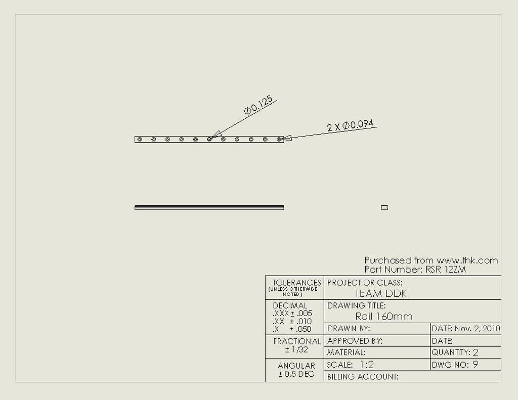
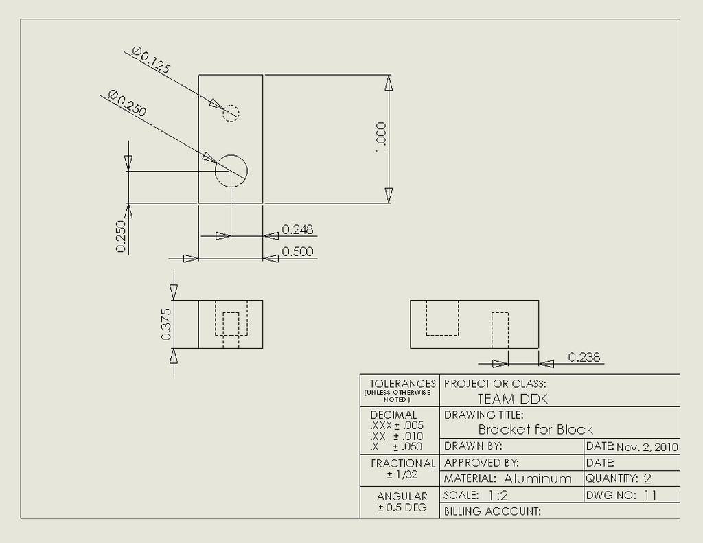
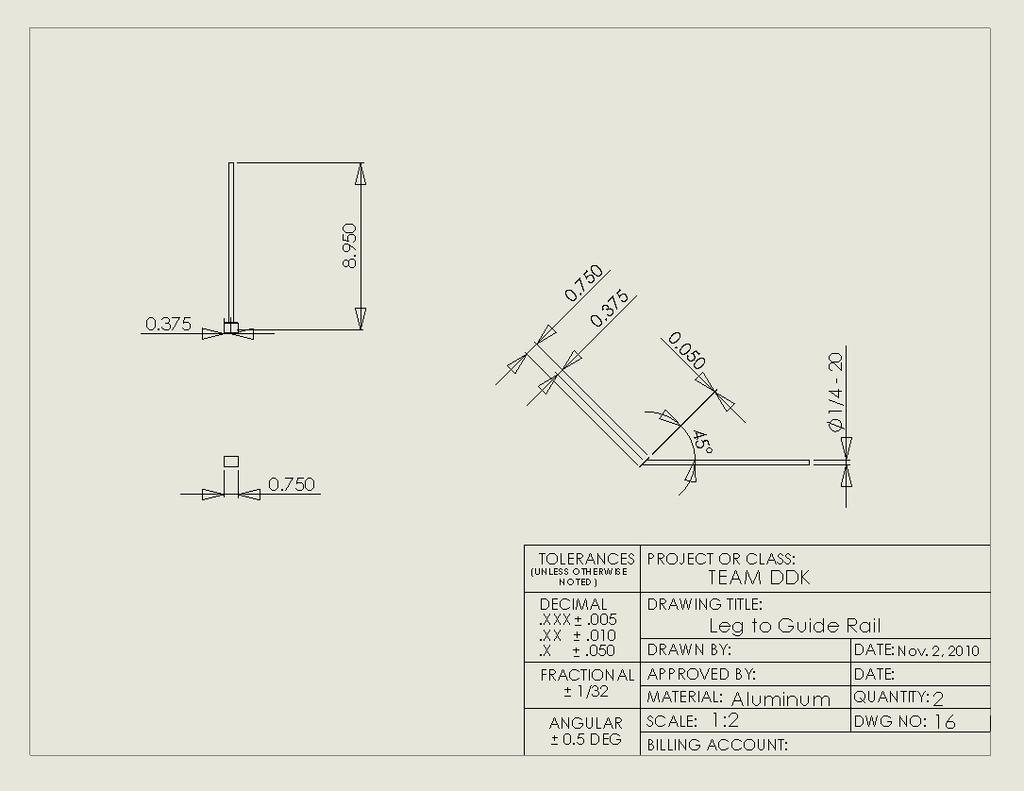
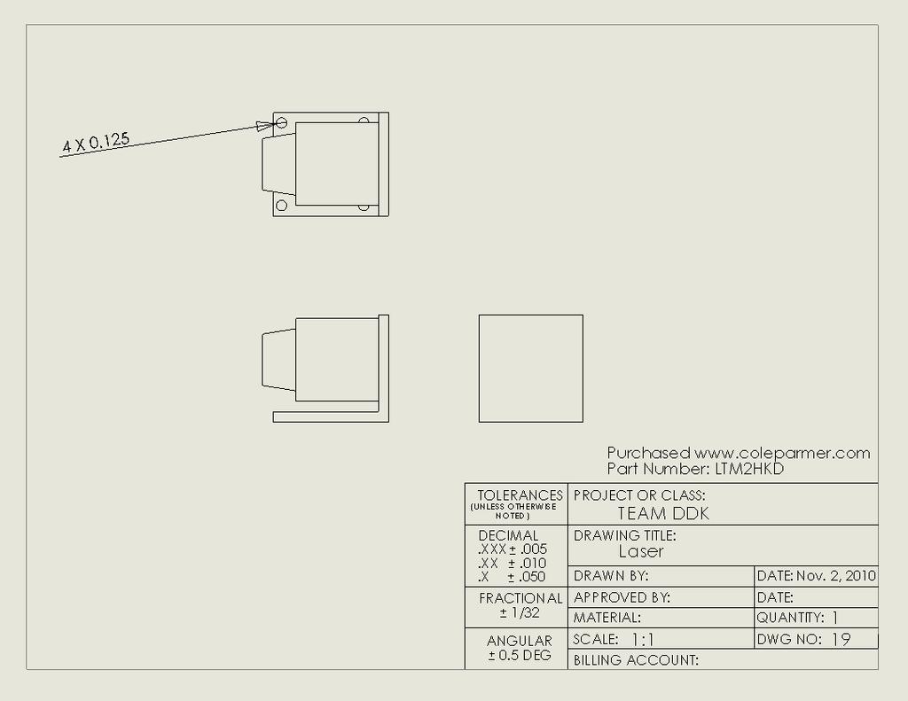
24 The Digital Indicator will measure the distance to the New Surface, and Zero that position. This will be done every time before a measurement is taken. The Digital Indicator will map the height of the diamond film, using the same mapping technique the sponsor uses, and this will be a measurement of the initial height. So after the initial height around the diamond is mapped. The structure will be reattached, leveled, and zeroed. Then the Diamond Film with be mapped again, and the change in height around the Diamond Film will be the resulting thickness change in the Film. Since the initial thickness of the Film is known, we can calculate what the current thickness of the diamond. Appendix C: Gantt Chart The project schedule will be uploaded onto Sakai File Name: Updated Gantt Chart Phase 4_Appendix C Appendix D: Design Package Bill of Materials Table 7: Bill of Materials DWG NO. PART NAME PART NUMBER DESCRIPTION QTY. 1 Lead Screw ¼ -20 Diameter 3 2 Lead Nut Bronze Nut 3 3 Ball Joint FMIL250C ¼ Flange Cart 1 RSR12ZM 3 6 Rail 220mm RSR12ZM 1 7 Alignment Rod 1 8 Alignment Rod with Lip 1 9 Rail 160mm RSR12ZM 2 10 Cart Bracket 2 11 Bracket for Block 2 12 Shaft Collar Shaft Collar Leveling feet 2515T Leg to Collar Shaft 2 16 Leg to Guide Rail 2 17 Base of the Leg 2 18 L-Bracket 1 19 Laser LTM2HKD 1

25 20 Standard Screw 90128A242 ¼ -20 1/2" length 1 21 Standard Screw 91251A173 # /4" length 22 Bracket to Cart 92196A459 # A459, 1/4" Length 23 Standard Screw, 91251A096 # A096 1/2" Length 24 Set Screw 91375A A124 #5-401/4" Length 1 25 Micrometer XLI Digital-1 Stroke 1 Part List Figure 1: Fully Assembled Prototype with Numbers Referencing Bill of Materials in previous page

26 Full Assembly Drawing Figure 2: Assembly Drawing with instructions

27 Sub Assembly Drawings Sub Assembly Drawing #1: Lead Screw Figure 3: Sub Assembly Drawing #1: Lead Screw

28 Sub Assembly Drawing #2: Guide Rail System Figure 4: Sub Assembly Drawing #2 for Guide Rail System

29 Sub Assembly Drawing #3: Collar Shaft

30 Sub Assembly Drawings #4: Support Legs

31 Part Drawings Parts in Sub Assembly #1

32
33

34
35 Parts in Sub Assembly #2

36

37

38
39

40
41

42 Parts in Sub Assembly #3

43

44 Parts in Sub Assembly #4

45
46

47

48 Remaining Parts
49
Guide Pulley System [GPS]
![Guide Pulley System [GPS]](/thumbs/86/93494578.jpg "Guide Pulley System [GPS]") Guide Pulley System [GPS] The purpose of the guide pulley system is to guide the wire from the dancer pulley system to the guide rollers. Two of these systems exist: on both sides of the machine. The pulley
Guide Pulley System [GPS] The purpose of the guide pulley system is to guide the wire from the dancer pulley system to the guide rollers. Two of these systems exist: on both sides of the machine. The pulley
Reversing Gear. Shay Reversing Gear
 Shay Nelson Riedel Nelson@NelsonsLocomotive.com Initial: 9/23/03 Last Revised: 06/05/2004 The reversing gear is another one of those pieces I've been putting off. The reason for the postponement was that
Installation and Leveling Instructions for Micro/Level Wedge Style Isolators
 Technical Bulletin M/L 685 Installation and Leveling Instructions for Micro/Level Wedge Style Isolators 16WL50-1.25M6 with attachment bolt 16WM40-(1)1.25M6 with attachment bolt 12W with Anti-Skid Pad Vibro/Dynamics
Side Winder R o u t e r L i f t.
 Woodpeckers PRECISION WOODWORKING TOOLS Side Winder R o u t e r L i f t. INSTALLATION INSTRUCTIONS The wrench handle must be pointing left in order to fully insert or remove it. Lift Wrench Once fully
Mechanical Frappe Press
 Mechanical Frappe Press Operation Manual CONTENTS OPERATIONAL INSTRUCTIONS PRECAUTIONS PART NAMES INCLUDED ITEMS BASIC OPERATION MAINTENANCE REPLACEMENT PARTS Thank you for using The Frapptastic Five Mechanical
Operating Instructions For Lockformer Button Punch Flanger
 Capacity: 20 to 28 Gauge Galvanize Operating Instructions For Lockformer Button Punch Flanger To satisfactorily form the 90º button punch flange on light gauge materials, it was necessary to form the metal
INSPECTION AND CORRECTION OF BELLHOUSING TO CRANKSHAFT ALIGNMENT
 INSPECTION AND CORRECTION OF BELLHOUSING TO CRANKSHAFT ALIGNMENT BACKGROUND Proper alignment of the transmission input shaft to the crankshaft centerline is required in order to achieve the best results
GAGING AND INSPECTION
 Fixture Plates...75 Fixturing Towers...76 CMM Fixturing Kits... 77-78 Clamping Components... 79-80 Standoffs and Locators... 81-82 Magnetic Components... 83-84 Height Adjustment...84 Positioners...85 Clamp
Budget Robotics Octabot Assembly Instructions
 Budget Robotics Octabot Assembly Instructions The Budget Robotics Octabot kit is a low-cost 7" diameter servo-driven robot base, ready for expansion. Assembly is simple, and takes less than 15 minutes.
Please read these Installation Instructions in their entirety prior to installing or operating this equipment.
 2014-2017 Ram 2500 (All beds) Please read these in their entirety prior to installing or operating this equipment. This hitch is rated to 30,000 lbs. Gross Towing Weight and 7,500 lbs. Tongue Weight Bolt
Agricultural Mechanics and Technology Power Tool Safety Rules
 Agricultural Mechanics and Technology Power Tool Safety Rules Name: BAND SAW Use: Cutting curves, circles and irregular shapes. 1. Use clean SHARP blades. 2. The teeth should always point DOWN. 3. Adjust
Separation Connector. Prototyping Progress Update March 1, 2013
 Separation Connector By Koll Christianson, Luis Herrera, and Zheng Lian Team 19 Prototyping Progress Update March 1, 2013 Submitted towards partial fulfillment of the requirements for Mechanical Engineering
Technicians of Terror. This is the air valve we make to use with our air
 These are pictures of our scissor prop. Technicians of Terror http://www.halloweenfear.com/scissorprop.html props. This is the air valve we make to use with our air This pictures the duel door closer cylinders
Design Guide: CNC Machining VERSION 3.4
 Design Guide: CNC Machining VERSION 3.4 CNC GUIDE V3.4 Table of Contents Overview...3 Tolerances...4 General Tolerances...4 Part Tolerances...5 Size Limitations...6 Milling...6 Lathe...6 Material Selection...7
Travis Bishop. Submitted to: Dr. John Davis. Date: 3 December Course: ETME 310 Section: 004. Lab Topic: Milling Project (Vise)
") Travis Bishop Submitted to: Dr. John Davis Date: 3 December 2012 Course: ETME 310 Section: 004 Lab Topic: Milling Project (Vise) Introduction: Purpose of Experiment: This experiment was conducted to teach
Travis Bishop Submitted to: Dr. John Davis Date: 3 December 2012 Course: ETME 310 Section: 004 Lab Topic: Milling Project (Vise) Introduction: Purpose of Experiment: This experiment was conducted to teach
EllisSaw.com. EllisSaw.com P.O. Box Verona, WI
 P.O. Box 9019 Verona, WI 9-019 GENERAL OPERATING & SAFETY INSTRUCTIONS * READ INSTRUCTIONS BEFORE USE * CAUTION: Disconnect power supply cord from power source when doing repair work or changing belt.
STEEL RULE. Stock TRY SQUARE
 FITTING INTRODUCTION Fitting consists of a handwork involved in fitting together components usually performed at a bench equipped with a vice and hand tools. The matting components have a close relation
Delrin Cone T-Handle Spring Stop w/pad...9 Screw Jack Large Toggle Clamp w/pad...9 Adjustable Ball Positioner...14
 Distributed by Rapp Industrial Sales INDEX Aluminum Fixture Plates...4 Pin Rest...11 Acrylic Plates...4 Thread Adapter...11 Fixturing Towers...5 Delrin Cone...11 CMM Fixturing Kits...6-7 Magnetic Rest
CALIPERS, DIVIDERS AND TRAMMELS
 J.W. DONCHIN CO. 4841-43 W. Chicago Ave. Chicago, IL 60651-3224 Ph: 773-261-2182 Fax: 773-261-2867 Sales@jwdonchin.com www.jwdonchin,com CALIPERS, DIVIDERS 353 Introduction 354 Toolmakers' Spring-Type
AMETAL SHAPER is indispensable for certain METAL SHAPER FOR YOUR SHOP. By S. S. Miner
 METAL SHAPER FOR YOUR SHOP By S. S. Miner AMETAL SHAPER is indispensable for certain machining operations where flat surfaces must be produced within very close limits, such as machining flats on castings,
15 Industrial Tools. Recognized by Professionals. Work Together. Scribing Needle. Replacement of Scribing Needle. Features. Use A B
 Industrial Tools Recognized by Professionals Work Together With battery : Sleeve package Card Box Clear package Scribing Needle 74444 74468 78638 78646 7864 7860 7444 74469 Retracts needle by turning body
Bevels & Gauges. Measuring & Marking T-SLIDE BEVEL PLASTIC HANDLE T-SLIDE BEVEL - ABS HANDLE SLIDING BEVEL INDICATOR BEVEL PROTRACTOR
 T-SLIDE BEVEL - ABS HANDLE For determining existing angles or transferring angles onto a workpiece Slotted hardened steel blade allows the user to accommodate a wide range of different size work pieces
March weeks. surcharge for
 March weeks valid until 31.03.2012 all quoted prices are incl. 19% VAT for deliveries in the EU countries to customers with a valid VAT-no. and for deliveries in not EU member countries the VAT is not
STEINBERGER TRANSTREM (TYPE 2) TECHNICAL DOCUMENT
 TECHNICAL DOCUMENT") STEINBERGER TRANSTREM (TYPE 2) TECHNICAL DOCUMENT These instructions apply to newer style TransTrems only (non-threaded ball type or modified threaded ball type). For purposes of discussion, these TransTrems
STEINBERGER TRANSTREM (TYPE 2) TECHNICAL DOCUMENT These instructions apply to newer style TransTrems only (non-threaded ball type or modified threaded ball type). For purposes of discussion, these TransTrems
Frameless Inline Door With Return QCI5263
 INSTALLATION INSTRUCTIONS Frameless Inline Door With Return QCI5263 WALL MOUNT HINGES FRAMELESS DOOR / PANEL / RETURN PANEL QCI5263 REV. 0 Page 1 Certified 06/17/2016 Parts List with wall mount hinges
c. Pins, bolts, and retaining rings b. Washers, locking nuts, and rivets
 62 20 HW 8: Fasteners / Force, Pressure, Density Mechanical Systems DUE Mon, 11/21/16 Start of class Check link on website for helpful fastener information Please use a scantron. Material is based primarily
STRENGTH Aligned teeth provide superior gripping power over standard vertical teeth. STRENGTH Diamond serrated jaws provide a firm grip
 STRENGTH Aligned teeth provide superior gripping power over standard vertical teeth STRENGTH Diamond serrated jaws provide a firm grip PLIERS AND SNIPS Locking Pliers Slip Joint Pliers Electrician s Pliers
M4 Foot Operated Underpinner Instruction Manual
 M4 Foot Operated Underpinner Instruction Manual M4 Walker Rd, Bardon Hill, Coalville, Leicestershire LE67 1TU, England Tel. +44 (0)130 1692, Fax +44 (0)130 16929 e mail sales@framerscorner.co.uk M4 Underpinner
OPERATION, PARTS & MAINTENANCE MANUAL MODELS HB73-16 HB97-18 HB97-16 HB97-12 HB HB HB HB145-18
 OPERATION, PARTS & MAINTENANCE MANUAL MODELS HB73-16 HB97-18 HB97-16 HB97-12 HB121-18 HB121-16 HB121-14 HB145-18 Proudly Made in the USA 2 3 4 FOREWORD This manual has been prepared for the owner and operators
Laser Guided Rod Wrapper
 Laser Guided Rod Wrapper Operating Manual V 1.2 Quinchat Rods LLC Machines for Makers of Bamboo Rods www.quinchat.webs.com V 1.2 page 1 V 1.2 page 2 Table of Contents 1. Laser Guided Rod Wrapper Features
Tool and Die Maker Level 2
 Level 2 B2 Read and Interpret Drawings II Duration: 32 hours 32 hours 0 hours This unit of instruction introduces the Tool and Die Maker Apprentice with the knowledge and skills necessary to read and interpret
SERVICE PARTS LIST PAGE 1 OF 6 BASE ASSEMBLY SPECIFY CATALOG NO. AND SERIAL NO. WHEN ORDERING PARTS 12" SLIDING COMPOUND MITER SAW
 PAGE 1 OF 6 BASE ASSEMBLY 00 0 CATALOG NO. EXAMPLE: SPECIFY CATALOG NO. AND NO. WHEN ORDERING PARTS 6955-20 1 02-80-0050 Thrust Bearing (1) 2 05-80-0510 M5 x 12mm Flat Head T-20 Screw (5) 3 05-81-0135
ELECTRIC TOOL CORPORATION
 Cat. No. -0 / Hex Demolition Hammer Cat. No. 0-0 Spline Rotary Hammer MILWAUKEE ELECTRIC TOOL CORPORATION W. LISBON ROAD BROOKFIELD, WISCONSIN 00-0 -9-00 d 000 -9-00 d SpecialTools Require Forcing discs
Assembly Instructions 10 X 10 Aluminum Roof Support
 Assembly Instructions 10 X 10 Aluminum Roof Support Aluminum Roof Support Bolt Package 16-5/16 X 2 ¼ SS Bolt 24-5/16 X 1 SS Bolt 40-5/16 SS Nylon Lock Nuts 16-5/16 SS Flat Washers 28-4 ½ Wood Screws 36-1
Mounting the 6 or 12 Indexer on PRS Gantry Tools
 Page 1 Mounting the 6 or 12 Indexer on PRS Gantry Tools About this guide: This document illustrates several options for mounting an indexer onto your ShopBot. You can choose the technique that works best
Note - the nose ribs and are thinner than the main ribs. These nose ribs will use a thinner rib cap than the ribs. This is per design.
 Stabilizer rev 1.2 The SE5a stabilizer is the heartbeat of the tail and is recreated like the full scale version. All tail pieces depend on the stabilizer. It uses the steel fittings, pulleys, inspection
LU6X-130 Instructions and Parts List (including LU6X Basic) Operating Instructions
 Operating Instructions") LORTONE LU6X-130 Item # 061-092 LU6X Basic Item # 061-090 LU6X-130 Instructions and Parts List (including LU6X Basic) Operating Instructions Introduction The LU6X is one the most versatile pieces of equipment
LORTONE LU6X-130 Item # 061-092 LU6X Basic Item # 061-090 LU6X-130 Instructions and Parts List (including LU6X Basic) Operating Instructions Introduction The LU6X is one the most versatile pieces of equipment
Accessories for the Model 920 Lapping and Polishing Machine
 Accessories for the Model 920 Lapping and Machine Applications Laboratory Report Introduction polishing is a common practice in many materials preparation laboratories. Instrumentation for materials processing
SQ2 User Instructions SQ2 Overview:
 SQ2 User Instructions SQ2 Overview: The stationary circular saws including table, radial and chop saws are arguably the most important tools in the shop. They may also be the most difficult to reliably
TENSILKUT ENGINEERING
 TENSILKUT ENGINEERING For Accurate Test Specimens Manufacturer of equipment for the accurate preparation of physical test specimens since 1955 SIEBURG INTERNATIONAL, INC. 1901 Clydesdale Street, Maryville,
FLIP TARP SINGLE & DOUBLE UNDERBODY TRAILERS
 1-800-248-7717 1002 N. 15th Street, Middlesboro, KY 40965 FLIP TARP SINGLE & DOUBLE UNDERBODY TRAILERS INSTALLATION INSTRUCTIONS Congratulations on your purchase of a Mountain Flip Tarp Trailer system.
Mobile Weapons Storage System Specifications
 Mobile Weapons Storage System Specifications Whatever your weapon storage needs, Hi-Density s customized Weapons Storage System will be designed to fit your unique specifications. We recognize that security
1964 ½ Mustang Front Suspension Installation Instructions
 1964 ½ - 1970 Mustang Front Suspension Installation Instructions 1-800-984-6259 www.totalcostinvolved.com All engine installations with this front end will require a rear sump oil pan. 289-302 Small Block
Quick-Release Front Vise 05G34.01
 Quick-Release Front Vise 05G34.01 Patent Pending Introduction A front vise is the most generally useful vise on a typical workbench. It can be used for clamping parts on edge within the jaws, for clamping
ELECRAFT KXPD1 PLUG-IN KEYER PADDLE
 Introduction ELECRAFT KXPD1 PLUG-IN KEYER PADDLE Assembly and Operating Instructions Revision B, July 27, 2011. Copyright 2011, Elecraft; All Rights Reserved The KXPD1 is a unique plug-in keyer paddle
ROOP LAL Unit-6 Lathe (Turning) Mechanical Engineering Department
 Mechanical Engineering Department") Notes: Lathe (Turning) Basic Mechanical Engineering (Part B) 1 Introduction: In previous Lecture 2, we have seen that with the help of forging and casting processes, we can manufacture machine parts of
Notes: Lathe (Turning) Basic Mechanical Engineering (Part B) 1 Introduction: In previous Lecture 2, we have seen that with the help of forging and casting processes, we can manufacture machine parts of
7x --Tailstock Cam Lock
 7x --Tailstock Cam Lock By Magic Brian magicbrian40@yahoo.com Probably the most pleasing mod to have, but often not done through lack of milling facility s This version does NOT require a mill. MATERIALS
Equipment can t stand in the way of striving for perfection Equipment should help to achieve it
 Equipment can t stand in the way of striving for perfection Equipment should help to achieve it CZARCIE KOPYTO NEW GENERATION OF DRUM PEDAL designed and produced in Poland State-of-the-art equipment, setting
Introduction to Manufacturing Processes
 Introduction to Manufacturing Processes Products and Manufacturing Product Creation Cycle Design Material Selection Process Selection Manufacture Inspection Feedback Typical product cost breakdown Manufacturing
Sheet Metal Tools. by:prem Mahendranathan
 Sheet Metal Tools by: SHEET METAL TOOL KIT SHEET METAL TOOLS Rivet Gun 3/32, 1/8, 5/32, 3/16",Cupped Set Mini Bucking Bar Footed Heel-Toe Bucking Bar Air Tool Oil Mechanics Tool Bag High-Speed Air Drill
USE THE PARTS LIST BELOW TO MAKE SURE YOUR KIT IS COMPLETE BEFORE INSTALLATION. IF ANY PIECES ARE MISSING, PLEASE CONTACT:
 1967-1969 Cougar Custom IFS Install Sheet Tech Line: 1-855-693-1259 www.totalcostinvolved.com Read and understand these instructions before starting any work! USE THE PARTS LIST BELOW TO MAKE SURE YOUR
Pivot-Door Downdraft Cabinet Plans
 Pivot-Door Downdraft Cabinet Plans Finished Cabinet Closed Open Exploded View Introduction This simple downdraft-style dust collection cabinet is a great way to keep your shop cleaner and keep your router
SERVICE PARTS LIST PAGE 1 OF 6 BASE ASSEMBLY SPECIFY CATALOG NO. AND SERIAL NO. WHEN ORDERING PARTS 12" DUAL BEVEL COMPOUND MITER SAW B27B
 PAGE 1 OF 6 BASE ASSEMBLY 00 0 EXAMPLE: Component Parts (Small #) Are Included When Ordering The Assembly (Large #). SPECIFY CATALOG NO. AND NO. WHEN ORDERING PARTS = Part number change from previous service
Tools: Sharpie, Square, Vise, Hack saw, Ruler, Punch, Hammer, File. 2. Cut the stock Place stock in vise and cut with hack saw
 Purpose: MAKE CATAPULT ARM Step 1 Tools: Sharpie, Square, Vise, Hack saw, Ruler, Punch, Hammer, File Materials: Flat aluminum ½ inch stock (see picture below) Gloves required 1. Pick up the aluminum ½
Cross Peen Hammer. Introduction. Lesson Objectives. Assumptions
 Introduction In this activity plan students will develop various machining and metalworking skills by building a two-piece steel hammer. This project will introduce basic operations for initial familiarization
REPAIR INSTRUCTIONS. Cat. No Cat. No MILWAUKEE ELECTRIC TOOL CORPORATION. SDS Max Demolition Hammer. SDS Max Rotary Hammer
 Cat. No. 9-0 SDS Max Demolition Hammer Cat. No. -0 SDS Max Rotary Hammer MILWAUKEE ELECTRIC TOOL CORPORATION W. LISBON ROAD BROOKFIELD, WISCONSIN 00-0 8-9-0 d 000 8-9-0 d Special Tools Require Forcing
INSTALLATION INSTRUCTIONS CHEVY C-10 INDEPENDENT FRONT SUSPENSION
 INSTALLATION INSTRUCTIONS 73-87 CHEVY C-10 INDEPENDENT FRONT SUSPENSION Please read these instructions completely before starting your installation. Assemble suspension on vehicle before powder-coating
MSR/MSB Mechanical Setting Tool
 Tech Unit No: 0620000004 Revision: B Approved By: Quality Engineer Date: 2014-12-16 MSR/MSB Mechanical Setting Tool FEATURES: Special designed Bow Spring provides positive control and allows one size Mechanical
Tel / (USA & CANADA) /
 /") Tel.58.847 / 8.388.459 (USA & CANADA) / Email sales@msdiscounttool.com MULTIPURPOSE CLAMPS - USA SERIES 7: Lightweight and 4% stronger than C clamps. Floating jaws that always stay parallel. Designed to
Tel.58.847 / 8.388.459 (USA & CANADA) / Email sales@msdiscounttool.com MULTIPURPOSE CLAMPS - USA SERIES 7: Lightweight and 4% stronger than C clamps. Floating jaws that always stay parallel. Designed to
Horizontal Cable Systems
 ALUMINUM RAILING INSTALLATION INSTRUCTIONS v2012 orizontal Cable Systems 1) Check Contents Of Packages: Verify that all parts have arrived and that they match the packing list. 1A) Coastal applications:
5.Use Spray gasket glue or Silicone Sealant on 1214 Valve Plate. When tacky, place on motor block with 1225 timing plate towards front.
 Assembly 2000 1.Press on 1241S Counterweight Guards onto 1215 Motor Block. The end with the hole goes towards the center. Note slot on top of 1215 Block always goes towards the front. Put 1212S Rings on
A Reference Guide. Continuous Hinge, Inventory and Service Worldwide Est End Play Design Engineering with Standard Continuous Hinges
 Hinge Width Paint Clearance Knuckle Length End Play Design Engineering with Standard Continuous Hinges A Reference Guide Knuckle Dear Design Engineer or Purchasing Agent, We frequently see blueprints for
MODEL T28173/T28174 ROLLER TABLES INSTRUCTIONS
 MODEL T28173/T28174 ROLLER TABLES INSTRUCTIONS FOR MODELS MFD. SINCE 10/17 For questions or help with this product contact Tech Support at (570) 546-9663 or techsupport@grizzly.com Rails Rollers Reversible
SPIDA SAW OPERATIONS MANUAL
 SPIDA SAW OPERATIONS MANUAL CM SERIAL NUMBER. OCTOBER 2000 CONTENTS Page description 1.) Contents 2.) Safety First 3.) CM Overview 4.) CM Specifications 5.) CM Installation 6.) CM Operation Setting the
Pow-R-Feed Systems Service Manual
 Pow-R-Feed Systems Service Manual Important Safety Instructions Please read this manual carefully and follow its instructions. Improper use or failure to follow these instructions could result in serious
ACCREDITATION FACILITY AUDIT CHECKLIST
 ACCREDITATION FACILITY AUDIT CHECKLIST Institution Name: Date: Designated Trade: Machinist AC #: Contact: Location: Course Duration: of weeks: of hours total: of hours per day: Instructor(s) of Students
Victor Figueroa. Bachelor of Science. at the. September Victor Figueroa All Rights Reserved
 Designing a Mechanism to Cleave Silicon Wafers by Victor Figueroa Submitted to the Department of Mechanical Engineering in partial fulfillment of the Requirements for the Degree of Bachelor of Science
Precision made in Germany. As per DIN The heart of a system, versatile and expandable.
 1 Precision made in Germany. As per DIN 8606. The heart of a system, versatile and expandable. Main switch with auto-start protection and emergency off. Precision lathe chuck as per DIN 6386 (Ø 100mm).
IIHS Side Impact Outrigger
 IIHS Side Impact Outrigger Assembly Procedure Base Assembly (14.3 lbs) The base assembly consists of a ¼ thick steel plate, a ¼ thick piece of polyethylene, and mounting fixtures for the upper and lower
TIPS FOR CHOOSING A PROTOTYPING MACHINE SHOP
 CHOOSING the right prototyping machine shop for your next project is quite possibly the most important decision you will make in the entire process. This is particularly true for entrepreneurs with little
MOVENTO. The Evolution of Motion
 The Evolution of Motion is the latest advancement in concealed runner technology. It brings together all of the features, innovations and benefits that Blum has developed since first manufacturing drawer
Catalog October Speedi-Sleeve The quickest and most economical way to repair worn shafts
 Catalog 457027 October 2005 Speedi-Sleeve The quickest and most economical way to repair worn shafts Table of Contents The Speedi-Sleeve concept...3 SPEEDI-SLEEVE, the quickest and most sensible way to
General Four-Way Operation, Maintenance & Service Manual
 General Four-Way Operation, Maintenance & Service Manual SCOPE Included in the following pages you will find assembly drawings, exploded views, parts lists, assembly tips, operational descriptions and
MINI-LATHE QUICK CHANGE TOOL POST
 MINI-LATHE QUICK CHANGE TOOL POST Cutting and assembly details Machinists should familiarize themselves with the contents of this section before jumping in to the drawings. Many details are described here
1/2/2016. Lecture Slides. Screws, Fasteners, and the Design of Nonpermanent Joints. Reasons for Non-permanent Fasteners
 Lecture Slides Screws, Fasteners, and the Design of Nonpermanent Joints Reasons for Non-permanent Fasteners Field assembly Disassembly Maintenance Adjustment 1 Introduction There are two distinct uses
no mm no Dividers with scriber 150 mm NEW Square wedge-shaped knife edges on the length side
 Summer Promotion valid until 30.06.2013 all quoted prices are incl. VAT for deliveries to EU countries to customers with valid VAT-no. and for deliveries in non EU member countries the VAT is not applicable
VERSAtoolTM SAE J533 & SAE J1453. Safety and Operating Manual
 VERSAtoolTM Mechanically Assisted / Manual Tube End Flare & Flange Machine SAE J533 & SAE J1453 Safety and Operating Manual I. Safety Instructions................................. Page 2 II. Specifications.....................................
ASSIGNMENT 4. Textbook Assignment: The point, edge, face, heel, and tang are the five parts of which of the following tools?
 ASSIGNMENT 4 Textbook Assignment: "Files," "Grinders and Sharpening Stones," "Scrapers," "Awls," "Bolt and Cable Cutters," "Glass Cutters," "Knives,' 'Pipe Cutting and Threading Tools," "Tube Cutting and
Tool School - Rotary Draw Bending Tooling. An Engineer s Guide to Bending Tubes
 Tool School - Rotary Draw Bending Tooling An Engineer s Guide to Bending Tubes Tube Form Solutions Tool School Rotary Draw Bending Tooling Tool School Agenda: Introduction To Rotary Draw Bending Engineering
Procedure for Longworth Chuck construction
 Procedure for Longworth Chuck construction Overall construction The Longworth chuck is composed of three major components. Connected to the lathe spindle is some device that fastens to the first of two
AK846 Sander/Planer Kit and AK845 GRS Adapter Instruction Handbook
 AK846 Sander/Planer Kit and AK845 GRS Adapter Instruction Handbook The Foredom Electric Company 16 Stony Hill Road, Bethel, CT 06801 203-792-8622 fax: 203-796-7861 www.foredom.com FOREDOM Sander/Planer
HANDRAIL HEIGHT PER LOCAL CODE AUTORITY
 WITH WOOD END CAPS PLEASE READ PLEASE READ THESE INSTRUCTIONS THOROUGHLY PRIOR TO BEGINNING THE INSTALLATION! 3" [77.3mm] THIS INSTRUCTION SHEET IS INTENDED TO PROVIDE A SPECIFIC GUIDE TO FOLLOW FOR THE
CHAPTER 8. Through Dovetail Procedures
 CHAPTER Through Dovetail Procedures 52 Chapter D4 User Guide THROUGH DOVETAIL PROCEDURES Chapter Foreword In these instructions for using the Leigh Dovetail Jig, we have recommended using certain cutters
Machining. Module 6: Lathe Setup and Operations. (Part 2) Curriculum Development Unit PREPARED BY. August 2013
 Curriculum Development Unit PREPARED BY. August 2013") Machining Module 6: Lathe Setup and Operations (Part 2) PREPARED BY Curriculum Development Unit August 2013 Applied Technology High Schools, 2013 Module 6: Lathe Setup and Operations (Part 2) Module Objectives
Machining Module 6: Lathe Setup and Operations (Part 2) PREPARED BY Curriculum Development Unit August 2013 Applied Technology High Schools, 2013 Module 6: Lathe Setup and Operations (Part 2) Module Objectives
INSTALLING YOUR NEW SPRING LIFT ARM KIT
 INSTALLING YOUR NEW SPRING LIFT ARM KIT 1. Measure the distance that the roof is to be raised. [If your lift system is completely non-functional, you will need to calculate or estimate this distance as
INTRODUCTION. EqunioxRoof.com. Pro Tip
 INSTALLATION MANUAL INTRODUCTION The Equinox Louvered Roof System is designed to be installed in an aluminum frame. All these sections are 1/8" thick extruded aluminum. All engineering for this system
INSTALLATION OF WELLS SUPER QUICK CHUCK LEFT HAND ON RED WING LATHE
 DENTAL, INC. TECHNICAL BULLETIN Q824-022510 5860 FLYNN CREEK ROAD READ ALL INSTRUCTIONS P.O. BOX 106 BEFORE PROCEEDING COMPTCHE, CALIFORNIA, U.S.A. 95427 SAVE THIS FOR FUTURE REFERENCE www.wellsdental.com
TOOL LIST FOR TAILGATE HIDDEN LATCH & LINK ASSY FOR FORD FLARESIDE TRUCKS
 TOOL LIST FOR TAILGATE HIDDEN LATCH & LINK ASSY FOR 53-87 FORD FLARESIDE TRUCKS Vise Grip Clamps C-clamps Sharpie Marker Ball Peen Hammer Center Punch 3/8 or 1/2 Drill 5/32, 7/32, 9/32, and 3/8 Drill Bits
Lathe Accessories. Work-holding, -supporting, and driving devices
 46-1 Lathe Accessories Divided into two categories Work-holding, -supporting, and driving devices Lathe centers, chucks, faceplates Mandrels, steady and follower rests Lathe dogs, drive plates Cutting-tool-holding
Kwik-Lock. Installation Instructions. Attention Dealers: Please give this owners manual to the customer when the product is delivered.
 Serving the Truck & Trailer Industry Since 1944 Installation Instructions Attention Dealers: Please give this owners manual to the customer when the product is delivered. Call 800-535-9545 www.aeroindustries.com
Name: Machine Tool Technology ( )
") Name: Machine Tool Technology (58.0501) Directions: Evaluate the student by checking the appropriate number to indicate the degree of competency. Rating Scale (0-6): 0 No Exposure no experience/knowledge
Name: Machine Tool Technology (58.0501) Directions: Evaluate the student by checking the appropriate number to indicate the degree of competency. Rating Scale (0-6): 0 No Exposure no experience/knowledge
Assembly & Construction Procedures
 Assembly & Construction Procedures Foreword: This device was designed as an open source open architecture technology. With that in mind the construction of this device was made to be extremely flexible.
Model-Maker s Milling Assembly Instructions
 AllSet Milling with body attachment components. Congratulations on your purchase of the AllSet Model-Maker s Milling Assembly Kit. Put your AllSet guide to work for you and see how it can reduce your work
Student, Department of Mechanical Engineering, Knowledge Institute of Technology, Salem, Tamilnadu (1,3)
") International Journal of Scientific & Engineering Research, Volume 7, Issue 5, May-2016 11 Combined Drilling and Tapping Machine by using Cone Mechanism N.VENKATESH 1, G.THULASIMANI 2, S.NAVEENKUMAR 3,
International Journal of Scientific & Engineering Research, Volume 7, Issue 5, May-2016 11 Combined Drilling and Tapping Machine by using Cone Mechanism N.VENKATESH 1, G.THULASIMANI 2, S.NAVEENKUMAR 3,
Fairlane Front Suspension Install Sheet
 1966-1967 Fairlane Front Suspension Install Sheet 1-866-925-1101 Read and understand these instructions before starting any work! 1966-1967 Fairlane Front Suspension Installation Instructions Thank you
COMMON WRENCHES INTRODUCTION
 COMMON WRENCHES INTRODUCTION A wrench is a hand tool used to provide grip and mechanical advantage in applying torque to turn objects usually nuts and bolts. Wrenches allow us to use less force to rotate
DYNATRAC BALL JOINT REBUILD INSTRUCTIONS V4.0
 DYNATRAC PRODUCTS 2007-2016 4X4 JEEP JK HEAVY DUTY BALL JOINT JP44-2X3050-C DYNATRAC BALL JOINT REBUILD INSTRUCTIONS V4.0 WARNING: Improper use or installation of this product can cause major failures
Gared Pro-S Portable Backstop
 Models: 9616 & 9618 Installation, Operation and Maintenance Instructions Please read all instructions before attempting installation or operation of these units SAVE THESE INSTRUCTIONS FOR FUTURE USE PUBLICATION
STAR TOOL SUPPLY / GRAND TOOL SUPPLY
 MULTIPURPOSE CLAMPS - USA SERIES 7: Lightweight and 4% stronger than C clamps. Floating jaws that always stay parallel. Designed to eliminate distorting or twisting action. Cantilever action provides 4:
installation guide 1 GUIDE#: pwb-assault-004
 assault WAKEBOARD tower installation guide INSTALLATION SUPPORT 1 important information This Aerial wakeboard tower fits motor boats with 76-108 inch wide beam widths. This measurement is taken from the