Plastibeton Trench System. Installation Packet
|
|
|
- Alfred Neal
- 5 years ago
- Views:
Transcription

1 Plastibeton Trench System Installation Packet
2 Plastibeton Installation Guide This Installation Guide is intended to assist in the preparation and installation of Plastibeton products manufactured by Oldcastle Infrastructure. The Plastibeton technology and design are proprietary to Oldcastle Infrastructure and this installation manual should not be used for any other products. Your project will have a layout and plans supplied by Oldcastle Infrastructure which shall be referred to while using this Installation Manual. Any questions regarding installation of this product should be directed to a Plastibeton technical support member at Contents Preparation and Setup Equipment Required Offloading and Storage Trench Excavation Bed Preparation Leveling Geotextile Fabric Handling and Installation Harness Connection Eye Bolt Configuration Lifting and Placement Setting the Channels Aligning and Connecting Channel Sections Finish Details Backfilling Cover Supports Installing Cover Supports Protection Rods and Covers Proper Cover Installation Additional Trench Protection Cover Cut Parameters All Covers - General Requirements Cover Model C6 Cover Model C12 and C20 Cover Model C30 Cover Model C Oldcastle, Inc. Page 2
3 Trench Body Cut Parameters All Trenches - General Requirements All Trenches - Door Cuts All Trenches - Angle Cuts All Trenches - Vertical Deviation Trench Model 68 Trench Model 128 and 1216 Trench Model 2012 and 2016 Trench Model 3012 and 3016 Trench Model 4016 Field Drilling End Plate Installation Fire Stop Installation Oldcastle, Inc. Page 3


4 Preparation and Setup Equipment Required Back Hoe Nylon Slings with Hooks Shovels Offloading and Storage Tape Measure 16 /100 Wrecking Bar Sledge Hammer Cord Line Line Level Trench, covers, and accessories are typically delivered by flatbed truck and offloaded with a fork loader. Trench will be bundled together with metal banding and delivered on wood blocks. Pay careful attention to how the trench are bundled. Ensure both forks align under the same bundle and are not split between two bundles or trench could be pushed off the bed. Carefully and evenly lift one bundle at a time. Covers and accessories are delivered on skids. Smaller items and hardware are packaged inside the leveling block skids. Store all product on solid, flat ground, and do not stack anything higher than how it arrives on the truck. BUNDLE 1 BUNDLE 3 BUNDLE 2 BUNDLE 4 Typical flatbed delivery Align fork loader carefully - lift one bundle at a time Trench Excavation The customer is responsible for excavation of the trench area and disposal of all excavated material. Excavate the trench area with a back hoe using the chart to the right for minimum recommended dimensions. Bed Preparation MODEL WIDTH HEIGHT WEIGHT Install a layer of firmly compacted stone 6 thick to bring the side walls of the channel to stand 2 below the final finished grade level. Base material recommendations include 1/4 to 3/4 crushed stone, pea gravel, CLSM (Flowable Fill), or other. If CLSM is utilized as a base, the excavation width can be reduced to the trench width plus 4 inches on each side, minimum. In poor soil conditions, a perforated drain is recommended below the trench. Exact base preparation should always be determined by an engineer based on the site soil conditions and traffic loads at the installed location. 2" 24" TYP. "W" "H" PERFORATED DRAIN (OPTIONAL IN POOR SOIL CONDITIONS) 2018 Oldcastle, Inc. Page 4

5 Leveling Using a transit or cord line with a line level, prepare a line grade. Set the leveling blocks every 9-10 (118 ) and at every joint for smaller pieces. Fill and compact the top of the leveling blocks to the top of the stone. The entire trench must be fully supported by stone. (no span or gap from block to block) The top of the leveling blocks should be set to the height shown on the chart on page 2. 2" 24" TYP. "W" 118 "H" Geotextile Fabric PERFORATED DRAIN (OPTIONAL IN POOR SOIL CONDITIONS) Place geotextile fabric at all joints, placed over the leveling blocks up to grade on both sides. Handling and Installation Harness Connection Using mechanized equipment and a lifting harness or slings. Channels can be attached to the harness or slings at the bottom of the body (using lifting hooks as the lifting device) or the side walls (using eye bolt configuration as the lifting device). EYE BOLT CONFIG. LIFTING HOOKS 2018 Oldcastle, Inc. Page 5


6 Eye Bolt Configuration Detail 1. Shoulder Nut Eye Bolt 2. Insert first flat washer 3. Insert eye bolt with eye toward inside of channel 4. Insert second flat washer 5. Install nut 6. Adjust the angle of the lifting device IMPORTANT SAFETY INFORMATION Proper configuration is required for safety. Loads may slip or fall if proper hook or eye bolt connection, and lifting procedures are not followed. A falling load can seriously injure or kill. Read, understand, and follow information in diagrams and charts before using eye bolt assemblies. Lifting and Placement Once harness is secured, lift and set the channels in place. Bottom Lift Side Wall Lift 2018 Oldcastle, Inc. Page 6

7 Setting the Channels Set the channels on the leveling blocks so that each joint is supported by a minimum of 4 and that the channel top sits 2 below the final grade. Aligning and Connecting Channel Sections The channels are butted-joined to each other. At each joint, the channel is supported by the leveling block, a minimum of 4 on each channel section. Channel sections can be connected using optional attachment plates. See configuration examples. When lining up your connections, it is recommended to set each channel from a center line. ATTACHMENT PLATE LEVELING BLOCK NOTE: Trench supports may be required at certain transitions. Project drawings should always be reviewed. Contact customer service if your drawing was not included Oldcastle, Inc. Page 7


8 Finish Details Backfilling Once the channels are place, finish tamping the earth against the channel side walls with finish stone. 1/2 to 3/4 crushed stone is recommended. Exact backfill material should always be determined by an engineer based on the site soil conditions and traffic loads at the installed location. Back filling is done simultaneously on both sides of the channel in successive layers of 8 and compacted. Exact backfill specifications should be determined by a site engineer based on actual soil conditions at the installation site. Cover Support Installation Materials and Tools (4) 3/8 x 2-1/4 wedge anchors with bolts Trench Cover Support Drill with a 3/8 carbide or diamond drill bit Hammer 2018 Oldcastle, Inc. Page 8


 3.")


9 Installing Cover Supports 1. Center the support, making sure it s flush with the trench cover sitting area. 1 The following procedure will ensure the wedge anchors will fit perfectly in their holes. 2. Use a 3/8 carbide or diamond drill bit to drill approx. 1-1/8 deep in one of the top holes of the support. (Left or Right) 3. Insert a 3/8 x 2-1/4 wedge anchor in the drilled hole. 4. After installing the washer and nut, hammer the wedge anchor in place. (Note: the wedge anchor may go through the wall and this is ok) 5. Repeat steps 2-4 for the second top hole. 6. Use a 3/8 carbide or diamond drill bit to drill through the bottom holes of the support. 7. Insert a 3/8 x 2-1/4 wedge anchor in the drilled hole. After installing the washer and nut, hammer the wedge anchor in place. 8. Tighten the nuts on all wedge anchors Oldcastle, Inc. Page 9

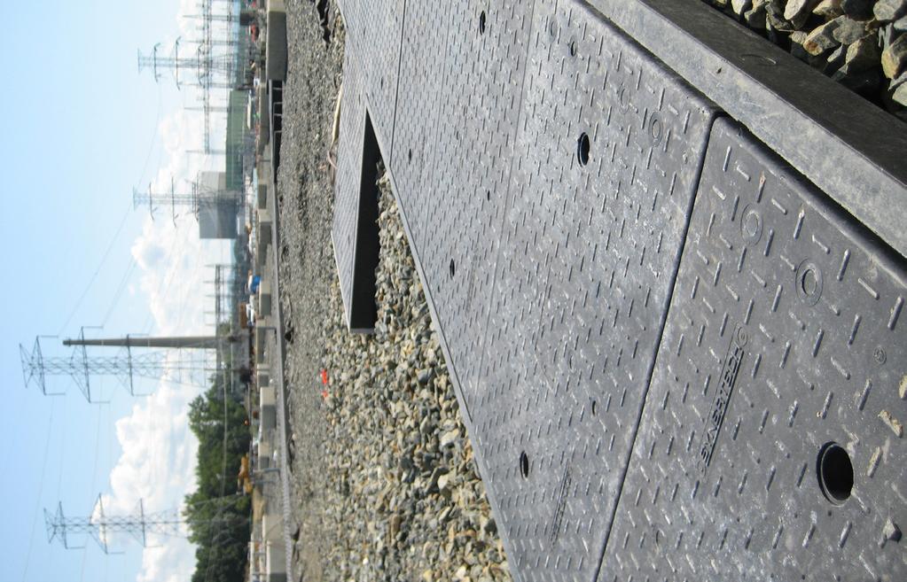
10 Protection Rods and Covers Install (optional) protection rods. Using cover lifting hooks provided, cover channels with HDPC covers. Covers should never overlap a trench seam. PROTECTION ROD COVER Proper Cover Installation Each cover should be situated on a single trench frame. Covers should not overlap two different trenches. EACH COVER IS SEATING ON A SINGLE TRENCH ONE COVER SEATING ON TWO DIFFERENT TRENCHES CORRECT INCORRECT 2018 Oldcastle, Inc. Page 10

11 Additional Trench Protection In temporary cases of repetitive traffic or special vehicle loads, matting may be placed over the trench for additional protection. Oldcastle recommends the following specifications. Other methods and materials may be used based on site specific soil conditions, trench orientation, vehicle loads, etc. 2 LAYERS OF 3 4" PLYWOOD MATTING FOR WEAR & TEAR, OVER TRENCH AND COVERS NON STRUCTURAL: AS REQUIRED BY TRUCK LOAD 2' MIN. COVERS TRENCH 2' MIN. MATTING AND TRENCH MUST BE WELL-SUPPORTED PER PLASTIBETON INSTALLATION MANUAL 1" THK. (OR GREATER) STEEL PLATE MATTING FOR STRUCTURAL SUPPORT OR WEAR & TEAR, OVER TRENCH AND COVERS STRUCTURAL: AS REQUIRED BY TRUCK LOAD 2' MIN. COVERS TRENCH 2' MIN. MATTING AND TRENCH MUST BE WELL-SUPPORTED PER PLASTIBETON INSTALLATION MANUAL 2018 Oldcastle, Inc. Page 11

![COVER MODEL SHORTEST CENTER LENGTH C6 19-5/8 [497 mm] C12 19-5/8 [497 mm] C20 19-5/8 [497 mm]](/docs-images/85/92705328/images/12-1.jpg "C30 11-5/8 [297 mm] C40 11-5/8 [297 mm] Only cut at 1 end of the cover, not at both, to keep")


12 Cover Cut Parameters All Covers, General Requirements Shortest nominal / center length of cover is half of the nominal length. See table below. Valid for straight and angle cut. COVER MODEL SHORTEST CENTER LENGTH C6 19-5/8 [497 mm] C /8 [497 mm] C /8 [497 mm] C /8 [297 mm] C /8 [297 mm] Only cut at 1 end of the cover, not at both, to keep one of both end intact. All T configurations need steel support, except for the C6/trench 68 model. (Typical T configuration, 2016 trench model shown) Cover Model C6, for 68 Trench Model No additional requirement for straight cuts. Cover can be cut at all angle, up to 45, without the need of a steel support. Consult factory if an angle above 45 is required Oldcastle, Inc. Page 12


 A cut cover at 45, in the T45 configuration use")
13 Cover Model C12 and C20, for Trenches Model 128, 1216, 2012 and 2016 No additional requirement for straight cuts. Cover can be cut at an angle up to 22.5, without the need of a steel support. (22.5 cut on a C12 cover shown) When covers are cut at 23 and above, a special steel support is required. Consult factory. This would be occurring when a deviation of an angle between 46 and 89 is present on the trench layout. (Example of a layout that would require a special steel support) A cut cover at 45, in the T45 configuration use a standard steel support as specified on the standard deviation BOM. ( T45 deviation, 2016 model. Steel support in blue.) 2018 Oldcastle, Inc. Page 13

14 Cover Model C30, for Trenches Model 3012 and 3016 For straight cuts, we do not recommend cutting between the values below. In these areas, steel rebar are present, making the cutting step more complex. 15-5/8 and 17-3/8 [398 mm and 443 mm] 21-7/8 up to full length [557 mm and longer] Cover can be cut at an angle up to 7.5, without the need of a steel support. Shortest edge must be at least 17-1/2 [445 mm] long. (7.5 cut on a C30 cover shown) When cover are cut at 8 and above, a special steel support is required. Consult factory. This would be occurring when a deviation of an angle between 16 and 89 is present on the trench layout. (Example of a layout that would require a special steel support) For a trench deviation of 45 exactly, resulting in cut cover with an angle of 22.5, a standard steel support is available. Please see on the specific drawings. A cut cover at 45, in the T45 configuration use a standard steel support as specified on the standard deviation BOM Oldcastle, Inc. Page 14

![Shortest edge must be at least 17-1/2 [445 mm] long. (7.5 cut on a C40 cover shown) When cover are cut at 8 and above, a special steel support is required. Consult factory.](/docs-images/85/92705328/images/15-1.jpg "This would be occurring when a deviation of an angle between 16 and 89 is present on the trench layout. (Example of a layout that would require a special steel support.")
15 Cover Model C40, for 4016 Trench Model For straight cuts, we do not recommend cutting between the values below. In these areas, steel rebar are present, making the cutting step more complex. 14-1/2 and 16-3/4 [370 mm and 425 mm] 20-7/8 up to full length [530 mm and longer] Cover can be cut at an angle up to 7.5, without the need of a steel support. Shortest edge must be at least 17-1/2 [445 mm] long. (7.5 cut on a C40 cover shown) When cover are cut at 8 and above, a special steel support is required. Consult factory. This would be occurring when a deviation of an angle between 16 and 89 is present on the trench layout. (Example of a layout that would require a special steel support. Trench 3012 is shown, but this apply to 4016 trench model) For a trench deviation of 45 exactly, resulting in cut cover with an angle of 22.5, a standard steel support is available. Please see on the specific drawings Oldcastle, Inc. Page 15

![(Shortest nominal length) Shortest single wall length of 12 [305 mm].](/docs-images/85/92705328/images/16-2.jpg "(Shortest single wall length) Whenever possible, only cut at 1 end of the trenches, not at")
16 Trench Body Cut Parameters All Trenches Models, General Requirements Shortest nominal / center length of 23-5/8 [600 mm]. (Shortest nominal length) Shortest single wall length of 12 [305 mm]. (Shortest single wall length) Whenever possible, only cut at 1 end of the trenches, not at both, to keep one of both end entire. (Cut at 1 end only, not both) 2018 Oldcastle, Inc. Page 16

 On a trench with a door cut, if the end of the trench pass thru the cable exit opening")
![in the bottom of the trench, maximum length of 6 [152 mm] is acceptable between the end of the trench and](/docs-images/85/92705328/images/17-2.jpg "the cable exit (Maximum length) For «Four-way» / «cross» trench connection, cut the doors on both side of")

17 All Trenches Models, Door Cuts When a door is aligned with the cable exit opening in the bottom of the trench, a minimum distance of 6 [152 mm] is required between the end of the trench and the cable exit opening. (Minimum distance) On a trench with a door cut, if the end of the trench pass thru the cable exit opening in the bottom of the trench, maximum length of 6 [152 mm] is acceptable between the end of the trench and the cable exit opening. (Maximum length) For «Four-way» / «cross» trench connection, cut the doors on both side of trenches, to avoid extra long «tongues» without vertical wall on trenches. (Typical «Four-ways» / «cross» connection. Steel support are required but not shown for clarity.) All Trenches Models, Angle Cuts Both trenches should be cut to result in a perfect fit. (Typical angle deviation) 2018 Oldcastle, Inc. Page 17
 All Trenches Models, Vertical Deviation Typically, up to 5 of vertical deviation, only 1")

 (Typical vertical")

18 On 1 trench, the maximum cut angle is 45. Consult factory for any situation require angle above 45. (Maximum angle cut on a trench) All Trenches Models, Vertical Deviation Typically, up to 5 of vertical deviation, only 1 trench is cut. A small offset is resulting from that under the trench but is relatively small so trenches can be installed without issue. Above 5 of vertical deviation, both connecting trenches should be cut, resulting in a perfect fit. (Typical vertical deviation, side view, only the trench in the middle is cut at 4 angle, both ends) (Typical vertical deviation, side view, all the 3 trenches are cut with a 10 angle) 68 Trench Models No additional specific cut parameter. 128 and 1216 Trench Models For straight and angle cuts, a minimum distance of 6 [152 mm] is required between the end of the trench and the cable exit opening. (Minimum distance between end of trench and cable exit opening - Straight cut) 2018 Oldcastle, Inc. Page 18

![end of the opening is 14 [356 mm].](/docs-images/85/92705328/images/19-1.jpg "(Maximum distance between end of trench and end of cable exit opening Straight cut) (Maximum distance")

 2012 and 2016 Trench Models No")
19 (Minimum distance between end of trench and cable exit opening Angle cut) For straight and angle cuts, if cut pass thru the cable exit opening, the maximum distance between the end of the trench and the end of the opening is 14 [356 mm]. (Maximum distance between end of trench and end of cable exit opening Straight cut) (Maximum distance between end of trench and end of cable exit opening Angle cut) For doors cuts, care should be taken to avoid having steel support leg aligned with cable exit opening in the bottom, resulting in improper steel support rest. (Example of a situation to avoid. The steel support is not properly resting on the trench bottom) 2012 and 2016 Trench Models No additional specific cut parameter and 3016 Trench Models No additional specific cut parameter Oldcastle, Inc. Page 19
 «T45» deviation is not possible for 4016 trench.")
20 4016 Trench Models 90 deviation is different from other trench size. Trenches are not cut at 45, but is composed of a straight cut, a door cut and an end plate. See standard deviation section. Maximum cut angle on a single piece is Consult factory for any situation require angle above (Maximum angle cut on a 4016 trench) «T45» deviation is not possible for 4016 trench. Typical option for this connection is the use of a double run of trench model 2016 at connection point. Contact factory for details. Field Drilling The sidewall area should not be reduced more than 100 SQ.IN. Oldcastle Engineering should be consulted for field modifications that do not conform with this document. "B" 5" MAX. HOLE DIAMETER 7" MIN. BETWEEN HOLES "A" FIELD DRILLING TO BE LIMITED TO RECESSED AREA OF TRENCH (DOTTED RED LINE) MODEL A B /8 4 3/ /2 2 3/ / /8 5 1/ /4 9 1/ /8 5 9/ /4 10 5/ /4 8 1/ Oldcastle, Inc. Page 20
 1/4 x 2-1/4 wedge anchors with washers and nuts")


21 End Plate Installation PI-180 Materials and Tools (4) 1/4 x 2-1/4 wedge anchors with washers and nuts (1) End Plate Hammer Drill with a 1/4 carbide or diamond drill bit Pneumatic Impact Wrench Hammer 1 1. Square the end plate vis-a-vis the place where it should be installed. 2. Drill the end plate and the trench in the four predetermined locations. 3. Insert the anchors into the holes and firmly press them with a hammer Tighten the nuts using a pneumatic impact wrench Oldcastle, Inc. Page 21
 Washers")
 Unistrut (1) Fire Plate Hammer")


22 Fire Stop Installation PI-178 Materials and Tools (4) Washers 1/2 (4) Washers 1 (4) Zamacs 3/4 (2) Unistrut (1) Fire Plate Hammer Drill with a 1/4 carbide or diamond drill bit Circular saw with Diamond Blade Pneumatic Hammer 1. Install Unistrut a. Place Unistrut perpendicular to the trench in the desired location. b. Drill holes 3/4 deep to insert the Zamacs. c. Drive Zamacs using a pneumatic hammer. 1a 1b 2. Cut the fire stop according to the cables present in the trench. 3. Insert the fire stop in the Unistrut. 1c Oldcastle, Inc. Page 22
Plastibeton Trench System. Installation Packet
 Plastibeton Trench System Installation Packet Plastibeton Installation Guide This Installation Guide is intended to assist in the preparation and installation of Plastibeton products manufactured by Oldcastle
SUBSTATION SECURITY WALL INSTALLATION MANUAL
 SUBSTATION SECURITY WALL INSTALLATION MANUAL JULY 26, 2016 OLDCASTLE PRECAST, INC. 3000 New McEver Rd, Acworth, Ga 30101 Substation Security Wall Installation Manual This Installation Manual is intended
CONTENTS TOOL LIST U P S I D E I N N O V A T I O N S, L L C RAMP AND STEP SYSTEM ASSEMBLY INSTRUCTIONS. Revised: June 2013
 U P S I D E I N N O V A T I O N S, L L C RAMP AND STEP SYSTEM ASSEMBLY INSTRUCTIONS TOOL LIST Required Tools: - Reciprocating Saw with Metal Cutting Blade - Drill - 7/16 Drill Bit for Metal Drilling -
14 x 14 super quad. VISIT LINK BELOW FOR INSTALL VIDEO
 in-ground installation instructions & user guide 14 x 14 super quad VISIT LINK BELOW FOR INSTALL VIDEO https://www.maxairtrampolines.com/pages/support-information-videos Page 2 TABLE OF CONTENTS Materials,
Bumper Sign INSTALLATION INSTRUCTIONS
 Bumper Sign INSTALLATION INSTRUCTIONS BUMPERSIGN TOOL CHECKLIST SDS MAX Rotary Hammer Drill Marker/Pencil SDS MAX 1 Carbide Drill Bit Tape Measure Torque Wrench with ½ Drive Power Source Vacuum ½ Drive
10 x 12 home air pro. VISIT LINK BELOW FOR INSTALL VIDEO
 in-ground installation instructions & user guide 10 x 12 home air pro VISIT LINK BELOW FOR INSTALL VIDEO https://www.maxairtrampolines.com/pages/support-information-videos Page 2 TABLE OF CONTENTS Materials,
7 x 14 flybed tramp. VISIT LINK BELOW FOR INSTALL VIDEO
 in-ground installation instructions & user guide 7 x 14 flybed tramp VISIT LINK BELOW FOR INSTALL VIDEO https://www.maxairtrampolines.com/pages/support-information-videos Page 2 TABLE OF CONTENTS Materials,
SKT-SP Tangent Terminal
 Assembly Instructions for metric SKT-SP Tangent Terminal & FLEAT-SP Flared Terminal SP Standard Post System Guardrail Terminals ROAD SYSTEMS, INC. P. O. Box 2163 Big Spring, Texas 79721 Phone: (432) 263-2435
5 5 8 " 60" 53 8 " " 7" 5 1 2" 7" " FIVE MODELS TO MEET YOUR DESIGN REQUIREMENTS.
 Installation Manual GIRT LAMINATEDATED WOOD COLUMN 1/4" SCREW 1/2" BOLT STRUCTURAL REINFORCING BRACKET SKIRT BOARD 10,000 PSI PRECAST CONCRETE CONTINUOUS STEEL REINFORCEMENT GALV VANIZED STEEL UPLIFT ANCHORS
Equilibrium. Conference Table. Installation Instruction. Revision B 11/07/16
 Equilibrium Conference Table Installation Instruction Revision B 11/07/16 Equilibrium End User Agreement Enwork Equilibrium table bases must be installed directly onto a four inch minimum thickness concrete
SHADOWBOX INSTALLATION FOR: Standard 6 H x 8 W Shadowbox Fence 5 x 5 Routed Posts Dog Ear or Straight-Edge Pickets 1.75 x 3.5 Rail
 SHADOWBOX INSTALLATION FOR: Standard 6 H x 8 W Shadowbox Fence 5 x 5 Routed Posts Dog Ear or Straight-Edge Pickets 1.75 x 3.5 Rail Storage and Handling Fence Preparation and Layout Locate and Set Posts
DOCK WEDGE - STANDARD
 DOCK WEDGE - STANDARD INSTALLATION INSTRUCTIONS WOOD HEADER READ ALL INSTRUCTIONS BEFORE INSTALLING SEAL. SUPER SEAL MFG. LTD. WILL NOT BE HELD RESPONSIBLE FOR IMPROPER INSTALLATION OF ANCHORING DEVICES,
Installation Guide. Capped Cellular PVC Fencing. Table of Contents. Storage and Handling Tools Needed Fence Layout and Locating Posts
 Capped Cellular PVC Fencing Installation Guide Table of Contents Storage and Handling Tools Needed Fence Layout and Locating Posts Installation instructions 4 x 4 Over Sleeve Post - 3.5 Rail Privacy Shadowbox
Installation Instructions
 Column & Beam Units with Debris Netting Installation Instructions Laminated Wood Systems, Inc. Seward, Nebraska 800-949-3526 2015 LWS, INC. AVR-NET INSTALL 05-12-16 AVR Installation Notes 1 Safety The
Installation Manual for Gate Guard
 Installation Manual for Gate Guard Fast Opening Barrier Gate for Emergencies and Contra Flow Innovative safety technology from SGGT of Germany TABLE OF CONTENTS Page Number Preface 3 Introduction 3 System
INSTALLATION INSTRUCTIONS
 INSTALLATION INSTRUCTIONS HIGH PRESSUE LAMINATE (HPL) TOILET PARTITIONS 1030 TrimLineSeries 1040 DesignerSeries Includes continuous hardware option.65. IMPORTANT: Storage and Handling Information on last
INSTALLATION INSTRUCTIONS
 INSTALLATION INSTRUCTIONS SOLID PHENOLIC TOILET PARTITIONS 1080 DuraLineSeries Class-A Fire Rated Includes Institutional Hardware Option.67 IMPORTANT: Storage and Handling Information on last page. Review
END VIEW WEDGE TOP VIEW WOOD POST FOUNDATION DETAILS
 X (NOMINAL POST) 1-1/ DIA. 2 HOLES X 8" (NOMINAL POST) 3-1/ DIA. 2 HOLES TAPERED HARD WOOD WEDGES (HARDWOOD WEDGE TO BE OAK, MAPLE OR OTHER APPROVED DENSE HARDWOODS) TO HOLD POST IN A STABLE POSITION AFTER
CertainTeed INSTALLATION GUIDE SIMTEK FENCE PRODUCTS. Fence Installation Guide 3', 4' & 6' High
 CertainTeed INSTALLATION GUIDE SIMTEK FENCE PRODUCTS Fence Installation Guide 3', 4' & 6' High INSTALLATION GUIDE These instructions are designed to assist both professional installers and do-it-yourselfers
Sliding Door Kit
 YOU MUST READ THIS DOCUMENT BEFORE YOU BEGIN TO ASSEMBLE THE DOOR KIT. Thank you for purchasing this GrowSpan door kit. When properly assembled and maintained, this product will provide years of reliable
Equilibrium Credenza
 Equilibrium Credenza Cantilevered base & Tapered Credenza Installation Instruction EI0006 Revision A 8/20/18 Equilibrium End User Agreement Enwork Equilibrium credenza bases must be installed directly
HONEYCOMB SHADES. Cordless INSIDE MOUNT. A few simple tools are required: STANDARD HARDWARE OPTIONAL HARDWARE
 HONEYCOMB SHADES Cordless GETTING STARTED BRACKET INFORMATION A few simple tools are required: Steel Tape Measure Pencil Level (for outside mount) The brackets you received with your product are REQUIRED
TOOLS REQUIRED Metal Wood Wood and Metal Screws. #16 Drill #12-24 Tap. 1/8 Drill
 DEVICES COVERED IN THIS DOCUMENT: 4700S Surface Vertical Rod Device 4700SF Fire Exit Surface Vertical Rod Device TOOLS REQUIRED Metal Wood Wood and Metal Screws Sex Bolts #7 Drill ¼ -20 Tap #16 Drill #12-24
Installation Instructions Split Shake, Staggered Shake, Shingle, Perfection Shingle, and Shapes
 Installation Instructions Split Shake, Staggered Shake, Shingle, Perfection Shingle, and Shapes General Guidelines These instructions show one type of installation and are intended for the professional
5/16" Flange nut. Bolt Keeper Plate (8" Sq. SYS.) (3) 1/2" x 3" Hex head connector zinc plated bolt w/ washers and nut. Anchor 3" sq. 7 Ga.
 (3) 1/2 x 3 Hex head connector zinc plated bolt w/ washers and nut. Anchor 3 sq. 7 Ga.") 2 1/2" x 2 1/2" x 10 Ga. 6" 5" 4" Variable Slipbase (8" Sq. SYS.) 5/16 Corner Bolt W/ nut 5/16" Flange nut Stub Insert (8" Sq. SYS.) Bolt Keeper Plate (8" Sq. SYS.) (3) 1/2" x 3" Hex head connector zinc
2 1/2" x 2 1/2" x 10 Ga. 6" 5" 4" Variable Slipbase (8" Sq. SYS.) 5/16 Corner Bolt W/ nut 5/16" Flange nut Stub Insert (8" Sq. SYS.) Bolt Keeper Plate (8" Sq. SYS.) (3) 1/2" x 3" Hex head connector zinc
PRIVACY INSTALLATION FOR: Standard 6 H x 8 W Privacy Fence 4 x 4 Post Sleeve & Brackets Dog Ear or Straight-Edge Pickets 1.75 x 3.
 PRIVACY INSTALLATION FOR: Standard 6 H x 8 W Privacy Fence 4 x 4 Post Sleeve & Brackets Dog Ear or Straight-Edge Pickets 1.75 x 3.5 Rail Storage and Handling Fence Preparation and Layout Locate and Set
 For Wallbed models: KING SIZE INSTRUCTION BOOKLET #C1 Watch step by step installation instructions at: https://www.wallbedsbywilding.com/wallbed-installation-studio-series/ WARNING! ALL MURPHY/WALLBED
PORTA-FAB Cleanroom Wall Systems
 PORTA-FAB Cleanroom Wall Systems FABLINE BATTEN 2000 INSTALLATION INSTRUCTIONS IMPORTANT Porta-Fab Advises A Thorough Reading of These Instructions Before Beginning Installation. INTRODUCTION Porta-Fab
INSTALLATION INSTRUCTIONS
 INSTALLATION INSTRUCTIONS LAMINATED P LASTIC TOILET PArTITIONS 1540 ClassicSeries with Options IMPORTANT: Storage and Handling Information on last page. For faster, easier installation, please review these
Installation Instructions. Tools Needed. Tape measure. Level. Shovel or Post hole digger. Concrete. Drill. Stakes. Mallet or hammer.
 Installation Guide EcoStone Fence 1330 West 400 North Orem, UT 84057 Toll Free 1.866.648.9336 Tel. 1.801.655.5236 Fax 1.801.655.5240 www.ecostonefence.com Installation Instructions Introduction. These
Dura-Lock Roof System
 DLR-14 Dura-Lock Roof System Assembly and Installation Instructions Read the instructions before starting the job. They explain the steps required to produce a finished product that will meet factory specifications.
Installation Instruction
 Tools Needed for Assembly Stud finder (for wood stud wall) Pencil Mark Electric drill Wood Stud Wall Installation Step 1. Locate the Wood Studs Installation Instruction Drill bit (for wood stud wall) Masonry
MUDPLASTERED BAMBOO-SHELTER as temporary dwelling until the real house can be built can last for 6-8 years
 MUDPLASTERED BAMBOO-SHELTER as temporary dwelling until the real house can be built can last for 6-8 years Things needed: (a) 6 pcs thick poles 7 feet long (b) 2 pcs thick poles 9 feet long (c) 3 pcs beams
Tilting & Swiveling Plasma/LCD Flat Panel Wall Mount Installation Guide Model: A380SM
 Tilting & Swiveling Plasma/LCD Flat Panel Wall Mount Installation Guide Model: A380SM Easy installation Built-in level for easy positioning Corrective leveling adjustments after installation Forward /
FENCE INSTALLATION GUIDE 8 HIGH WALLS
 FENCE INSTALLATION GUIDE 8 HIGH WALLS 1.866.648.9336 www.simtekfence.com INSTALLATION GUIDE These instructions are designed to assist both professional installers and do-it-yourselfers of SimTek decorative
GE Monogram. Installation. Instructions. Microwave Oven. Under Cabinet Installation. and. JX827 Series Built-In Kit. Models.
 GE Monogram Installation Instructions Under Cabinet Installation and JX827 Series Built-In Kit Models ZEM200 Series CAUTION WARNING Before you begin Read these instructions completely and carefully. IMPORTANT:
Stargrip series 3000 Mechanical Joint Wedge Action Restraint for Ductile Iron Pipe
 Stargrip series 3000 Mechanical Joint Wedge Action Restraint for Ductile Iron Pipe INFORMATION The Stargrip Mechanical Joint Restraint System is a unique product with a proven design that provides an exceptional
INSTALLING YOUR NEW SPRING LIFT ARM KIT
 INSTALLING YOUR NEW SPRING LIFT ARM KIT 1. Measure the distance that the roof is to be raised. [If your lift system is completely non-functional, you will need to calculate or estimate this distance as
Assmann Corporation of America TANK INSTALLATION AND USE GUIDELINES FOR BULK STORAGE TANKS
 Assmann Corporation of America TANK INSTALLATION AND USE GUIDELINES FOR BULK STORAGE TANKS General Information Assmann polyethylene storage tanks are manufactured to give you the toughest, most reliable
K.D. LOCKER ASSEMBLY INSTRUCTIONS
 K.D. Locker Assembly Instructions PN 0860 K.D. LOCKER Updated /05 ASSEMBLY INSTRUCTIONS These Instructions Cover 3 Types of Lockers: VANGUARD, GUARDIAN AND INVINCIBLE II Contents General Instructions 1
Chapter 1. Beam and Sill Plates
 Chapter 1. Beam and Sill Plates 1.1 ESTABLISHING SQUARE SILL PLATE CHALK LINES 1.2 INSTALLING TREATED SILL PLATES 1.3 INSTALLING LAMINATE BEAM Tools needed by volunteers: Hammer Nail apron Tape measure
Assembly & Installation Guide (Metric)
") Assembly & Installation Guide (Metric) INFRASTRUCTURE FOR LIFE RS Technologies www.rstandard.com Email Toll Free Phone Fax info@grouprsi.com +1 877 219 8002 +1 403 219 8000 +1 403 219 8001 2421 37th Avenue
Assembly & Installation Guide (Metric) INFRASTRUCTURE FOR LIFE RS Technologies www.rstandard.com Email Toll Free Phone Fax info@grouprsi.com +1 877 219 8002 +1 403 219 8000 +1 403 219 8001 2421 37th Avenue
MM340 Installation Instructions IMPORTANT SAFETY INSTRUCTIONS - SAVE THESE INSTRUCTIONS
 MM30 Installation Instructions IMPORTANT SAFETY INSTRUCTIONS - SAVE THESE INSTRUCTIONS Please read this entire manual before you begin. Do not unpack any contents until you verify all requirements on PAGE.
- Before You Begin - Standard Apex / Tall Apex Shed Kit Instructions IMPORTANT!
 Customer Service: (801)754-3334 810 W Utah Ave #8 Payson, Utah 84651 email: apexshedcompany@gmail.com Standard Apex / Tall Apex Shed Kit Instructions Tools Needed: Framing Hammer Tape Measure (25 ft.)
IMPORTANT: installation. FLOOR ANCHORED CEILING HUNG OVERHEAD BRACED FLOOR-TO- CEILING ANCHORED
 INSTALLATION INSTRUCTIONS MAXIMUM PRIVACY COMPACT LAMINATE TOILET PARTITIONS 2080 DuraLineSeries 2180 DuraLineSeries Class-A Fire Rated Includes Institutional Hardware Option.67 IMPORTANT: Storage and
INSTALLATION INSTRUCTIONS
 INSTALLATION INSTRUCTIONS SOLID PHENOLIC TOILET PARTITIONS 1080 DuraLine Series 1180 DuraLine Series Class-A Fire Rated IMPORTANT: Review these instructions thoroughly prior to installation. FLOOR ANCHORED
RBP-1215B-RX DODGE RAM QUAD CAB RX3
 RBP-1215B-RX3 2002-2017 DODGE RAM 15-3500 QUAD CAB RX3 Passenger side RX-3 Side Step Drill Template Passenger side rear Modular Bracket (6) L Support Brackets Driver side rear Modular Bracket Driver side
MM540 Installation Instructions IMPORTANT SAFETY INSTRUCTIONS - SAVE THESE INSTRUCTIONS
 MM50 Installation Instructions IMPORTANT SAFETY INSTRUCTIONS - SAVE THESE INSTRUCTIONS Please read this entire manual before you begin. Do not unpack any contents until you verify all requirements on PAGE.
10 x 10 Flat Top Two Tone Pergola
 0 x 0 Flat Top Two Tone Pergola Models: Bordeaux ASSEMBLY GUIDE OPTIONAL ACCESSORIES Arch Kit System ( Arches) Privacy Fence Panel System ( Panels & Middle Post) Bolt Down Bracket Kit ( for Pergola) Ver.0-00
KOLO SHELTER Installation Instructions Parts List
 Parts List Roof Cap Rafter Upright Polycarbonate Polycarbonate Drop Polycarbonate Flange Center Weldment (Short length shown above) Polycarbonate Edge Bolt.25 x 6.5 Bolt.625 x 7.5 Threaded Rod.75 x 14
TOLL FREE:(888) FAX:(941) ASSEMBLY of ProTEC CONCRETE STRUCTURAL INSULATED PANEL
 FAX:(941) ASSEMBLY of ProTEC CONCRETE STRUCTURAL INSULATED PANEL") ASSEMBLY of ProTEC CONCRETE STRUCTURAL INSULATED PANEL The ProTEC panels are manufactured with grooves on all four sides to accept the steel components. This grooving applies to the regular panel whose
ASSEMBLY of ProTEC CONCRETE STRUCTURAL INSULATED PANEL The ProTEC panels are manufactured with grooves on all four sides to accept the steel components. This grooving applies to the regular panel whose
PRORAC CONTRACTOR SERIES UNIVERSIAL STEEL TRUCK / CAP RACK INSTALLATION INSTRUCTIONS
 PRORAC CONTRACTOR SERIES UNIVERSIAL STEEL TRUCK / CAP RACK INSTALLATION INSTRUCTIONS 1000 Lb. Capacity Bed Mount 750 Lb. Capacity Cap Mount Package Contents: Parts Hardware (4) Legs (12) 3/8-16 x 1-1/4
C4 Fabrication Rock Slider Installation 14+ 5th Gen 4Runner w/o KDSS
 C4 Fabrication Rock Slider Installation 14+ 5th Gen 4Runner w/o KDSS Thank you for your purchase of the C4 Fabrication s 5th Gen 4Runner Rock Sliders! This product was carefully crafted to ensure a perfect
Mounting Instructions Item No.: xxx
 Mounting Instructions Item No.: 271.92.xxx Wall-Beds 1 General Notes For vertical folding beds Successful and safe installation of Bed-Lift and construction of casework requires a professional skill level
Installation Instructions - Model V4JSD 1
 Installation Instructions - Model V4JSD 1 Support Assemblies: Parts list: (Note see enclosed cut sheet for quantities and dimensional information) A vertical structural member (1 ½ x 1 ½ modular frame)
Tilting Flat Panel Wall Mount Installation Guide
 Tilting Flat Panel Wall Mount Installation Guide Model: A580TM Easy installation Built-in level for easy positioning Safety bolts lock the TV on the mount Easy to adjust tilt angles: +5 to -15 degrees
BioPrism Solid Surface
 Please read all instructions before installing products. These instructions are intended for use with InPro s standard toilet partitions, which include 58 high doors and wall panels, when deviating from
TP4463. ASSeMBly INSTruCTIONS FLAT PANEL TV MOUNTING SYSTEM OPTION 1 OPTION 2 OPTION 3
 TP63 FLAT PANEL TV MOUNTING SYSTEM OPTION 1 OPTION 2 OPTION 3 Flat Panel TV Stand Stand with TV Mounting System Stand with Wall Mount ASSeMBly INSTruCTIONS for your safety, please follow these precautions:!
Assembly Instructions for. for 31" MGS (Midwest Guardrail System) ROAD SYSTEMS, INC.
 ROAD SYSTEMS, INC.") MSKT Assembly Instructions for MASH Tangent Terminal for 31" MGS (Midwest Guardrail System) ROAD SYSTEMS, INC. P. O. Box 2163 Big Spring, Texas 79721 Phone: (432) 263-2435 FAX: (432) 267-4039 Technical
MSKT Assembly Instructions for MASH Tangent Terminal for 31" MGS (Midwest Guardrail System) ROAD SYSTEMS, INC. P. O. Box 2163 Big Spring, Texas 79721 Phone: (432) 263-2435 FAX: (432) 267-4039 Technical
Dual Arm Tilt LCD Mount
 Installation Manual model # 51324 M o u n t i n g S y s t e m s Dual Arm Tilt LCD Mount Fits Displays 13 to 32 Supports Up to 50 lbs (23 kgs) Projection from Wall from 3 to 17 Meets VESA Standards 50/75/100,
Twin-Wall Double Swinging Door Kit
 115021 Twin-Wall Double Swinging Kit READ THIS DOCUMENT BEFORE YOU BEGIN Thank you for purchasing this GrowSpan door kit. When properly assembled and maintained, this product will provide years of reliable
SILVERBACK INSTALLATION MANUAL
 SILVERBACK INSTALLATION MANUAL R-SERIES SOLAR RACKS T OLL FREE 866-766-3727 WWW.ROOFSCREEN.COM Introduction... 2 The Silverback Solar Racking System... 2 This manual... 2 Application... 2 System Overview...
START HERE BEFORE YOU BEGIN FIG 1 STEP 2
 PROFESSIONAL INSTALL RECOMMENDED REAR MODULAR / MULTI LED ROOF MOUNTS PART#: Z350040 / Z350050 REAR ROOF LED LIGHT MOUNTS Parts included (1) - Driver Side Roof Mount Upright (1) - Passenger Side Roof Mount
Steel Sound Enclosure
 Steel Sound Enclosure INSTALLATION MANUAL List of tools recommended for use during installation: vise grips c clamp ladder electric drill drill bits / taps as req d screw drivers hammer rubber mallet pipe
INSTALLATION INSTRUCTIONS FOR PLASCORE F5075 FRAME WALL
 INSTALLATION INSTRUCTIONS FOR PLASCORE F5075 FRAME WALL The following information is provided by Plascore, Inc., as a general guideline for the installation of the F5075 Frame Wall System. This information
https://www.wallbedsbywilding.com/wallbed-installation-studio-series/
 For Wallbed models: KING SIZE INSTRUCTION BOOKLET #C1 Watch step by step installation instructions at: https://www.wallbedsbywilding.com/wallbed-installation-studio-series/ WARNING! ALL MURPHY/WALLBED
Block Foundation. From the 1950s through the 80s. Hydraulically driven. piers provide bearing. for a settling foundation
 RESCUING FIXING A A Block Foundation Hydraulically driven piers provide bearing for a settling foundation From the 1950s through the 80s before poured concrete became the norm many homes in northern New
Oxford Stalls Installation Instructions
 Oxford Stalls Installation Instructions RAMM Horse Fencing and Stalls 13150 Airport Hwy. Swanton, OH 43558-9615 1-800-434-8456 Rev. 8/15/17 Before You Start Typical stall sizes are 10 x 10, 12 x 12 or
STRATUS SHELTER. Take bike parking to new heights
 Take bike parking to new heights The Stratus Shelter is a striking bike shelter option for any transit station, university campus, or multi-family residential building project. It is constructed of American
BBULTRA Basketball Tower Installation
 Ph: 1300 500 314 Basketball Tower Installation Thank you for your purchase of the Ultra adjustable Basketball system. To ensure that our equipment will provide years of use to you, we are including this
INSTALL INSTRUCTIONS WELCOME TO THE NEWAGE PERFORMANCE CABINETRY SERIES NEWAGE STEEL WELDED CABINETRY
 NEWAGE STEEL WELDED CABINETRY WELCOME TO THE NEWAGE PERFORMANCE CABINETRY SERIES ALL CABINETS MUST BE MOUNTED TO STUDS ON A SECURE WALL, AS PER THESE INSTRUCTIONS. FAILURE TO DO SO MAY RESULT IN SERIOUS
8x12 SpaceMaker Garden Shed Assembly Manual
 8x12 SpaceMaker Garden Shed Assembly Manual Version #6 Revised June / 2007 Thank you for purchasing a 8x12 SpaceMaker Garden Shed. Please take the time to identify all the parts prior to assembly. Safety
Chapter 23. Garage Construction
 Chapter 23. Garage Construction 23.1 ESTABLISHING CHALK LINES 23.2 MEASURING AND CUTTING WALL PLATES 23.3 MARKING WINDOW & DOOR LOCATIONS ON EXTERIOR WALL PLATES 23.4 MARKING STUDS ON EXTERIOR WALL PLATES
installation care & maintenance instructions lifecycledecking.com 25-year limited residential warranty 20-year limited commercial warranty
 installation care & maintenance instructions lifecycledecking.com 25-year limited residential warranty 20-year limited commercial warranty Installation Instructions As with any building project, use proper
Installation Instructions
 Installation Instructions For Models: Model Number / Description File Name 1540 Classic Series P-Lam Toilet Partitions 1540.pdf 1 INSTALLATION INSTRUCTIONS LAMINATED PLASTIC TOILET PARTITIONS 1540 Classic
INSTALLATION INSTRUCTIONS FOR VERTICAL ROD ASSEMBLY, MODEL VRA-143
 INS-143/PM April 20, 2007 Detex Corp, 302 Detex Drive, New Braunfels, Texas 78130 (830)629-2900/1-800-729-3839/ FAX(830)620-6711 E-Mail: detex@detex.com Internet: www.detex.com INSTALLATION INSTRUCTIONS
/A INSTALLATION MANUAL
 02-001118/A INSTALLATION MANUAL LEVITATION TV MOUNT UNIVERSAL TV MOUNT FOR 55"-85" PANEL TV'S 125 POUND MAXIMUM WEIGHT IMPORTANT SAFETY INSTRUCTIONS - SAVE THESE INSTRUCTIONS - PLEASE READ ENTIRE MANUAL
ClearSpan Hydroponic Table Kit
 ClearSpan Hydroponic Table Kit Hydroponic Table Kit (The 109314 (4' x 16') model is shown.) Designed to grow healthy plants without soil using mineral-nutrient solutions. 2009 ClearSpan All Rights Reserved.
PAK Drum Roll Top Assembly Instructions. Note: 2 people will be required to assemble roll top
 PAK901 4 Drum Roll Top Assembly Instructions Note: 2 people will be required to assemble roll top PLEASE READ ASSEMBLY INSTRUCTIONS CARFULLY Tools required: 5/8 Socket & Ratchet 9/16 Deep Well Socket &
Installation Instructions
 Installation Instructions SRT-350 8 POST Guardrail End Treatment Revised July 2005 TRINITY HIGHWAY SAFETY PRODUCTS, INC. BUILDING TOMORROW S HIGHWAY SAFETY SOLUTIONS TODAY 2 SRT TM 8-POST SYSTEM FOR SPECIFIC
Installing flat panels on the MPL15 wall mount
 Installing flat panels on the MPL15 wall mount The MPL15 (DS-VW775) is a full-service video wall mount that can accommodate tiled LCD panels with up to a 400 x 400 mm VESA pattern in portrait and landscape
Woodline USA Woodline Spacer Fence System
 Woodline USA Woodline Spacer Fence System MADE IN THE USA Includes: (1) ¼ Spacer Fence (1) 3/8 Spacer Fence (1) ½ Spacer Fence (1) Hardware Package (1) 3 Piece Brass bar set (2) Setup Blocks Visit Us Online
Bulkhead Model Number and
 Bulkhead Model Number 96141-3-01 and 96142-3-01 Installing your ProMaster bulkhead is very clear cut following these instructions. Before cutting or drilling in the floor, verify the location of you gas
Post & Rail Crossbuck
 Post & Rail Crossbuck 1. Getting Started 6. Crossbuck Be sure to call underground prior to digging Assemble gates (if necessary) and decide where they will be located Stake out the fence line Space and
TS-20KD-1010 LOW PROFILE CARGO SCALE INSTALLATION GUIDE
 TS-20KD-1010 LOW PROFILE CARGO SCALE INSTALLATION GUIDE Triner Scale & Mfg. Co., Inc. 8411 Hacks Cross Rd. Olive Branch, MS 38654 Phone: 800-238-0152 Fax: 662-809-2386 Description The Triner Scale Model
PRODUCT: LOKI INSTALLATION INSTRUCTIONS. Product is covered by U.S. patents. For more information visit
 R INSTALLATION INSTRUCTIONS PRODUCT: LOKI CONFIGURATION: SINGLE DOOR MOUNT: GLASS MOUNT Product is covered by U.S. patents. For more information visit www.krownlab.com . TOOLS + MATERIALS REQUIRED TOOLS
Calf-Tel Pen System Assembly Instructions
 Calf-Tel Pen System Assembly Instructions (Instructions work for 4, 6, and the 7 Pen Systems) 1 ASSEMBLY OF PEN FRONT AND WALLS START THE ASSEMBLY BY LINING UP THE TWO UNI-DIRECTIONAL ARROWS IN THE TOP,
FENCE INSTALLATION GUIDE 6 HIGH FENCE
 FENCE INSTALLATION GUIDE 6 HIGH FENCE 1.866.648.9336 www.simtekfence.com INSTALLATION GUIDE These instructions are designed to assist both professional installers and do-it-yourselfers of SimTek decorative
MERRY GO ROUND ITEM NO: 8030
 MERRY GO ROUND ITEM NO: 8030 OWNER S MANUAL CAUTION: This unit is designed to be used safely by up to 4 children between the ages of 3 years to 8 years old with a maximum weight of 00 pounds (45.4 kgs)
INSTALLATION INSTRUCTION
 INSTALLATION INSTRUCTION Soild Phenolic Series contents page 1080 DuraLineSeries...2-21 1180 DuraLineSeries...2-21 2080 DuraLineSeries Maximum Privacy...22-41 2180 DuraLineSeries Maximum Privacy...22-41
INSTALLATION INSTRUCTIONS
 INSTALLATION INSTRUCTIONS Special-Lite Restroom Partitions IMPORTANT - BEFORE YOU START... 1. Read through these installation instructions first to understand the order of work. 2. Check all components
SM-RAZOR-T-M/L/XL. Strong Low Profile Tilt Mount for Ultra-Thin Flat-Panel TVs INSTRUCTION MANUAL
 SM-RAZOR-T-M/L/XL Strong Low Profile Tilt Mount for Ultra-Thin Flat-Panel TVs INSTRUCTION MANUAL WARNINGS: Installation of this product should be done by a qualified professional. Do not begin installation
INSTALLATION MANUAL IOWA MOLD TOOLING CO., INC. BOX 189, GARNER, IA MANUAL PART NUMBER:
 PARTS-1 Model 24562/28562 Crane INSTALLATION MANUAL IOWA MOLD TOOLING CO., INC. BOX 189, GARNER, IA 50438-0189 641-923-3711 MANUAL PART NUMBER: 99903701 Iowa Mold Tooling Co., Inc. is an Oshkosh Truck
Midwest Roadside Safety Facility
 B 64" 1626 602'-8 1/16" 183695 548'-0" 167030 1 2 3 4 5 6 7 8 9 10 11 12 14 15 16 17 18 20 21 22 23 24 25 26 27 28 29 30 31 32 33 34 35 36 373839 40 25 IMPACT 1500A 48" 12 27'-5" 8355 [] 3x7 CL A Galvanized
Patrol Box Plans by David J. Yarusso Troop 609
 Patrol Box Plans by David J. Yarusso Troop 609 Materials List: 1. One 4 x8 sheet of ½ thick cabinet grade (birch or oak) or AC plywood. If using AC grade, use the A grade surface on the outside for a clean
6a. Eight Steps to Chain-Link Fence Installation
 6a. Eight Steps to Chain-Link Fence Installation Before You Start You will need the following tools to install your chain-link fence: Post hole digger Wheelbarrow, shovel and hoe for mixing concrete Tape
Frameless Fixed Panel Slider
 INSTALLATION INSTRUCTIONS Frameless Fixed Panel Slider QCI-5279 SINGLE ROLLER WITH ANTI-JUMP DOUBLE ROLLERS QCI5279 Rev Page Certified 08/09/6 Tools: To install your New Shower Enclosure, you may need
General Prisoner Transport Install Instructions PT-2-INST
 General Prisoner Transport Install Instructions PT-2-INST 50 or 60 high x 80, 100 & 120 inch long / Double Compartment Inserts Also refer to PT-A-3XX instructions for vehicle specific mounting measurements
RLP Flat Track Hardware sliding door hardware/ barn door track
 Page 1 of 9 Installation Suggestions for: RLP Flat Track Hardware sliding door hardware/ barn door track Read these instructions to end before starting installation or ordering hardware. Reclaimed Lumber
Super Shot Adjustable Basketball System
 Model: GP5A48 Installation, Operation and Maintenance Instructions Please read all instructions before attempting installation or operation of these units SAVE THESE INSTRUCTIONS FOR FUTURE USE PUBLICATION