14 x 14 super quad. VISIT LINK BELOW FOR INSTALL VIDEO
|
|
|
- Madlyn Norman
- 5 years ago
- Views:
Transcription
1 in-ground installation instructions & user guide 14 x 14 super quad VISIT LINK BELOW FOR INSTALL VIDEO
2 Page 2 TABLE OF CONTENTS Materials, Components, and Tools: Page 3 Architect Specifications: Pages 4-5 Total Footprint: Page 4 Pit Dimensions - Front & Side Views: Page 5 Installation Instructions: Pages 6-7 Figure : Pages 8-9 Pit and Bracing : 10 Frame Setup Diagram: 11 Standard Spring Setup Guide: 12 Pad Install : Pages Oletex Diagram: 15 Foam Install : 16 Velcro Installation Diagram: 17
3 Page 3 YOUR COMPLETE TRAMPOLINE UNIT FROM MAXAIR TRAMPOLINES CONSISTS OF (104) Side Springs (10) Extra Side Springs (16) Corner Springs (1) 14 x 14 Trampoline Bed (12) Frame Pieces OPTIONAL PADDING CHOICES Deluxe Pads, Premium Pads, or Spring Pad Covers End Deck Mats MATERIALS YOU WILL NEED TO PURCHASE (1) 50 lb Case of 10 x 3/8 Galvanized Landscaping Spikes (48) 8 x 6 x 6 Wolmanized Landscaping Ties (36) 7 x 1/2 Galvanized Lag Bolts (36) 1/2 Galvanized Washers (2) 3 x 100 Roll of Landscaping Fabric (2) Yards of Crushed Stone (1/2 to 1 Diameter Stones) TOOLS Hammer Sledgehammer Circular Saw Drill and 3/8 Drill Bit 6 Level Handsaw 3/4 Socket Wrench Staple Gun
4 Page 4 TOTAL FOOTPRINT 14 x 14 super quad BED RETAINING WALL 4 DELUXE PADS 5 PREMIUM PADS
5 Page 5 IN-GROUND TRAMPOLINE HOLE - PIT DIMENSIONS - FRONT & SIDE VIEW Retaining Wall 207
6 Page 6 INSTALLATION INSTRUCTIONS 1. Dig pit to dimensions outlined on page 5 2. But ends of the landscaping ties and toenail first layer together or drill in from behind if enough room for drill and screw in backfill area. See Figure 1.1 (page 11) 3. Start building the first layer of your retaining wall. Inside dimensions of first layer of landscaping ties will be 208 x 208. Landscaping ties can vary in length, so please be sure to check your measurements. Assemble the first layer of landscaping ties, butting the ends at the corners. Make sure that it is square and level. Drill a starter hole approximately 1-2 deep in each corner using a 3/8 drill and secure four corners with one landscaping spike per corner. 4. Building up, offset each remaining layer 1/4 back from the previous layer. Drill starter holes approximately 1-2 deep and secure each layer with landscaping spikes, spaced at a minimum of every 24 inches on center. After the first layer, the corners do not need to be notched. For structural strength, please make sure to offset the joints of the landscaping ties as you build up, as well as the corners. 5. While assembling the 4th layer, 2 t-brace supports will need to be installed in the centers of both side walls. To assemble each t-support, cut one 8 landscaping tie in half, creating two 4 pieces. Align 4 sections into a T-shape and secure using landscaping spikes. A total of 2 t-brace supports will need to be constructed. See Figure Centered and extending from the edge of the pit on both sides, dig an area 50 x 37.5 x 16.5 (L x W x D) for each t-brace to rest. It is important that they be dug no deeper than 16.5 to ensure that soil remains compacted underneath the t-braces. See Figures 1.3, 1.4, & Continue on to building the 5th layer. The inside dimensions of the 5th and final layer of ties MUST equal 210 x 210. Congratulations, you have completed the retaining wall. 8. Attach landscaping fabric to outside of retaining wall, securing with staples. 9. Backfill the area between the edge of pit and the outside of retaining wall as seen in diagrams on Page 5 as well as the areas dug out for the t-brace supports. 10. Line the bottom of pit with landscaping fabric, attaching fabric to inner-perimeter of retaining wall bottom, using staples. 11. Cover landscaping fabric with crushed stone to a depth of 2-3. Stone should cover the entire pit floor including bottom 2-3 of tapered retainer wall.
7 Page 7 INSTALLATION INSTRUCTIONS 12. Place all 12 metal frame pieces in position on the top surface of your landscaping ties. Each side will consist of three frame pieces 13. Make sure all frame pieces are butted up to, and touching each other. Some pits don t end up being perfectly square, and dimensions may vary by an inch or two. Due to this, we recommend aligning the frame pieces so that the gap from the corners, to the frame edges are the same distance at each end (use measuring tape). This way, even if the lengths of your opposite walls are slightly different, your frame will still be centered. 14. On each of the 2 ends and the 2 sides, once the 3 frame sections are aligned, first bolt down the middle tabs of all 4 middle sections, using 7 x 1/2 lag bolts. Next proceed to bolt down all of the rest of the tabs. 15. Starting at one of the short ends of the trampoline bed, you will see a smaller clip in each of the corners. Attach a corner spring to the small clip and then attach to the frame. Working clockwise around the frame, repeat for all four corners. Trampoline bed is now in position, and ready for remaining springs installation. 16. Again, starting at one of the corners, attach two more corner springs to the remaining 2 corner clips and then attach each spring to the frame. Working clockwise around the frame, repeat for all four corners. When finished with this step, each corner will have 2 parallel corner-springs connected to the end frame, and 1 corner-spring connected to side frame. (See corner-springs diagram on page 10) 17. Attach the remaining springs one at a time, first to the short ends of bed and frame, spaced 4 from corner springs and from each other, alternating ends after installing each spring, until you have attached all springs to both ends. Repeat, for long sides of trampoline. 10 springs will remain. 18. Use 4 of the remaining springs, attach one diagonally in each corner, from wiggle wire to wiggle wire. (See bottom right corner of diagram on page 10) 19. Install pads over trampoline springs and frame. Depending on the pads ordered (Standard, Premium, or Deluxe), the method of attachment will vary. Follow pad installation instructions on pages Disclaimer: Remember to follow proper trampolining protocols to ensure your safety. For flipping and somersaulting skills, please consult a trained professional.
8 Page 8 FIGURE DIMENSIONS OF T-SUPPORT HOLE TO DIG FIGURE 1.4 Top VIEW GRASS 50 Edge of Pit Edge of t Pi DIRT DIRT SIDE VIEW TOP VIEW OF T-SUPPORT (SEE DIMENSIONS IN FIGURE 1.2) HOLE DUG TO BURY T-SUPPORT (SEE DIMENSIONS IN FIGURE 1.3) (EVENTUALLY GETS BACKFILLED) FIGURE 1.5 RETAINING WALL (4 TIERS TALL) SPACE BETWEEN EDGE OF PIT AND RETAINING WALL (EVENTUALLY GETS BACKFILLED) DIRT SIDE VIEW OF T-SUPPORT (SEE DIMENSIONS IN FIGURE 1.2) HOLE DUG TO BURY T-SUPPORT (SEE DIMENSIONS IN FIGURE 1.3) (EVENTUALLY GETS BACKFILLED) RETAINING WALL (5 TIERS TALL) SPACE BETWEEN EDGE OF PIT AND RETAINING WALL (EVENTUALLY GETS BACKFILLED)


9 Page 9 FIGURE 1.1 FIGURE T-SUPPORT DIMENSIONS SIDE VIEW 11 Top VIEW 48 PROCEED STACKING TIMBERS 48


10 PIT AND BRACING Page 10 PIT DIMENSIONS : 210 X 210 PLACE BRACE IN CENTER OF EACH WALL. BRACE CAN BE MADE FROM 2 X4 WITH 1/2 SHEETHING ON EACH SIDE BRACE SHOULD BE NO TALLER THAN 50 AND NOT EXCEED INTO PIT FLOOR FURTHER THAN 20 MINIMUM PIT DEPTH :60 MAXIMUM PIT DEPTH : 66

11 Page X 14 FRAME SETUP DIAGRAM (6) Short Side Pieces (use 3 on each end) (6) Long Side Pieces (use 3 on each side) Center frame pieces on the side you re installing. Make sure all pieces are butted up to, and touching each other. Some pits don t end up being perfectly square, and dimensions may vary by an inch or two. Due to this, we recommend aligning the frame pieces so that the gap from the corner to the frame edge is the same distance at each end (use measuring tape). This way, you are aligning side-frames centered on each wall, so even if the length of your opposite walls are slightly different, your frame will still be centered. Once the 3 frame sections are aligned, drill or bolt down the middle tab of the middle section first. Next proceed to bolt down the rest of the tabs on that side.


12 Page 12 STANDARD SPRING SETUP GUIDE Corner Springs (16 total) Standard Corner Spring Setup : 4 Per Corner 16 Corner Springs (total) Stretch to 20 from frame to trampoline bed. Start the first spring 20 from the corner on each side. After corner spring installation, all remaining side springs will be placed 5-1/4 apart from one another to complete the spring and trampoline bed installation. Frame Trampoline Bed Any additional side springs not being used, can be placed diagonally, in the corners. This will help support the pads and help prevent legs from accidentally slipping through the hole.
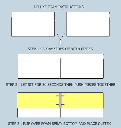
13 Page 13 TRAMPOLINE PAD INSTALLATION (FOR PREMIUM AND DELUXE PADS ONLY) 1. ORGANIZE YOUR PADDING AND PREP FOR INSTALLATION Layout foam pieces to figure out which pieces go where, refer to TRAMPOLINE PAD INSTALLATION diagram (page 15). Generally, if one side of your trampoline is longer than 8 you will be required to glue two pieces of equal length together to make a complete pad. For instance if you have a 7 x 14 trampoline, you will be required to glue together (2) 7 sections in order to make the 14 pad. The 7 section would come as a whole complete piece since it is under GLUE THE LONG SIDE PADDING TOGETHER Once your pads have been organized for where they will be positioned around the trampoline: A - Spray glue both ends of the 2 pads where they will attach to each other, in the middle. (If you don t understand this step, re-read step number 1 and/or see diagram on page 15). B - Let sit until tacky for 1-2 minutes. C - Put both pieces together and allow to sit for 30 minutes. 3. INSERT FOAM INTO VINYL COVERS After the glued-together foam pieces have sat for 30 minutes or more, stuff pads into their vinyl covers. If you have premium padding 9 thick then proceed to step 5. If you have deluxe then go to step INSERT 1.25 THICK CLOSED CELL FOAM SPACERS A - Stuff the included 1.25 thick, closed cell foam into the vinyl padding covers, underneath the larger foam pieces, and toward the outer edge (zipper side) of padding (Closed Cell Foam should not be under the nose or slanted portion of the padding). B - Please be sure that closed cell foam is placed under all the deluxe padding and zip closed. 5. ALIGN PADDING AND SECURE WITH VELCRO STRAPS. A - Align your padding around the trampoline. B - Place velcro straps onto corner and side bags where they meet. You will notice that there will be an area where velcro is already sewn onto the vinyl bags. TIP: You will want to put the notched velcro on first and then place the non-notched piece on second. (See diagram on page 16)


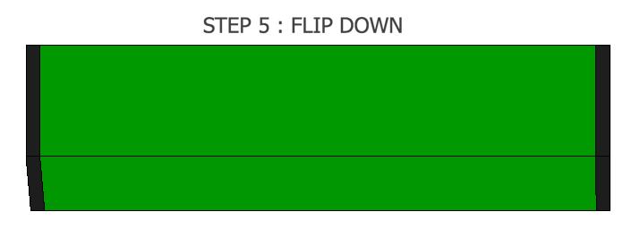
14 Page 14 TRAMPOLINE PAD INSTALLATION 1. ORGANIZE YOUR PADDING AND PREP FOR INSTALLATION Layout pads to figure out their position. (Refer to TRAMPOLINE PAD INSTALLATION diagram on page 15). 2. MOVE INTO POSITION Move pads into position, so pads are snug to each other and cover springs. Make sure anchoring flaps are positioned to the outside, and tucked neatly underneath outer edge of pads. 3. SECURE WITH LANDSCAPE SPIKES THROUGH FLAPS. Carefully hinge up a pad, making sure that the anchoring flap stays in position, and anchor in place, using landscaping spikes. Drive a spike through anchoring flap every 36 inches. After anchoring in position, flip pad back down into position. 4. In diagram spring pad covers are shown these steps of installing pads will also work on Deluxe and Premium models.
15 OLETEX INSTRUCTIONS Page 15
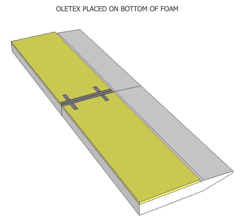
 Deluxe pad sets will include sheets of 1.25 Oletex foam.")
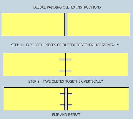
16 Page 16 TRAMPOLINE FOAM INSTALLATION 14 X 14 FOAM CONTENTS: 4 : 48 X 48 CORNERS (ALREADY FITTED) 8 : 84 LONG SIDE PIECE (2) side pieces of foam will need to be glued together then allowed to sit for 30 minutes before stuffing in cover. Closed Cell Foam (Not included with Premium Foam) Deluxe pad sets will include sheets of 1.25 Oletex foam. These are to be added to the bottom of the 6 foam so that they are closer to the ground. They will be positioned toward the zipper side of the bag and as close to the edge as possible so that they are not underneath the nose of the pads. (2) end pieces of foam will need to be glued together then allowed to sit for 30 minuts before stuffing in cover.
17 Page 17 SECURING YOUR PADDING WITH VELCRO STRAPS (APPLIES TO PREMIUM AND DELUXE) NOTE: There are (4) straight straps and (2) left side notched straps and (2) right side notched straps. STRAIGHT VELCRO STRAP - INSTALL 1ST Start with the strap attached to outside edge of trampoline towards the bottom where the padding meets the ground. Continue attaching velcro strap towards the trampoline bed and wrap excess underneath the nose (slanted portion of padding) of the trampoline. LEFT SIDE VELCRO STRAP - INSTALL 2ND Notched piece will slide around the nose and over the top and bottom of trampoline pad- tuck bottom portion under the pad toward the outside edge of the trampoline - wrap top portion over the top of the pads towards the outside perimeter of the trampoline and down the outside edge of the pads LEFT SIDE VELCRO STRAP INSTALL 2ND Same as above instructions 4 5 STRAIGHT VELCRO STRAP INSTALL 1ST Same as above instructions 6
18 Page 18 CONGRATULATIONS! YOU HAVE COMPLETED YOUR INSTALL BELOW IS 14 X14 TRAMPOLINE PLEASE NOTE : RED CLIPS SHOW AT EDGE OF PADDING THIS IS SO PADS DO NOT RUB ON STRINGS AND BREAK THEM
10 x 12 home air pro. VISIT LINK BELOW FOR INSTALL VIDEO
 in-ground installation instructions & user guide 10 x 12 home air pro VISIT LINK BELOW FOR INSTALL VIDEO https://www.maxairtrampolines.com/pages/support-information-videos Page 2 TABLE OF CONTENTS Materials,
7 x 14 flybed tramp. VISIT LINK BELOW FOR INSTALL VIDEO
 in-ground installation instructions & user guide 7 x 14 flybed tramp VISIT LINK BELOW FOR INSTALL VIDEO https://www.maxairtrampolines.com/pages/support-information-videos Page 2 TABLE OF CONTENTS Materials,
Chapter 1. Beam and Sill Plates
 Chapter 1. Beam and Sill Plates 1.1 ESTABLISHING SQUARE SILL PLATE CHALK LINES 1.2 INSTALLING TREATED SILL PLATES 1.3 INSTALLING LAMINATE BEAM Tools needed by volunteers: Hammer Nail apron Tape measure
U-bass Kit Assembly Instructions
 U-bass Kit Assembly Instructions Compiled by playubass.com This guide is built from the instructions found here: http://kalabrand.com/ubass-kit/index.html Tools Needed 5/8 (16 mm) Wrench 7/16 (~11 mm)
Flex Fence Instruction Manual
 The Safer Stronger Smarter Choice Flex Fence Instruction Manual Table of contents 2 3 4 4 5 5 6 7 8 10 10 11 11 12 13 13 15 18 18 19 20 22 Table of contents Supplies, tools and equipment Introduction Laying
MKPLAY VAULT MINI TRAMPOLINE SERIES
 MKPLAY VAULT MINI TRAMPOLINE SERIES 55 INCH (4.5FT) TRAMPOLINE WITH SAFETY NET ENCLOSURE Weight Limit 100lbs (45kg) Person Limit 1 Persons Age Limit 3-6 years 1 TABLE OF CONTENTS Parts List Trampoline
woodworkersjournal.com MATERIAL LIST
 MATERIAL LIST T x W x L 1 Legs (2) 1 1 2" x 3 1 2" x 36 7 16" 2 End Uprights (2) 1 1 2" x 3 1 2" x 32 1 2" 3 Stringers (4) 1 1 2" x 3 1 2" x 42" 4 Top Cladding, Long (2) 3/4" x 7 1 4" x 65 3 4" 5 Side
Side Mount INSTRUCTION BOOKLET #C122 BED STYLE: PARK CITY
 Side Mount BED STYLE: PARK CITY INSTRUCTION BOOKLET #C1 WARNING! ALL MURPHY/WALLBED SYSTEMS CONTAIN STORED ENERGY. FAILURE TO USE AND FOLLOW THESE INSTRUCTIONS DURING THE INSTALLATION PROCESS COULD RESULT
10x10 Trellis Pergola
 0x0 Trellis Pergola ASSEMBLY GUIDE Ver.0-7 Table of Contents PAGE Introduction & Overview...................................................... Pergola Materials Overview..............................................................
RAMPAGE P R O D U C T S. INSTALLATION INSTRUCTIONS BRONCO ZIPPER FASTRACK TOP PART #984xx BRONCO TOOLS REQUIRED
 RAMPAGE P R O D U C T S 84 (+/- 1/4 ) INSTALLATION INSTRUCTIONS BRONCO ZIPPER FASTRACK TOP PART #984xx BRONCO 1966-1977 TOOLS REQUIRED 3/8 WRENCH 7/16 WRENCH ½ WRENCH #2 PHILLIPS SCREWDRIVER 1/8 DRILL
The following instructions will guide you through the installation of your new vinyl railing.
 Installation Guide St. James Vinyl T-Rail Tools Required Protective eye glasses 3/8 x 3 Concrete Anchors/Fasteners (for Tape measure concrete installations) Variable speed drill/screwdriver Philips Driver
Laney chair. assembly instructions
 Laney chair assembly instructions Smooth & Wrinkle-Free Fabric Covers: In addition to these printed instructions, you may want to watch our beauty tips videos on the customer service page of our website.
ASSEMBLY GUIDE. Barcelona Pergola. 12 X16 (365CMx487CM) VER /01/19
 VER /01/19") ASSEMBLY GUIDE Barcelona Pergola 12 X16 (365CMx487CM) VER 1.9 04/01/19 GETTING STARTED First off, allow us to say thank you for the investment you have made in our fine pergola. This pergola is designed
ASSEMBLY GUIDE Barcelona Pergola 12 X16 (365CMx487CM) VER 1.9 04/01/19 GETTING STARTED First off, allow us to say thank you for the investment you have made in our fine pergola. This pergola is designed
Plastibeton Trench System. Installation Packet
 Plastibeton Trench System Installation Packet Plastibeton Installation Guide This Installation Guide is intended to assist in the preparation and installation of Plastibeton products manufactured by Oldcastle
6 1/2 x 6 1/2 Wood Grain Flat Top Pergola
 / x / Wood Grain Flat Top Pergola A S S E M B LY G U I D E Models: Lakewood OPTIONAL ACCESSORY Bolt Down Bracket Kit V.-09 Ta b l e o f Co n t e n t s The PAGE Introduction & Overview.......................................................
Low/High Tunnel Greenhouse Plans
 Low/High Tunnel Greenhouse Plans Tools Needed (See the complete list of Greenhouse Tools) Hacksaw or Reciprocating Saw Socket Wrench, Adjustable Wrench or Nut Drivers Electric Drill with Drill Bits Sledge
Ray chair & half. assembly instructions
 Ray chair & half assembly instructions Smooth & Wrinkle-Free Fabric Covers: In addition to these printed instructions, you may want to watch our beauty tips videos on the customer service page of our website.
Ledgewood Farm greenhouse. construction
 Ledgewood Farm greenhouse How do I Start? construction to I m Finished! Post layout The string will be 7 above the ground and the posts will be driven until the proper drill hole is at the string. Spacing
 INSTRUCTION BOOKLET #C10 Watch step by step installation instructions at: https://www.wallbedsbywilding.com/wallbed-installation-studio-series/ WARNING! ALL MURPHY/WALLBED SYSTEMS CONTAIN STORED ENERGY.
CertainTeed INSTALLATION GUIDE SIMTEK FENCE PRODUCTS. Fence Installation Guide 3', 4' & 6' High
 CertainTeed INSTALLATION GUIDE SIMTEK FENCE PRODUCTS Fence Installation Guide 3', 4' & 6' High INSTALLATION GUIDE These instructions are designed to assist both professional installers and do-it-yourselfers
Deck Mount Installation with Bench
 Deck Mount Installation with Bench 1. Mark track with square. 2. Cut tracks with saw. 3. Drill ¼ hole (if needed.) 4. Countersink track. 5. Countersink all track 6. File all track ends. ends. 7. Lay out
Sort 4 (four) 2x6x12 pieces and cut to 126 1/2" for a total of 4 (four) 126 1/2" pieces.
 2x6x12 pieces and cut to 126 1/2 for a total of 4 (four) 126 1/2 pieces.") # Materials: Quantity Each: Total Quantity: xx8 6 x6x8 1 x6x1 1 TIPS FOR SUCCESSFUL PREP WORK: Before starting, carefully read through the entire instruction sheet. Refer to the material list to the left
# Materials: Quantity Each: Total Quantity: xx8 6 x6x8 1 x6x1 1 TIPS FOR SUCCESSFUL PREP WORK: Before starting, carefully read through the entire instruction sheet. Refer to the material list to the left
Tux sofa. assembly instructions
 Tux sofa assembly instructions Smooth & Wrinkle-Free Fabric Covers: In addition to these printed instructions, you may want to watch our beauty tips videos on the customer service page of our website.
PORTA TRAK OWNERS MANUAL
 PORTA TRAK OWNERS MANUAL Table of Contents: I. Rail and Frame Parts List Please read the instructions thoroughly before setting up the Porta Trak. Carefully follow how to spring the bed step by step. II.
Tux chair & half. assembly instructions
 Tux chair & half assembly instructions Smooth & Wrinkle-Free Fabric Covers: In addition to these printed instructions, you may want to watch our beauty tips videos on the customer service page of our website.
6 1/2 x 6 1/2 Wood Grain Flat Top Pergola
 / x / Wood Grain Flat Top Pergola A S S E M B LY G U I D E Models: Lakewood OPTIONAL ACCESSORY Bolt Down Bracket Kit V.- Ta b l e o f Co n t e n t s The PAGE Introduction & Overview.......................................................
The Festival Assembly Instructions
 The Festival Assembly Instructions Toll Free: 866.768.8465 Hours: 9-5 Monday-Friday EST www.homeplacestructures.com Package ships as shown CONTACT INFORMATION: HomePlace Structures 301 Commerce Drive New
https://www.wallbedsbywilding.com/wallbed-installation-studio-series/
 For Wallbed models: KING SIZE INSTRUCTION BOOKLET #C1 Watch step by step installation instructions at: https://www.wallbedsbywilding.com/wallbed-installation-studio-series/ WARNING! ALL MURPHY/WALLBED
INSTRUCTION BOOKLET #C21. For Wallbed models: KING SIZE
 For Wallbed models: KING SIZE INSTRUCTION BOOKLET #C1 WARNING! ALL MURPHY/WALLBED SYSTEMS CONTAIN STORED ENERGY. FAILURE TO USE AND FOLLOW THESE INSTRUCTIONS DURING THE INSTALLATION PROCESS COULD RESULT
 INSTRUCTION BOOKLET #C0 Watch step by step installation instructions at: https://www.wallbedsbywilding.com/wallbed-installation-studio-series/ WARNING! ALL MURPHY/WALLBED SYSTEMS CONTAIN STORED ENERGY.
Laney loveseat. assembly instructions
 Laney loveseat assembly instructions Smooth & Wrinkle-Free Fabric Covers: In addition to these printed instructions, you may want to watch our beauty tips videos on the customer service page of our website.
Congratulations! Your dog is going to love you!
 DIY INSTRUCTIONS Congratulations! Your dog is going to love you! Thank you for ordering your non-electric dog fence kit from Pet Playgrounds. In less than a day you will have your very own personal dog
Installation Manual For ToddPod Outdoor Shower Enclosures
 Installation Manual For ToddPod Outdoor Shower Enclosures Contact us at 888-545-9763 or email us at office@toddpod.com with any questions during the installation process. Our service team is available
Plans. Easy-to-Build Full-size Deluxe Murphy Bed Plan. For more plans, tools and hardware visit rockler.com
 Easy-to-Build Full-size Deluxe Murphy Bed Plan Build a full-size Deluxe Murphy Bed complete with decorative molding and matching side cabinets! Plans For more plans, tools and hardware visit rockler.com
6 1/2 x 6 1/2 Flat Top Pergola
 6 / x 6 / Flat Top Pergola A S S E M B L Y G U I D E Models: Portland, Liberty O P T I O N A L A C C E S S O R Y Bolt Down Bracket Kit V.-0506 Ta b l e o f Co n t e n t s PAGE The Introduction & Overview......................................................
Equilibrium. Conference Table. Installation Instruction. Revision B 11/07/16
 Equilibrium Conference Table Installation Instruction Revision B 11/07/16 Equilibrium End User Agreement Enwork Equilibrium table bases must be installed directly onto a four inch minimum thickness concrete
*Patent Pending. *Trademarked. Series II. Glass Conversion Kit. (888) One-Products (888)
 One-Products (888)") *Patent Pending *Trademarked Series II Glass Conversion Kit www.onepieceproducts.com (888) One-Products (888) 663-7763 Installation Manual Full One Piece Door Glass Conversion Kit Series II 1967-1972 Chevy
*Patent Pending *Trademarked Series II Glass Conversion Kit www.onepieceproducts.com (888) One-Products (888) 663-7763 Installation Manual Full One Piece Door Glass Conversion Kit Series II 1967-1972 Chevy
Installation Guide. Capped Cellular PVC Fencing. Table of Contents. Storage and Handling Tools Needed Fence Layout and Locating Posts
 Capped Cellular PVC Fencing Installation Guide Table of Contents Storage and Handling Tools Needed Fence Layout and Locating Posts Installation instructions 4 x 4 Over Sleeve Post - 3.5 Rail Privacy Shadowbox
Plastibeton Trench System. Installation Packet
 Plastibeton Trench System Installation Packet Plastibeton Installation Guide This Installation Guide is intended to assist in the preparation and installation of Plastibeton products manufactured by Oldcastle
WILDING WALLBEDS INSTALLATION INSTRUCTION Side Mount
 WILDING WALLBEDS INSTALLATION INSTRUCTION Side Mount For Wallbed models: Do-It-Yourself Insturction booklet C92 WARNING! ALL MURPHY/WALLBED SYSTEMS CONTAIN STORED ENERGY. FAILURE TO USE AND FOLLOW THESE
Best Barns USA. Assembly Book. 12'x 16' the Millcreek. Revised September 19, 2017
 Assembly Book Best Barns USA Revised September 19, 2017 the Millcreek 12'x 16' Manufactured by Reynolds Building Systems, Inc 205 Arlington Drive Greenville, PA 16125 This manual is copyrighted Under the
6 1/2 x 6 1/2 Wood Grain Flat Top Pergola
 6 / x 6 / Wood Grain Flat Top Pergola A S S E M B LY G U I D E Models: Lakewood OPTIONAL ACCESSORY Bolt Down Bracket Kit Ver /AUG/0 Ta b l e o f Co n t e n t s PAGE The 6.5 x 6.5 Wo o d Grain Flat Top
The following instructions will guide you through the installation of your new vinyl railing stair kit.
 Installation Guide Vinyl Standard Stair Railing Tools Required Protective eye glasses Tape measure Variable speed drill/screwdriver Rotary hammer or hammer drill and masonry percussion bit recommended
Best Barns USA Assembly Book
 Best Barns USA Assembly Book Revised September 19, 2017 the Millcreek 12'x 20' Manufactured by Reynolds Building Systems, Inc 205 Arlington Drive Greenville, PA 16125 This manual is copyrighted Under the
CONTINUED. TABLE TOPS: 1. Sort one 2x6x8 piece from your lumber. 2. Measure and mark two 48 pieces from each, then cut.
 # Materials: Quantity Each: Total Quantity: x4x8 7 x6x8 1 TIPS FOR SUCCESSFUL PREP WORK: Before starting, carefully read through the entire instruction sheet. Refer to the material list to the left and
It can be either a 2½ seater bench seat (2 adult and a kid), or a 5 seater picnic table.
, or a 5 seater picnic table.") Page 1 Folding picnic table in both bench-seat and picnic table mode Introduction Description A single bench seat that can be changed into a picnic table with ease. This 'Bench come Picnic Table' is ideal
Page 1 Folding picnic table in both bench-seat and picnic table mode Introduction Description A single bench seat that can be changed into a picnic table with ease. This 'Bench come Picnic Table' is ideal
ALIEN ENCLOSURES GM A-BODY Trunk Panel Kit instructions
 ALIEN ENCLOSURES 68-72 GM A-BODY Trunk Panel Kit instructions TYPICAL TOOLS & MATERIALS NEEDED FOR UPHOLSTERED KITS 2 Yards of Main Panel Material 1.5 Yards of Backer Material 3 yards of foam backing material
Installation Instructions for Vista Air Vertically Folding Walls
 Installation Instructions for Vista Air Vertically Folding Walls Use these instructions in conjunction with your shop drawings to see the specifics that are particular to the model you are installing.
Dura-Lock Roof System
 DLR-14 Dura-Lock Roof System Assembly and Installation Instructions Read the instructions before starting the job. They explain the steps required to produce a finished product that will meet factory specifications.
CONTINUED. BACK & SEAT RAILS: 1. Sort three (3) 2x2x8 pieces. 2. Measure and cut one (1) 61 length from each piece.
 2x2x8 pieces. 2. Measure and cut one (1) 61 length from each piece.") # Materials: Quantity Each: Total Quantity: 2x2x8 6 2x4x8 9 4x4x8 2 4x6x8 1 TIPS FOR SUCCESSFUL PREP WORK: Before starting, carefully read through the entire instruction sheet. Refer to the material list
# Materials: Quantity Each: Total Quantity: 2x2x8 6 2x4x8 9 4x4x8 2 4x6x8 1 TIPS FOR SUCCESSFUL PREP WORK: Before starting, carefully read through the entire instruction sheet. Refer to the material list
TRADITIONAL & SCALLOP PICKET INSTALLATION INSTRUCTIONS
 TRADITIONAL & SCALLOP PICKET 1 WHAT YOU LL NEED TO INSTALL POWER AUGER OR POST HOLE DIGGER(CLAMSHELLS) SHOVEL DIGGING BAR (OPTIONAL) BRIGHT COLORED SPRAY PAINT STRING LINE STAKES AND LEVEL CORDLESS OR
southpaw enterprises, inc.
 southpaw enterprises, inc. Instruction Sheet C-STAND 7100 Store these instructions in a safe place or with the enclosed maintenance checklist Take time to familiarize yourself with the use and maintenance
PRO-RIB FENCE PANELS INSTALLATION GUIDELINES. Virtually Maintenance Free Available in 24 Colors Custom Heights Available by the Inch
 PRO-RIB FENCE PANELS INSTALLATION GUIDELINES Virtually Maintenance Free Available in 24 Colors Custom Heights Available by the Inch www.midwestmanufacturing.com Page 2 TOOLS NEEDED Measuring Tape Drill
 For Wallbed models: KING SIZE INSTRUCTION BOOKLET #C1 Watch step by step installation instructions at: https://www.wallbedsbywilding.com/wallbed-installation-studio-series/ WARNING! ALL MURPHY/WALLBED
10x10 Trellis Pergola
 0x0 Trellis Pergola ASSEMBLY GUIDE Ver.-007 Table of Contents PAGE 0x0 Trellis Pergola Introduction & Overview...................................................... Pergola Materials Overview..............................................................
Design, Build and Upholster a Custom Chair
 Rowley How-To Guide Design, Build and Upholster a Custom Chair Sometimes the perfect furniture piece to complete a room may not exist. In this case, why not design, build and upholster to your own specifications,
8 x 8 Flat Top Pergola
 A B C ASSEMBLY GUIDE Models: Mirage OPTIONAL ACCESSORIES A) Bolt Down Bracket Kit ( for Pergola) B) Tall Base Molding C) Short Base Molding Ver 0.-067 Table of Co n t e n t s PAGE Introduction & Overview......................................................
SEATS (middle and front row): 1. Sort six (6) 2x6x10 pieces. 2. Measure and cut one (1) 72 length and one (1) 48 length from each piece.
: 1. Sort six (6) 2x6x10 pieces. 2. Measure and cut one (1) 72 length and one (1) 48 length from each piece.") # Materials: Quantity Each: Total Quantity: 2x6x8 6 2x6x10 6 2x4x8 4 4x4x8 7 TIPS FOR SUCCESSFUL PREP WORK: Before starting, carefully read through the entire instruction sheet. Refer to the material list
# Materials: Quantity Each: Total Quantity: 2x6x8 6 2x6x10 6 2x4x8 4 4x4x8 7 TIPS FOR SUCCESSFUL PREP WORK: Before starting, carefully read through the entire instruction sheet. Refer to the material list
12 x 24 Flat Top Pergola
 A S S E M B LY G U I D E OPTIONAL ACCESSORIES: Bolt Down Bracket Kit Privacy Wall (6 for Pergola) Pergola Planter Ver.-75 Ta b l e o f Co n t e n t s PAGE Introduction & Overview......................................................
SHADOWBOX INSTALLATION FOR: Standard 6 H x 8 W Shadowbox Fence 5 x 5 Routed Posts Dog Ear or Straight-Edge Pickets 1.75 x 3.5 Rail
 SHADOWBOX INSTALLATION FOR: Standard 6 H x 8 W Shadowbox Fence 5 x 5 Routed Posts Dog Ear or Straight-Edge Pickets 1.75 x 3.5 Rail Storage and Handling Fence Preparation and Layout Locate and Set Posts
Ranch Rail Vinyl Fence
 Ranch Rail Vinyl Fence INSTALLATION INSTRUCTIONS These instructions are to be used as general guidelines for the installation of your vinyl fence under normal installation conditions. Local conditions
Double Beam Freestanding Pergola Installation Guide
 Double Beam Freestanding Pergola Installation Guide Patent Pending. Copyright 2011 USAVinyl, LLC - All Rights Reserved The information contained in these instructions are proprietary to USAVinyl, LLC and
RANCH RAIL FENCE INSTALLATION INSTRUCTIONS
 1 WHAT YOU LL NEED TO INSTALL POWER AUGER OR POST HOLE DIGGER(CLAMSHELLS) SHOVEL DIGGING BAR (OPTIONAL) BRIGHT COLORED SPRAY PAINT STRING LINE STAKES AND LEVEL CORDLESS OR POWER DRILL WITH DRILL AND SCREW
Belham Living Harbor Bay Pergola
 Belham Living Harbor Bay Pergola A S S E M B LY G U I D E OPTIONAL ACCESSORY Bolt Down Bracket Kit Models: Ver.0-08065 Belham Living Harbor Bay Ta b l e o f Co n t e n t s B elham Living Harbor Bay Pergola
TS-20KD-1010 LOW PROFILE CARGO SCALE INSTALLATION GUIDE
 TS-20KD-1010 LOW PROFILE CARGO SCALE INSTALLATION GUIDE Triner Scale & Mfg. Co., Inc. 8411 Hacks Cross Rd. Olive Branch, MS 38654 Phone: 800-238-0152 Fax: 662-809-2386 Description The Triner Scale Model
A MULTI-PURPOSE LOFT THAT CAN BE USED FOR SLEEPING, STORAGE, AND FREEING UP SPACE (Supports 200 lbs max) DIFFICULTY: 6/10
 DIFFICULTY: 6/10") A MULTI-PURPOSE LOFT THAT CAN BE USED FOR SLEEPING, STORAGE, AND FREEING UP SPACE (Supports 200 lbs max) DIFFICULTY: 6/10 CAUTION The instructions are only a guide, and should be followed by individuals
A MULTI-PURPOSE LOFT THAT CAN BE USED FOR SLEEPING, STORAGE, AND FREEING UP SPACE (Supports 200 lbs max) DIFFICULTY: 6/10 CAUTION The instructions are only a guide, and should be followed by individuals
Front Vise 70G G08.02
 Front Vise 70G08.01 70G08.02 The following instructions guide you through the installation of either the Regular Front Vise (70G08.01) or the Large Front Vise (70G08.02). The first step is to determine
16ft Polytunnel Assembly Instructions
 CONTENTS Section Page 1. FOUNDATION TUBES: Option A Ground Anchor Plates 3 2. FOUNDATION TUBES: Option B Concreted Foundation Tubes 5 3. STEEL FRAME ASSEMBLY & INSTALLATION 6 4. CROP BARS 8 5. TIMBER END
Modular ottoman. assembly instructions
 Modular ottoman assembly instructions Smooth & Wrinkle-Free Fabric Covers: In addition to these printed instructions, you may want to watch our beauty tips videos on the customer service page of our website.
ALIEN ENCLOSURES CAMARO AND FIREBIRD Trunk Panel Kit Instructions
 ALIEN ENCLOSURES 67-69 CAMARO AND FIREBIRD Trunk Panel Kit Instructions TYPICAL TOOLS & MATERIALS NEEDED FOR UPHOLSTERY 2 Yards of Main Panel Material 1.5 Yards of Backer Material 3 yards of foam backing
8x8 Spa Breeze Pergola Assembly Manual Outdoor Living Today
 8x8 Spa Breeze Pergola Assembly Manual Outdoor Living Today Revision 3. Feb 18th/2015 Note: Post Mounting Hardware is NOT included in this kit. Please confirm with your local building permit office to
MantelMount. TM1A Installation Instructions IMPORTANT SAFETY INSTRUCTIONS - SAVE THESE INSTRUCTIONS
 MantelMount TMA Installation Instructions IMPORTANT SAFETY INSTRUCTIONS - SAVE THESE INSTRUCTIONS TM Thank you for choosing the MantelMount television wall mount. Please read this entire manual before
12, 14 & 16 Wide Enclosure Assembly Guide
 www.rmfiberglass.com 12, 14 & 16 Wide Enclosure Assembly Guide RM Products Ltd 1-800-363-0867 www.rmfiberglass.com Table of Contents 1. Handling and Storage page 3 to 5 2. Parts and Tools List page 7 3.
Installation Instructions for. Before You Begin TOOLS REQUIRED
 Composite Railing System STEP-BY-STEP Installation Instructions for Spectrum Composite Railing Virtually maintenance free 20-year warranty EverNew Spectrum Railing system is designed to work with a number
Assembly Instructions
 10' and 12' Octagon Cedar Gazebo Assembly Instructions Toll Free: 866.768.8465 Hours: 9-5 Monday-Friday EST www.homeplacestructures.com Package ships as shown revised 06/20/09 Cedar Gazebo Assembly Instructions
Building Instructions
 Building Instructions Tools Required Tape measure Straight edge Pencil/pen Jigsaw Table Saw Circular Saw Electric drill 1 Hole saw bit Saw horses/table Protractor Staple gun Caulk gun Paint brush Wrenches
UNIVERSAL PANEL AND GATE
 PVC Fencing / Residential Style UNIVERSAL PANEL AND GATE INSTALLATION INSTRUCTIONS Fencing Without Boundaries TM 1 BEFORE YOU START, IT S IMPORTANT TO CHECK......That fence footings do not exceed legally
How to build a Ram for Challenge E: Twist-O-Rama
 How to build a Ram for Challenge E: Twist-O-Rama Notes The Ram is like the Structure Tester it is not Interference for a Team Manager or other non-team members to build it. Construction time is approximately
FENCE INSTALLATION GUIDE 8 HIGH WALLS
 FENCE INSTALLATION GUIDE 8 HIGH WALLS 1.866.648.9336 www.simtekfence.com INSTALLATION GUIDE These instructions are designed to assist both professional installers and do-it-yourselfers of SimTek decorative
Monroe sofa. assembly instructions
 Monroe sofa assembly instructions Smooth & Wrinkle-Free Fabric Covers: In addition to these printed instructions, you may want to watch our beauty tips videos on the customer service page of our website.
2.9 WINDOW & DOOR BUCKS
 2.9 WINDOW & DOOR BUCKS Bucks provide attachment surfaces for windows and doors while holding back concrete from these openings during concrete placement. Mark the center and edges of openings as you place
12 x 12 Flat Top Pergola
 x Flat Top Pergola A S S E M B LY G U I D E Model: Freemont OPTIONAL ACCESSORY Bolt Down Bracket Kit ( for Pergola) Ver /NOV 00 AI-BP0-0- Ta b l e o f Co n t e n t s PAGE x Flat Top Pergola Introduction
LOFT DOOR HANGER BARN DOORS & HARDWARE. Hardware Installation Instructions. Page
 LOFT DOOR HANGER Page 1 Specifications 2 7/16" 3/8" 1-1/2 1-3/4 Ø3 3 7/8" 11-1/16 Page 2 Parts and Tools Tools Needed Tape Measure Pencil Drill with 1/8, 1/4 and 3/8 bits, 1 spade bit and Phillips bit
TUMBL TRAK OWNERS MANUAL
 TUMBL TRAK OWNERS MANUAL Table of Contents: I. Assembly Instructions for the Tumbl Trak 1. Frame Assembly 2. Springing the Bed 3. Using The Spring Tool 4. Attaching the Frame Pads & End Caps A. After Assembly
INSTRUCTION BOOKLET #34. For Wallbed models: KING SIZE SIERRA WITH STORAGE HEADBOARD
 For Wallbed models: KING SIZE SIERRA WITH STORAGE HEADBOARD INSTRUCTION BOOKLET #34 WARNING! ALL MURPHY/WALLBED SYSTEMS CONTAIN STORED ENERGY. FAILURE TO USE AND FOLLOW THESE INSTRUCTIONS DURING THE INSTALLATION
PRIVACY FENCE WITH SCALLOPED PICKET INSTALL INSTRUCTIONS
 PRIVACY FENCE WITH SCALLOPED PICKET INSTALL INSTRUCTIONS These instructions are to be used as general guidelines for the installation of your vinyl fence under normal installation conditions. Local conditions
ClearSpan PolyMax Windbreak Wall
 ClearSpan PolyMax Windbreak Wall Photo may show a different but similar model. 2007 ClearSpan All Rights Reserved. Reproduction is prohibited without permission. Revision date: February 2007ldg STK# DIMENSIONS
Best Barns USA Assembly Book
 Best Barns USA Assembly Book Revised February 4, 2016 the Millcreek-R 12'x 20' Manufactured by Reynolds Building Systems, Inc. 205 Arlington Drive Greenville, PA 16125 724-646-3775 This manual is copyrighted.
12 x 12 Flat Top Pergola
 x Flat Top Pergola Model: Regency, Roosevelt A S S E M B L Y G U I D E O P T I O N A L A C C E S S O R Y Bolt Down Bracket Kit ( for Pergola) Ver./MAR 0 Ta b l e o f Co n t e n t s PAGE x Flat Top Pergola
12 x 12 Flat Top Pergola
 x Flat Top Pergola Model: Freemont A S S E M B L Y G U I D E O P T I O N A L A C C E S S O R Y Bolt Down Bracket Kit ( for Pergola) Ver.-057 Ta b l e o f Co n t e n t s PAGE x Flat Top Pergola Introduction
OPTIONAL PARTS LIST: Installation Instructions VPS TRAMPOLINE PARTS LIST. Lower Frame Support Brace (8) Nuts, bolts, and washers (16 each)
 Nuts, bolts, and washers (16 each)") OPTIONAL PARTS LIST: **if you purchased a TDU Bundle system- you will also have a lower frame support box with the following parts included: Lower Frame Support Brace (8) Nuts, bolts, and washers (16 each)
OPTIONAL PARTS LIST: **if you purchased a TDU Bundle system- you will also have a lower frame support box with the following parts included: Lower Frame Support Brace (8) Nuts, bolts, and washers (16 each)
With Illustrations, Drawings & Step By Step Details. Click Here To Download 12,000 Shed Plans. 1 P a g e Download 12,000 More Shed Plans
 With Illustrations, Drawings & Step By Step Details Click Here To Download 12,000 Shed Plans 1 P a g e Download 12,000 More Shed Plans Table of Contents OVERVIEW... 3 MATERIALS & CUTTING LISTS... 4 DRAWINGS,
Ali sectional right. assembly instructions
 Ali sectional right assembly instructions Smooth & Wrinkle-Free Fabric Covers: In addition to these printed instructions, you may want to watch our beauty tips videos on the customer service page of our
Woodline USA Woodline Spacer Fence System
 Woodline USA Woodline Spacer Fence System MADE IN THE USA Includes: (1) ¼ Spacer Fence (1) 3/8 Spacer Fence (1) ½ Spacer Fence (1) Hardware Package (1) 3 Piece Brass bar set (2) Setup Blocks Visit Us Online
PRIVACY FENCE WITH LATTICE INSTALLATION INSTRUCTIONS
 PRIVACY FENCE WITH LATTICE INSTALLATION INSTRUCTIONS These instructions are to be used as general guidelines for the installation of your vinyl fence under normal installation conditions. Local conditions
Monroe loveseat. assembly instructions
 Monroe loveseat assembly instructions Smooth & Wrinkle-Free Fabric Covers: In addition to these printed instructions, you may want to watch our beauty tips videos on the customer service page of our website.
10 x 10 Flat Top Two Tone Pergola
 0 x 0 Flat Top Two Tone Pergola Models: Bordeaux ASSEMBLY GUIDE OPTIONAL ACCESSORIES Arch Kit System ( Arches) Privacy Fence Panel System ( Panels & Middle Post) Bolt Down Bracket Kit ( for Pergola) Ver.0-00
SE5a Wing Panels rev 1.0
 SE5a Wing Panels rev 1.0 The top and bottom wings are different. They might look the same but the bottom wing has one less rib and some rib spacing difference. This is due to where the wooden interplane
8 x 10 Timber-frame Garden Shed
 8 x 10 Timber-frame Garden Shed Includes: Step-By-Step Instructions, Complete Details & Materials Lists Timber-framing is a traditional building method that uses a simple framework of heavy timber posts
10 x 10 Arch Top Pergola
 0 x 0 Arch Top Pergola I N S T A L L A T I O N G U I D E O P T I O N A L A C C E S S O R I E S Privacy Fence Panel System ( Panels & Middle Post Included) Bolt Down Bracket Kit (Set of ) Additional Shade