How to Build a Structure Tester
|
|
|
- Candace Lawson
- 5 years ago
- Views:
Transcription
1 This material was originally authored by: Bill Allen, Orville Wright Williamson and Rick Rand It was revised on 10/17/02,12/17/03 and 11/30/04 by Victor Tom How to Build a Structure Tester Introduction First, ANYONE can build the Structure Tester. While some teams will elect to build their own Structure Tester, there is no danger of interference if the Team Manager (or a helpful parent) builds the Tester. In addition, it is perfectly acceptable to borrow a Structure Tester from somebody else. How the team TESTS their design is not part of their solution. However, since issues like weight placement (and weight order) ARE part of the team s solution, any help the team gets during testing should be of the passive lifting variety. Tournament officials will provide the Structure Tester and all weights used to test the Structure at the tournament. This means that teams may NOT elect to use their own Structure Tester and weights during the tournament. However, it is still a good idea for the team to get access to a tester (and weights) to test their practice Structures. It is recommended that weights with a 2 hole in the middle be used at tournaments. While these might be harder for teams to find for testing, it is a good idea to approach testing as much like it will done on tournament day as possible. For tournaments, it will be recommended that an assortment of 5 lb, 10 lb, 25 lb, 35 lb and 45 lb weights be available to total the expected maximum allowed in various combinations (this can change each year). Teams should be aware of the restrictions in this year s Challenge placed on the use of larger weights by younger teams when they use an Adult Assistant. With that introduction as background, there are 3 elements to a Structure Tester: 1. Presser Board 2. Tester Base 3. Safety Support This document attempts to provide a step-by-step approach to building each of those elements. There is no one correct way to build a Structure Tester so this document will try to offer a simple approach that will be easier to implement. Finally, the most important Structure Tester for the team to become familiar with is the one that will be used at their tournament. Last Revised: 11/26/13 Page 1
2 Building the Presser Board The Presser Board is 18 x 18, has a 2 diameter hole cut in the center and has a smooth, hard surface on the bottom. The Presser Board must be strong enough that it can transfer the load of the metal weights stacked on it to the Structure (and the Safety Support after the Structure breaks) without significant flexing. High quality 3/4 thick 5-ply hardwood plywood is probably the best material to use to build the structural body of the Presser Board. Hardwood plywood costs ~$50 per 4 x 8 sheet. Consequently, some teams may elect to use Medium Density Fiberboard (MDF) (which costs less than $20 per sheet) instead. Particle board or low-grade plywood should NOT be used. People with limited access to tools might want to buy a whole 4 x 8 sheet of hardwood plywood (or MDF) and have the lumberyard cut it into 18 squares. Cutting uniform 18 squares is VERY challenging without the right tools and many lumberyards will do it for free (or at least cheaply). A couple of 18 squares of tileboard (which is coated 1/8 MDF) or 1/8 High Density Fiberboard (HDF) are needed to provide the replaceable hard surfaces of the Structure Tester. Since these replaceable hard surfaces have to be replaced occasionally, it might be a good idea to buy a large sheet of this material and have the lumberyard cut that into 18 squares as well. For the current weight limits (no pipe extensions), the possibility of denting is highly reduced. Figures 1 and 2 provide crude side and top views of the Presser Board. Line two 18 squares of plywood up and clamp them together. Drill countersunk pilot holes through the two boards at various locations (see Figure 2). Unclamp the two boards and apply a wood glue liberally between them. Screw the two boards together and allow to dry. Fasten (small screws) an 18 square of tile board to the side opposite of the one where the screw heads are showing (see Figure 1). The hardest surface of the tileboard should be showing. Since the replaceable hard surface might have to be replaced, it would be a mistake to glue it to the rest of the Presser Board. The final action is to drill the 2 diameter hole through the center of the Presser Board. Using a pencil, draw lines between opposite corners on the tileboard surface. This makes a big X on the square. The center of the X is the center of the square. Drill a 2 hole through the middle of the Presser Board (see Figure 1). Drill from the tile board side to avoid damaging the tile board. You now have a completed Presser Board. Last Revised: 11/26/13 Page 2
3 18 square x ¾ thick boards are glued and screwed together How to Build a Structure Tester 2 hole cut in center of Presser Board 3/4 hardwood plywood or Medium Density Fiberboard Tileboard screwed on not glued 1/8 thick replaceable hard surface like tileboard or masonite Figure 1 Side view of Presser board screws 2 diameter hole Figure 2 top view of Presser board Last Revised: 11/26/13 Page 3
4 Building the Tester Base The Tester Base is basically built around a 1 (outer diameter) pipe floor flange. The floor flange is needed to hold the Safety Pole perpendicular to the surface of the Tester Base. The Safety Pole is a 27 long piece of 1 (OD) pipe threaded at one end and screwed into the floor flange. This length is highly dependent on the HEIGHT OF TESTER POLE as described in the challenge. There are sometimes two 12 pipe extensions that slide into the main Safety Pole (but not in 2004). Smaller 6 long 3/4 OD pipe sections should be epoxied into the safety pole extensions to allow seamless joints. Like the Presser Board, the Tester Base is 18 x 18. It also has a replaceable hard surface on the side facing the Structure. Figure 3 provides a crude exploded side view of the Tester Base. The loading on the Tester Base isn t as complex as the loading on the Presser Board (or Safety Supports). Consequently, MDF works almost as well as hardwood plywood for use in the Tester Base. To build the Tester Base, begin with a five 18 squares of plywood (MDF). For two boards, draw an X between the corners and cut holes slightly larger than the full diameter of the floor flange (2 nd and 3 rd board from bottom shown in Fig. 3). On the bottom board, mark a center X and position the floor flange in the middle and rotate the floor flange so the lines of the X are visible through the middle of the four attachment holes of the floor flange. Mark these locations and drill 5/16 holes through the MDF. These holes allow the countersunk screw bolts that will hold the floor flange to the bottom board. The floor flanges are rarely perfectly square so some shimming of the flange is usually needed to make the Safety Pole perfectly perpendicular to the Tester Base. The 2 nd and 3 rd board are fastened to this bottom board with deck screws. (see Fig. 3) Do a final tightening of the flange to the bottom board while checking squareness. For the 4 th and 5 th board, mark an X in the center and drill out a hole slightly larger than the iron pipe which fits in the flange. Attach these two boards to the rest of the tester base as shown in Fig. 3. One 18 square piece of replaceable hard surface like that used on the Presser Board will the final testing surface. A hole sllightly larger than the pipe needs to be drilled in the center of the hard surface, but it will not be attached until after the corner posts are fastened because the 2 x2 cutouts in each corner need to be measured and removed. It will be a good idea to cover anything protruding on the bottom surface with a heavy duty tape such as duct tape to protect floor. Last Revised: 11/26/13 Page 4
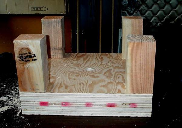
5 The pieces of the Tester Base don t have to be tightly bound together because gravity will do that as weight is applied. In fact, since it might be necessary to remove the floor flange from time to time, it would be a mistake to do anything that might make it hard to get access to the bolts holding it on. However, it makes sense to at least loosely tie all these sheets together (with a few screws) so they don t slip around. Hard Surface Tileboard Tacked on Safety Pole 1 diameter Threaded only at bottom Screws hold Plywood together Countersunk Hanging bolts Floor flange bolted to top of Second plywood sheet Figure 3 Side view of tester base showing 5 layers and position of flange It is easier to build from the bottom up (lower three pieces of plywood) with the flange in that assembly. Then screw the upper two sheets together and then bolt the upper two sheets to the Safety Supports (described below) with lag bolts. Then take the upper and lower assemblies and screw those together with 2 1/2 inch screws. Building the Safety Support 4 x 4 Corner Supports that bolt into Tester Base The key thing in building a Safety Support is that it must be strong enough to prevent the Presser Board and weights from falling all the way to the Tester Base when the Structure fails. The goal is to construct the Safety Support so it supports the Presser Board about 7 above the Tester Base. This limits the fall to 1 3 (which is reasonably safe). The stack of weights can be twisting (or moving laterally) as it falls, so the Safety Support must be robust enough to support these loads as well. Last Revised: 11/26/13 Page 5
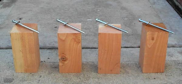
6 The simplest method for providing a Safety Support is to use the old style 4 x 4 corner supports (see Figure 3). The biggest advantage of this approach is simplicity of construction. The construction process is as follows: 1. Cut four 7 1/8 inch long pieces of 4 x Temporarily secure these 4 x 4 corner supports extending upwards from the corners of the tester base (without the masonite or tile board attached). 3. Turn the tester base over so that the upper assembly (two plywood sheets) is resting on the four corner supports. Drill 1/x diameter holes (the width of the lag bolt shaft) all the way through the base and 2 into the corner supports. Drill a 1 diameter countersink hole halfway into the base so that the lag bolt heads are well countersunk into the base. Use two bolts for each support for extra rigidity. 4. Insert the lag bolts and tighten with a ratchet wrench. 5. After support columns are in place, join the upper and lower assemblies together with long screws (already described above). 6. After the assembly is all together, you can then measure the 4x4 cutouts in each corner for the hard replaceable testing surface. 7. Fasten the hard testing surface to the tester base with small countersunk screws, far from the pole. Building and attaching the Safety Shields Four approximately 9 x 18 pieces of 1/16 thick Plexiglas or Lexan should be cut to act as Safety Shields. Depending on the design of the Safety Support, these could actually be quite a bit smaller. Team members involved in weight placement are required to wear Safety goggles this year. This is because it the bridges will extend beyond the main tester. For the remaining two sides, safety shields should be used. The easiest way to attach safety shields is to use self-sticking velcro. Apply 1 square sections in each of the four corners of the plexiglas, remove the other sticky side and press the plexiglass directly to the support posts in the position that is required. Keep the top edge of the plexiglass just below the tops of the support posts. Apply a vinyl tape to the top edge of the shields to protect fingers. Extension poles are made by gluing 6 long 3/4 OD metal rods (or wooden dowels) into ~12 long pieces of 1 metal pipe. (When you buy the black iron pipe, ask the store to cut a 24 length and two 12 lengths and thread only one end of the 27 length). About 3 of the rod should extend out of the pipe. The inside diameter of the pipe is slightly larger than 3/4 so some care needs to be exercised to make sure extension pole fits squarely into the Safety Pole. Metal tape (used for gutter repairs) can be used to build-up the diameter of the pipe extension so that it fits snuggly into the pipe below. Last Revised: 11/26/13 Page 6


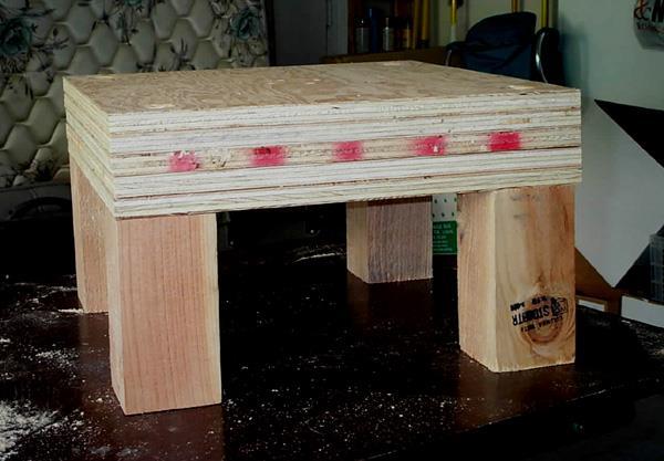
7 For DIsigning Bridges two support blocks 18 long made out of the 4x4 posts need to be cut and built up with wood strips to provide a support platform 1 above the surface of the tester base. These blocks provide the bridge base. When you re all done, spray paint the tester to give it a nice finish (Orville suggests auto enamel to give it that hard finish). Paste a DI logo on for a professional look at tournaments. Figure 5 Views of completed tester base and presser board with weights Last Revised: 11/26/13 Page 7


8 Supplies: Last Revised: 11/26/13 Page 8


9 Views of Tester during Construction: Last Revised: 11/26/13 Page 9


10 Last Revised: 11/26/13 Page 10
Patrol Box Plans by David J. Yarusso Troop 609
 Patrol Box Plans by David J. Yarusso Troop 609 Materials List: 1. One 4 x8 sheet of ½ thick cabinet grade (birch or oak) or AC plywood. If using AC grade, use the A grade surface on the outside for a clean
Balustrade Systems / Installation Instructions
 A. PARTS AND SUPPLIES NEEDED FOR INSTALLATION Hardware included for each 10 section of rail: 2 3 x 1-1/2 L-brackets 4 1-3/4 x 3/16 Blue hex-head screws for anchoring the L-brackets to the newel cap, column
LOFT DOOR HANGER BARN DOORS & HARDWARE. Hardware Installation Instructions. Page
 LOFT DOOR HANGER Page 1 Specifications 2 7/16" 3/8" 1-1/2 1-3/4 Ø3 3 7/8" 11-1/16 Page 2 Parts and Tools Tools Needed Tape Measure Pencil Drill with 1/8, 1/4 and 3/8 bits, 1 spade bit and Phillips bit
A MULTI-PURPOSE LOFT THAT CAN BE USED FOR SLEEPING, STORAGE, AND FREEING UP SPACE (Supports 200 lbs max) DIFFICULTY: 6/10
 DIFFICULTY: 6/10") A MULTI-PURPOSE LOFT THAT CAN BE USED FOR SLEEPING, STORAGE, AND FREEING UP SPACE (Supports 200 lbs max) DIFFICULTY: 6/10 CAUTION The instructions are only a guide, and should be followed by individuals
A MULTI-PURPOSE LOFT THAT CAN BE USED FOR SLEEPING, STORAGE, AND FREEING UP SPACE (Supports 200 lbs max) DIFFICULTY: 6/10 CAUTION The instructions are only a guide, and should be followed by individuals
Salter Industries Spiral Stair
 Salter Industries Spiral Stair The Leader in Spiral Staircases Continuous Sleeve Stair Installation Instructions TOOLS NEEDED: 1. Electric drill with hex chuck and Phillips bit 2. Drill bits 1/8", 1/4",
Balustrade System Installation - Cambridge & Huntington
 A. PARTS AND SUPPLIES NEEDED FOR INSTALLATION Hardware included for each 10 section of rail: 2 3 x 1-1/2 L-brackets 4 1-3/4 x 3/16 Blue hex-head screws for anchoring the L-brackets to the newel cap, column
Heavy-Duty Bypass Track System
 Heavy-Duty Bypass Track System Please Note: This track system must be installed with the screws going into a solid surface such as studs or a header. Due to the spacing of the holes on these Brackets,
FLOW HIVE ASSEMBLY GUIDE. If we look after the bees they will look after us, and the honey really is an amazing bonus. Flow Hive Hybrid 3 Frame
 AUSTRALIAN MADE If we look after the bees they will look after us, and the honey really is an amazing bonus. FLOW HIVE ASSEMBLY GUIDE Flow Hive Hybrid 3 Frame Read all instructions first. If you are unfamiliar
A Magazine Rack with a Top
 A Magazine Rack with a Top Introduction: I have never come across a good free plan for a magazine rack. Yet almost all homes have one. So this is one of the few items I have made on my own, as I don t
TOOLS 2 ½ hole saw (a good sharp one. You re going to make 36 holes.) Sharp pencil Yard stick Compass Protractor Sandpaper Rasp Drill Motor Jig Saw
 Sharp pencil Yard stick Compass Protractor Sandpaper Rasp Drill Motor Jig Saw") My version of this upright rifle rack does not have a turntable or lazy Suzan on it. I need to be able to move my rifles around so I opted to put casters on the bottom of the rack. With four casters, it
My version of this upright rifle rack does not have a turntable or lazy Suzan on it. I need to be able to move my rifles around so I opted to put casters on the bottom of the rack. With four casters, it
Frameless Inline Door With Return QCI5263
 INSTALLATION INSTRUCTIONS Frameless Inline Door With Return QCI5263 WALL MOUNT HINGES FRAMELESS DOOR / PANEL / RETURN PANEL QCI5263 REV. 0 Page 1 Certified 06/17/2016 Parts List with wall mount hinges
woodworkersjournal.com MATERIAL LIST
 MATERIAL LIST T x W x L 1 Legs (2) 1 1 2" x 3 1 2" x 36 7 16" 2 End Uprights (2) 1 1 2" x 3 1 2" x 32 1 2" 3 Stringers (4) 1 1 2" x 3 1 2" x 42" 4 Top Cladding, Long (2) 3/4" x 7 1 4" x 65 3 4" 5 Side
Work Space Set-up. Slats will level the pipe during bending and help minimize twisting of the bow.
 Work Space Set-up Affix pipe bender to end of working surface Slats will level the pipe during bending and help minimize twisting of the bow. Make the slat height equal the distance from your work surface
Hatchback Wing Riser Kit
 Hatchback Wing Riser Kit 2015-06-11 Thank you for purchasing this PERRIN product for your car! Installation of this product should only be performed by persons experienced with installation of aftermarket
Hinge Mortising Jig. One of the make it or break it parts of building a. 6 ShopNotes No. 74
 Hinge Mortising Jig A Mortise for a Hinge. Quick, clean, and accurate that s the only way to describe the mortise you get with a trim router and this hinge mortising jig. One of the make it or break it
Woodline USA Woodline Spacer Fence System
 Woodline USA Woodline Spacer Fence System MADE IN THE USA Includes: (1) ¼ Spacer Fence (1) 3/8 Spacer Fence (1) ½ Spacer Fence (1) Hardware Package (1) 3 Piece Brass bar set (2) Setup Blocks Visit Us Online
INSTALLATION INSTRUCTIONS INS T A L L A TIO N INS T R U C TIO N S ROD IRON SCROLL HANGER R H
 INS T A L L A TIO N INS T R U C TIO N S ROD IRON SCROLL HANGER 10.5.2016 2-1- 3/16" 11/16" 8" 8 O 2-7/8 Ø2-7/8" 3-1/2 3-1/2" 12-9/16 12-9/16" PLEASE NOTE: These instructions are specific to a particular
Want to make a travel scope but too lazy to read the whole thing? Read this:
 My 114mm Travel Scope by Cyrille de Brebisson of Rhône-Alpes, France cyrille.de.brebisson@gmail.com During my last trip in the US, I was able to pick a 114mm/25.4mm primary/secondary mirror pair for 18$
WAREHOUSE HANGER INSTALLATION INSTRUCTIONS R H INS T A L L A TIO N INS T R U C TIO N S
 INS T A L L A TIO N INS T R U C TIO N S WAREHOUSE HANGER NOTE: Due to the size and weight of the Warehouse Hanger it is recommended that this Hanger be installed on 3 4 or wider doors. 10.11.2016 2-3/16"
MantelMount. TM1A Installation Instructions IMPORTANT SAFETY INSTRUCTIONS - SAVE THESE INSTRUCTIONS
 MantelMount TMA Installation Instructions IMPORTANT SAFETY INSTRUCTIONS - SAVE THESE INSTRUCTIONS TM Thank you for choosing the MantelMount television wall mount. Please read this entire manual before
FireFighter.21 Building Instructions
 A Tom Moorehouse design. Thank-you for purchasing the FireFighter.21. I believe that you will find it to be the best.21 rigger kit available. It has won 1 st place in the 2006 AMPBA nationals! It was designed
INSTALLING INVISIRAIL GLASS PANELS POST INFORMATION... 2 PRE-INSTALLATION... 2
 Contents POST INFORMATION... 2 PRE-INSTALLATION... 2 STEP A1: MEASURING FOR INVISIRAIL CUSTOM GLASS PANELS (skip if using Standard Sized Panels)... 2 STEP A2: GATHER ADDITIONAL TOOLS/SUPPLIES... 2 STEP
INS T A L L A TIO N INS T R U C TIO N S HORSESHOE W/ BAR HANGER
 INS T A L L A TIO N INS T R U C TIO N S HORSESHOE W/ BAR HANGER 6-1/2" 5" 2-7/16" 3-7/16" Ø2-7/8" 4-7/8" 11" 2" 3/16" 1/2" HORSESHOE W/ BAR S P ECIFICATIONS PARTS AND TOOLS Tools Needed Tape Measure Pencil
!! " # $ % & '! ( ) * +, -
 * +, -") !! " # $ % & '! ( ) * +, - North Pegasus This carton contains: (1) Instruction package. Response Curves North Creek Cabinet Handbook North Creek Wiring Guide (2) 6 oz. Rolls of Dacron stuffing. (1) Tube
!! " # $ % & '! ( ) * +, - North Pegasus This carton contains: (1) Instruction package. Response Curves North Creek Cabinet Handbook North Creek Wiring Guide (2) 6 oz. Rolls of Dacron stuffing. (1) Tube
TABLE OF CONTENTS REQUIRED TOOLS
 TABLE OF CONTENTS SECTION SECTION TITLE PAGE NO. 1 2 3 4 5 Assembling Mounting Structure Installing Bicycle Supports Mounting Rack to Wall Adding Sections Customizing Rack Configuration REQUIRED TOOLS
CONTENTS TOOL LIST U P S I D E I N N O V A T I O N S, L L C RAMP AND STEP SYSTEM ASSEMBLY INSTRUCTIONS. Revised: June 2013
 U P S I D E I N N O V A T I O N S, L L C RAMP AND STEP SYSTEM ASSEMBLY INSTRUCTIONS TOOL LIST Required Tools: - Reciprocating Saw with Metal Cutting Blade - Drill - 7/16 Drill Bit for Metal Drilling -
Frameless Inline Door QCI5248
 INSTALLATION INSTRUCTIONS Frameless Inline Door QCI5248 FRAMELESS PANEL / DOOR / PANEL QCI5248 REV. 0 Page 1 Certified 06/16/2016 Parts List with glass to glass hinges *Quantities may vary. **Support Bar
ROCKWELL. Two Panel Door. Half X Door. Double X Door. Z Combination Door
 ROCKWELL 4 in 1 DOOR Choose between four door styles with this Door Kit. Our versatile Rockwell Door Kit is very easy to assemble. All materials and hardware needed to assemble any of the four styles are
Obtained from Omarshauntedtrail.com
 DaveintheGrave's Halloween Props Animated Crawling Skeleton Build a life-size skeleton torso that realistically crawls across the lawn one arm at a time. 1. Motor Base and Linkage Assembly BASE - I used
ULTIMATE ROUTER TABLE PLANS. By Dan Phalen
 ULTIMATE ROUTER TABLE PLANS By Dan Phalen January 2017 Ultimate Router Table Plans. Copyright 2012-2017 by Daniel Phalen. Published by Creston Hall Publishing Company. All rights reserved. No part of this
Central New York Rocket Team Challenge 2018 Rocket Assembly Instructions
 Central New York Rocket Team Challenge 2018 Rocket Assembly Instructions Note: These instructions vary from those provided by the manufacturer of the rocket kits. There is also considerable varying discussion
Frameless Inline Door QCI5254
 INSTALLATION INSTRUCTIONS Frameless Inline Door QCI5254 FRAMELESS DOOR / PANEL QCI5254 REV. 0 Page 1 Cer fied 06/16/2016 Parts List with wall mount hinges *Quanes may vary QCI5254 REV. 0 Page 2 Cer fied
CUSTOM SHUTTERS IN-A-BOX
 CUSTOM SHUTTERS IN-A-BOX SHUTTER ASSEMBLE INSTRUCTIONS & INSTALLATION INSTRUCTIONS 1. Inspect the contents of your package. Do not discard the shutter packaging box until you have started painting your
Fig2: The Sliding Glue Block from the back.
 Ornament Stand Introduction It was one of those forehead smacking moments. I was taking the #2 jaws off my Stronghold chuck, to put on my homemade wooden two jaw chuck set-up. For some reason instead of
Shop-Made Miter Clamps
 *Editor s note: In the photos showing the table saw, the blade guard has been removed for clarity. I try to be as self-sufficient as possible, so I like to manufacture my own tools whenever I can. I designed
Frameless Inline Door QCI5250
 INSTALLATION INSTRUCTIONS Frameless Inline Door QCI5250 FRAMELESS PANEL / DOOR / PANEL QCI0249 REV. 3 Page 1 Certified 10/12/12 Parts List with pivot hinges *Quantities may vary. QCI0249 REV. 3 Page 2
MM340 Installation Instructions IMPORTANT SAFETY INSTRUCTIONS - SAVE THESE INSTRUCTIONS
 MM30 Installation Instructions IMPORTANT SAFETY INSTRUCTIONS - SAVE THESE INSTRUCTIONS Please read this entire manual before you begin. Do not unpack any contents until you verify all requirements on PAGE.
Frameless Fixed Panel Slider
 INSTALLATION INSTRUCTIONS Frameless Fixed Panel Slider QCI-5279 SINGLE ROLLER WITH ANTI-JUMP DOUBLE ROLLERS QCI5279 Rev Page Certified 08/09/6 Tools: To install your New Shower Enclosure, you may need
Complete Dovetail Jig Instructions
 Complete Dovetail Jig Instructions 15 18 4 3 1 12 13 8 19 17 16 6 14 5 9 11 10 2 9 PARTS LIST - Complete Dovetail Jig Introduction Your new dovetail jig will cut Full Through Dovetails and three varieties
Frameless Bypass Slider
 INSTALLATION INSTRUCTIONS Frameless Bypass Slider QCI-5301 3/8 or 1/4 Glass Bypass Slider with Exposed Rollers QCI5301 Rev 1 Page 1 Certified 6/5/2017 Tools: To install your New Shower Enclosure, you may
Pro-Doweling Kit USER S MANUAL #840. Visit us at
 Pro-Doweling Kit USER S MANUAL #840 99 Washington Street Melrose, MA 02176 Phone 781-665-1400 Toll Free 1-800-517-8431 Visit us at www.testequipmentdepot.com Please read this manual carefully and thoroughly
Water Rocket Launcher
 Rocket Activity Water Rocket Launcher Objective Construct a launch platform for launching water rockets. National Science Content Standards Physical Science Position and motion of objects Motions and forces
ATLANTIS RAIL Contact Information
 ATLANTIS RAIL Contact Information Customer Service (800) 541-6829 (508) 732-9191 Spectrum System Installation Instructions Atlantis Rail s Spectrum System is an easy to install, universal cable railing
Fence Hardware Instructions (Right-Handed Version)
") S I M P L Y C L A S S I C Fence Hardware Instructions (Right-Handed Version) 8 1. 1/4-20 x 1" wing bolt (x2) 2. Bearing washer (x2) 3. Arm lock (x2) 4. Fence (not included) 5. Fence sleeve (x2) 6. Arm
S I M P L Y C L A S S I C Fence Hardware Instructions (Right-Handed Version) 8 1. 1/4-20 x 1" wing bolt (x2) 2. Bearing washer (x2) 3. Arm lock (x2) 4. Fence (not included) 5. Fence sleeve (x2) 6. Arm
3400 to 3440 Scarfing Sled Owners Manual Please Read Carefully!
 3400 to 3440 Scarfing Sled Owners Manual Please Read Carefully! Parts List: Please identify and verify that you have all of the hardware shown. Please refer to photos in the instructions for the parts
INS T A L L A TIO N INS T R U C TIO N S. Ceiling Mount Track System
 Ceiling Mount Track System 10.26.2016 Specifications Ceiling Post: Unassembled 2-7/8 Assembled 1-11/16 7/8 7-9/16 5-7/8 3/8 2 Tubes 1/2 2-3/8 5 Parts and Tools Tools Needed Tape Measure Pencil Drill with
Technicians of Terror. This is the air valve we make to use with our air
 These are pictures of our scissor prop. Technicians of Terror http://www.halloweenfear.com/scissorprop.html props. This is the air valve we make to use with our air This pictures the duel door closer cylinders
INSTALLATION INSTRUCTIONS INS T A L L A TIO N INS T R U C TIO N S THE MAVERICK HANGER R H
 INS T A L L A TIO N INS T R U C TIO N S THE MAVERICK HANGER 10.6.2016 PARTS INSTALLATION SPECIFICATIONS AND TOOLS INSTRUCTIONS 2-1/4" 2-7/8 11-3/8" 1/4" 2-1/8 PARTS INSTALLATION AND INSTRUCTIONS TOOLS
Potter s Wheel Plans. Flywheel is poured in form made by tacking tar paper to plywood disk. Partly set concrete is broom-finished.
 Potter s Wheel Plans Flywheel is poured in form made by tacking tar paper to plywood disk. Partly set concrete is broom-finished. Throwing Pottery on a wheel is the most challenging form of pottery making
Straight Stringer Installation Instructions
 Straight Stringer Installation Instructions Floor-to-Wall Installation F L I G H T P L A N Unpack: What s included? Your Stringer Tread Screws (8) per tread (1) Torque Wrench (1) Socket (for the brackets
Chain Drive Vise. Installation Instructions. (revised 05/04/2016)
") Chain Drive Vise Installation Instructions (revised 05/04/2016) Lie-Nielsen Chain Drive Vise Instructions Table of Contents page About Your Chain Drive Vise 3 Parts List 4 Exploded Parts Diagram 5 step
Chain Drive Vise Installation Instructions (revised 05/04/2016) Lie-Nielsen Chain Drive Vise Instructions Table of Contents page About Your Chain Drive Vise 3 Parts List 4 Exploded Parts Diagram 5 step
Frameless Bypass Slider
 INSTALLATION INSTRUCTIONS Frameless Bypass Slider QCI-5301 Heavy Glass Bypass Slider with Exposed Rollers QCI5301 Rev 0 Page 1 Certified 11/1/2016 Tools: To install your New Shower Enclosure, you may need
Heavy Duty I-Beam Trolley
 Heavy Duty I-Beam Trolley ASSEMBLY INSTRUCTIONS I-BEAM TROLLEY Recommended Tools Level Tape Measure Pencil Drill with 1/8, 1/4, and 3/8, Drill Bits and Phillips Bit Socket Wrench with 9/16 Socket I-BEAM
MM540 Installation Instructions IMPORTANT SAFETY INSTRUCTIONS - SAVE THESE INSTRUCTIONS
 MM50 Installation Instructions IMPORTANT SAFETY INSTRUCTIONS - SAVE THESE INSTRUCTIONS Please read this entire manual before you begin. Do not unpack any contents until you verify all requirements on PAGE.
Pivot-Door Downdraft Cabinet Plans
 Pivot-Door Downdraft Cabinet Plans Finished Cabinet Closed Open Exploded View Introduction This simple downdraft-style dust collection cabinet is a great way to keep your shop cleaner and keep your router
Build Instructions for Towers of Doom
 Build Instructions for Towers of Doom 1. Measure and cut 4 x 8 sheet of plywood in half (or ask Home Depot to do it!). You will use one 4 x 4 sheet for the course base. 2. Attach a support frame to the
Instructions and Parts List DR-12N Martin House
 Form 36-99 Instructions and Parts List DR-N Martin House Note: It is necessary to install a post before house is put up, but the house can be assembled at any time. House parts Check parts against this
MLCS Instructions for Bowl and Tray Template Kit #9176/#9179
 MLCS Instructions for Bowl and Tray Template Kit #9176/#9179 Tools Needed: Router 1-1/2 h.p. Minimum recommended with a 1/2 collet Forstner bit 3/4-2 recommended depending on template used Drill Press
This book, or portions of it, may not be duplicated, resold, or redistributed in any way, without the expressed written consent of Stay Tooned, Inc.
 Copyright 2006 - Stay Tooned, Inc. All rights reserved worldwide. This book, or portions of it, may not be duplicated, resold, or redistributed in any way, without the expressed written consent of Stay
More Storage Space Under Yacht Bed
 More Storage Space Under Yacht Bed Open up storage space under your bed! Convert your bed deck to a Lifting Hatch with Gas Spring assist! Many bed decks on boats and RV s have two or three pieces of plywood
southpaw enterprises, inc.
 southpaw enterprises, inc. Instruction Sheet C-STAND 7100 Store these instructions in a safe place or with the enclosed maintenance checklist Take time to familiarize yourself with the use and maintenance
MONKEY BARS OVERHEAD RACK INSTALLATION
 MONKEY BARS OVERHEAD RACK INSTALLATION Thank you for purchasing the New Monkey Bars Overhead storage rack. The most innovative overhead rack on the market WARNING THE PROPER INSTALLATION OF THIS STORAGE
MM750 Installation Instructions
 MM750 Installation Instructions IMPORTANT SAFETY INSTRUCTIONS - SAVE THESE INSTRUCTIONS Please read this entire manual before you begin. Do not unpack any contents until you verify all requirements on
How-to-Install. Laminate Countertops and Sheet Laminate. FREE brochure Reverso en español
 FREE brochure Reverso en español How-to-Install Laminate Countertops and Easy to install instructions provided inside Multiple colors available for unique design options Durable and easy to care for Accessory
Wallbeds Northwest ENDURA CABINET PLANS AND INSTRUCTIONS
 Thank you for purchasing your Wall Bed from Wallbeds Northwest. If you have purchased a complete "Endura DIY Kit," then much of the work is already done for you. Please skip to assembly instructions. Note
Top Mount Ultra Modern Hanger
 Top Mount Ultra Modern Hanger ASSEMBLY INSTRUCTIONS TOP MOUNT ULTRA MODERN HANGER Recommended Tools Level Tape Measure Pencil Drill with 1/8, and 1/4, Drill Bits and Phillips Bit Socket Wrench with 9/16
KnobsandPulls.com. Presents. A Simplified Approach to Building Cabinets Using the 32mm System
 KnobsandPulls.com Presents the KISS II system. A Simplified Approach to Building Cabinets Using the 32mm System Available online at www.cabsystems.com Revised September 2007 by Joel Ketner or www.kissii.com
CCC Project Manual WEDGE RAMPS
 CCC Project Manual WEDGE RAMPS Project Components & How-To s Wedge Ramp Components Dimensions Length: Make wedge ramps 4 long (half sheet of plywood) when possible. Any shorter and the ramp may too steep.
PTC Model 4. Programmable Turntable Controller. Basic Motor Mount Kit P/N Installation Instructions
 PTC Model 4 Programmable Turntable Controller M Basic Motor Mount Kit P/N 09-820 Installation Instructions New York Railway Supply 625 Aviator Dr Fort Worth TX 76179 (817) 233-5068 http://www.nyrs.com
Mount to the Wall INSTALLATION MANUAL
 Mount to the Wall 15 Locate the Wooden Studs This step applies to wooden stud wall installation only. Determine and mark the exact locations of two stud centers on the wall. Wooden studs should be spaced
Fan Back Adirondack Chair Assembly Instructions How To Assemble Your Chair in 12 Easy Steps Parts List 5 9
 Fan Back How To Assemble Your Chair in 12 Easy Steps Parts List 5 9 5 5 9 5 5 1 12 11 7 7 1 8 13 10 2 6 4 3 3 3 3 3 2 #1 (2) frame, left & right #2 (2) 20" legs, left & right #3 (6) 20" seat slats #4 (1)
PRODUCT: LOKI INSTALLATION INSTRUCTIONS. Product is covered by U.S. patents. For more information visit
 R INSTALLATION INSTRUCTIONS PRODUCT: LOKI CONFIGURATION: SINGLE DOOR MOUNT: GLASS MOUNT Product is covered by U.S. patents. For more information visit www.krownlab.com . TOOLS + MATERIALS REQUIRED TOOLS
Industrial Contractors Supplies, Inc.
 Industrial Contractors Supplies, Inc. - Dust Director Division - 15061 Route 30, N. Huntingdon, PA 15642 Phone: 412. 824. 6933 Fax: 412. 824. 4704 www.dustdirector.com 5" & 7" SURFACE DUST GUARDS MANUAL
Cabinet is 90% assembled, all you need to do is to attach the legs, lay the glass top on the cabinet, connect the faucet, drains & ptrap.
 Things you might need for the installation: vessel sink, plumber's putty(home depot), liquid nails(home depot), Bucket silicone caulk(home depot), Putty knife Plumber's putty Pipe wrench Channel-lock pliers
Vinyl Gazebo Instructions
 P a g e 1 Vinyl Gazebo Instructions 10 Vinyl Gazebo Shown Thank you for the purchase of your New Gazebo. Depending on the size of your Gazebo, installation can usually be completed in 1 to 2 days. These
WILDING WALLBEDS INSTALLATION INSTRUCTION Side Mount
 WILDING WALLBEDS INSTALLATION INSTRUCTION Side Mount For Wallbed models: Do-It-Yourself Insturction booklet C92 WARNING! ALL MURPHY/WALLBED SYSTEMS CONTAIN STORED ENERGY. FAILURE TO USE AND FOLLOW THESE
Precision Steel Car s 100 T Steel Coil Car
 Precision Steel Car s 100 T Steel Coil Car Precision Steel Car www.precisionsteelcar.com info@precisionsteelcar.com Paul Vernon: (513) 571-5739 Revised 4/30/2009 Contents of Kit Main Tube Side Frame 2
The Festival Assembly Instructions
 The Festival Assembly Instructions Toll Free: 866.768.8465 Hours: 9-5 Monday-Friday EST www.homeplacestructures.com Package ships as shown CONTACT INFORMATION: HomePlace Structures 301 Commerce Drive New
1Smooth pieces 4, 5 and 6, using
 Yamato: Step-by-step 109 Machine-guns, anti-aircraft guns and decking h e f a b c g d e f a Anti-aircraft gun base x 2 b Anti-aircraft gun (bottom) x 2 c Anti-aircraft gun (top) x 2 d Machine-gun base
FRAMELESS DOOR / PANEL WITH WALL MOUNT HINGES QCI5274
 FRAMELESS DOOR / PANEL WITH WALL MOUNT HINGES QCI5274 QCI0274 QCI5274 REV. Rev. 1 0 Page Page 1 1 Date Certified: Certified 06/16/2016 10/01/10 Parts List with wall mount hinges ITEM NO. Part # DESCRIPTION
AC50 Enclosure - Thin Edge
 AC50 Enclosure - Thin Edge 2 3/16??? 4 PL 11/16 1 7/8 Piping Groove 2 7/8 Top thickness = 18mm 6 7/16 All other pieces thick Corner Radii and joints =?? Bracing blocks for back = 5/8 square, 2 ea. Back
Continue gluing the remaining top parts ensuring the angled piece is glued well. Set aside and let dry. See photo below
 Radiator rev 1.1 The SE5a s radiator is one of the most recognized radiators in WW1. It is one of the components that defines the SE5a. The original SE5a has seen multiple radiator designs used during
Wood Duck Nest Box Design & Assembly Directions
 Wood Duck Nest Box Design & Assembly Directions Instructions, Illustrations & Photos Courtesy of MWDI and Scott Jasion, Harford County Chapter, Ducks Unlimited Side door opening design for easy mounting
INSTALLATION INSTRUCTIONS 960 RODA GLASS TO GLASS HINGES ANGLED FRAMELESS PANEL / DOOR / PANEL CELESTA DRESDEN TRESOR
 INSTALLATION INSTRUCTIONS 960 RODA GLASS TO GLASS HINGES NEED INSTALLATION HELP? Call 1-800-45-BASCO (452-2726) Monday - Friday 8:00 A.M. - 4:30 P.M. Eastern Time ANGLED FRAMELESS PANEL / DOOR / PANEL
Gared Pro-S Portable Backstop
 Models: 9616 & 9618 Installation, Operation and Maintenance Instructions Please read all instructions before attempting installation or operation of these units SAVE THESE INSTRUCTIONS FOR FUTURE USE PUBLICATION
VermiBagg Composting Systems
 VermiBagg Composting Systems Wooden Stand Instructions Required Materials: 1. 4 legs cut to desired height **see range below** (Recommend using 2 x2, 2 x3 or 2 x4 material for the legs) Vermibag.com 2.
TYPHOON ASSEMBLY AND INSTALLATION INSTRUCTIONS
 TYPHOON ASSEMBLY AND INSTALLATION INSTRUCTIONS CORPORATE HEADQUARTERS WESTERN SALES AND MANUFACTURING PLANT P.O. Box 400 1017 SW Berg Parkway Canby, Oregon 97013 Phone: (503) 266-2231 Fax: (503) 266-4334
Bleeding Control Prop for Tourniquet Practice Advanced Bleeding Control
 Do It Yourself Bleeding Control Prop for Tourniquet Practice Advanced Bleeding Control Introduction Hands-on skill practice is necessary to developing competence in using commercial or improvised tourniquets.
1. TOOLS + MATERIALS REQUIRED
 R INSTALLATION INSTRUCTIONS PRODUCT: BALDUR + ODEN CONFIGURATION: BI-PARTING DOOR MOUNT: TOP MOUNT Product is covered by U.S. patents. For more information visit www.krownlab.com. TOOLS + MATERIALS REQUIRED
Nanton Grain Mill Assembly
 ( 1 ) Nanton Grain Mill Assembly Locate package for assembling storage building. These are cut from 1/8 masonite. Inspect and lightly sand edges where it will be bonded. Use white glue or CA glue to bond.
1. VERIFY ALL COMPONENTS
 R INSTALLATION INSTRUCTIONS RAGNAR+ODEN FACE MOUNT, BYPASSING. VERIFY ALL COMPONENTS BASE KIT Track stand-offs Front trolley kit * Rear trolley kit * Allen keys Track fastener kit - wood - Bottom guide
Tail Vise. Installation Instructions. (revised 10/11/2017)
") Tail Vise Installation Instructions (revised 10/11/2017) Lie-Nielsen Tail Vise Instructions Table of Contents page About Your Tail Vise 3 Parts List 4 step 1. Prepare Your Bench Top 5 step 2. Prepare the
Tail Vise Installation Instructions (revised 10/11/2017) Lie-Nielsen Tail Vise Instructions Table of Contents page About Your Tail Vise 3 Parts List 4 step 1. Prepare Your Bench Top 5 step 2. Prepare the
3Insert the second rod no. 4
 Yamato: Step-by-step 37 The stern block and searchlight control towers a b c d e f Recommended tools and materials Wood glue Sandpaper (no. 800 grain) Metal file Putty Craft knife For metal: Super Glue
Drill Press Storage Cart
 Drill Press Storage Cart Richard Hicks on July 22, 2013 Drill Press Storage Cart Drill Press Storage Cart My Inspiration ShopNotes Issue 128 Changes Used casters instead of wheels Didn t build the drill
Jet-ski with motor boat engine
 117.178 Tools required: Vice with bending support Wood glue (water resistant) Scissors Ruler Pencil Round file ø2 ø3 ø4 Drills Jigsaw Sandpaper Super glue Please Note The OPITEC range of projects is not
12 x 12 Flat Top Pergola
 x Flat Top Pergola Model: Regency, Roosevelt ASSEMBLY GUIDE OPTIONAL ACCESSORIES: Bolt Down Bracket Kit Canvas Weave Shade Kit Privacy Wall Pergola Planter ( for Pergola) (Regency Only) (Regency Only)
INSPECTION AND CORRECTION OF BELLHOUSING TO CRANKSHAFT ALIGNMENT
 INSPECTION AND CORRECTION OF BELLHOUSING TO CRANKSHAFT ALIGNMENT BACKGROUND Proper alignment of the transmission input shaft to the crankshaft centerline is required in order to achieve the best results
HOW TO MAKE A SPIRAL NORTH POLE. By Ben Vukonich (Helenaguy) & Craig Dye
 & Craig Dye") HOW TO MAKE A SPIRAL NORTH POLE By Ben Vukonich (Helenaguy) & Craig Dye MATERIALS FOR THIS PROJECT 6 or 8 white acrylic globe w/ 3 neck dia. www.superiorlighting.com ¼ plywood for dividers 7/16 chipboard
HOW TO MAKE A SPIRAL NORTH POLE By Ben Vukonich (Helenaguy) & Craig Dye MATERIALS FOR THIS PROJECT 6 or 8 white acrylic globe w/ 3 neck dia. www.superiorlighting.com ¼ plywood for dividers 7/16 chipboard
ParkJet Builder s Manual
 ParkJet Builder s Manual Thank you for purchasing the ParkJet. The ParkJet is a profile ducted fan airplane that can be flown in a larger park. The ParkJet was initially designed by Scott Stoops and modified
How We Installed Our 3-Link Banana Bracket:
 How We Installed Our 3-Link Banana Bracket: General Description To avoid failure of your 3-link banana bracket, you will need to pay special attention to the installation. The clamp-on feature of the design