GE-Westinghouse-AO Smith Backend Gearbox Conversion Kit Installation Guide
|
|
|
- Silvester Stokes
- 5 years ago
- Views:
Transcription


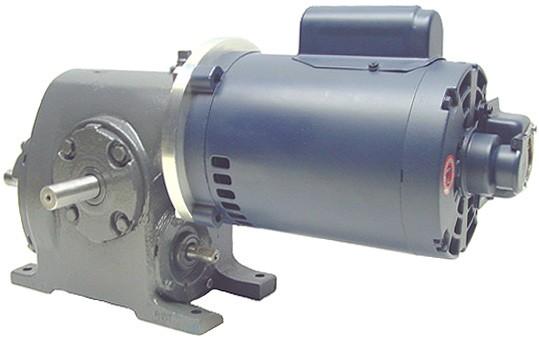
1 New products are developed and released throughout the year. Visit our website regularly pinsetterpartsplus.com GE-Westinghouse-AO Smith Backend Gearbox Conversion Kit Installation Guide New products are developed and released throughout the year. Visit our website regularly pinsetterpartsplus.com


2 Stator Disassembly 1 Using a ¼ nut driver, remove four [] through bolts and carefully remove stator from gearbox. Stator removed and separated from gearbox. To reuse plug, remove two screws securing receptacle to end bell to expose internal wiring. Remove plug leads from terminal board. GE-Westinghouse-Smith - Backend Gearbox Disassembly 1 Drain oil from gearbox. Scribe side cover before removal to ensure proper alignment during re-assembly. Remove shims gently - for reuse in assembly. Remove four [] cap screws from side cover. Gently pry side cover at tabs from housing.


![7 8 Remove six [6] cap screws from offset](/docs-images/80/81677472/images/3-2.jpg "cover.")


3 GE-Westinghouse-Smith - Backend Gearbox Disassembly Continued 5 6 Remove wheel output shaft and cover assembly. Remove Oil Tray. 7 8 Remove six [6] cap screws from offset cover. Remove offset cover, then pull offset output shaft assembly from housing. Gently pry offset cover at tabs from gearbox housing. To remove the Flanged Cover Ring Gear Assembly; use a soft blow hammer gently tap the Flange Cover and carefully 9 10 Protect worm shaft threads, during removal, by installing thick-wall heavy jam nut [/8-] to half thread depth. Remove offset pinion keeper-nut. 11 Using a 5/16 roll pin punch, gently tap the worm shaft through the offset pinion gear. Loosen jam nut as necessary until gear can be safely removed. 1 Remove offset pinion gear and spacer.

![of dust shield from adaptor plate, then remove four [] cap](/docs-images/80/81677472/images/4-2.jpg "screws to remove adapter plate.")


4 GE-Westinghouse-Smith - Backend Gearbox Disassembly Continued 1 1 Turn gearbox housing on-end for easy removal of dust shield from adaptor plate, then remove four [] cap screws to remove adapter plate. Remove rotor worm shaft assembly. Inspection of gearbox parts Before gearbox re-assembly, now is the perfect time to inspect and replace any worn or broken parts. 1. Wheel output shaft assembly - Check bearings for excessive wear and play and gear for excessive wear or damaged teeth. Replace as needed.. Offset output shaft assembly - Check bearings for excessive wear and play and gear for excessive wear or damaged teeth. Replace as needed.. Inboard worm shaft bearing - Check for excessive wear and scoring. Replace as needed.. Rear worm shaft bearing - Check for excessive wear. Replace as needed. 5. Offset pinion gear - Check for excessive wear, cracked or missing teeth. Replace as needed. 6. Replace worn or cracked worm shaft seal. Wheel output shaft assembly Offset output shaft assembly Offset pinion gear Rear worm shaft bearing Inboard worm shaft bearing and seal


![1 Install Conversion Adaptor Plate using four [] cap screws.](/docs-images/80/81677472/images/5-2.jpg "Gently install new keyed Worm Shaft Assembly into housing using care not")


![Seal and install offset output shaft cover using six [6] cap screws.](/docs-images/80/81677472/images/5-7.jpg "5 Install shims aligning mounting bolt holes for ease of install.")
5 GE-Westinghouse-Smith - Backend Gearbox Conversion Assembly For Technical Help - - CALL To keep future gearbox maintenance to a minimum, inspect and replace any damaged worn or cracked seals, shims, and gaskets during re-assembly. 1 Install Conversion Adaptor Plate using four [] cap screws. Gently install new keyed Worm Shaft Assembly into housing using care not to damage threads. Using optional tool PPP-SMTL makes installation easy. Install New Spacer with tapered side towards rear Worm Shaft bearing. Aligned on key, install offset pinion gear onto Worm Shaft. Secure offset pinion gear keeper-nut. Carefully install offset output shaft assembly ensuring proper gear and bearing alignment. Seal and install offset output shaft cover using six [6] cap screws. 5 Install shims aligning mounting bolt holes for ease of install. Install Oil Tray 6 Install wheel output shaft cover with four [] cap screws. Before securing bolts, check output shaft shim-tolerance. Adjust as needed. Fill gearbox with recommended, 1 pint, 150W oil. 5


6 GE-Westinghouse-Smith - Backend Gearbox Conversion For Technical Help - - CALL Installation of a LEESON Backend Motor onto Converted Gearbox Assembly is all that is left. Part No. PPP-70-BE-MTR - back end motor for converted gearboxes Fill gearbox with recommended, 1 pint, 150W oil before installing onto pinspotter PPP-70-BE-GCK-E or PPP-70-BE-GCK-O Contents C-faced adapter plate - Worm shaft and spacer - Mounting hardware 6
GE-Westinghouse-AO Smith
 New products are developed and released throughout the year. Visit our website regularly pinsetterpartsplus.com GE-Westinghouse-AO Smith Combo Gearbox Conversion Kit Installation Guide New products are
DYNATRAC BALL JOINT REBUILD INSTRUCTIONS V5.0
 DYNATRAC PRODUCTS 2007-2018 JEEP JK HEAVY DUTY BALL JOINT JP44-2X3050-C DYNATRAC BALL JOINT REBUILD INSTRUCTIONS V5.0 WARNING: Improper use or installation of this product can cause major failures that
DYNATRAC BALL JOINT REBUILD INSTRUCTIONS V4.0
 DYNATRAC PRODUCTS 2007-2016 4X4 JEEP JK HEAVY DUTY BALL JOINT JP44-2X3050-C DYNATRAC BALL JOINT REBUILD INSTRUCTIONS V4.0 WARNING: Improper use or installation of this product can cause major failures
PROSTEER BALL JOINT REBUILD INSTRUCTIONS V1.0
 DYNATRAC PRODUCTS 2003-2010 4X4 DODGE 2500/3500 HEAVY DUTY BALL JOINT PROSTEER BALL JOINT REBUILD INSTRUCTIONS V1.0 WARNING: Improper use or installation of this product can cause major failures that could
4.4 PUMP MAINTENANCE MODELS: DB, DC, DF, DG, DJ, DL
 4.4 PUMP MAINTENANCE MODELS: DB, DC, DF, DG, DJ, DL 4.4.1 EXPLODED VIEW DRAWING REF. QTY. DB DC DF DG DJ DL DESCRIPTION PART # 1 1 ADAPTOR FRAME 034007 2 12 LOCK WASHER 3/8 x 1/8 S.S. 034004 3 12 HEX HEAD
400 SERIES GRINDER PUMPS 41502, 42202,43302, AND MODELS
 Section: MOYNO 500 PUMPS Page: 1 of 6 Date: March 1, 1998 SERVICE MANUAL MOYNO 500 PUMPS 400 SERIES GRINDER PUMPS 41502, 42202,43302, AND 44402 MODELS DESIGN FEATURES Housing: Cast iron Pump Rotor: Chrome
ITEM NO. PART NO DESCRIPTION QTY.
 PUMP MAINTENANCE ITEM NO. PART NO DESCRIPTION QTY. 1 52002 Center Case 1 2 52052 Back End Plate 1 3 52051 Front End Plate 1 4 55090 Octagonal Nut 1 5 53001 Idler Gear 1 6 53002 Drive Gear 1 7 28062 Bushing
MODELS 49 RA 49 RAZ 49 RAC
 General Safety and Maintenance Manual MODEL grinder featuring a rear exhaust. Model Number Exhaust Direction REAR Throttle Type (L) Lever or (K) Safety Lever Speed 12000 to 14000 R.P.M (13500rpm is standard)
Astro-Physics Inc. 400QMD Lubrication/Maintenance Guide
 Astro-Physics Inc. 400QMD Lubrication/Maintenance Guide The following guidelines should be followed to lubricate the three main parts of the 400QMD mount. The QMD stands for Quartz Micro-Drive controller.
OPERATION AND MAINTENANCE FOR MODEL MRV050A REVERSIBLE
 OPERATION AND MAINTENANCE FOR MODEL MRV050A REVERSIBLE MANUAL AIR MOTOR 04666770 Edition 1 April, 1999 IMPORTANT SAFETY INFORMATION ENCLOSED. READ THIS MANUAL BEFORE OPERATING TOOL. FAILURE TO OBSERVE
5.Use Spray gasket glue or Silicone Sealant on 1214 Valve Plate. When tacky, place on motor block with 1225 timing plate towards front.
 Assembly 2000 1.Press on 1241S Counterweight Guards onto 1215 Motor Block. The end with the hole goes towards the center. Note slot on top of 1215 Block always goes towards the front. Put 1212S Rings on
RTI TECHNOLOGIES, INC.
 RTI TECHNOLOGIES, INC. BRC500 & BRC550 Arbor/Spindle Mechanism Adjustment & Service Technical Instructions The arbor/spindle mechanism of the BRC500/550 is designed to be robust for long life. Occasionally
BRAVO STERN DRIVE 3 C BRAVO ONE
 RAVO STERN DRIVE 3 C 22439 RAVO ONE Table of Contents Page Specifications............................... 3C-1 Torque Specifications..................... 3C-1 Preloads................................ 3C-1
SUPER PRO GUN & SUPER PRO GUN II
 MAGNUM VENUS PRODUCTS Maintenance & Repair Manual Part No. M6707-1-1 Revision 04.14.01 Maintenance & Repair Corporate HQ & Mfg. Phone: (727) 573-2955 Fax: (727) 571-3636 Email: info@magind.com Web: www.magind.com
DO35 MAINTENANCE INSTRUCTIONS
 CUSTOMER INFORMATION SHEET NO. 038 DO35 MAINTENANCE INSTRUCTIONS (DO35 V3 LAUNCHED PRODUCTION JUNE 2017) Table of Contents 1.0 Replacing Spindle Bushes V3... 22 2.0 Replacing Locking Mechanism V3... 6
E30 Limited Slip Clutch Disc Replacement
 E30 Limited Slip Clutch Disc Replacement Disclaimer: The instructions that follow were compiled by amateur mechanics, with input from a few engineers. There is no guarantee that your differential will
PRS Retro Z-Axis Installation
 PRS Retro Z-Axis Installation Page -1- PRS Retro Z-Axis Installation This document is a guide to installing the PRS Retro Z-axis on early ShopBot models. It describes installation for PR models with PK299
SERVICE INSTRUCTIONS Model 9670 Lubricant Pump
 TM TM SERVICE INSTRUCTIONS Model 9670 Lubricant Pump 9670 DESCRIPTION Model 9670 Lubricant Pump is designed to pump light to heavy oils directly from the original container. This design features a 10:1
4.2 - PUMP MAINTENANCE MODELS: AC, AS, WC, WS
 4.2 - PUMP MAINTENANCE MODELS: AC, AS, WC, WS 4.2.1 - EXPLODED VIEW DRAWING REF NO. 1 2 4 QTY 3 1 1.5 5 ¾ HP HP HP HP HP DESCRIPTION PART # 1 CASE 1.25 x 1 NPT 018266 1 CASE 1.25 X 1 NPT 018268 1 CASE
INSTRUCTION MANUAL AND PARTS LIST MODEL 14-10
 VERTICAL BAND SAWS INSTRUCTION MANUAL AND PARTS LIST MODEL 1-10 DAKE/PARMA WHEN ORDERING PARTS GIVE COMPLETE SERIAL NUMBER OF MACHINE GIVE PART NUMBER AND NAME GIVE AMOUNT REQUIRED Unless the above data
Motorized M3 AX7200 Rotary-Style Gasket Cutter Operating Instructions
 Motorized M3 AX7200 Rotary-Style Gasket Cutter Operating Instructions INTRODUCTION Congratulations! You are the owner of the finest rotary-style gasket cutter in the world. Originally developed and patented
REPAIR INSTRUCTIONS. Cat. No Cat. No MILWAUKEE ELECTRIC TOOL CORPORATION. SDS Max Demolition Hammer. SDS Max Rotary Hammer
 Cat. No. 9-0 SDS Max Demolition Hammer Cat. No. -0 SDS Max Rotary Hammer MILWAUKEE ELECTRIC TOOL CORPORATION W. LISBON ROAD BROOKFIELD, WISCONSIN 00-0 8-9-0 d 000 8-9-0 d Special Tools Require Forcing
Inspection. Assembly Install the springs. 1. Discard the 0-rings. 2. Clean all parts in cleaning solvent.
 6010-34 Inspection 3. Install the springs. 1. Discard the 0-rings. 2. Clean all parts in cleaning solvent. 3. If spring test equipment is available, check the tension of each spring according to the specifications
Mechanical Actuators
 Mechanical Actuators Rotating Machine Screw Actuators 2-Ton and Larger Capacity Installation, Operation & Maintenance Instructions Publication Part No. SK-2389-R CAUTION This manual contains important
GENERAL OPERATIONAL PRECAUTIONS PRECAUTIONS ON USING CUT-OFF MACHINE
 GENERAL OPERATIONAL PRECAUTIONS WARNING! When using electric tools, basic safety precautions should always be followed to reduce the risk of fire, electric shock and personal injury, including the following.
CAUTION! This manual contains important information for the correct installation, operation and maintenance of the equipment described herein.
 CAUTION! This manual contains important information for the correct installation, operation and maintenance of the equipment described herein. All persons involved in such installation, operation, and
Series Inline Oscillating Saw
 Parts Manual Ersatzteil Liste 45-8185 12-2065 Series Inline Oscillating Saw IMPORTANT: Read and comply with safety and operating instructions contained in this manual. For additional product information
Removing Right-Side. Components. Right-Side. Components. Click Here to Go Back AT THIS POINT
 Click Here to Go Back NOTE: There is an oil passage beneath the driven gear/drive gear assembly. This passage should be plugged prior to removing the driven gear and drive gear. Failure to do so could
General Four-Way Operation, Maintenance & Service Manual
 General Four-Way Operation, Maintenance & Service Manual SCOPE Included in the following pages you will find assembly drawings, exploded views, parts lists, assembly tips, operational descriptions and
Service Manual. 600 Series Box Frame Steering Shaft and Segment Gear Servicing
 Service Manual 600 Series Box Frame (These procedures are appropriate for box frame tractors produced after November 2002) IMPORTANT: READ SAFETY RULES AND INSTRUCTIONS CAREFULLY This Service Manual is
Installation Instructions
 The IMS ETERNAL FIX PATENT PENDING Installation Instructions EPS recommends professional installation for the Eternal IMS Fix. Please take all precautionary safety measures. We also recommend putting the
Instructions for the installation of Ellison Bronze balanced door models #137 & 138
 1. A packing list will be found in crate No. 1 of each shipment. The parts in the crates should be checked with this list. If there is any discrepancy, notify Ellison Bronze at once. 2. All parts are numbered.
Enginetech Inc Tech Assistance ext. 340 or 237. January 2000 TB 1758
 Enginetech Inc Tech Assistance 800-410-3664 ext. 340 or 237 Mfg: Removal & Replacement Of Rocker Arms & Shaft Assembly On 1993-99 Chrysler 3.2 & 3.5L VIN J, F & G Engines The AERA Technical Committee offers
Click Here to Go Back
 Click Here to Go Back Fig. -94 Fig. -97 CC42D 10. Remove the cap screw securing the gear shift stopper plate pin retainer; then remove the retainer. Fig. -95 CC45D 12. Remove the link arm and account for
MAINTENANCE CLEANING. MECHANICAL SEAL REPLACEMENT Refer to figures 1 and 2. SHIM ADJUSTMENT
 Please read and save this Repair Parts Manual. Read this manual and the General Operating Instructions carefully before attempting to assemble, install, operate or maintain the product described. Protect
MAINTENANCE MANUAL. Hardinge High Speed Super-Precision HLV -H Toolroom and TFB -H Production Lathes
 MAINTENANCE MANUAL HLV machine with optional Acu-Rite III digital readout TP4327 Hardinge High Speed Super-Precision HLV -H Toolroom and TFB -H Production Lathes This maintenance manual applies to machines
WSG 8-115; 8-125; P; WSG ; WSG P; WSG PS; WSG P; WSG 15-70Inox
 Repair instructions Page of 47 Contents. Models described 2. Technical data 3. Notes and requirements 4. Tools required 5. Lubricants and auxiliary substances required 6. Disassembly 7. Assembly 8. Connection
Maintenance Information
 16601023 Edition 2 January 2014 Air Impact Wrench 2705P1 Maintenance Information Save These Instructions Product Safety Information WARNING Failure to observe the following warnings, and to avoid these
DRIVE COMPONENTS REMOVAL. 9. FXCW/C: see Figure Remove bolt (9), sprocket retainer (8), and thrust washer (7). NOTE PRIMARY DRIVE LOCKING TOOL
, sprocket retainer (8), and thrust washer (7). NOTE PRIMARY DRIVE LOCKING TOOL") DRIVE COMPONENTS REMOVAL PART NUMBER HD-7977 TOOL NAME PRIMARY DRIVE LOCKING TOOL S To remove the primary chain, remove compensating sprocket, clutch assembly and primary chain as an assembly:. Remove
DRIVE COMPONENTS REMOVAL PART NUMBER HD-7977 TOOL NAME PRIMARY DRIVE LOCKING TOOL S To remove the primary chain, remove compensating sprocket, clutch assembly and primary chain as an assembly:. Remove
Allow 60 from door face
 Setbacks Allow 60 from door face TOOLS NEEDED Tape Measure Marker or Pencil Masonry Drill Bit 3/8 Hammer Drill Hammer Socket Wrenches and Wrench: 9/16, 1/2, 7/16, 1/4 drive socket wrench and 1/2 socket
HANDWHEEL ASSEMBLY UPGRADE
 HANDWHEEL ASSEMBLY UPGRADE PURPOSE The purpose of the notice is to document the procedures involved in removing old handwheel assembly parts and replacing them with new parts. The new parts allow the handwheel
CS Unitec, Inc. 22 Harbor Avenue, Norwalk, CT Phone: Toll-free:
 CS Unitec, Inc. 22 Harbor Avenue, Norwalk, CT 06850 Phone: 203-853-9522 Toll-free: 800-700-5919 Email: info@csunitec.com CS Unitec, Inc. 22 Harbor Avenue, Norwalk, CT 06850 Phone: 203-853-9522 Toll-free:
PARTS LIST FOR MODEL 7000 SERIES - 17/46
 ITEM PARTS LIST FOR MODEL 7000 SERIES - 17/46 1 Rotor 3 Housing 1 4 End Plate 6 Drive End Cover 1 7 Free End Cover 1 8 Timing Gear Set 1 9 Bearing, Drive End 10 Bearing, Free End 1 Lip Seal, Viton 4 13
Ford Pick Up Rear leaf Spring Kit Installation Instructions
 1948-1956 Ford Pick Up Rear leaf Spring Kit Installation Instructions 1-800-984-6259 www.totalcostinvolved.com Parts 48 inch leaf (2) springs (4) U-bolts 3/8-24 x l 1/4bolts (16) & nuts (2) 1/2-20 x 4
1. TOOLS + MATERIALS REQUIRED
 R INSTALLATION INSTRUCTIONS PRODUCT: BALDUR + ODEN CONFIGURATION: BI-PARTING DOOR MOUNT: TOP MOUNT Product is covered by U.S. patents. For more information visit www.krownlab.com. TOOLS + MATERIALS REQUIRED
LU6X-130 Instructions and Parts List (including LU6X Basic) Operating Instructions
 Operating Instructions") LORTONE LU6X-130 Item # 061-092 LU6X Basic Item # 061-090 LU6X-130 Instructions and Parts List (including LU6X Basic) Operating Instructions Introduction The LU6X is one the most versatile pieces of equipment
LORTONE LU6X-130 Item # 061-092 LU6X Basic Item # 061-090 LU6X-130 Instructions and Parts List (including LU6X Basic) Operating Instructions Introduction The LU6X is one the most versatile pieces of equipment
INSTALLATION OF WELLS SUPER QUICK CHUCK LEFT HAND ON RED WING LATHE
 DENTAL, INC. TECHNICAL BULLETIN Q824-022510 5860 FLYNN CREEK ROAD READ ALL INSTRUCTIONS P.O. BOX 106 BEFORE PROCEEDING COMPTCHE, CALIFORNIA, U.S.A. 95427 SAVE THIS FOR FUTURE REFERENCE www.wellsdental.com
PROPELLER SHAFT PR 3 COMPONENTS
 PR3 COMPONENTS PR4 REMOVAL OF 1. DISCONNECT FRONT (a) Place the matchmarks on the both flanges. (b) Remove the four bolts, washers and nuts. (c) Pull the yoke from the transfer. (d) Insert SST in the transfer
1 of 12 5/24/2015 9:43 AM
 1 of 12 5/24/2015 9:43 AM REAR PROPELLER SHAFT ASSEMBLY Components REMOVAL 1. REMOVE PROPELLER WITH CENTER BEARING SHAFT ASSEMBLY 2 of 12 5/24/2015 9:43 AM a. Place match marks on the propeller shaft flange
HANDHOLE SEAT GRINDER
 1041-1601 HANDHOLE SEAT GRINDER OPERATING INSTRUCTIONS & SERVICE MANUAL Rev: A, 9/17/2007 TO REDUCE THE RISK OF INJURY AND EQUIPMENT DAMAGE USER MUST READ AND UNDERSTAND OPERATOR S MANUAL. Thomas C. Wilson,
RC4WD R2 Disconnect Transmission parts replacement guide
 RC4WD R2 Disconnect Transmission parts replacement guide Version 1.1 Thank you for your purchase. Welcome to the RC4WD family. This transmission is a combination of many specially engineered and manufactured
535A. Main Components. Pipe and Bolt Threading Machine. Printed in U.S.A. Ridge Tool Company/Elyria, Ohio, U.S.A.
 Pipe and Bolt Threading Machine A Main Components 0 Screw, Button Head /" - 0 x /" () Washer, Flat /" ()" Top Cover 0 Base Bottom Cover Screw, Pan Head # - x " () Carriage Assembly 0 Front Support Bar
3000, 4000, 4100, 7500, 7700
 3000, 4000, 4100, 7500, 7700 Drum & Disc Brake Lathes s Identification READ these instructions before placing unit in service. KEEP these and other materials delivered with the unit in a binder near the
PRODUCT: LOKI INSTALLATION INSTRUCTIONS. Product is covered by U.S. patents. For more information visit
 R INSTALLATION INSTRUCTIONS PRODUCT: LOKI CONFIGURATION: SINGLE DOOR MOUNT: GLASS MOUNT Product is covered by U.S. patents. For more information visit www.krownlab.com . TOOLS + MATERIALS REQUIRED TOOLS
Operating Instructions For Lockformer Button Punch Flanger
 Capacity: 20 to 28 Gauge Galvanize Operating Instructions For Lockformer Button Punch Flanger To satisfactorily form the 90º button punch flange on light gauge materials, it was necessary to form the metal
Model 20: Home & Garden Cart
 Model 20: Home & Garden Cart Parts List Step 1: A: Install two ¾ Bolts (C) through the rear trim piece on the Bottom Panel (S) and attach to Lock Nuts. (Lock nuts on bottom side) B: Place left Side Panel
6000, Heavy Duty Drum/Disc Lathe. Parts Identification
 6000, 6002 Heavy Duty Drum/Disc Lathe Parts Identification READ these instructions before placing unit in service. KEEP these and other materials delivered with the unit in a binder near the machine for
MODEL T " SPIRAL CUTTERHEAD INSTALLATION INSTRUCTIONS
 MODEL T27449 8" SPIRAL CUTTERHEAD INSTALLATION INSTRUCTIONS The Model T27449 indexable insert spiral cutterhead is designed to replace the straightknife cutterhead on the Grizzly jointer Model G0490W/G0490XW
PROPELLER SHAFT GROUP CONTENTS GENERAL INFORMATION SPECIAL TOOLS SERVICE SPECIFICATIONS PROPELLER SHAFT...
 25-1 GROUP 25 CONTENTS GENERAL INFORMATION........ 25-2 SERVICE SPECIFICATIONS....... 25-2 LUBRICANTS.................. 25-2 SEALANT...................... 25-2 SPECIAL TOOLS................ 25-2.............
Repair Manual MK40A-MK45A-MK50A MK55A-MK60A-MK65A. Ref Rev.C General Pump is a Member of The Interpump Group
 MK Repair Manual MK40A-MK45A-MK50A MK55A-MK60A-MK65A General Pump is a Member of The Interpump Group 8 INDEX 1. INTRODUCTION..................................................Page 3 2. REPAIR INSTRUCTIONS...........................................Page
PRODUCT: BALDUR + ODEN
 R INSTALLATION INSTRUCTIONS PRODUCT: BALDUR + ODEN CONFIGURATION: SINGLE DOOR MOUNT: GLASS MOUNT Product is covered by U.S. patents. For more information visit www.krownlab.com . TOOLS + MATERIALS REQUIRED
MODEL T27451/T " & 20" SPIRAL CUTTERHEAD INSTRUCTIONS
 MODEL T27451/T27452 15" & 20" SPIRAL CUTTERHEAD INSTRUCTIONS For questions or help with this product contact Tech Support at (570) 546-9663 or techsupport@grizzly.com The T27451 15" & T27452 20" indexable
UNIVERSAL RETROFIT KIT
 UNIVERSAL RETROFIT KIT Midwest Office 444 Lake Cook Road, Suite 22 Deerfield, IL 60015 Phone (847) 940-9305 Fax (847) 940-9315 www.flashcutcnc.com 1998-2012 FlashCut CNC, Inc. Table of Contents THANK YOU...
Legacy Woodworking Machinery a division of Phantom Engineering. The Legacy CNC. Assembly Manual
 Legacy Woodworking Machinery a division of Phantom Engineering The Legacy CNC Assembly Manual New Orientation of the Legacy Step one: Re-orientation of the machine Remove the X-axis screw and supports.
PRODUCT SERVICE MANUAL FOR CIG Mechanical Seal Triple Pumps
 PRODUCT SERVICE MANUAL FOR CIG Mechanical Seal Triple Pumps WARNING The Imo General Installation Operation, Maintenance, and Troubleshooting Manual, (No. SRM00046), as well as all other component manuals
Tapping Screw (W/Flange) 46 Cord Armor 47 Tube (D) 48 Cord. 45 Cord Clip. Tapping Screw (W/Flange) 10 Gear Cover Ass'y. 12 Socket (B) Ass'y
 46 Cord Armor 47 Tube (D) 48 Cord. 45 Cord Clip. Tapping Screw (W/Flange) 10 Gear Cover Ass'y. 12 Socket (B) Ass'y") W8VB The exploded assembly drawing should be used only for authoized service center. W8VB Item No. Part time 1 Magnetic Hex. Socket 2 Sub Stopper 3 O-Ring (S-16) 4 Locator (A) 5 Lock Sleeve (A) 6 O-Ring
W8VB The exploded assembly drawing should be used only for authoized service center. W8VB Item No. Part time 1 Magnetic Hex. Socket 2 Sub Stopper 3 O-Ring (S-16) 4 Locator (A) 5 Lock Sleeve (A) 6 O-Ring
PPM-5710 JK HEAVY DUTY SKID PLATE ASSEMBLY Version 2.0
 SYNERGY MFG. 870 INDUSTRIAL WAY, SAN LUIS OBISPO, CA (805) 242-0397 PPM-5710 JK HEAVY DUTY SKID PLATE ASSEMBLY Version 2.0 GENERAL NOTES: These instructions are also available on our website; www.synergymfg.com.
Midwest RDH Handpiece Repair Procedure
 Midwest RDH Handpiece Repair Procedure The Midwest RDH handpiece is fairly common and is used by hygienists to clean teeth. The most common problems for this handpiece include a bad prophy head or a dirty
H8508 Impact Wrench SERVICE MANUAL. Model (Serial Code FWN) Model (Serial Code FWP)
 Model (Serial Code FWP)") SERVICE MANUAL H8508 Impact Wrench Model 48755 (Serial Code FWN) Model 48760 (Serial Code FWP) Read and understand all of the instructions and safety information in this manual before operating or servicing
SERVICE MANUAL H8508 Impact Wrench Model 48755 (Serial Code FWN) Model 48760 (Serial Code FWP) Read and understand all of the instructions and safety information in this manual before operating or servicing
Pneumatic Drill / / Technical Specification
 CS UNITEC Pneumatic Drill 2 2502 0010 / 2 2502 0030 2 2506 0010 / 2 2506 0030 Technical Specification Model with Lever Throttle Model with Twist Throttle with Selfresetting 2 2502 0010 2 2502 0030 2 2506
INSTRUCTIONS
 ENGINE APPLICATION YEARS/CID: FORD, MERCURY 332, 352, 360, 361, 390, 406, 410, 427, 428 1958-1976 TRANS APPLICATION YEAR/MODEL: GM AUTO PG, TH350, 400, 700R4, CHEVY OR UNI-CASE BOLT PATTERN, IMPORTANT:
PowerLock. Installation Instructions. Attention Dealers: Please give this owners manual to the customer when the product is delivered.
 Serving the Truck & Trailer Industry Since 1944 FOR Attention Dealers: Please give this owners manual to the customer when the product is delivered. Call 800-535-9545 www.aeroindustries.com Indianapolis,
MS25 OPERATION MANUAL
 SAFETY INSTRUCTIONS SPECIFICATIONS OPERATING INSTRUCTIONS MAINTENANCE ADJUSTMENTS REPLACEMENT OF PARTS MS25 DIAGRAM MS25 PARTS LIST MS25 OPERATION MANUAL SAFETY INSTRUCTIONS Please read these instructions
DynaPower Generation II
 DynaPower Generation II Return to DYNAPOWER index Return to MAIN index GENERATION II 2.0 DYNAPOWER MODEL 2.0 VARIABLE PUMP PARTS DRAWING GENERATION II 2.0 DYNAPOWER MODEL 2.0 VARIABLE PUMP PARTS DRAWING
How To: Automatic Transmission Indicator Pin Replacement PRNDL. Introduction
 How To: Automatic Transmission Indicator Pin Replacement PRNDL Introduction This How To explains how I would remove the indicator pin from a second gen VCV. Improvements or clarifications to this technique
RP-VE416FS/FSD VE416FS and VE416FSD Roll Grooving Tools
 PARTS ORDERING INFORMATION When ordering parts, the following information is necessary for Victaulic to process the order promptly: 1. Tool Model Number VE416FS or VE416FSD 2. Tool Serial Number The Serial
General Safety and Maintenance Manual
 General Safety and Maintenance Manual 3 H.P HORIZONTAL GRINDERS CAPACITY -6 Inch (150 mm) or 8 Inch (200 mm) Type 1 Wheels -Any Type 16, 17, 17R, 18 or 18R Cone Wheels w/ 5/8-11 Mounting 3 H.P HORIZONTAL
Assembly & Installation Instructions FOR VEHICLE MOUNT KIT USING VEHICLE CENTER MEMBER
 Assembly & Installation Instructions FOR VEHICLE MOUNT KIT 991002 USING VEHICLE CENTER MEMBER 9910092 TO FIT 99 - LATER Chevrolet 2500 Silverado 4x4 and 3500 Pickup 4x4 99 - LATER GM 2500 Sierra 4x4 and
COMBINATION STRAPPING TOOL
 AM COMBINATION STRAPPING TOOL READ THESE INSTRUCTIONS CAREFULLY. FAILURE TO FOLLOW THESE INSTRUCTIONS CAN RESULT IN SEVERE PERSONAL INJURY. GENERAL SAFETY CONSIDERATIONS 1. STRAP BREAKAGE HAZARD. Improper
Maintenance & Parts list for:
 Maintenance & Parts list for: Industrial gun GB 2 Juni 2017 This Maintenance & Parts list for industrial gun is prepared by : Winchester Europe Service V. Parbst & Søn as a comprehensive maintenance guide
A-PDF Split DEMO : Purchase from to remove the watermark SHAFT DRIVE
 SHAFT DRIVE 4-1 A-PDF Split DEMO : Purchase from www.a-pdf.com to remove the watermark SHAFT DRIVE CONTENTS SECONDARY BEVEL GEARS... 4-2 CONSTRUCTION... 4-2 REMOVAL... 4-4 DISASSEMBLY... 4-4 INSPECTION...
Big Block Installation Manual For Systems without A/C
 Big Block Installation Manual For Systems without A/C Billet Specialties, Inc. 500 Shawmut Ave. La Grange, IL 60526 Tech Line (708) 588-0505 Fax (708) 588-7181 Hardware List For Chevrolet Big Block Tru
Required Tools: Procedure:
 Depending on the materials you process through your chipper, their moisture content, the climate you live in, and many other factors you may have difficulty removing the rotor from the engine shaft. The
General Safety and Maintenance Manual 3 H.P HORIZONTAL GRINDERS. and Thread RPM T1-5/8-11 X 1.9. Lever. Lever. Handle
 HENRY TOOLS Industrial Airtools at Work General Safety and Maintenance Manual 3 H.P HORIZONTAL GRINDERS 3 H.P HORIZONTAL GRINDERS Capacity: -6 Inch (150 mm) or 8 Inch (200 mm) Type 1 Wheels -Any Type 16,
HR24TS Rotary Rake. Serial Numbers less than Illustrated Parts Breakdown. Curtain & Guards, Front
 HRTS Rotary Rake Serial Numbers less than 00 Illustrated Parts Breakdown Page Page Page Page Page Page Page Page Page Page Page Page Tongue Front Frame Front Axle Curtain & Guards, Front Front Pivot Bridge
`48-`56 Ford Pickup Rear leaf Spring Kit Installation Instructions Tech Line:
 `48-`56 Ford Pickup Rear leaf Spring Kit Installation Instructions Tech Line: 1-855-693-1259 www.totalcostinvolved.com CHECK ALL PARTS INCLUDED IN THIS KIT TO THE PARTS LIST BEFORE INSTALLING THE KIT.
AT ADAPTER INSTALLATION INSTRUCTIONS
 IMPORTANT: THIS IS A HIGH PERFORMANCE PART AND IMPROPER INSTALLATION COULD RESULT IN INJURY OR DEATH! NEVER WORK UNDER AN AUTOMOBILE THAT IS NOT PROPERLY SUPPORTED AND BLOCKED FROM ROLLING. NO CREDIT OR
w w w. h d o n l i n e s h o p. d e TIMKEN BEARING CONVERSION TOOL GENERAL INSTALLATION -J04672 REV Kit Number Models
 -J067 REV. 008-07- GENERAL Kit Number 8-08 Models TIMKEN BEARING CONVERSION TOOL For model fitment information, see the P&A Retail Catalog or the Parts and Accessories section of www.harley-davidson.com
OPERATIONS MANUAL. Port-O-Slitter
 Tapco Products Company The World Leader in Specialty Tools for the Professional Port-O-Slitter OPERATIONS MANUAL General instructions, set up, accessories and guide to using your portable precision slitting,
Power Output. Spindle. 7.7 Inches (196 cm) 11.0 Lbs. (5.0 Kg)
 11.0 Lbs. (5.0 Kg)") HENRY TOOLS Industrial Airtools at Work General Safety and Maintenance Manual SUPER HEAVY DUTY VERTICAL GRINDERS 4 Horsepower Vertical Grinders 4 HORSEPOWER Model Number Throttle Type Power Output Weight
HENRY TOOLS Industrial Airtools at Work General Safety and Maintenance Manual SUPER HEAVY DUTY VERTICAL GRINDERS 4 Horsepower Vertical Grinders 4 HORSEPOWER Model Number Throttle Type Power Output Weight
Fig Remove chain cover plate bolts. Fig Remove hammer member. Fig Loosen set screws at base of 12-tooth sprocket.
 Fig. 17.2. Remove chain cover plate bolts. Fig. 17.1. Remove hammer member. Fig. 17.3. Remove chain cover plate. Fig. 17.4. Loosen set screws at base of 12-tooth sprocket. Page 61 Fig. 17.5. Remove socket
ST1014 PARTS ST1014 Headstock Breakdown
 ST1014 PARTS ST1014 Headstock Breakdown 112 114 23 104 105 108 102 106 20 19 21 22 101 100 103 111 38 14 15 37 46 44 47 45 107 93 39 41 40 67 110 109 74 75 76 11 12 13 9 8 6 10 31-2 31-3 3 2 7 26 24 31-1
MODEL H " BYRD SHELIX CUTTERHEAD INSTRUCTIONS
 MODEL H9291 12" BYRD SHELIX CUTTERHEAD INSTRUCTIONS The Model H9291 12" Byrd Shelix cutterhead is designed to replace the straight-knife cutterhead on the Grizzly jointer Model G0609. The total procedure
MECHANICAL MAINTENANCE SKILLS
 MECHANICAL MAINTENANCE SKILLS COURSE 700: 5 DAYS: Max 4 Candidates This course provides personnel with the necessary skills to perform mechanical maintenance, including the removal and replacement of equipment
SERIES I MILLING MACHINES
 INSTALLATION, OPERATION, MAINTENANCE, AND PARTS LIST SERIES I MILLING MACHINES TP5260 Revised: August 29, 2005 Manual No. M-450 Litho in U.S.A. Part No. M -0009500-0450 June, 2003 MAINTENANCE PROCEDURES
30DC Speed Lathe Manual
 30DC Speed Lathe Manual The Crozier Model 30DC Speed Lathe is our most popular model. It has many standard features not found on any other machine in its class or price range. Standard Features 3/4 HP
OPERATION & MAINTENANCE MANUAL
 OPERATION & MAINTENANCE MANUAL AUTOMATIC PECAN CRACKER Food Processing Equipment and Machinery Specializing in the Pecan Industry Mailing: PO Box 817, Mansfield, Louisiana 71052 Located: 280 Independence
Disassembly. & Reassembly. S Series. Twin Screw Pumps. MAAG E-02EMEA TO REPLACE MAAG E-01
 Disassembly & Reassembly S Series Twin Screw Pumps W h e r e I n n o v a t i o n F l o w s www.maag.com MAAG-14020-E-02EMEA TO REPLACE MAAG-14020-E-01 TABLE OF CONTENTS SECTION 1 INTRODUCTION... 1 SAFETY
INSTRUCTIONS
 IMPORTANT: THIS IS A HIGH PERFORMANCE PART AND IMPROPER INSTALLATION COULD RESULT IN INJURY OR DEATH! NEVER WORK UNDER AN AUTOMOBILE THAT IS NOT PROPERLY SUPPORTED AND BLOCKED FROM ROLLING. NO CREDIT OR
Inventory (Figure 2)
") MODEL T10130/T10126 6" & 8" SPIRAL CUTTERHEAD INSTRUCTIONS The Model T10126/T10130 indexable insert spiral cutterheads are designed to replace straightknife cutterheads from the Grizzly jointer Models
MODEL T10130/T10126 6" & 8" SPIRAL CUTTERHEAD INSTRUCTIONS The Model T10126/T10130 indexable insert spiral cutterheads are designed to replace straightknife cutterheads from the Grizzly jointer Models