Series Inline Oscillating Saw
|
|
|
- Dustin Powers
- 5 years ago
- Views:
Transcription

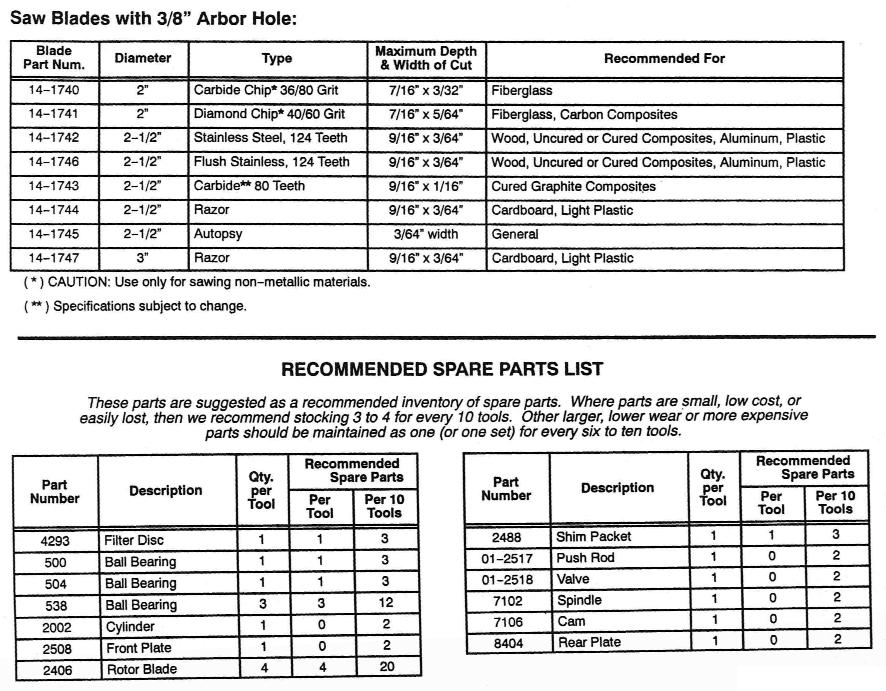
1 Parts Manual Ersatzteil Liste Series Inline Oscillating Saw IMPORTANT: Read and comply with safety and operating instructions contained in this manual. For additional product information visit our website at CooperTools P.O. BOX 1410 Lexington, South Carolina
2 Page 2
3 Page 3
4 DISASSEMBLY INSTRUCTIONS To Disassemble Complete Saw: 1.) Place the special 12-point socket wrench, part # , horizontally in a vise and insert the tool s vertically into the wrench. unthread Saw Head Assembly. Unthread Housing Adapter, part #7101, from Spindle Housing, part #7100 Note: Left hand threads. To Disassemble Saw Head Assembly: 2.) Unthread Lock Ring, part #7105, from Spindle Housing, part #7100. Unthread Spindle Adapter, part #7107, from Spindle, part #7102. Remove spindle from Spindle Housing, part #7100. Remove Both Ball Bearings, part #538, and Spacers, part # s 7103 & 7104, from front of Spindle Housing. To Remove & Disassemble Motor: 3.) Once the saw head assembly has been removed, pull motor from housing. Hold motor in one hand and tap the rear of Rotor, part #7005, with a brass drive punch until Rear Plate, part #8404 and Ball Bearing, part #538, are free from rotor. Remove Cylinder, part #2002, and four Rotor Blades, part #2406. Cam, part #7106, may be removed by holding the rotor in soft vise jaws and unthreading the cam. The Front Plate, part #2508, and Ball Bearing, part #500, can now be pressed off. Note: Do not lose Spacer, part #2017, from the rotor. Press Ball Bearing, part #504, off cam. ASSEMBLY INSTRUCTIONS All parts should be thoroughly cleaned and inspected before assembly. Ball Bearing are normally replaced in most repairs. To Assemble Motor: 4.) Make sure all parts are cleaned and oiled. Press Pins, part #1041, if necessary, into the motor end plates. To Correct for bearing tolerances, it is necessary to use shims to maintain correct clearances between the ends of the rotor and the bearing plates. Shim Packet, part #2488, contains a.001 shim and two.002 shims. Insert a.002 Shim in the Front Bearing Plate s pocket and install #500 Ball Bearing into the Front Plate.Also Install #538 Ball Bearing into the Rear Bearing Plate, part #2017, onto the threaded end of the Rotor. Support the tool on the rear end and assemble the front plate assembly onto the rotor by pressing on the bearings inner race. Press ball Bearing, part #504, onto the front of cam, part #7106, and then thread Cam, part #7106, onto rotor tightly by holding rotor in soft vise jaws. Service Instructions 5.) Hold rotor in left hand and front bearing plate in the other hand. Apply an outward (pulling) pressure and observe the spacing between the end of the rotor and the bearing plate. This must be from flush, not rubbing, to.002 maximum. If the rotor rubs the bearing plate, reduce the spacing between the bearing and bearing plate by removing the.002 shim entirely, or by substituting the.001 shim for the.002 shim. However, if there was more than.002 between the bearing and bearing plate, add.001 shim between the bearing and bearing plate. Install Cylinder, part #2002. Note: Be sure cylinder is not on backwards, air inlet in cylinder must line up with air inlet in Rear Plate, part #8404, when Pin, part #1041, is engaged in mating slot of cylinder. 6.) Insert all four Rotor Blades, part #2406, in rotor. Support the assembly on the face of the Cam, part #7106. Press on the Rear Plate, part #8404, by pressing on the inner race of Ball Bearing, part #538, just enough to bring the bearing plate up against the cylinder. There should be only a slight drag between the bearing plate and the cylinder when these rae moved in the fingers. To Assemble Saw Head Assembly: 7.) make certain all parts are properly cleaned. Insert two Ball bearings, part #538, with Spacers, part # s 7103 & 7104, between bearings, into small end of Spindle Housing, part #7100. Insert Spindle, part #7102, in opposite end of Spindle Housing, part #7100, through both bearings. Thread on Adapter, part #7107, and lock in place. Thread in Lock Ring, part #7105, and Lock in place. To Assemble Saw Head To Motor Assemble: 8.) Thread Spindle Housing, part #7100, onto Housing Adapter, part #7101. Note: Left hand threads. Do not tighten at this time. Now, thread Housing Adapter, part #7101, onto Motor housing, part # , making sure that Cam, part #7106, and Spindle, part #7102, are properly engaged. 9.) Orient Output Spindle Housing, part #7100, to desired position and tighten Housing Adapter, part #7101. Page 4
5 ALWAYS COMPLY WITH: 1. General industry Safety & Health Regulations, Part 1910, OSHA 2206, available from: Sup t of Documents; Government Printing Office; Washington, DC Safety Code of Portable Air Tools, ANSI B186.1 available from: American National Standards Institute, Inc.; 1430 Broadway; New York, NY State and Local regulations. Portions of the above codes and regulations are listed below for quick reference. THE FOLLOWING EXCERPTS ARE NOT INTENDED TO BE ALL INCLUSIVE: STUDY AND COMPLY WITH ALL REGULATIONS! Safety First! 1. TOOL INTENT: Tools shall be used only for purposes intended in their design (refer to product catalog). 2. AIR SUPPLY: Test and operate tools at 90 PSIG maximum unless tool is marked otherwise. Use recommended airline filters-regulators-lubricators. 3. UNUSUAL SOUND or VIBRATION: If tool vibrates or produces an unusual sound, repair immediately for correction. 4. OPERATOR PROTECTIVE EQUIPMENT: Wear goggles or face shield at all times tool is in operation. Other protective clothing shall be worn, if necessary. SEE REGULATIONS. 5. SAFETY MAINTENANCE PROGRAM: Employ a safety program to provide inspection and maintenance of all phases of tool operation and air supply equipment in accordance with Safety Code for Portable Air Tools. CAUTION: Disconnect the air supply hose before servicing the tool. INSTALLATION: For best performance, a working air pressure of 90 pounds per square inch is recommended. Pipings, fittings, and hose should be adequate to maintain 90 psig while the tool in in operation. An air line filter and lubricator, such as CooperTools #F02-M Filter (1/4 NPT) and #L02-EP Lubricator (1/4 NPT) should be used (refer to product catalog). Hose should be blown out before attaching to tool. LUBRICATION: The gears in angle head style tools must be lubricated every 8 hours of operation with high quality gear grease. CooperTools grease # is recommended. A Grease Gun, # , is furnished with each geared tool. Insert the nozzle into the flush type lube fitting, located on the side or top of the angle head, and pump four or five times. The motor must be lubricated and moisture free. Use a high grade SAE #5 spindle oil, such as CooperTools Lubricating oil # (one quart). Two or three drops per minute should be sufficient lubrication. NOTE: Turbine motor type tools (10-90 & 10-95) must NOT be oiled. LOSS OF POWER: It is seldom necessary to disassemble this tool for loss of power. A loss of power may not be related to the tool. First, check the air line regulator. Also, check the air line pressure; it should be 90 psig at or near the tool while the tool is running. Check the size of hose and fittings to be certain they are not causing air restrictions. Make certain they are not plugged with dirt, rust, or scale. SERVICE INSTRUCTIONS: The parts of this tool are small and require careful handling. We recommend the tool be returned to the factory for repair. However, if the tool is to be repaired in the field, carefully follow instructions. Do not squeeze the tool or parts in a vise except as specified. Care must be used during assembly and disassembly. When pressing bearings onto a shaft, press only on the inner race. When pressing bearings into a bore, press on the outer race only. NOTE: Ball bearings are the shielded type. They are lubricated for life by the bearing manufacturer and should not be washed out with solvents to clean. WARNING! CHECK SPEED OF TOOL WITHOUT WHEEL BEFORE IT IS RELEASED FOR USE. The SPEED TOLERANCE is rated speed minus 10%. The tool must NOT have a free speed higher than the RPM stamped on the housing. Use an accurate tachometer to check the tool speed, with 90 psig air pressure at the tool with the tool running. Page 5
Power Output. Spindle. 7.7 Inches (196 cm) 11.0 Lbs. (5.0 Kg)
 11.0 Lbs. (5.0 Kg)") HENRY TOOLS Industrial Airtools at Work General Safety and Maintenance Manual SUPER HEAVY DUTY VERTICAL GRINDERS 4 Horsepower Vertical Grinders 4 HORSEPOWER Model Number Throttle Type Power Output Weight
HENRY TOOLS Industrial Airtools at Work General Safety and Maintenance Manual SUPER HEAVY DUTY VERTICAL GRINDERS 4 Horsepower Vertical Grinders 4 HORSEPOWER Model Number Throttle Type Power Output Weight
MODELS 49 RA 49 RAZ 49 RAC
 General Safety and Maintenance Manual MODEL grinder featuring a rear exhaust. Model Number Exhaust Direction REAR Throttle Type (L) Lever or (K) Safety Lever Speed 12000 to 14000 R.P.M (13500rpm is standard)
OPERATION AND MAINTENANCE FOR MODEL MRV050A REVERSIBLE
 OPERATION AND MAINTENANCE FOR MODEL MRV050A REVERSIBLE MANUAL AIR MOTOR 04666770 Edition 1 April, 1999 IMPORTANT SAFETY INFORMATION ENCLOSED. READ THIS MANUAL BEFORE OPERATING TOOL. FAILURE TO OBSERVE
SHEREX FASTENING SOLUTIONS PNEUMATIC SPIN-SPIN INLINE STYLE RIVET NUT INSTALLATION TOOL SSG-902 MANUAL
 SHEREX FASTENING SOLUTIONS PNEUMATIC SPIN-SPIN INLINE STYLE RIVET NUT INSTALLATION TOOL SSG-902 MANUAL SSG-902 Specifications R.P.M. - 1500 *Air Pressure - 60-90 psi (oiled) Weight - 2 lbs. (0.9 kg) Air
General Safety and Maintenance Manual
 General Safety and Maintenance Manual 4 H.P HORIZONTAL GRINDERS CAPACITY -6 Inch (150 mm) or 8 Inch (200 mm) Type 1 Wheels -Any Type 16, 17, 17R, 18 or 18R Cone Wheels w/ 5/8-11 Mounting 65H Series 4 H.P
General Safety and Maintenance Manual 3 H.P HORIZONTAL GRINDERS. and Thread RPM T1-5/8-11 X 1.9. Lever. Lever. Handle
 HENRY TOOLS Industrial Airtools at Work General Safety and Maintenance Manual 3 H.P HORIZONTAL GRINDERS 3 H.P HORIZONTAL GRINDERS Capacity: -6 Inch (150 mm) or 8 Inch (200 mm) Type 1 Wheels -Any Type 16,
SHEREX FASTENING SOLUTIONS PNEUMATIC SPIN-SPIN RIGHT ANGLE INLINE STYLE RIVET NUT INSTALLATION TOOL SSG-913 MANUAL
 SHEREX FASTENING SOLUTIONS PNEUMATIC SPIN-SPIN RIGHT ANGLE INLINE STYLE RIVET NUT INSTALLATION TOOL SSG-913 MANUAL SSG-913 Specifications R.P.M. - 400 *Air Pressure - 80-110 psi (oiled) Weight - 2.3 lbs.
Maintenance Information
 16601023 Edition 2 January 2014 Air Impact Wrench 2705P1 Maintenance Information Save These Instructions Product Safety Information WARNING Failure to observe the following warnings, and to avoid these
General Safety and Maintenance Manual
 General Safety and Maintenance Manual 3 H.P HORIZONTAL GRINDERS CAPACITY -6 Inch (150 mm) or 8 Inch (200 mm) Type 1 Wheels -Any Type 16, 17, 17R, 18 or 18R Cone Wheels w/ 5/8-11 Mounting 3 H.P HORIZONTAL
HANDHOLE SEAT GRINDER
 1041-1601 HANDHOLE SEAT GRINDER OPERATING INSTRUCTIONS & SERVICE MANUAL Rev: A, 9/17/2007 TO REDUCE THE RISK OF INJURY AND EQUIPMENT DAMAGE USER MUST READ AND UNDERSTAND OPERATOR S MANUAL. Thomas C. Wilson,
4.4 PUMP MAINTENANCE MODELS: DB, DC, DF, DG, DJ, DL
 4.4 PUMP MAINTENANCE MODELS: DB, DC, DF, DG, DJ, DL 4.4.1 EXPLODED VIEW DRAWING REF. QTY. DB DC DF DG DJ DL DESCRIPTION PART # 1 1 ADAPTOR FRAME 034007 2 12 LOCK WASHER 3/8 x 1/8 S.S. 034004 3 12 HEX HEAD
To remove sanding pad, turn counterclockwise.
 Disassembly Instructions - Dynorbital EXTREME Models: All Important: Disconnect sander from the air supply. Notice: Use these instructions along with the tool manual. To avoid damage, use the special repair
400 SERIES GRINDER PUMPS 41502, 42202,43302, AND MODELS
 Section: MOYNO 500 PUMPS Page: 1 of 6 Date: March 1, 1998 SERVICE MANUAL MOYNO 500 PUMPS 400 SERIES GRINDER PUMPS 41502, 42202,43302, AND 44402 MODELS DESIGN FEATURES Housing: Cast iron Pump Rotor: Chrome
H6400, H6400C1 & VSD6400 REVERSIBLE DRILLS
 SERVICE MANUAL H6400, H6400C1 & VSD6400 REVERSIBLE DRILLS Read and understand all of the instructions and safety information in this manual before operating or servicing this tool. 999 1801.3 REV 4 2001
Engineering Data Single Reduction Parts List Item # Description Basic Single Reduction Unit 1. Gear Housing 2. Pipe Plug 3. Vent Plug 4. Splash Guard
 Engineering Data Single Reduction Parts List Item # Description Basic Single Reduction Unit 1. Gear Housing 2. Pipe Plug 3. Vent Plug 4. Splash Guard 5. Input Cover 6. O-Ring 7. Hex Head Cap Screw 8. Input
A socket contact support (supplied separately) must be installed onto the locator assembly.
 must be installed onto the locator assembly.") Figure 1 PRO CRIMPER III Hand Tool Assembly 1976444 1 consists of PRO CRIMPER III Hand Tool Frame 354940 1 and Die Assembly 1976444 2. The tool assembly is used to crimp the contacts listed in Figure 1.
Figure 1 PRO CRIMPER III Hand Tool Assembly 1976444 1 consists of PRO CRIMPER III Hand Tool Frame 354940 1 and Die Assembly 1976444 2. The tool assembly is used to crimp the contacts listed in Figure 1.
INSTRUCTION BOOK AND PARTS LIST
 Rag Cutter MODEL WE WARNING This machine is equipped with a very sharp knife. Keep hands, arms, and hair away from the knife area at all times. Misuse of this machine or failure to follow all safety instructions
1. Turn off or disconnect power to unit (machine). 2. Push IN the release bar on the quick change base plate. Locking latch will pivot downward.
. 2. Push IN the release bar on the quick change base plate. Locking latch will pivot downward.") Figure 1 Miniature Quick Change Applicators, of the end feed type, are designed to crimp end feed strip terminals to prestripped wires. Each applicator is set up to accept the strip form of certain specific
Figure 1 Miniature Quick Change Applicators, of the end feed type, are designed to crimp end feed strip terminals to prestripped wires. Each applicator is set up to accept the strip form of certain specific
Rev B C-RING TOOL VA0375 ½ in. OPERATING MANUAL
 Rev B 4-30-0 C-RING TOOL VA0375 ½ in. OPERATING MANUAL Operational Instructions for Vertex C-Ring Tool VA0375 Vertex Fasteners is committed to providing our customers with world-class customer service
Fig Remove chain cover plate bolts. Fig Remove hammer member. Fig Loosen set screws at base of 12-tooth sprocket.
 Fig. 17.2. Remove chain cover plate bolts. Fig. 17.1. Remove hammer member. Fig. 17.3. Remove chain cover plate. Fig. 17.4. Loosen set screws at base of 12-tooth sprocket. Page 61 Fig. 17.5. Remove socket
General Four-Way Operation, Maintenance & Service Manual
 General Four-Way Operation, Maintenance & Service Manual SCOPE Included in the following pages you will find assembly drawings, exploded views, parts lists, assembly tips, operational descriptions and
PEDESTAL OVERHAUL. Some of the tools for a pedestal overhaul. Pedestal work stand
 INTRODUCTION A properly greased labyrinth seal will help prevent dust and water damage to the pedestal bearing oil supply and shaft seal area. Properly greased and oiled pedestals rarely require an overhaul.
Tail Rotor Spindle Assembly Repair Procedure
 Tail Rotor Spindle Assembly Repair Procedure Disassembly 1. Remove tail rotor assembly and blade assemblies in accordance with: a. TH28/480 Series MM-9-107 b. F-28F/280FX Series MM-10-2 2. Clamp spindle
OPERATING INSTRUCTIONS
 OPERATING INSTRUCTIONS ROTARY VANE POSITIVE DISPLACEMENT DRY-AIR PUMPS VAPOR-OIL PUMPS MADE IN AMERICA SINCE 1939 CONGRATULATIONS! You have purchased one of the most dependable and thoroughly proven Rotary
H8508 Impact Wrench SERVICE MANUAL. Model (Serial Code FWN) Model (Serial Code FWP)
 Model (Serial Code FWP)") SERVICE MANUAL H8508 Impact Wrench Model 48755 (Serial Code FWN) Model 48760 (Serial Code FWP) Read and understand all of the instructions and safety information in this manual before operating or servicing
SERVICE MANUAL H8508 Impact Wrench Model 48755 (Serial Code FWN) Model 48760 (Serial Code FWP) Read and understand all of the instructions and safety information in this manual before operating or servicing
Model: SCD430 SCD640. Installation & Operation Guide P/N SCD640-95
 Model: SCD430 SCD640 Installation & Operation Guide P/N SCD640-95 Model SCD430 and SCD640 Kurt has two Self-Centering vises, a four-inch jaw width (SCD430) and a six-inch jaw width (SCD640). Jaw opening
DODGE Grease Lubricated SPLIT-SPHER Roller Bearings and Pillow Blocks
 Mounting Instructions For DODGE Grease Lubricated SPLIT-SPHER Roller Bearings and Pillow Blocks WARNING: Because of the possible danger to person(s) or property from accidents which may result from the
H4670/42192 Submersible Trash Pump
 SERVICE MANUAL H4670/42192 Submersible Trash Pump Serial Code GLW Read and understand all of the instructions and safety information in this manual before operating or servicing this tool. 99916070 REV
OPERATIONS AND MAINTENANCE MANUAL DOUBLE KNIFE EDGE RCM DOOR
 OPERATIONS AND MAINTENANCE MANUAL DOUBLE KNIFE EDGE RCM DOOR NOTICE: INFORMATION IN THIS MANUAL IS THE PROPERTY OF LINDGREN RF ENCLOSURES AND MAY BE COVERED BY PENDING PATENTS. THIS INFORTMATION IS PROVIDED
PNEUMATIC C-RING TOOLS SC73462 SAFETY INSTRUCTIONS. WARNINGS Always read tool manual before operating.
 PNEUMATIC C-RING TOOLS SC73462 SAFETY INSTRUCTIONS WARNINGS Always read tool manual before operating. Always wear safety glasses while operating or while in the vicinity of a tool in operation. For testing,
IF YOU DO NOT KNOW WHAT YOU ARE DOING, DO NOT DO IT!
 TWIN CAM Alpha & Beta Case Boring Tool The JIMS Twin Cam Case Boring Tool takes all the guess work out of boring Twin Cam engine cases to accept JIMS 4" bore cylinders, 100 big bore kit, and 113" and 116"
MUELLER GAS. DH-5/EH-5 Drilling. Reliable Connections. DH-5 Drilling Machine General Information 2. EH-5 Drilling Machine General Information 3
 operating Instructions manual MUELLER GAS TAble of contents PAGE DH-5 Drilling Machine General Information 2 DH-5/EH-5 Drilling EH-5 Drilling Machine General Information 3 Operating Instructions 4-5 DH-5
30DC Speed Lathe Manual
 30DC Speed Lathe Manual The Crozier Model 30DC Speed Lathe is our most popular model. It has many standard features not found on any other machine in its class or price range. Standard Features 3/4 HP
SECTION 7 - SUSPENSION
 For Arctic Cat Discount Parts Call 606-678-9623 or 606-561-4983 SECTION 7 - SUSPENSION TABLE OF CONTENTS Section Front and Rear Suspension Assembly Schematics... 7-2 Shock Absorbers... 7-4 Swing Arms (ACT
Page 1. SureMotion Quick-Start Guide: LARSACC_QS 1st Edition - Revision A 03/15/16. Standard Steel Bolt/Screw Torque Specifications
 R K C T I Repair Kit Product Compatibility Repair Kit # Linear Actuator Assembly # LARSACC-013 LARSACC-014 LARSD2-08T12BP2C (12-in travel) LARSD2-08T24BP2C (24-in travel) C P I R K 1 ea Ball Screw with
GE-Westinghouse-AO Smith Backend Gearbox Conversion Kit Installation Guide
 New products are developed and released throughout the year. Visit our website regularly pinsetterpartsplus.com GE-Westinghouse-AO Smith Backend Gearbox Conversion Kit Installation Guide New products are
RTI TECHNOLOGIES, INC.
 RTI TECHNOLOGIES, INC. BRC500 & BRC550 Arbor/Spindle Mechanism Adjustment & Service Technical Instructions The arbor/spindle mechanism of the BRC500/550 is designed to be robust for long life. Occasionally
Core EZ. Operating Manual. Toll Free B East Broadway Avenue Tampa, FL 33619
 Operating Manual 3702 West Central Avenue Santa Ana, CA 92704 Toll Free 1-866-987-7297 11 High Street Suffield, CT 06078 www.ussaws.com 8004B East Broadway Avenue Tampa, FL 33619 Introduction This manual
Disassembly Instructions - 1 hp. Planetary Reduction Gears
 Disassembly Instructions - 1 hp. Planetary Reduction Gears Important: Use these instructions along with the tool parts page or manual. Notice: To avoid damage to the motor housing, use the Special Repair
SUPER PRO GUN & SUPER PRO GUN II
 MAGNUM VENUS PRODUCTS Maintenance & Repair Manual Part No. M6707-1-1 Revision 04.14.01 Maintenance & Repair Corporate HQ & Mfg. Phone: (727) 573-2955 Fax: (727) 571-3636 Email: info@magind.com Web: www.magind.com
3/8 Butterfly Air Impact Wrench
 3/8 Butterfly Air Impact Wrench 37730 ASSEMBLY AND OPERATING INSTRUCTIONS 3491 Mission Oaks Blvd., Camarillo, CA 93011 Visit our Web site at http://www.harborfreight.com Copyright 2004 by Harbor Freight
Throttle Type. per Minute Inches (412 mm) (L) Lever
 (L) Lever") HENRY TOOLS Industrial Airtools at Work General Safety and Maintenance Manual Model Number Bore and Stroke 1.0 Inch x 2.0 Inch (25 mm x 51 mm) Throttle Type (L) Lever Blows Length per Minute 2500 16.2
HENRY TOOLS Industrial Airtools at Work General Safety and Maintenance Manual Model Number Bore and Stroke 1.0 Inch x 2.0 Inch (25 mm x 51 mm) Throttle Type (L) Lever Blows Length per Minute 2500 16.2
MS25 OPERATION MANUAL
 SAFETY INSTRUCTIONS SPECIFICATIONS OPERATING INSTRUCTIONS MAINTENANCE ADJUSTMENTS REPLACEMENT OF PARTS MS25 DIAGRAM MS25 PARTS LIST MS25 OPERATION MANUAL SAFETY INSTRUCTIONS Please read these instructions
SERVICE INSTRUCTIONS Model 9670 Lubricant Pump
 TM TM SERVICE INSTRUCTIONS Model 9670 Lubricant Pump 9670 DESCRIPTION Model 9670 Lubricant Pump is designed to pump light to heavy oils directly from the original container. This design features a 10:1
SAFETY INSTRUCTIONS. WARNINGS Always read tool manual before operating.
 SAFETY INSTRUCTIONS WARNINGS Always read tool manual before operating. Always wear safety glasses while operating or while in the vicinity of a tool in operation. For testing, always cycle tool away from
SAVE THIS FOR FUTURE REFERENCE THIS PRODUCT IS FOR PROFESSIONAL LABORATORY USE ONLY USER'S MANUAL
 DENTAL, INC. TECHNICAL BULLETIN G801-022510 5860 FLYNN CREEK ROAD READ ALL INSTRUCTIONS P.O. BOX 106 BEFORE PROCEEDING COMPTCHE, CALIFORNIA, U.S.A. 95427-0106 SAVE THIS FOR FUTURE REFERENCE www.wellsdental.com
MODEL SK61732 COMPRESSOR SERVICE KIT
 MODEL SK61732 COMPRESSOR SERVICE KIT For use on 607 and 617 Model Compressors with.32 Stroke WARNING: Unplug the compressor before beginning disassembly. CAUTION: Improper assembly or use of damaged parts
MUELLER E-5TM. and D-5TM. Drilling Machines. Reliable Connections. E-5 General Information 2. D-5 General Information 3. Operating Instructions 4-5
 operation Instructions manual MUELLER E-5TM and D-5TM TAble of contents PAGE E-5 General Information 2 Drilling Machines D-5 General Information 3 Operating Instructions 4-5 E-5 Parts 6 D-5 Parts 7! WARNING:
Ringblaster Mark IV Maintenance Guide. Version 1.5
 Ringblaster Mark IV Maintenance Guide Version 1.5 WARNING Winchester Industrial Equipment and Loads must be properly stored, handled and maintained for safe and proper function. Mishandling or failure
TECHNICAL INFORMATION
 TECHNICAL INFORMATION P 1 / 11 Model No. Description CONCEPT AND MAIN APPLICATIONS Specification Standard equipment TCT saw blade... 1 Rear table set (exclusively Europe, Turkey, South Africa..1 2704 This
Click Here to Go Back
 Click Here to Go Back Fig. -94 Fig. -97 CC42D 10. Remove the cap screw securing the gear shift stopper plate pin retainer; then remove the retainer. Fig. -95 CC45D 12. Remove the link arm and account for
VARIABLE SPEED WOOD LATHE
 MODEL MC1100B VARIABLE SPEED WOOD LATHE INSTRUCTION MANUAL Please read and fully understand the instructions in this manual before operation. Keep this manual safe for future reference. Version: 2015.02.02
DEUTSCH Instructional Manual for HDP-400 Power Crimper (TE CONNECTIVITY PN )
") ORIGINAL INSTRUCTIONS DEUTSCH Instructional Manual for HDP-400 Power Crimper (TE CONNECTIVITY PN 1606312-1) Instruction Sheet 0425-034-0000 15 JAN 18 Rev H NOTE All numerical values are in metric units
ORIGINAL INSTRUCTIONS DEUTSCH Instructional Manual for HDP-400 Power Crimper (TE CONNECTIVITY PN 1606312-1) Instruction Sheet 0425-034-0000 15 JAN 18 Rev H NOTE All numerical values are in metric units
2. Inspect the end yoke bores for wear and damage. Replace if necessary.
 SERVICE INSTRUCTIONS BEFORE DOING ANY SERVICE OR MAINTENANCE WORK ON THE MACHINE, YOU MUST: Disengage all power Shut off the tractor engine LOOK and LISTEN! Make sure all moving parts are stopped. Disconnect
No September, Char-Lynn. Power Steering. Repair Information. 20 Series Steering Control Unit 001
 Char-Lynn Power Steering No. 7-313 September, 1997 Repair Information 20 Series Steering Control Unit 001 Bearing Race Retaining Ring Needle Thrust Bearing Bearing Race Seal Ring Backup Washer Seal (3
Thomas Scientific Swedesboro, NJ U.S.A.
 Thomas Scientific Swedesboro, NJ 08085-0099 U.S.A. Wiley Mini Mill 3383-L10 (115 V, 60 HZ) USE AND CARE OF CATALOG NUMBER: 3383-L10 Wiley Mini Mill (115 V, 60 HZ) PRELIMINARY 1. Mill has been properly
SERVICE PARTS LIST. M18 FUEL SAWZALL Reciprocating Saw F56A BULLETIN NO CATALOG NO
 47(5x) 46 45 00 44 0 59 43 42 84 51 57 46 47 48 59 83 64 77 48 47(2x) 49(2x) 40 58 See service note on page 5 41 82 51 40 41 42 43 44 45 87 52 27 28 34 57 29 (6x) 60 28 EXAMPLE: Component Parts (Small
3.1 MUELLER LARGE DRILLING MACHINES
 MUELLER LARGE DRILLING MACHINES 3.1 Shaded area indicates change Rev. 1-09 Large Drilling Machines are used for making 2" to 24" lateral connections on water mains under pressure. These machines are available
3.1 MUELLER LARGE DRILLING MACHINES
 MUELLER LARGE DRILLING MACHINES 3.1 Shaded area indicates change Rev. 1-09 Large Drilling Machines are used for making 2" to 24" lateral connections on water mains under pressure. These machines are available
INSTALLATION OF WELLS SUPER QUICK CHUCK LEFT HAND ON RED WING LATHE
 DENTAL, INC. TECHNICAL BULLETIN Q824-022510 5860 FLYNN CREEK ROAD READ ALL INSTRUCTIONS P.O. BOX 106 BEFORE PROCEEDING COMPTCHE, CALIFORNIA, U.S.A. 95427 SAVE THIS FOR FUTURE REFERENCE www.wellsdental.com
MSR/MSB Mechanical Setting Tool
 Tech Unit No: 0620000004 Revision: B Approved By: Quality Engineer Date: 2014-12-16 MSR/MSB Mechanical Setting Tool FEATURES: Special designed Bow Spring provides positive control and allows one size Mechanical
Publication Part No. SK
 Publication Part No. SK-463- Translating Tube Actuators Model Numbers M-464 & M-465 Rotating Screw Actuators Model Numbers M-46 & M-463 Caution This manual contains important information for the correct
HYDRAULIC MOWER AHRM4H, HRM48H Parts Catalog INDEX HOME TRACTOR ATTACHMENTS APPLICATION CHART
 R Ingersoll HYDRAULIC MOWER AHRM4H, HRM48H Parts Catalog 8-3091 HOME TRACTORS ATTACHMENTS PAINT GENERAL INFO INDEX Deck. Belt and Idler Pulley...5 Mounting Bracket...7 Rear Wheels...7 Hydraulic Drive...9-13
TABLE OF CONTENTS MODEL 8750/8800 OCL
 TABLE OF CONTENTS MODEL 8750/8800 OCL Warranty Registration...2 Warranty...3 Vehicle Preparation...4 Attaching the Lathe using Universal Plates (8750)...5 Threaded Plates (RED)...6 Unthreaded Plates (BLUE)...7
REPAIR INSTRUCTIONS. Cat. No Cat. No MILWAUKEE ELECTRIC TOOL CORPORATION. SDS Max Demolition Hammer. SDS Max Rotary Hammer
 Cat. No. 9-0 SDS Max Demolition Hammer Cat. No. -0 SDS Max Rotary Hammer MILWAUKEE ELECTRIC TOOL CORPORATION W. LISBON ROAD BROOKFIELD, WISCONSIN 00-0 8-9-0 d 000 8-9-0 d Special Tools Require Forcing
PRODUCT SERVICE MANUAL FOR CIG Mechanical Seal Triple Pumps
 PRODUCT SERVICE MANUAL FOR CIG Mechanical Seal Triple Pumps WARNING The Imo General Installation Operation, Maintenance, and Troubleshooting Manual, (No. SRM00046), as well as all other component manuals
Hardinge FlexC Dead-Length Collet System Style A. Installation Instructions and Parts Lists. FlexC Collet System Style A Instructions B-153
 Hardinge FlexC Dead-Length Collet System Style A Installation Instructions and Parts Lists 1 General Safety Information Before installing the Hardinge FlexC Collet System on your machine tool, thoroughly
Quick Set Dovetail Jig
 Quick Set Dovetail Jig FOR HELP OR ADVISE ON THIS PRODUCT PLEASE CALL OUR CUSTOMER SERVICE HELP LINE : 01509 500359 THE MANUFACTURER RESERVES THE RIGHT TO ALTER THE DESIGN OR SPECIFICATION TO THIS PRODUCT
Instructions for Stone Cutting Machine
 Technical data Kg. Instructions for Stone Cutting Machine SCM600 3HP 2800rpm IP55 SCM800 3HP 2800rpm IP55 SCM1000 2800rpm IP55 SCM1200 2800rpm IP55 L=600 B=85(165) L=800 B=85(175) 500x510 0 or 45 600lt/h
N. 15th Street, Middlesboro, KY FLIP TARP DUMP BODY INSTALLATION INSTRUCTIONS
 1-800-248-7717 1002 N. 15th Street, Middlesboro, KY 40965 FLIP TARP DUMP BODY INSTALLATION INSTRUCTIONS Congratulations on your purchase of a Mountain Flip Tarp Dump Body tarping system. With tarping systems
4.2 - PUMP MAINTENANCE MODELS: AC, AS, WC, WS
 4.2 - PUMP MAINTENANCE MODELS: AC, AS, WC, WS 4.2.1 - EXPLODED VIEW DRAWING REF NO. 1 2 4 QTY 3 1 1.5 5 ¾ HP HP HP HP HP DESCRIPTION PART # 1 CASE 1.25 x 1 NPT 018266 1 CASE 1.25 X 1 NPT 018268 1 CASE
Series 760 Heavy Duty Fixed Displacement Motor. Parts and Repair Manual
 Series 760 Heavy Duty Fixed Displacement Motor Parts and Repair Manual Series 760 Fixed Displacement Motor Contents Introduction 3 ID Tag Information 3 Parts List 4 Parts Drawing 5 Disassembly Instructions
C-RING TOOL VA0278 OPERATING MANUAL
 C-RING TOOL VA0278 OPERATING MANUAL 1798 Sherwin Avenue Des Plaines, IL 60018 U.S.A. EMAIL: vertex@leggett.com PHONE: 847-768-6139 FAX: 847-768-7192 Operational Instructions for Vertex C-Ring Tool VA0278
Hand Crimping Tools , , and AUG 12 Rev D
 Instruction Sheet 408-7332 Hand Tools 90123-2, 90123-5, and 90124-2 29 AUG 12 PROPER USE GUIDELINES Cumulative Trauma Disorders can result from the prolonged use of manually powered hand tools. Hand tools
GENERAL OPERATIONAL PRECAUTIONS PRECAUTIONS ON USING CUT-OFF MACHINE
 GENERAL OPERATIONAL PRECAUTIONS WARNING! When using electric tools, basic safety precautions should always be followed to reduce the risk of fire, electric shock and personal injury, including the following.
18600 PORTABLE POWER DRIVE THREADER PRODUCT INFORMATION AND OPERATING INSTRUCTIONS:
 WIDDER TOOLS 18600 PORTABLE POWER DRIVE THREADER PRODUCT INFORMATION AND OPERATING INSTRUCTIONS: Description: The 18600 Portable Electric Threader is an electric-motor-driven, heavy-duty power drive which
The DeltaGrip System. Safety and Operating Instructions. Trigger. Air Supply Connection. Handle Assembly. Air Line Assembly.
 The DeltaGrip System Safety and Operating Instructions Trigger Air Supply Connection Handle Assembly Air Line Assembly Punch Die Pneumatic Diaphragm Assembly Shackle, Pin & Jam Nut Jaw Frame Shoulder Screw
18500 PORTABLE ELECTRIC POWER DRIVE
 18500 PORTABLE ELECTRIC POWER DRIVE PRODUCT INFORMATION AND OPERATING INSTRUCTIONS: Description: Widder 18500 Portable Electric Power Drive is an electric-motor-driven, heavy-duty power drive which provides
JARVIS. Model25CL-4,5,6 Hock Cutter and Loin Dropper. 25CL--5 Front Legs and Horns. 25CL--4 Hind Legs and Horns. 25CL--6 Loins
 Model25CL-4,5,6 Hock Cutter and Loin Dropper 25CL--4 Hind Legs and Horns 25CL--5 Front Legs and Horns 25CL--6 Loins EQUIPMENT SELECTION... Ordering No. TABLE OF CONTENTS... Page 25CL--4... 4025007 25CL--5...
AFB (AIR FAN BEARING) INSTALLATION GUIDE
 INSTALLATION GUIDE") 654 AFB (AIR FAN BEARING) INSTALLATION GUIDE AFB PARTS Bearing Housing - Secured together with two 3/8 x 1.25 in. Cap Screws Black Wiper Seals - Secured together with O-ring cord (Subsequently depicted
654 AFB (AIR FAN BEARING) INSTALLATION GUIDE AFB PARTS Bearing Housing - Secured together with two 3/8 x 1.25 in. Cap Screws Black Wiper Seals - Secured together with O-ring cord (Subsequently depicted
INSTRUCTION MANUAL Q-HYDRAULIC
 Dat: 15.04.02 No: 94-BA 5039E/1b TABLE OF CONTENTS Part III 3.0 Type code explanation 3.1 Service connections 3.2 Impeller clearance adjustment 3.2.1 Wear of wearing parts 3.2.2 General notes to adjustment
Lumber Smith. Assembly Manual. If you are having problems assembling the saw and need assistance, please contact us at:
 Lumber Smith Assembly Manual If you are having problems assembling the saw and need assistance, please contact us at: 804-577-7398 info@lumbersmith.com 1 Step 1 Safety Carefully read the Owners Manual.
Char-Lynn Hydraulic Motor. Repair Information. R Series General Purpose Geroler Motor November, 1996
 Char-Lynn Hydraulic Motor November, 1996 Repair Information General Purpose Geroler Motor 001 002 2 Geroler Motors Parts Drawing Bearing Race Needle Thrust Bearing Key Output Shaft Cap Screw -001 12 pt
MSR/MSB Mechanical Setting Tool
 Tech Unit No: 0620000004 Revision: C Approved By: Quality Engineer Date: 201-1-9 MSR/MSB Mechanical Setting Tool FEATURES: Special designed Bow Spring provides positive control and allows one size Mechanical
HEAD TUBE BEARINGS. All content copyright AtomicZombie Extreme Machines. All rights reserved. 1
 HEAD TUBE BEARINGS This basic tutorial will demonstrate the workings of a typical bicycle threaded head tube set, showing the removal and installation of the various components that make up a head tube
8-Ton Manual Splitter OWNER S MANUAL
 8-Ton Manual Splitter OWNER S MANUAL WARNING: Read carefully and understand all ASSEMBLY AND OPERATION INSTRUCTIONS before operating. Failure to follow the safety rules and other basic safety precautions
Maintenance Information
 16575177 Edition 1 June 2006 Electric Angle Wrench QE8 Series Maintenance Information Save These Instructions General Instructions: Refer to Suggested Tools Parts List for quick reference to the tools
DRIVE COMPONENTS REMOVAL. 9. FXCW/C: see Figure Remove bolt (9), sprocket retainer (8), and thrust washer (7). NOTE PRIMARY DRIVE LOCKING TOOL
, sprocket retainer (8), and thrust washer (7). NOTE PRIMARY DRIVE LOCKING TOOL") DRIVE COMPONENTS REMOVAL PART NUMBER HD-7977 TOOL NAME PRIMARY DRIVE LOCKING TOOL S To remove the primary chain, remove compensating sprocket, clutch assembly and primary chain as an assembly:. Remove
DRIVE COMPONENTS REMOVAL PART NUMBER HD-7977 TOOL NAME PRIMARY DRIVE LOCKING TOOL S To remove the primary chain, remove compensating sprocket, clutch assembly and primary chain as an assembly:. Remove
CAUTION! This manual contains important information for the correct installation, operation and maintenance of the equipment described herein.
 CAUTION! This manual contains important information for the correct installation, operation and maintenance of the equipment described herein. All persons involved in such installation, operation, and
Horizontal and Vertical. Metal Cutting Band Saw MODEL: BS-115
 Horizontal and Vertical Metal Cutting Band Saw MODEL: BS-5 SAFETY. Know your band saw. Read the operator s Manual carefully. Learn the operations, applications and limitation.. Use recommended accessories.
HB Coupling Expander Instructions
 HB Coupling Expander Instructions Vice or Bench Mounted Hand Operated Pull Through Type Used to attach: All 520-H Series Holedall Petroleum fittings ¾" - 2" All 570-H & 580-H Series Holedall Petroleum
SERVICE PARTS LIST PAGE 1 OF 6 BASE ASSEMBLY SPECIFY CATALOG NO. AND SERIAL NO. WHEN ORDERING PARTS 12" DUAL BEVEL COMPOUND MITER SAW B27B
 PAGE 1 OF 6 BASE ASSEMBLY 00 0 EXAMPLE: Component Parts (Small #) Are Included When Ordering The Assembly (Large #). SPECIFY CATALOG NO. AND NO. WHEN ORDERING PARTS = Part number change from previous service
1904, 1904Pg, 1904PgSB, and 1906SB High Capacity Ratchet Knockout Drivers
 INSTRUCTION MANUAL 1904, 1904Pg, 1904PgSB, and 1906SB High Capacity Ratchet Knockout Drivers Read and understand all of the instructions and safety information in this manual before operating or servicing
Inspection. Assembly Install the springs. 1. Discard the 0-rings. 2. Clean all parts in cleaning solvent.
 6010-34 Inspection 3. Install the springs. 1. Discard the 0-rings. 2. Clean all parts in cleaning solvent. 3. If spring test equipment is available, check the tension of each spring according to the specifications
Installation, Operating and Maintenance Instructions. Translating Ball Screw Actuators. 1/2 ton through 50 Ton. Publication Part No. SK-2373.
 Installation, Operating and Maintenance Instructions Translating Ball Screw Actuators 1/2 ton through 50 Ton Publication Part No. SK-2373 Caution This manual contains important information for the correct
No November, Char-Lynn. Hydraulic Motor. Repair Information. R Series General Purpose Geroler Motor
 Char-Lynn Hydraulic Motor No. 7-142 November, 1996 Repair Information General Purpose Geroler Motor 001 002 2 Geroler Motors Parts Drawing Bearing Race Needle Thrust Bearing Key Output Shaft Cap Screw
158QGDA-RAD-SU-RS RIGHT ANGLE DRILL
 Operation & Service Manual 87 /0 58QGDARADSURS RIGHT ANGLE DRILL Houston Operation 7007 Pinemont Houston, TX 7700 Recoules Operation Zone industrielle B.P. 8 Avenue Maurice Chevalier 778 OzoirlaFerriere
SMALL GAUGE NIBBLER ASSEMBLY & OPERATING INSTRUCTIONS Mission Oaks Blvd., Camarillo, CA Visit our Web Site at
 SMALL GAUGE NIBBLER 91739 ASSEMBLY & OPERATING INSTRUCTIONS 3491 Mission Oaks Blvd., Camarillo, CA 93011 Visit our Web Site at www.harborfreight.com Copyright 2004 by Harbor Freight Tools. All rights reserved.
ELECTRIC TOOL CORPORATION
 Cat. No. -0 / Hex Demolition Hammer Cat. No. 0-0 Spline Rotary Hammer MILWAUKEE ELECTRIC TOOL CORPORATION W. LISBON ROAD BROOKFIELD, WISCONSIN 00-0 -9-00 d 000 -9-00 d SpecialTools Require Forcing discs
PO STYLE AIR CLUTCH INSTALLATION AND MAINTENANCE MANUAL
 PO STYLE AIR CLUTCH INSTALLATION AND MAINTENANCE MANUAL P.O. Box 8148 Wichita Falls, Texas 76307 1600 Fisher Rd. Wichita Falls, Texas 76305 Phone: (940) 761-1971 Fax: (940) 761-1989 www.wptpower.com email: