To remove sanding pad, turn counterclockwise.
|
|
|
- Derek Gray
- 5 years ago
- Views:
Transcription


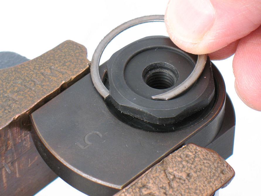
1 Disassembly Instructions - Dynorbital EXTREME Models: All Important: Disconnect sander from the air supply. Notice: Use these instructions along with the tool manual. To avoid damage, use the special repair tools designed for motor disassembly and assembly. Position Repair Collar around the housing. Fasten sander in vise with sanding pad facing up. Do not over tighten sander in vise. Use Wrench (26 mm) to hold the balancer shaft stationary. To remove sanding pad, turn counterclockwise.
2 Motor Disassembly: 1. Use Lock Ring Wrench to remove Lock Ring. Turn counterclockwise.

3 2. Remove motor from housing. Remove O-Ring from Cylinder Sleeve Adapter.
 with counterweight pointing down.")
4 3. Fasten Bearing Separator (2") around Cylinder Sleeve. Place bearing separator and motor in Arbor Press (#2) with counterweight pointing down. Use arbor press and 5/16" or 8 mm diameter flat-end drive punch to push shaft out of Bearing.

5 4. Use Bearing Removal Tool to remove Bearing from Rear Bearing Plate.

6 5. Remove vanes, rotor and key.

7 6. Use bearing separator and arbor press to remove the front bearing plate and seal.

8 7. Fasten bearing separator between Bearing and the counterweight. Place bearing separator in arbor press with counterweight pointing down. Push shaft balancer from Bearing. Motor disassembly completed.

9 Balancer Shaft and Bearing Disassembly: 1. Fasten counterweight in vise with hex of Balancer Shaft pointing up. Use a thin slot-blade screwdriver as a pick to remove Snap Ring. (Next three views.)
10

11 2. To break adhesive bond, use two, large slot-blade screwdrivers to pry out balancer shaft and bearing. Notice: If necessary, use a HEAT GUN to warm counterweight to soften adhesive.

12 3. Use Bearing Puller to remove balancer shaft and Bearing.

13 4. Fasten bearing separator between Bearing and hex end of balancer shaft.

14 5. Place bearing separator and balancer shaft in arbor press with hex end pointing down. Use the arbor press to break the adhesive bond.

15 6. Use a 5/16" or 8 mm diameter flat-end drive punch as a press tool to push balancer shaft out of Bearing.

16 Balancer shaft and bearing disassembly completed. Clean and inspect parts before assembling. Assembly Instructions - Dynorbital EXTREME

17 Balancer Shaft and Bearing Assembly: 1. Install Snap Ring onto Seal.

18 2. Install Seal and Snap Ring onto Balancer Shaft. Notice: Position flat side of seal toward Bearing. Apply a small amount of Loctite #271 or equivalent to outside diameter of balancer shaft.

19 3. Use small diameter of Bearing Press Tool and arbor press to install Bearing. Notice: Position sealed side of bearing toward Seal. Press bearing to step on shaft.

20 4. Apply a small amount of Loctite #271 or equivalent to outside diameter of Bearing. Install balancer shaft with bearing into shaft balancer.

21 5. Use a thin slot-blade screwdriver to compress and install Snap Ring into groove of shaft balancer. Balancer shaft and bearing assembly completed.

22 Motor Assembly: 1. Install Felt Washer into Front Bearing Seal. Install onto shaft balancer.

23 2. Use small diameter of Bearing Press Tool and arbor press to install Bearing onto shaft balancer.


24 3. Use large diameter end of Bearing Press Tool, and arbor press to install Front Bearing Plate. 4. Carefully fit plate to the bearing, felt washer and front bearing seal. Notice: The felt washer should be completely retained in the front bearing seal.

25 5. Install Key and rotor onto shaft balancer. 6. Apply Dynabrade Air Lube 10W/NR or equivalent to vanes and install.


26 7. Install O-Ring into Cylinder Sleeve Adapter. Line-up tab on cylinder sleeve adapter with small slot in Cylinder Sleeve. 8. Install Cylinder Sleeve and Cylinder Sleeve Adapter so that short pins fit into front bearing plate.

27 9. Use RAISED OUTSIDE DIAMETER of Bearing Press Tool and arbor press to install Bearing into Rear Bearing Plate.

28 10. Use RAISED INSIDE DIAMETER of Bearing Press Tool and arbor press to install bearing and plate onto shaft balancer. Notice: Carefully press bearing/plate down until it just touches the cylinder. This will produce a close fit between the bearing plates and cylinder sleeve. Apply oil to O-Ring and install into Cylinder Sleeve Adapter.
29 11. Install Lock Ring over counterweight. Sight line-up pin with notch inside housing. Keep finger pressure against lock ring and install motor.

30 12. Place Repair Collar around housing. Fasten sander in vise with counterweight pointing up. Notice: Do not over tighten sander in vise or it will be difficult to install Lock Ring. Use Lock Ring Wrench to tighten lock ring. Turn clockwise. Torque to 23 N m/~200 lbs. in. Motor assembly completed. To install sanding pad, use Wrench (26 mm.) to hold balancer shaft stationary. Turn pad clockwise. IMPORTANT: To verify the correct RPM and tool performance, follow instructions on page 2 of tool manual. Refer to: Maintenance Schedule - Every 20 Hours/Once a Week - First Bullet: Measure RPM and follow the instructions. Vacuum & Exhaust Assemblies: To identify vacuum and exhaust components, refer to exploded view and parts list found in tool manual.
Disassembly Instructions - 1 hp. Planetary Reduction Gears
 Disassembly Instructions - 1 hp. Planetary Reduction Gears Important: Use these instructions along with the tool parts page or manual. Notice: To avoid damage to the motor housing, use the Special Repair
4.2 - PUMP MAINTENANCE MODELS: AC, AS, WC, WS
 4.2 - PUMP MAINTENANCE MODELS: AC, AS, WC, WS 4.2.1 - EXPLODED VIEW DRAWING REF NO. 1 2 4 QTY 3 1 1.5 5 ¾ HP HP HP HP HP DESCRIPTION PART # 1 CASE 1.25 x 1 NPT 018266 1 CASE 1.25 X 1 NPT 018268 1 CASE
5.Use Spray gasket glue or Silicone Sealant on 1214 Valve Plate. When tacky, place on motor block with 1225 timing plate towards front.
 Assembly 2000 1.Press on 1241S Counterweight Guards onto 1215 Motor Block. The end with the hole goes towards the center. Note slot on top of 1215 Block always goes towards the front. Put 1212S Rings on
ELECTRIC TOOL CORPORATION
 Cat. No. -0 / Hex Demolition Hammer Cat. No. 0-0 Spline Rotary Hammer MILWAUKEE ELECTRIC TOOL CORPORATION W. LISBON ROAD BROOKFIELD, WISCONSIN 00-0 -9-00 d 000 -9-00 d SpecialTools Require Forcing discs
HDL(M)6 Nut/Screw Assembly
6 Nut/Screw Assembly") HDL(M)6 Nut/Screw Assembly Remove, repair, and reassemble the nut and screw assembly in your HDL series double lock vise. In these instructions when we refer to the front of the vise or nut/screw assembly,
HDL(M)6 Nut/Screw Assembly Remove, repair, and reassemble the nut and screw assembly in your HDL series double lock vise. In these instructions when we refer to the front of the vise or nut/screw assembly,
Maintenance Information
 16601023 Edition 2 January 2014 Air Impact Wrench 2705P1 Maintenance Information Save These Instructions Product Safety Information WARNING Failure to observe the following warnings, and to avoid these
REPAIR INSTRUCTIONS. Cat. No Cat. No MILWAUKEE ELECTRIC TOOL CORPORATION. SDS Max Demolition Hammer. SDS Max Rotary Hammer
 Cat. No. 9-0 SDS Max Demolition Hammer Cat. No. -0 SDS Max Rotary Hammer MILWAUKEE ELECTRIC TOOL CORPORATION W. LISBON ROAD BROOKFIELD, WISCONSIN 00-0 8-9-0 d 000 8-9-0 d Special Tools Require Forcing
TRAKFAST REPAIR MANUAL DANGER TOOL DISASSEMBLY ALWAYS TAKE THE FOLLOWING PRECAUTIONS BEFORE ANY SERVICE OR ROUTING MAINTENANCE IS PERFORMED:
 DANGER ALWAYS TAKE THE FOLLOWING PRECAUTIONS BEFORE ANY SERVICE OR ROUTING MAINTENANCE IS PERFORMED: REMOVE FASTENERS REMOVE FUEL CELL REMOVE BATTERY REMOVE THE MAGAZINE ASSEMBLY Loosen and remove knob
MODEL SK61732 COMPRESSOR SERVICE KIT
 MODEL SK61732 COMPRESSOR SERVICE KIT For use on 607 and 617 Model Compressors with.32 Stroke WARNING: Unplug the compressor before beginning disassembly. CAUTION: Improper assembly or use of damaged parts
Midwest RDH Handpiece Repair Procedure
 Midwest RDH Handpiece Repair Procedure The Midwest RDH handpiece is fairly common and is used by hygienists to clean teeth. The most common problems for this handpiece include a bad prophy head or a dirty
DRIVE COMPONENTS REMOVAL. 9. FXCW/C: see Figure Remove bolt (9), sprocket retainer (8), and thrust washer (7). NOTE PRIMARY DRIVE LOCKING TOOL
, sprocket retainer (8), and thrust washer (7). NOTE PRIMARY DRIVE LOCKING TOOL") DRIVE COMPONENTS REMOVAL PART NUMBER HD-7977 TOOL NAME PRIMARY DRIVE LOCKING TOOL S To remove the primary chain, remove compensating sprocket, clutch assembly and primary chain as an assembly:. Remove
DRIVE COMPONENTS REMOVAL PART NUMBER HD-7977 TOOL NAME PRIMARY DRIVE LOCKING TOOL S To remove the primary chain, remove compensating sprocket, clutch assembly and primary chain as an assembly:. Remove
RTI TECHNOLOGIES, INC.
 RTI TECHNOLOGIES, INC. BRC500 & BRC550 Arbor/Spindle Mechanism Adjustment & Service Technical Instructions The arbor/spindle mechanism of the BRC500/550 is designed to be robust for long life. Occasionally
OPERATION AND MAINTENANCE FOR MODEL MRV050A REVERSIBLE
 OPERATION AND MAINTENANCE FOR MODEL MRV050A REVERSIBLE MANUAL AIR MOTOR 04666770 Edition 1 April, 1999 IMPORTANT SAFETY INFORMATION ENCLOSED. READ THIS MANUAL BEFORE OPERATING TOOL. FAILURE TO OBSERVE
Maintenance Information
 47104302 Edition 1 November 2012 Cordless Drill/Driver QX Series Maintenance Information Save These Instructions Tool Diagnosis 1. Before servicing this unit, you will need a fully charged battery of known
TorqueMaster Replacement Spring
 TorqueMaster Replacement Spring Installation Instructions NOTE: Use these installation instructions in conjunction with the TorqueMaster Repair / Replacement Spring Program literature. Copyright 999 Wayne-Dalton
OTECO INC. MODEL ,000 PSI 4-1/16 PORT DM GATE VALVE MAINTENANCE MANUAL
 Page 1 of 7 OTECO INC. MODEL 45 4 5,000 PSI 4-1/16 PORT DM GATE VALVE MAINTENANCE MANUAL Page 2 of 7 TABLE OF CONTENTS 1. Assembly Blowout 2. Repair Kit Contents & Technical Specifications 3. Disassembly
Series Inline Oscillating Saw
 Parts Manual Ersatzteil Liste 45-8185 12-2065 Series Inline Oscillating Saw IMPORTANT: Read and comply with safety and operating instructions contained in this manual. For additional product information
BRAVO STERN DRIVE 3 C BRAVO ONE
 RAVO STERN DRIVE 3 C 22439 RAVO ONE Table of Contents Page Specifications............................... 3C-1 Torque Specifications..................... 3C-1 Preloads................................ 3C-1
SUPER PRO GUN & SUPER PRO GUN II
 MAGNUM VENUS PRODUCTS Maintenance & Repair Manual Part No. M6707-1-1 Revision 04.14.01 Maintenance & Repair Corporate HQ & Mfg. Phone: (727) 573-2955 Fax: (727) 571-3636 Email: info@magind.com Web: www.magind.com
MODELS 49 RA 49 RAZ 49 RAC
 General Safety and Maintenance Manual MODEL grinder featuring a rear exhaust. Model Number Exhaust Direction REAR Throttle Type (L) Lever or (K) Safety Lever Speed 12000 to 14000 R.P.M (13500rpm is standard)
Arc Trainer Main Frame Assembly
 Arc Trainer Main Frame Assembly Kit No. 610AK019-4 Kit No. 630AK019-4 NOTE: This instruction sheet describes how to replace the main frame assembly in the Arc Trainer 610A. Tools Required 3/16 Allen wrench
Thomas Scientific Swedesboro, NJ U.S.A.
 Thomas Scientific Swedesboro, NJ 08085-0099 U.S.A. Wiley Mini Mill 3383-L10 (115 V, 60 HZ) USE AND CARE OF CATALOG NUMBER: 3383-L10 Wiley Mini Mill (115 V, 60 HZ) PRELIMINARY 1. Mill has been properly
No September, Char-Lynn. Power Steering. Repair Information. 20 Series Steering Control Unit 001
 Char-Lynn Power Steering No. 7-313 September, 1997 Repair Information 20 Series Steering Control Unit 001 Bearing Race Retaining Ring Needle Thrust Bearing Bearing Race Seal Ring Backup Washer Seal (3
Page 1. SureMotion Quick-Start Guide: LARSACC_QS 1st Edition - Revision A 03/15/16. Standard Steel Bolt/Screw Torque Specifications
 R K C T I Repair Kit Product Compatibility Repair Kit # Linear Actuator Assembly # LARSACC-013 LARSACC-014 LARSD2-08T12BP2C (12-in travel) LARSD2-08T24BP2C (24-in travel) C P I R K 1 ea Ball Screw with
HEAVY DUTY CENTRIFUGAL PUMPS
 HEAVY DUTY CENTRIFUGAL PUMPS Supplemental Assembly Manual DryLock 1 Static Seal Cartridge 1. Place the slide rings (24A & 24B) into the bore of the rotary seal housing (24). The shortest slide ring goes
Series 760 Heavy Duty Fixed Displacement Motor. Parts and Repair Manual
 Series 760 Heavy Duty Fixed Displacement Motor Parts and Repair Manual Series 760 Fixed Displacement Motor Contents Introduction 3 ID Tag Information 3 Parts List 4 Parts Drawing 5 Disassembly Instructions
400 SERIES GRINDER PUMPS 41502, 42202,43302, AND MODELS
 Section: MOYNO 500 PUMPS Page: 1 of 6 Date: March 1, 1998 SERVICE MANUAL MOYNO 500 PUMPS 400 SERIES GRINDER PUMPS 41502, 42202,43302, AND 44402 MODELS DESIGN FEATURES Housing: Cast iron Pump Rotor: Chrome
Model 209 Fireback Replacement
 Model 209 Fireback Replacement Please read all the instructions before you begin the procedure. Confirm that you have all the necessary tools and materials. If you have any questions, technical support
Inspection. Assembly Install the springs. 1. Discard the 0-rings. 2. Clean all parts in cleaning solvent.
 6010-34 Inspection 3. Install the springs. 1. Discard the 0-rings. 2. Clean all parts in cleaning solvent. 3. If spring test equipment is available, check the tension of each spring according to the specifications
Removing and Replacing the Y-truck
 Service Documentation Removing and Replacing the Y-truck To remove and replace the Y-truck you will need the following tools: 4mm Allen wrench 12mm stamped flat wrench #2 Phillips screwdriver (magnetic
MS25 OPERATION MANUAL
 SAFETY INSTRUCTIONS SPECIFICATIONS OPERATING INSTRUCTIONS MAINTENANCE ADJUSTMENTS REPLACEMENT OF PARTS MS25 DIAGRAM MS25 PARTS LIST MS25 OPERATION MANUAL SAFETY INSTRUCTIONS Please read these instructions
E30 Limited Slip Clutch Disc Replacement
 E30 Limited Slip Clutch Disc Replacement Disclaimer: The instructions that follow were compiled by amateur mechanics, with input from a few engineers. There is no guarantee that your differential will
General Safety and Maintenance Manual
 General Safety and Maintenance Manual 4 H.P HORIZONTAL GRINDERS CAPACITY -6 Inch (150 mm) or 8 Inch (200 mm) Type 1 Wheels -Any Type 16, 17, 17R, 18 or 18R Cone Wheels w/ 5/8-11 Mounting 65H Series 4 H.P
Tail Rotor Spindle Assembly Repair Procedure
 Tail Rotor Spindle Assembly Repair Procedure Disassembly 1. Remove tail rotor assembly and blade assemblies in accordance with: a. TH28/480 Series MM-9-107 b. F-28F/280FX Series MM-10-2 2. Clamp spindle
3 Emergency Breakaway Coupling
 SM64227 July 2008 Applicable addition manuals: N/A Aerospace Group Conveyance Systems Division Carter Ground Fueling Maintenance & Repair Manual 3 Emergency Breakaway Coupling Model 64227 Table of Contents
Click Here to Go Back
 Click Here to Go Back Fig. -94 Fig. -97 CC42D 10. Remove the cap screw securing the gear shift stopper plate pin retainer; then remove the retainer. Fig. -95 CC45D 12. Remove the link arm and account for
OPERATIONAL MANUAL V1.0. Removing/Replacing Blades
 OPERATIONAL MANUAL V1.0 BLUEROCK WS-212 Wire Stripper Removing/Replacing Blades CAUTION!! IMPORTANT!! DANGER!! WARNING!! DISCONNECT MACHINE FROM POWER BEFORE PROCEEDING!! Estimated Completion Time: 90
AFB (AIR FAN BEARING) INSTALLATION GUIDE
 INSTALLATION GUIDE") 654 AFB (AIR FAN BEARING) INSTALLATION GUIDE AFB PARTS Bearing Housing - Secured together with two 3/8 x 1.25 in. Cap Screws Black Wiper Seals - Secured together with O-ring cord (Subsequently depicted
654 AFB (AIR FAN BEARING) INSTALLATION GUIDE AFB PARTS Bearing Housing - Secured together with two 3/8 x 1.25 in. Cap Screws Black Wiper Seals - Secured together with O-ring cord (Subsequently depicted
USSC LLC 4 ONE LLC FIELD MODIFICATION INSTRUCTIONS
 1 OF 17 A 1. PURPOSE: Instructions for in field replacement of 9004 mechanical suspension top pan 2. SCOPE: 9004 mechanical suspension with legacy two point LX back frame and current LX back frame 3. PROCEDURE:
Installation Instructions Precision Sport Shifter
 Installation Instructions Precision Sport Shifter 2004 and up Pontiac GTO Part Number 45043 2010, 2005, 2004 by B&M Racing and Performance Products This B&M Precision Sport Shifter has been designed to
WSG 8-115; 8-125; P; WSG ; WSG P; WSG PS; WSG P; WSG 15-70Inox
 Repair instructions Page of 47 Contents. Models described 2. Technical data 3. Notes and requirements 4. Tools required 5. Lubricants and auxiliary substances required 6. Disassembly 7. Assembly 8. Connection
JARVIS. Model Brisket Scissor EQUIPMENT... TABLE OF
 Model 423-17 Brisket Scissor EQUIPMENT SELECTION... Ordering No. TABLE OF CONTENTS... Page Model 423--17... 4037003 Air Filter / Regulator / Lubricator 3022003 Air Hose Assembly... 3059018 Balancer...
#4500 BULLET SIZER & LUBRICATOR
 #4500 BULLET SIZER & LUBRICATOR Assembly Your new #4500 Bullet Sizer and Lubricator has been fully assembled at the factory, However, to facilitate packaging and shipping, the handle has been dismounted.
Power Train Lift Max. Capacity: 1,250 lbs.
 655 EISENHOWER DRIVE OWATONNA, MN 55060 USA PHONE: (507) 455-7000 TECH. SERV.: (800) 533-6127 FAX: (800) 955-8329 ORDER ENTRY: (800) 533-6127 FAX: (800) 283-8665 INTERNATIONAL SALES: (507) 455-7223 FAX:
LU6X-130 Instructions and Parts List (including LU6X Basic) Operating Instructions
 Operating Instructions") LORTONE LU6X-130 Item # 061-092 LU6X Basic Item # 061-090 LU6X-130 Instructions and Parts List (including LU6X Basic) Operating Instructions Introduction The LU6X is one the most versatile pieces of equipment
LORTONE LU6X-130 Item # 061-092 LU6X Basic Item # 061-090 LU6X-130 Instructions and Parts List (including LU6X Basic) Operating Instructions Introduction The LU6X is one the most versatile pieces of equipment
H4670/42192 Submersible Trash Pump
 SERVICE MANUAL H4670/42192 Submersible Trash Pump Serial Code GLW Read and understand all of the instructions and safety information in this manual before operating or servicing this tool. 99916070 REV
1. Turn off or disconnect power to unit (machine). 2. Push IN the release bar on the quick change base plate. Locking latch will pivot downward.
. 2. Push IN the release bar on the quick change base plate. Locking latch will pivot downward.") Figure 1 Miniature Quick Change Applicators, of the end feed type, are designed to crimp end feed strip terminals to prestripped wires. Each applicator is set up to accept the strip form of certain specific
Figure 1 Miniature Quick Change Applicators, of the end feed type, are designed to crimp end feed strip terminals to prestripped wires. Each applicator is set up to accept the strip form of certain specific
H6400, H6400C1 & VSD6400 REVERSIBLE DRILLS
 SERVICE MANUAL H6400, H6400C1 & VSD6400 REVERSIBLE DRILLS Read and understand all of the instructions and safety information in this manual before operating or servicing this tool. 999 1801.3 REV 4 2001
H8508 Impact Wrench SERVICE MANUAL. Model (Serial Code FWN) Model (Serial Code FWP)
 Model (Serial Code FWP)") SERVICE MANUAL H8508 Impact Wrench Model 48755 (Serial Code FWN) Model 48760 (Serial Code FWP) Read and understand all of the instructions and safety information in this manual before operating or servicing
SERVICE MANUAL H8508 Impact Wrench Model 48755 (Serial Code FWN) Model 48760 (Serial Code FWP) Read and understand all of the instructions and safety information in this manual before operating or servicing
RATCHET CABLE CUTTER
 OPERATION, SERVICE AND PARTS INSTRUCTION MANUAL 764 RATCHET CABLE CUTTER Read and understand this material before operating or servicing this equipment. Failure to understand how to safely operate this
2. Inspect the end yoke bores for wear and damage. Replace if necessary.
 SERVICE INSTRUCTIONS BEFORE DOING ANY SERVICE OR MAINTENANCE WORK ON THE MACHINE, YOU MUST: Disengage all power Shut off the tractor engine LOOK and LISTEN! Make sure all moving parts are stopped. Disconnect
PROPELLER SHAFT PR 3 COMPONENTS
 PR3 COMPONENTS PR4 REMOVAL OF 1. DISCONNECT FRONT (a) Place the matchmarks on the both flanges. (b) Remove the four bolts, washers and nuts. (c) Pull the yoke from the transfer. (d) Insert SST in the transfer
w w w. h d o n l i n e s h o p. d e TIMKEN BEARING CONVERSION TOOL GENERAL INSTALLATION -J04672 REV Kit Number Models
 -J067 REV. 008-07- GENERAL Kit Number 8-08 Models TIMKEN BEARING CONVERSION TOOL For model fitment information, see the P&A Retail Catalog or the Parts and Accessories section of www.harley-davidson.com
PULL-THRU USER S MANUAL
 PULL-THRU USER S MANUAL G14x Part # 310 120 177 G20 Part # 310 120 188 G20x Part # 310 120 186 G40x Part # 310 120 163 TABLE OF CONTENTS SECTION 1 PCB DESIGN AND MOUNTING SECTION 2 MOUNTING ADAPTER TO
4.4 PUMP MAINTENANCE MODELS: DB, DC, DF, DG, DJ, DL
 4.4 PUMP MAINTENANCE MODELS: DB, DC, DF, DG, DJ, DL 4.4.1 EXPLODED VIEW DRAWING REF. QTY. DB DC DF DG DJ DL DESCRIPTION PART # 1 1 ADAPTOR FRAME 034007 2 12 LOCK WASHER 3/8 x 1/8 S.S. 034004 3 12 HEX HEAD
MECHANICAL ASSEMBLY John Wiley & Sons, Inc. M. P. Groover, Fundamentals of Modern Manufacturing 2/e
 MECHANICAL ASSEMBLY Threaded Fasteners Rivets and Eyelets Assembly Methods Based on Interference Fits Other Mechanical Fastening Methods Molding Inserts and Integral Fasteners Design for Assembly Mechanical
Rev B C-RING TOOL VA0375 ½ in. OPERATING MANUAL
 Rev B 4-30-0 C-RING TOOL VA0375 ½ in. OPERATING MANUAL Operational Instructions for Vertex C-Ring Tool VA0375 Vertex Fasteners is committed to providing our customers with world-class customer service
General Safety and Maintenance Manual 3 H.P HORIZONTAL GRINDERS. and Thread RPM T1-5/8-11 X 1.9. Lever. Lever. Handle
 HENRY TOOLS Industrial Airtools at Work General Safety and Maintenance Manual 3 H.P HORIZONTAL GRINDERS 3 H.P HORIZONTAL GRINDERS Capacity: -6 Inch (150 mm) or 8 Inch (200 mm) Type 1 Wheels -Any Type 16,
PROSTEER BALL JOINT REBUILD INSTRUCTIONS V1.0
 DYNATRAC PRODUCTS 2003-2010 4X4 DODGE 2500/3500 HEAVY DUTY BALL JOINT PROSTEER BALL JOINT REBUILD INSTRUCTIONS V1.0 WARNING: Improper use or installation of this product can cause major failures that could
SHEREX FASTENING SOLUTIONS PNEUMATIC SPIN-SPIN RIGHT ANGLE INLINE STYLE RIVET NUT INSTALLATION TOOL SSG-913 MANUAL
 SHEREX FASTENING SOLUTIONS PNEUMATIC SPIN-SPIN RIGHT ANGLE INLINE STYLE RIVET NUT INSTALLATION TOOL SSG-913 MANUAL SSG-913 Specifications R.P.M. - 400 *Air Pressure - 80-110 psi (oiled) Weight - 2.3 lbs.
Fisher 667 Diaphragm Actuators Size 80 and 100
 Instruction Manual 667 Size 80 and 100 Actuators Fisher 667 Diaphragm Actuators Size 80 and 100 Contents Introduction... 1 Scope of Manual... 1 Description... 2 Specifications... 2 Maximum Pressure Limitations...
30DC Speed Lathe Manual
 30DC Speed Lathe Manual The Crozier Model 30DC Speed Lathe is our most popular model. It has many standard features not found on any other machine in its class or price range. Standard Features 3/4 HP
Engineering Data Single Reduction Parts List Item # Description Basic Single Reduction Unit 1. Gear Housing 2. Pipe Plug 3. Vent Plug 4. Splash Guard
 Engineering Data Single Reduction Parts List Item # Description Basic Single Reduction Unit 1. Gear Housing 2. Pipe Plug 3. Vent Plug 4. Splash Guard 5. Input Cover 6. O-Ring 7. Hex Head Cap Screw 8. Input
SHEREX FASTENING SOLUTIONS PNEUMATIC SPIN-SPIN INLINE STYLE RIVET NUT INSTALLATION TOOL SSG-902 MANUAL
 SHEREX FASTENING SOLUTIONS PNEUMATIC SPIN-SPIN INLINE STYLE RIVET NUT INSTALLATION TOOL SSG-902 MANUAL SSG-902 Specifications R.P.M. - 1500 *Air Pressure - 60-90 psi (oiled) Weight - 2 lbs. (0.9 kg) Air
Pneumatic Drill / / Technical Specification
 CS UNITEC Pneumatic Drill 2 2502 0010 / 2 2502 0030 2 2506 0010 / 2 2506 0030 Technical Specification Model with Lever Throttle Model with Twist Throttle with Selfresetting 2 2502 0010 2 2502 0030 2 2506
Maintenance Information
 16575177 Edition 1 June 2006 Electric Angle Wrench QE8 Series Maintenance Information Save These Instructions General Instructions: Refer to Suggested Tools Parts List for quick reference to the tools
JARVIS. Model BR-3 Blade Reconditioner ... EQUIPMENT TABLE OF
 - Model BR-3 Blade Reconditioner EQUIPMENT SELECTION.......... Ordering No. TABLE OF CONTENTS............................ Page Model BR-3 (100 mm Blade) 115V/60Hz............ 4011003 220V/50Hz............
Crestline Dampening System. Installation Instructions. Shinohara 66. X /98 Rev-A 2598
 Crestline Dampening System Installation Instructions Shinohara 66 X88-58 8/98 Rev-A 2598 GENERAL INFORMATION ATTENTION CRESTLINE DAMPENER OWNER! Accel Graphic Systems provides parts and service through
Installation Instructions
 The IMS ETERNAL FIX PATENT PENDING Installation Instructions EPS recommends professional installation for the Eternal IMS Fix. Please take all precautionary safety measures. We also recommend putting the
JARVIS. Model25CL-4,5,6 Hock Cutter and Loin Dropper. 25CL--5 Front Legs and Horns. 25CL--4 Hind Legs and Horns. 25CL--6 Loins
 Model25CL-4,5,6 Hock Cutter and Loin Dropper 25CL--4 Hind Legs and Horns 25CL--5 Front Legs and Horns 25CL--6 Loins EQUIPMENT SELECTION... Ordering No. TABLE OF CONTENTS... Page 25CL--4... 4025007 25CL--5...
Electric Skein Winder
 Electric Skein Winder Assembly and Use Package Contents 1 - Triangular Body (w/ motor) 1 - Cross Arm 1 - Left Foot (w/ yarn guide) 1 - Right Foot 1 - Adjustable Finger (w/ yarn clip) 3 - Adjustable Fingers
General Safety and Maintenance Manual
 General Safety and Maintenance Manual 3 H.P HORIZONTAL GRINDERS CAPACITY -6 Inch (150 mm) or 8 Inch (200 mm) Type 1 Wheels -Any Type 16, 17, 17R, 18 or 18R Cone Wheels w/ 5/8-11 Mounting 3 H.P HORIZONTAL
Power Output. Spindle. 7.7 Inches (196 cm) 11.0 Lbs. (5.0 Kg)
 11.0 Lbs. (5.0 Kg)") HENRY TOOLS Industrial Airtools at Work General Safety and Maintenance Manual SUPER HEAVY DUTY VERTICAL GRINDERS 4 Horsepower Vertical Grinders 4 HORSEPOWER Model Number Throttle Type Power Output Weight
HENRY TOOLS Industrial Airtools at Work General Safety and Maintenance Manual SUPER HEAVY DUTY VERTICAL GRINDERS 4 Horsepower Vertical Grinders 4 HORSEPOWER Model Number Throttle Type Power Output Weight
1904, 1904Pg, 1904PgSB, and 1906SB High Capacity Ratchet Knockout Drivers
 INSTRUCTION MANUAL 1904, 1904Pg, 1904PgSB, and 1906SB High Capacity Ratchet Knockout Drivers Read and understand all of the instructions and safety information in this manual before operating or servicing
INSTALLATION OF WELLS SUPER QUICK CHUCK LEFT HAND ON RED WING LATHE
 DENTAL, INC. TECHNICAL BULLETIN Q824-022510 5860 FLYNN CREEK ROAD READ ALL INSTRUCTIONS P.O. BOX 106 BEFORE PROCEEDING COMPTCHE, CALIFORNIA, U.S.A. 95427 SAVE THIS FOR FUTURE REFERENCE www.wellsdental.com
Model LS1018 Parts List A = Standard Equipment 〇 = Circuit Diagram
 LS1018 7-14 103 104 105 106 97 99 100 110 109 63 85 96 200 107 90 2 199 108 37 89 91 92 93 94 31 74 75 73 140 70 121 15 254 255 113 215 236 116 114 115 196 258 195 118 197 119 259 117 203 253 67 95 112
POWERNAIL CO. Seal Kit Replacement Guide. Seal Kit for all Pneumatic Nailers: # A (Includes 1 of each seal for a pneumatic rebuild)
") POWERNAIL CO. Seal Kit Replacement Guide Seal Kit for all Pneumatic Nailers: # 09-200-3058A (Includes 1 of each seal for a pneumatic rebuild) Model 200 Model 445 445SN Surface Nailer Models: 445 FLEX Power
POWERNAIL CO. Seal Kit Replacement Guide Seal Kit for all Pneumatic Nailers: # 09-200-3058A (Includes 1 of each seal for a pneumatic rebuild) Model 200 Model 445 445SN Surface Nailer Models: 445 FLEX Power
INSTALLATION MANUAL FRONT. See pages 2 and 3 of this manual for configuration options. Level of Difficulty. Product Photo (center section only)
") INSTALLATION MANUAL FRONT Level of Difficulty Moderate Product Photo (center section only) All hardware listed below will be provided with the bumpers center section. Additional hardware will be supplied
INSTALLATION MANUAL FRONT Level of Difficulty Moderate Product Photo (center section only) All hardware listed below will be provided with the bumpers center section. Additional hardware will be supplied
MicroHAWK Accessory Guide
 This guide contains instructions for how to install the following accessories on a MicroHAWK ID-20, ID-30, or ID-40 Reader, or on a MicroHAWK MV-20, MV-30, or MV-40 Smart Camera: Kit, Diffuser, MicroHAWK
MOTOR & BULK HEAD. A Manual for Repair and Maintenance Technicians
 MOTOR & BULK HEAD A Manual for Repair and Maintenance Technicians CAUTION This manual is designed to help technicians who are already experienced in workshop procedures and know how to handle tools. Only
Tools: Sharpie, Square, Vise, Hack saw, Ruler, Punch, Hammer, File. 2. Cut the stock Place stock in vise and cut with hack saw
 Purpose: MAKE CATAPULT ARM Step 1 Tools: Sharpie, Square, Vise, Hack saw, Ruler, Punch, Hammer, File Materials: Flat aluminum ½ inch stock (see picture below) Gloves required 1. Pick up the aluminum ½
LORON SERVICE MANUAL / PARTS LIST SINGLE DOUBLE PALLET HANDLER CONTENTS: PAGE 1 Lift Truck Requirements General Installation Procedures
 LORON SERVICE MANUAL / PARTS LIST SINGLE DOUBLE PALLET HANDLER CONTENTS: PAGE 1 Lift Truck Requirements General Installation Procedures 2 Mounting Options Stop Block Adjustments 3 General Weekly Inspection
Installation Instructions for Vista Air Vertically Folding Walls
 Installation Instructions for Vista Air Vertically Folding Walls Use these instructions in conjunction with your shop drawings to see the specifics that are particular to the model you are installing.
Gauge and ICM, ICM Tx, ICM TxR, and HUD Transmitter: AirHawk II Air Mask
 Gauge and ICM, ICM Tx, ICM TxR, and HUD Transmitter: AirHawk II Air Mask MAINTENANCE AND REPAIR MSA 713 (L) Rev. 1 MSA 2017 Prnt. Spec. 10000005389(I) Mat. 10104244 Doc. 10104244 Standard Gauge Item P/N
COYOTE ENTERPRISES, INC. RIMLOC BLAST WHEEL MAINTENANCE & ASSEMBLY MANUAL
 COYOTE ENTERPRISES, INC. RIMLOC BLAST WHEEL MAINTENANCE & ASSEMBLY MANUAL Parts & Machinery for the Abrasive Blast Industry 27301 East 121st Street Coweta, Oklahoma 74429 (918) 486-8411 Fax (918) 486-8412
Smart Sifter Vertical Shaft & Splined Coupler Replacement Manual
 Smart Sifter Vertical Shaft & Splined Coupler Replacement Manual Company: Norvell Company Inc. Phone: 800-653-3147 Fax: 620-223-3115 Date: Sept. 2014, Rev. #2 This manual is for our customers who wish
Pickup Box Utility Rack Package Installation (Instruction ID: )
") 017 Chevrolet Colorado Pickup - WD (VIN S) Canyon, Colorado Accessory Installation Manual N America Document ID: 3966961 Pickup Box Utility Rack Package Installation (Instruction ID:3144879) Installation
017 Chevrolet Colorado Pickup - WD (VIN S) Canyon, Colorado Accessory Installation Manual N America Document ID: 3966961 Pickup Box Utility Rack Package Installation (Instruction ID:3144879) Installation
Side Winder R o u t e r L i f t.
 Woodpeckers PRECISION WOODWORKING TOOLS Side Winder R o u t e r L i f t. INSTALLATION INSTRUCTIONS The wrench handle must be pointing left in order to fully insert or remove it. Lift Wrench Once fully
THE T-MAG II PRESS. Figure 6
 THE T-MAG II PRESS The Lyman T-Mag Press features a powerful compound leverage with a unique position indexable turret and quick disconnect release system. This allows you to mount several die sets, precisely
Inventory (Figure 2)
") MODEL T10127 12" SPIRAL CUTTERHEAD INSTRUCTIONS The Model T10127 indexable insert spiral cutterhead is designed to replace the straightknife cutterhead from the Grizzly jointer Model G0609. The total procedure
MODEL T10127 12" SPIRAL CUTTERHEAD INSTRUCTIONS The Model T10127 indexable insert spiral cutterhead is designed to replace the straightknife cutterhead from the Grizzly jointer Model G0609. The total procedure
TECHNICAL INFORMATION
 TECHNICAL INFORMATION P 1 / 11 Model No. Description CONCEPT AND MAIN APPLICATIONS Specification Standard equipment TCT saw blade... 1 Rear table set (exclusively Europe, Turkey, South Africa..1 2704 This
BETTIS SERVICE INSTRUCTIONS FOR MODELS G01 THROUGH G10 SERIES HYDRAULIC SPRING RETURN ACTUATORS WITH M11 HYDRAULIC OVERRIDE
 ENGLISH LANUAGE BETTIS SERVICE INSTRUCTIONS FOR MODELS G01 THROUGH G10 SERIES HYDRAULIC SPRING RETURN ACTUATORS WITH M11 HYDRAULIC OVERRIDE PART NUMBER: 127072E REVISION: A DATE: December 2001 Page 1 of
LISTA DE REFACCION MODELO LS1018L PAGINA 1. Pos. NUMERO DESCRIPCION Cant. NOTA
 PAGINA 1 001 JM23100006 CROSS HEAD SCREW M5X20 2 002 JM23100007 FLAT WASHER 5 2 003 JM23100008 PAD 4 004 JM23100009 LOCKNUT M10 1 005 JM23100010 FLAT WASHER 10 2 006 JM23100300 BASE COMPLETE 1 INC. 7 007
Installing flat panels on the MPL15 wall mount
 Installing flat panels on the MPL15 wall mount The MPL15 (DS-VW775) is a full-service video wall mount that can accommodate tiled LCD panels with up to a 400 x 400 mm VESA pattern in portrait and landscape
AR-15 Lower Receiver Assembly Instructions
 AR-15 Lower Receiver Assembly Instructions Tools There are a few tools that make it easier to put together these kits, but none of them are necessary. Minimum requirements include a hammer and punch to
DYNATRAC BALL JOINT REBUILD INSTRUCTIONS V4.0
 DYNATRAC PRODUCTS 2007-2016 4X4 JEEP JK HEAVY DUTY BALL JOINT JP44-2X3050-C DYNATRAC BALL JOINT REBUILD INSTRUCTIONS V4.0 WARNING: Improper use or installation of this product can cause major failures
5000 Series Single Impeller Firefighter
 5000 Series Single Impeller Firefighter Pump made in Australia & fitted to genuine brand name engines SERVICING INSTRUCTIONS WARNING: ALL ELECTRICAL WORK TO BE PERFORMED BY SUITABLY QUALIFIED ELECTRICAL
Char-Lynn Hydraulic Motor. Repair Information. R Series General Purpose Geroler Motor November, 1996
 Char-Lynn Hydraulic Motor November, 1996 Repair Information General Purpose Geroler Motor 001 002 2 Geroler Motors Parts Drawing Bearing Race Needle Thrust Bearing Key Output Shaft Cap Screw -001 12 pt
Tapping Screw (W/Flange) 46 Cord Armor 47 Tube (D) 48 Cord. 45 Cord Clip. Tapping Screw (W/Flange) 10 Gear Cover Ass'y. 12 Socket (B) Ass'y
 46 Cord Armor 47 Tube (D) 48 Cord. 45 Cord Clip. Tapping Screw (W/Flange) 10 Gear Cover Ass'y. 12 Socket (B) Ass'y") W8VB The exploded assembly drawing should be used only for authoized service center. W8VB Item No. Part time 1 Magnetic Hex. Socket 2 Sub Stopper 3 O-Ring (S-16) 4 Locator (A) 5 Lock Sleeve (A) 6 O-Ring
W8VB The exploded assembly drawing should be used only for authoized service center. W8VB Item No. Part time 1 Magnetic Hex. Socket 2 Sub Stopper 3 O-Ring (S-16) 4 Locator (A) 5 Lock Sleeve (A) 6 O-Ring
Tidland Slitter Shafts
 TIDLAND SLITTING SOLUTIONS Tidland Slitter Shafts Installation, Operation and Maintenance EN MI 666265 1 D Knife Shaft (tubular) KT Knife Shaft (solid) KS Anvil Roll (KS with sleeves) AR IMPORTANT SAFETY