Disassembly Instructions - 1 hp. Planetary Reduction Gears
|
|
|
- Hugo Reynolds
- 6 years ago
- Views:
Transcription

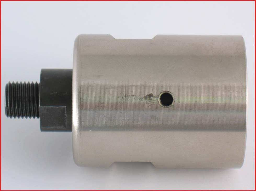
1 Disassembly Instructions - 1 hp. Planetary Reduction Gears Important: Use these instructions along with the tool parts page or manual. Notice: To avoid damage to the motor housing, use the Special Repair Tools designed for the disassembly and assembly of this motor. Disconnect the tool from the air supply. Use the appropriate wrenches to hold the work spindle stationary and remove the accessory. Planetary Gear Disassembly: Repair Collar 1. Position the Repair Collar around the motor housing. Fasten the tool in a vise so that the work spindle is pointing up. Use a HEAT GUN to warm the planetary gear casing or planetary cover to soften the thread adhesive.

2 Use an adjustable wrench to remove the planetary gear casing or planetary cover. Turn counterclockwise. IMPORTANT: Use "Disassembly Instructions - 1 hp. Straight" for repairing the air motor assembly.

3 2. Use a 2.5 mm or 3/32" hex key to remove the setscrew.


4 3. Remove the planetary reduction.
 with the FLAT SIDE")

5 BEVELED SIDE TOWARD THE BEARING 4. Important: Fasten the Bearing Separator (2") with the FLAT SIDE facing the RING GEAR and the BEVELED SIDE facing the Bearing. Place the bearing separator and the planetary reduction in the Arbor Press (#2) with the spindle pointing down.

6 5. Use a 5/8" or 16 mm diameter press tool to push the planetary carrier out of the Bearing. Remove the ring gear, shafts, and planet gears.

7 6. Fasten the planetary carrier in a vise with aluminum or bronze jaws so that the spindle nut is pointing up. Use an adjustable wrench to remove the spindle nut. Turn counterclockwise.

8 8. Use the arbor press to push the planetary carrier out of the Bearing.

9 Planetary Gear Disassembly Complete. Clean and inspect parts before assembling.


10 Planetary Gear Assembly: Assembly Instructions - 1 hp. Planetary Reduction Gears 5/8" or 16 mm deep well socket 1. Use 5/8" or 16 mm diameter deep well socket and the arbor press to install the Bearing onto the front of the planetary carrier.

11 Loctite # Fasten the planetary carrier in the vise with aluminum or bronze jaws so that the spindle is pointing up. Apply a small amount of Loctite #271 or equivalent to the thread for the spindle nut.


12 T to 17 N m/~150 in. lbs. Install the Spindle Nut onto the planetary carrier. Use a 19 mm crowfoot and torque wrench to tighten the spindle nut. (T to 17 N m/~150 in. lbs.)

13 Use Lubricant Gun to apply Grease or equivalent to needle bearings. 3. Apply the Grease or equivalent to the needle bearings in the planet gears.

14 Install the planet gears and the Shafts into the carrier.


15 Install the ring gear so that the notches will line-up with the lubricant and setscrew holes in the planetary gear casing or planetary cover.

16 JUST TOUCH 4. Use 5/8" or 16 mm diameter deep well socket and the arbor press to install the Bearing onto the planetary carrier. IMPORTANT: Carefully press the bearing to just touch the ring gear. This will establish a close fit between the bearings and the ring gear.

17 5. Install the planetary reduction into the planetary gear casing or planetary cover.
18
 and")
19 Loctite #567 Apply Loctite #567 or equivalent to the Setscrew(s) and install.

20 Loctite # Apply Loctite Primer #7649 or equivalent to the housing thread.

21 Loctite Loctite # #567 Apply a small amount of Loctite #567 or equivalent to housing thread.

22 INCORRECT LINE-UP WITH THE MOTOR HOUSING ASSEMLBY! 7. Use the Repair Collar to hold the motor assembly in a vise so that the opening of the housing is pointing up. IMPORTANT: Make sure that the planetary reduction assembly is in-line with the motor pinion gear.
23 CORRECT LINE-UP WITH THE MOTOR HOUSING ASSEMBLY. 8. The planetary gear casing or planetary cover must thread straight onto the motor housing assembly.


24 T to 35 N m/~300 in. lbs. Use a 1-9 / 16 " crowfoot and torque wrench to tighten the planetary gear casing or planetary cover. (T to 35 N m/~300 in. lbs.) 9. Check and make sure that the spindle RPM is correct. Planetary Gear Assembly Completed. Install arbor and accessory. Notice: Apply the information provided in these instruction to all straight-line, extension, and right angle planetary gear assemblies. In addition, refer to the specific parts page or tool manual for each model and follow the exploded views. IMPORTANT: Use "Disassembly and Assembly Instructions - 1 hp. Straight" for repairing the air motor assembly.
To remove sanding pad, turn counterclockwise.
 Disassembly Instructions - Dynorbital EXTREME Models: All Important: Disconnect sander from the air supply. Notice: Use these instructions along with the tool manual. To avoid damage, use the special repair
BRAVO STERN DRIVE 3 C BRAVO ONE
 RAVO STERN DRIVE 3 C 22439 RAVO ONE Table of Contents Page Specifications............................... 3C-1 Torque Specifications..................... 3C-1 Preloads................................ 3C-1
Page 1. SureMotion Quick-Start Guide: LARSACC_QS 1st Edition - Revision A 03/15/16. Standard Steel Bolt/Screw Torque Specifications
 R K C T I Repair Kit Product Compatibility Repair Kit # Linear Actuator Assembly # LARSACC-013 LARSACC-014 LARSD2-08T12BP2C (12-in travel) LARSD2-08T24BP2C (24-in travel) C P I R K 1 ea Ball Screw with
ELECTRIC TOOL CORPORATION
 Cat. No. -0 / Hex Demolition Hammer Cat. No. 0-0 Spline Rotary Hammer MILWAUKEE ELECTRIC TOOL CORPORATION W. LISBON ROAD BROOKFIELD, WISCONSIN 00-0 -9-00 d 000 -9-00 d SpecialTools Require Forcing discs
REPAIR INSTRUCTIONS. Cat. No Cat. No MILWAUKEE ELECTRIC TOOL CORPORATION. SDS Max Demolition Hammer. SDS Max Rotary Hammer
 Cat. No. 9-0 SDS Max Demolition Hammer Cat. No. -0 SDS Max Rotary Hammer MILWAUKEE ELECTRIC TOOL CORPORATION W. LISBON ROAD BROOKFIELD, WISCONSIN 00-0 8-9-0 d 000 8-9-0 d Special Tools Require Forcing
Tail Rotor Spindle Assembly Repair Procedure
 Tail Rotor Spindle Assembly Repair Procedure Disassembly 1. Remove tail rotor assembly and blade assemblies in accordance with: a. TH28/480 Series MM-9-107 b. F-28F/280FX Series MM-10-2 2. Clamp spindle
MODELS 49 RA 49 RAZ 49 RAC
 General Safety and Maintenance Manual MODEL grinder featuring a rear exhaust. Model Number Exhaust Direction REAR Throttle Type (L) Lever or (K) Safety Lever Speed 12000 to 14000 R.P.M (13500rpm is standard)
AFB (AIR FAN BEARING) INSTALLATION GUIDE
 INSTALLATION GUIDE") 654 AFB (AIR FAN BEARING) INSTALLATION GUIDE AFB PARTS Bearing Housing - Secured together with two 3/8 x 1.25 in. Cap Screws Black Wiper Seals - Secured together with O-ring cord (Subsequently depicted
654 AFB (AIR FAN BEARING) INSTALLATION GUIDE AFB PARTS Bearing Housing - Secured together with two 3/8 x 1.25 in. Cap Screws Black Wiper Seals - Secured together with O-ring cord (Subsequently depicted
1904, 1904Pg, 1904PgSB, and 1906SB High Capacity Ratchet Knockout Drivers
 INSTRUCTION MANUAL 1904, 1904Pg, 1904PgSB, and 1906SB High Capacity Ratchet Knockout Drivers Read and understand all of the instructions and safety information in this manual before operating or servicing
Page 1. SureMotion Quick-Start Guide: LACPACC_QS 1st Edition - Revision A 03/15/16
 R K C T I Repair Kit Product Compatibility Repair Kit # Linear Actuator Assembly # LACPACC-002 LACPACC-003 LACP-16TxxLP5 (0.5-in lead screw pitch) LACP-16TxxL1 (1-in lead screw pitch) C P I R K 4 ea Flanged
Midwest RDH Handpiece Repair Procedure
 Midwest RDH Handpiece Repair Procedure The Midwest RDH handpiece is fairly common and is used by hygienists to clean teeth. The most common problems for this handpiece include a bad prophy head or a dirty
Maintenance Information
 16575177 Edition 1 June 2006 Electric Angle Wrench QE8 Series Maintenance Information Save These Instructions General Instructions: Refer to Suggested Tools Parts List for quick reference to the tools
RATCHET CABLE CUTTER
 OPERATION, SERVICE AND PARTS INSTRUCTION MANUAL 764 RATCHET CABLE CUTTER Read and understand this material before operating or servicing this equipment. Failure to understand how to safely operate this
TURBO DRIVE INSTALLATION MODEL 1582T KNEE FEED Lagun Mill
 TURBO DRIVE INSTALLATION MODEL 1582T KNEE FEED Lagun Mill NOTE This Turbo Drive Knee Feed is configured for mounting the feed on the front of the knee with the keypad facing left. The lead screw pitch
H6400, H6400C1 & VSD6400 REVERSIBLE DRILLS
 SERVICE MANUAL H6400, H6400C1 & VSD6400 REVERSIBLE DRILLS Read and understand all of the instructions and safety information in this manual before operating or servicing this tool. 999 1801.3 REV 4 2001
TECHNICAL INFORMATION
 TECHNICAL INFORMATION P 1 / 11 Model No. Description CONCEPT AND MAIN APPLICATIONS Specification Standard equipment TCT saw blade... 1 Rear table set (exclusively Europe, Turkey, South Africa..1 2704 This
WSG 8-115; 8-125; P; WSG ; WSG P; WSG PS; WSG P; WSG 15-70Inox
 Repair instructions Page of 47 Contents. Models described 2. Technical data 3. Notes and requirements 4. Tools required 5. Lubricants and auxiliary substances required 6. Disassembly 7. Assembly 8. Connection
H8508 Impact Wrench SERVICE MANUAL. Model (Serial Code FWN) Model (Serial Code FWP)
 Model (Serial Code FWP)") SERVICE MANUAL H8508 Impact Wrench Model 48755 (Serial Code FWN) Model 48760 (Serial Code FWP) Read and understand all of the instructions and safety information in this manual before operating or servicing
SERVICE MANUAL H8508 Impact Wrench Model 48755 (Serial Code FWN) Model 48760 (Serial Code FWP) Read and understand all of the instructions and safety information in this manual before operating or servicing
4.2 - PUMP MAINTENANCE MODELS: AC, AS, WC, WS
 4.2 - PUMP MAINTENANCE MODELS: AC, AS, WC, WS 4.2.1 - EXPLODED VIEW DRAWING REF NO. 1 2 4 QTY 3 1 1.5 5 ¾ HP HP HP HP HP DESCRIPTION PART # 1 CASE 1.25 x 1 NPT 018266 1 CASE 1.25 X 1 NPT 018268 1 CASE
Zen Toolworks CNC Carving Machine DIY Kit User Installation Manual
 User Installation Manual Visit Us At: http://www.zentoolworks.com or http://www.zentoolworks.com/zenwiki/mediawiki Contact Us At: zentoolworks@gmail.com 1 P-01, Nema 17 Stepper Motor, 3 P-02, Motor Shaft
OTECO INC. MODEL ,000 PSI 4-1/16 PORT DM GATE VALVE MAINTENANCE MANUAL
 Page 1 of 7 OTECO INC. MODEL 45 4 5,000 PSI 4-1/16 PORT DM GATE VALVE MAINTENANCE MANUAL Page 2 of 7 TABLE OF CONTENTS 1. Assembly Blowout 2. Repair Kit Contents & Technical Specifications 3. Disassembly
Char-Lynn Hydraulic Motor. Repair Information. R Series General Purpose Geroler Motor November, 1996
 Char-Lynn Hydraulic Motor November, 1996 Repair Information General Purpose Geroler Motor 001 002 2 Geroler Motors Parts Drawing Bearing Race Needle Thrust Bearing Key Output Shaft Cap Screw -001 12 pt
SERVICE PARTS LIST PAGE 1 OF 6 BASE ASSEMBLY SPECIFY CATALOG NO. AND SERIAL NO. WHEN ORDERING PARTS 12" SLIDING COMPOUND MITER SAW
 PAGE 1 OF 6 BASE ASSEMBLY 00 0 CATALOG NO. EXAMPLE: SPECIFY CATALOG NO. AND NO. WHEN ORDERING PARTS 6955-20 1 02-80-0050 Thrust Bearing (1) 2 05-80-0510 M5 x 12mm Flat Head T-20 Screw (5) 3 05-81-0135
Gauge and ICM, ICM Tx, ICM TxR, and HUD Transmitter: AirHawk II Air Mask
 Gauge and ICM, ICM Tx, ICM TxR, and HUD Transmitter: AirHawk II Air Mask MAINTENANCE AND REPAIR MSA 713 (L) Rev. 1 MSA 2017 Prnt. Spec. 10000005389(I) Mat. 10104244 Doc. 10104244 Standard Gauge Item P/N
TURBO DRIVE INSTALLATION MODEL 1580T KNEE FEED Lagun Mill (OEM)
") TURBO DRIVE INSTALLATION MODEL 1580T KNEE FEED Lagun Mill (OEM) NOTE This Turbo Drive Knee Feed is configured for mounting the feed on the front of the knee with the keypad facing left. The lead screw
TURBO DRIVE INSTALLATION MODEL 1580T KNEE FEED Lagun Mill (OEM) NOTE This Turbo Drive Knee Feed is configured for mounting the feed on the front of the knee with the keypad facing left. The lead screw
No November, Char-Lynn. Hydraulic Motor. Repair Information. R Series General Purpose Geroler Motor
 Char-Lynn Hydraulic Motor No. 7-142 November, 1996 Repair Information General Purpose Geroler Motor 001 002 2 Geroler Motors Parts Drawing Bearing Race Needle Thrust Bearing Key Output Shaft Cap Screw
Inventory (Figure 2)
") MODEL T10127 12" SPIRAL CUTTERHEAD INSTRUCTIONS The Model T10127 indexable insert spiral cutterhead is designed to replace the straightknife cutterhead from the Grizzly jointer Model G0609. The total procedure
MODEL T10127 12" SPIRAL CUTTERHEAD INSTRUCTIONS The Model T10127 indexable insert spiral cutterhead is designed to replace the straightknife cutterhead from the Grizzly jointer Model G0609. The total procedure
SERVICE PARTS LIST PAGE 1 OF 6 BASE ASSEMBLY SPECIFY CATALOG NO. AND SERIAL NO. WHEN ORDERING PARTS 12" DUAL BEVEL COMPOUND MITER SAW B27B
 PAGE 1 OF 6 BASE ASSEMBLY 00 0 EXAMPLE: Component Parts (Small #) Are Included When Ordering The Assembly (Large #). SPECIFY CATALOG NO. AND NO. WHEN ORDERING PARTS = Part number change from previous service
Inventory (Figure 2)
") MODEL T24631 8" SPIRAL CUTTERHEAD Installation INSTRUCTIONS For questions or help with this product contact Tech Support at (570) 546-9663 or techsupport@grizzly.com Introduction The Model T24631 spiral
MODEL T24631 8" SPIRAL CUTTERHEAD Installation INSTRUCTIONS For questions or help with this product contact Tech Support at (570) 546-9663 or techsupport@grizzly.com Introduction The Model T24631 spiral
Submersible Turbine Assembly Manual
 Submersible Turbine Assembly Manual Table of Contents Submersible Turbine Kit Assembly Page Recommended Equipment... 2 Assembly Instructions...3-9 Special Tool Schematics... 10 Symbol Key Action Safety/Caution
TECHNICAL INFORMATION
 TECHNICAL INFORMATION Models No. 2012NB Description 304mm (12") Automatic Thickness Planer CONCEPTION AND MAIN APPLICATIONS * Compact and light weight (27 Kg./59 lbs) automatic thickness planer for easier
AT ADAPTER INSTALLATION INSTRUCTIONS
 IMPORTANT: THIS IS A HIGH PERFORMANCE PART AND IMPROPER INSTALLATION COULD RESULT IN INJURY OR DEATH! NEVER WORK UNDER AN AUTOMOBILE THAT IS NOT PROPERLY SUPPORTED AND BLOCKED FROM ROLLING. NO CREDIT OR
Inspection. Assembly Install the springs. 1. Discard the 0-rings. 2. Clean all parts in cleaning solvent.
 6010-34 Inspection 3. Install the springs. 1. Discard the 0-rings. 2. Clean all parts in cleaning solvent. 3. If spring test equipment is available, check the tension of each spring according to the specifications
MODEL H " BYRD SHELIX CUTTERHEAD INSTRUCTIONS
 MODEL H9291 12" BYRD SHELIX CUTTERHEAD INSTRUCTIONS The Model H9291 12" Byrd Shelix cutterhead is designed to replace the straight-knife cutterhead on the Grizzly jointer Model G0609. The total procedure
VARIABLE SPEED WOOD LATHE
 MODEL MC1100B VARIABLE SPEED WOOD LATHE INSTRUCTION MANUAL Please read and fully understand the instructions in this manual before operation. Keep this manual safe for future reference. Version: 2015.02.02
Referencing 0,0 position
 Page 1 of 11 TITLE: SABRE X-Axis Lead Screw Replacement Procedure Gerber FastFact #: 2013 Supplied by: Gerber Hardware Support Last Modified: March 1, 2011 Summary: The following procedure explains how
Installation Instructions Precision Sport Shifter
 Installation Instructions Precision Sport Shifter 2004 and up Pontiac GTO Part Number 45043 2010, 2005, 2004 by B&M Racing and Performance Products This B&M Precision Sport Shifter has been designed to
Series Inline Oscillating Saw
 Parts Manual Ersatzteil Liste 45-8185 12-2065 Series Inline Oscillating Saw IMPORTANT: Read and comply with safety and operating instructions contained in this manual. For additional product information
H4670/42192 Submersible Trash Pump
 SERVICE MANUAL H4670/42192 Submersible Trash Pump Serial Code GLW Read and understand all of the instructions and safety information in this manual before operating or servicing this tool. 99916070 REV
General Safety and Maintenance Manual
 General Safety and Maintenance Manual 4 H.P HORIZONTAL GRINDERS CAPACITY -6 Inch (150 mm) or 8 Inch (200 mm) Type 1 Wheels -Any Type 16, 17, 17R, 18 or 18R Cone Wheels w/ 5/8-11 Mounting 65H Series 4 H.P
Maintenance Information
 16601023 Edition 2 January 2014 Air Impact Wrench 2705P1 Maintenance Information Save These Instructions Product Safety Information WARNING Failure to observe the following warnings, and to avoid these
Maintenance Information
 47104302 Edition 1 November 2012 Cordless Drill/Driver QX Series Maintenance Information Save These Instructions Tool Diagnosis 1. Before servicing this unit, you will need a fully charged battery of known
HDL(M)6 Nut/Screw Assembly
6 Nut/Screw Assembly") HDL(M)6 Nut/Screw Assembly Remove, repair, and reassemble the nut and screw assembly in your HDL series double lock vise. In these instructions when we refer to the front of the vise or nut/screw assembly,
HDL(M)6 Nut/Screw Assembly Remove, repair, and reassemble the nut and screw assembly in your HDL series double lock vise. In these instructions when we refer to the front of the vise or nut/screw assembly,
DO35 MAINTENANCE INSTRUCTIONS
 CUSTOMER INFORMATION SHEET NO. 038 DO35 MAINTENANCE INSTRUCTIONS (DO35 V3 LAUNCHED PRODUCTION JUNE 2017) Table of Contents 1.0 Replacing Spindle Bushes V3... 22 2.0 Replacing Locking Mechanism V3... 6
TorqueMaster Replacement Spring
 TorqueMaster Replacement Spring Installation Instructions NOTE: Use these installation instructions in conjunction with the TorqueMaster Repair / Replacement Spring Program literature. Copyright 999 Wayne-Dalton
Publication Part No. SK
 Publication Part No. SK-463- Translating Tube Actuators Model Numbers M-464 & M-465 Rotating Screw Actuators Model Numbers M-46 & M-463 Caution This manual contains important information for the correct
General Safety and Maintenance Manual 3 H.P HORIZONTAL GRINDERS. and Thread RPM T1-5/8-11 X 1.9. Lever. Lever. Handle
 HENRY TOOLS Industrial Airtools at Work General Safety and Maintenance Manual 3 H.P HORIZONTAL GRINDERS 3 H.P HORIZONTAL GRINDERS Capacity: -6 Inch (150 mm) or 8 Inch (200 mm) Type 1 Wheels -Any Type 16,
RTI TECHNOLOGIES, INC.
 RTI TECHNOLOGIES, INC. BRC500 & BRC550 Arbor/Spindle Mechanism Adjustment & Service Technical Instructions The arbor/spindle mechanism of the BRC500/550 is designed to be robust for long life. Occasionally
Model: SCD430 SCD640. Installation & Operation Guide P/N SCD640-95
 Model: SCD430 SCD640 Installation & Operation Guide P/N SCD640-95 Model SCD430 and SCD640 Kurt has two Self-Centering vises, a four-inch jaw width (SCD430) and a six-inch jaw width (SCD640). Jaw opening
2. Inspect the end yoke bores for wear and damage. Replace if necessary.
 SERVICE INSTRUCTIONS BEFORE DOING ANY SERVICE OR MAINTENANCE WORK ON THE MACHINE, YOU MUST: Disengage all power Shut off the tractor engine LOOK and LISTEN! Make sure all moving parts are stopped. Disconnect
installation guide 1 GUIDE#: pwb-wwtowv1-pol-003
 g300 WAKEBOARD tower installation guide INSTALLATION SUPPORT 1 important information This WakeWorks wakeboard tower fits motor boats with 76-108 inch wide beam widths. This measurement is taken from the
Air Cooled Engine Technology. Roth 9 th Ch 2 Tools & Measuring Pages 21 43
 Roth 9 th Ch 2 Tools & Measuring Pages 21 43 1. A combination wrench has one end and one end. Box & Open Square & Round Ratcheting & Gear 2. A or flare nut wrench is used on metal tubing connection fittings.
Gauge and ICM, ICM Tx, ICM TxR, and HUD Transmitter: AirHawk II Air Mask
 Gauge and ICM, ICM Tx, ICM TxR, and HUD Transmitter: AirHawk II Air Mask MAINTENANCE AND REPAIR MSA 011 (L) Rev. 0 MSA 2010 Prnt. Spec. 10000005389(I) Mat. 10104244 Doc. 10104244 Standard Gauge Item P/N
Engineering Data Single Reduction Parts List Item # Description Basic Single Reduction Unit 1. Gear Housing 2. Pipe Plug 3. Vent Plug 4. Splash Guard
 Engineering Data Single Reduction Parts List Item # Description Basic Single Reduction Unit 1. Gear Housing 2. Pipe Plug 3. Vent Plug 4. Splash Guard 5. Input Cover 6. O-Ring 7. Hex Head Cap Screw 8. Input
Taig Lathe Instruction Booklet 03J71.00
 Page 1 of 12 Taig Lathe Instruction Booklet 03J71.00 1. Specifications Center Height: 2.250" Distance Between Centers: 9.75" Recommended Motor: 1/6 to 1/4 hp, 1725 rpm, 1/2" arbor Accuracy:?.001" Spindle:
HYDRAULIC CONTROL DETAILS PARTS LIST
 Always give model number, serial number and part number when ordering repair parts. HYDRAULIC CONTROL DETAILS PARTS LIST REF NO. PART NUMBER DESCRIPTION 1 101939 Hydraulic Tank 2 101940 Hydraulic Tank
CONTROLS KIT FOR ALL # & # HARLEY DAVIDSON SPORTSTER MODELS
 INSTALLATION INSTRUCTIONS TC BROS. CHOPPERS PART #0-0075 & #0-0076 (No Pegs) FORWARD CONTROLS KIT FOR ALL 00-0 HARLEY DAVIDSON SPORTSTER MODELS If downloading & printing these instructions online, be sure
Anti-Chattering Retrofit Assembly
 Anti-Chattering Retrofit Assembly Please follow through these instructions carefully and thoroughly. If you have questions, feel free to contact a Bend-Tech service representative at our office 651-257-8715
ELECTRIC TUBE ROLLER
 41238-0000 ELECTRIC TUBE ROLLER OPERATING INSTRUCTIONS & SERVICE MANUAL Rev: A, 8/20/2007 TO REDUCE THE RISK OF INJURY AND EQUIPMENT DAMAGE USER MUST READ AND UNDERSTAND OPERATOR S MANUAL. Thomas C. Wilson,
AndyMark DART 12.
 AndyMark DART 12 Part Number Description QTY These Parts Are Pre-Assembled by AndyMark am-0031 Bearing, 3/16"ID (R3) 1 am-0209 Bearing, 3/8"ID 1614ZZ 2 am-1028 Screw, #10-32x3/8 Pan Head Philips 8 am-1121
General Safety and Maintenance Manual
 General Safety and Maintenance Manual 3 H.P HORIZONTAL GRINDERS CAPACITY -6 Inch (150 mm) or 8 Inch (200 mm) Type 1 Wheels -Any Type 16, 17, 17R, 18 or 18R Cone Wheels w/ 5/8-11 Mounting 3 H.P HORIZONTAL
MOTOR & BULK HEAD. A Manual for Repair and Maintenance Technicians
 MOTOR & BULK HEAD A Manual for Repair and Maintenance Technicians CAUTION This manual is designed to help technicians who are already experienced in workshop procedures and know how to handle tools. Only
Smart Sifter Vertical Shaft & Splined Coupler Replacement Manual
 Smart Sifter Vertical Shaft & Splined Coupler Replacement Manual Company: Norvell Company Inc. Phone: 800-653-3147 Fax: 620-223-3115 Date: Sept. 2014, Rev. #2 This manual is for our customers who wish
471 US Hwy 250 East, Ashland, Ohio PH: FX:
 471 US Hwy 250 East, Ashland, Ohio 44805 PH: 419-207-9400 FX: 419-207-8031 INSTALLATION AND SERVICE INSTRUCTIONS AND REPAIR PARTS LIST FOR 1&2HP GRINDER PUMPS FIELD REPLACE CUTTERS W/ SLICERS -OR- FIELD
Pickup Box Utility Rack Package Installation (Instruction ID: )
") 017 Chevrolet Colorado Pickup - WD (VIN S) Canyon, Colorado Accessory Installation Manual N America Document ID: 3966961 Pickup Box Utility Rack Package Installation (Instruction ID:3144879) Installation
017 Chevrolet Colorado Pickup - WD (VIN S) Canyon, Colorado Accessory Installation Manual N America Document ID: 3966961 Pickup Box Utility Rack Package Installation (Instruction ID:3144879) Installation
By C.W. Woodson From the pages of Model Craftsman magazine June, 1937
 By C.W. Woodson From the pages of Model Craftsman magazine June, 1937 As shown in Fig. 1, the tool post grinder for which plans are given here can be used to finish up delicate work to more accurate dimensions
OPERATIONAL MANUAL V1.0. Removing/Replacing Blades
 OPERATIONAL MANUAL V1.0 BLUEROCK WS-212 Wire Stripper Removing/Replacing Blades CAUTION!! IMPORTANT!! DANGER!! WARNING!! DISCONNECT MACHINE FROM POWER BEFORE PROCEEDING!! Estimated Completion Time: 90
This manual will aid in the assembly of the FireBall V90 and FireBall X90. The assembly of both machines will be identical, unless specified.
 This manual will aid in the assembly of the FireBall V90 and FireBall X90. The assembly of both machines will be identical, unless specified. Step #1 Lay all parts out to verify quantities. (2) 2 x 25-1/4
TruTrack Screw-Drive Actuator TKS50
 TruTrack Screw-Drive Actuator TKS0 7 4 Parts Sheet 00-4_0_TKS0 4 Not backward compatible with units manufactured before 0/0/00 0 0 7 7 0 4 SOLID NUT SN0 LMI SN0 RP SN0 GH SN0 BRK. 00-00 Head, Idle. 00-04
Installation Instructions
 Installation Instructions XLC Series Self-aligning split bearing Experience In Motion 1 Equipment Check 1.1 Follow plant safety regulations prior to equipment disassembly: Lock out motor. Wear designated
SHEREX FASTENING SOLUTIONS PNEUMATIC SPIN-SPIN RIGHT ANGLE INLINE STYLE RIVET NUT INSTALLATION TOOL SSG-913 MANUAL
 SHEREX FASTENING SOLUTIONS PNEUMATIC SPIN-SPIN RIGHT ANGLE INLINE STYLE RIVET NUT INSTALLATION TOOL SSG-913 MANUAL SSG-913 Specifications R.P.M. - 400 *Air Pressure - 80-110 psi (oiled) Weight - 2.3 lbs.
TOOLS AND INSTALLATION
 TOOLS AND INSTALLATION Safe, leak-free operation of any high-pressure system is dependent on correctly prepared and installed connections. This section outlines proper instructions for the machining and
3 Emergency Breakaway Coupling
 SM64227 July 2008 Applicable addition manuals: N/A Aerospace Group Conveyance Systems Division Carter Ground Fueling Maintenance & Repair Manual 3 Emergency Breakaway Coupling Model 64227 Table of Contents
A socket contact support (supplied separately) must be installed onto the locator assembly.
 must be installed onto the locator assembly.") Figure 1 PRO CRIMPER III Hand Tool Assembly 1976444 1 consists of PRO CRIMPER III Hand Tool Frame 354940 1 and Die Assembly 1976444 2. The tool assembly is used to crimp the contacts listed in Figure 1.
Figure 1 PRO CRIMPER III Hand Tool Assembly 1976444 1 consists of PRO CRIMPER III Hand Tool Frame 354940 1 and Die Assembly 1976444 2. The tool assembly is used to crimp the contacts listed in Figure 1.
TB & SB Series Drill Presses
 TB & SB Series Drill Presses OWNERS MANUAL BENCH AND FLOOR DRILL PRESS TB-16 Series & SB-16-25-32-Series FOR YOUR OWN SAFETY AND OPTIMUM OPERATION READ INSTRUCTION MANUAL BEFORE OPERATING DRILL PRESS RETAIN
CarvLock HDLM6 Manual Machinable Jaw Vise
 CarvLock HDLM6 Manual Machinable Jaw Vise Instructions KURT MANUFACTURING INDUSTRIAL PRODUCTS DIVISION 1325 QUINCY STREET NE MINNEAPOLIS, MN. 55413 TOLL FREE: (800) 328-2565 TEL: (763) 572-4424 FAX: (612)
EllisSaw.com. EllisSaw.com P.O. Box Verona, WI
 P.O. Box 9019 Verona, WI 9-019 GENERAL OPERATING & SAFETY INSTRUCTIONS * READ INSTRUCTIONS BEFORE USE * CAUTION: Disconnect power supply cord from power source when doing repair work or changing belt.
INSTALLATION INSTRUCTIONS
 Sheet 1 of 5 General: Upon receipt of fixture thoroughly inspect for any freight damage, which should be brought to the attention of the delivery carrier. Compare the catalog description listed on the
RC4WD R2 Disconnect Transmission parts replacement guide
 RC4WD R2 Disconnect Transmission parts replacement guide Version 1.1 Thank you for your purchase. Welcome to the RC4WD family. This transmission is a combination of many specially engineered and manufactured
Addendum for the Installation of the Lingenfelter 10 Bolt Supercharger Pulley Hub Kit
 Addendum for the Installation of the Lingenfelter 10 Bolt Supercharger Pulley Hub Kit PN: L250150309 Lingenfelter Performance Engineering 1557 Winchester Road Decatur, IN 46733 (260) 724-2552 (260) 724-8761
Turret covers. Rear turret cover
 TURRET Refer to the Maintenance Manual -M-314A for more information. Introduction The turret is mounted on top of the cross slide. The turret top plate is raised (unclamped) and lowered (clamped) by pneumatic
Bearing Overhaul Instructions for: Tallboy (.1) 2009
 2009") Bearing Overhaul Instructions for: Tallboy (.1) 2009 Tools Needed: 7900 Removal Tool 7902 Removal Tool 7900/7902/6902 Press Tool Grease Gun (included with frame) (2) ll/16" or adjustable wrenches 9/16"
Bearing Overhaul Instructions for: Tallboy (.1) 2009 Tools Needed: 7900 Removal Tool 7902 Removal Tool 7900/7902/6902 Press Tool Grease Gun (included with frame) (2) ll/16" or adjustable wrenches 9/16"
Installation Instructions for Vista Air Vertically Folding Walls
 Installation Instructions for Vista Air Vertically Folding Walls Use these instructions in conjunction with your shop drawings to see the specifics that are particular to the model you are installing.
AR15 SUPER SLIM AND ULTRA SLIM FREE FLOAT RAIL SYSTEMS
 MUM066011803 AR15 SUPER SLIM AND ULTRA SLIM FREE FLOAT RAIL SYSTEMS Proudly Designed and Made in USA Super Lightweight, Flush Fitting, and Continuous with Flat Top AR15 Upper Receiver Features Integral
Orbital Test Stand. Operations and Assembly Manual. Department of Mechanical Engineering Northern Arizona University Flagstaff, AZ 86011
 Orbital Test Stand Operations and Assembly Manual Department of Mechanical Engineering Northern Arizona University Flagstaff, AZ 86011 TABLE OF CONTENTS 1.0 Components List... 2 2.0 Assembly Instructions...
SHEREX FASTENING SOLUTIONS PNEUMATIC SPIN-SPIN INLINE STYLE RIVET NUT INSTALLATION TOOL SSG-902 MANUAL
 SHEREX FASTENING SOLUTIONS PNEUMATIC SPIN-SPIN INLINE STYLE RIVET NUT INSTALLATION TOOL SSG-902 MANUAL SSG-902 Specifications R.P.M. - 1500 *Air Pressure - 60-90 psi (oiled) Weight - 2 lbs. (0.9 kg) Air
w w w. h d o n l i n e s h o p. d e TIMKEN BEARING CONVERSION TOOL GENERAL INSTALLATION -J04672 REV Kit Number Models
 -J067 REV. 008-07- GENERAL Kit Number 8-08 Models TIMKEN BEARING CONVERSION TOOL For model fitment information, see the P&A Retail Catalog or the Parts and Accessories section of www.harley-davidson.com
LX1 Maintenance Manual for Model LX1B. Table of Contents 1. GENERAL DISASSEMBLY, ASSEMBLY AND ADJUSTMENT COMPONENTS...
 KTI KITO Technical Information LX1 Maintenance Manual for Model LX1B LX1-1.1.2 1 / 14 Edition: D 03.06 Table of Contents 1. GENERAL...2 2. DISASSEMBLY, ASSEMBLY AND ADJUSTMENT...2 3. COMPONENTS...3 4.
HONDA RIDGELINE (KIT #601) Installation Instructions (to be used in addition to owners manual)
 Installation Instructions (to be used in addition to owners manual)") HONDA RIDGELINE (KIT #601) Installation Instructions (to be used in addition to owners manual) IMPORTANT NOTE: Read before beginning installation. These instructions replace all of Step 1 of the instructions
HONDA RIDGELINE (KIT #601) Installation Instructions (to be used in addition to owners manual) IMPORTANT NOTE: Read before beginning installation. These instructions replace all of Step 1 of the instructions
52 5 N. Instructions & Parts List. From the library of: Superior Sewing Machine & Supply LLC
 52 5 N Instructions & Parts List z L.f) N L!) _J w 0 0 ~ INSTRUCTION BOOK FOR MODEL 5 2 5 N 1. Starting. Attach the operation handle (No.54) to the machine and after confirming that the switch (No.56)
CAUTION! This manual contains important information for the correct installation, operation and maintenance of the equipment described herein.
 CAUTION! This manual contains important information for the correct installation, operation and maintenance of the equipment described herein. All persons involved in such installation, operation, and
INSTALLATION OF WELLS SUPER QUICK CHUCK LEFT HAND ON BALDOR LATHE
 DENTAL, INC. TECHNICAL BULLETIN Q832-022510 5860 FLYNN CREEK ROAD READ ALL INSTRUCTIONS P.O. BOX 106 BEFORE PROCEEDING COMPTCHE, CALIFORNIA, U.S.A. 95427 SAVE THIS FOR FUTURE REFERENCE THIS PRODUCT IS
2300 Series DustPruf End Drive Conveyors
 00 Series DustPruf End Drive Conveyors Installation, Maintenance and Parts Manual Featuring: DORNER MFG. CORP. INSIDE THE USA OUTSIDE THE USA P.O. Box 0 975 Cottonwood Ave. TEL: -800-97-866 TEL: 6-67-7600
ALBRECHT PRECISION KEYLESS DRILL CHUCKS THE WORLD'S MOST CONSISTENTLY ACCURATE DRILL CHUCKS
 ALBRECHT PRECISION KEYLESS DRILL S THE WORLD'S MOST CONSISTENTLY ACCURATE DRILL S ALBRECHT The World's Most Consistently Accurate Drill Chucks For the past 00 years, Albrecht s line of precision drill
30DC Speed Lathe Manual
 30DC Speed Lathe Manual The Crozier Model 30DC Speed Lathe is our most popular model. It has many standard features not found on any other machine in its class or price range. Standard Features 3/4 HP
MODEL SK61732 COMPRESSOR SERVICE KIT
 MODEL SK61732 COMPRESSOR SERVICE KIT For use on 607 and 617 Model Compressors with.32 Stroke WARNING: Unplug the compressor before beginning disassembly. CAUTION: Improper assembly or use of damaged parts
VARIABLE SPEED WOOD LATHE. Model DB900 INSTRUCTION MANUAL
 VARIABLE SPEED WOOD LATHE Model DB900 INSTRUCTION MANUAL 1007 TABLE OF CONTENTS SECTION...PAGE Technical data.. 1 General safety rules....1-3 Specific safety rules for wood lathe.....3 Electrical information.4
Required Tools: Procedure:
 Depending on the materials you process through your chipper, their moisture content, the climate you live in, and many other factors you may have difficulty removing the rotor from the engine shaft. The
DRIVE COMPONENTS REMOVAL. 9. FXCW/C: see Figure Remove bolt (9), sprocket retainer (8), and thrust washer (7). NOTE PRIMARY DRIVE LOCKING TOOL
, sprocket retainer (8), and thrust washer (7). NOTE PRIMARY DRIVE LOCKING TOOL") DRIVE COMPONENTS REMOVAL PART NUMBER HD-7977 TOOL NAME PRIMARY DRIVE LOCKING TOOL S To remove the primary chain, remove compensating sprocket, clutch assembly and primary chain as an assembly:. Remove
DRIVE COMPONENTS REMOVAL PART NUMBER HD-7977 TOOL NAME PRIMARY DRIVE LOCKING TOOL S To remove the primary chain, remove compensating sprocket, clutch assembly and primary chain as an assembly:. Remove
Installation instructions for FC9 & FC18 Forward Controls for Yamaha V-Max
 Installation instructions for FC9 & FC18 Forward Controls for 1985-2007 Yamaha V-Max It is highly recommended that you use a thread lock compound such as Loctite brand on all threads to keep them from