E30 Limited Slip Clutch Disc Replacement
|
|
|
- Stuart Jordan
- 6 years ago
- Views:
Transcription


1 E30 Limited Slip Clutch Disc Replacement Disclaimer: The instructions that follow were compiled by amateur mechanics, with input from a few engineers. There is no guarantee that your differential will function properly after the rebuild. If you are hesitant about taking this approach, take it to a professional to have it rebuilt. The instructions do not include bearing or seal replacement, but we recommend inspecting these parts for damage and replacing if needed. If you do want to replace bearings and seals, see The purpose of this guide is to provide the amateur racer with an affordable method to regain stock limited slip differential performance. Step 1. Remove the differential from the car. Step 2. Drain gear oil from the differential. Step 3. Prepare a clean work area. You don t want any trash getting into the internal diff parts. Step 4. Gather tools/materials. You will need to following: 13 mm socket, 17 mm socket, 6 mm socket hex bit, curved-end mechanics pick, small pry bar or medium sized flat blade screwdriver, a dead blow hammer, 75-90W gear oil (Redline, or other off-the-shelf, with LSD additive), compressed air, impact wrench, torque wrench. 1
2 Step 5. Remove the rear cover (17 mm hex head bolts). 2


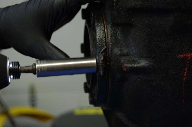
3 Step 6. Remove the output shafts. These should just pop out with a little tugging, but you may need to use a pry bar to get them out. They are splinned shafts and held in by a small circlip. 3

.")
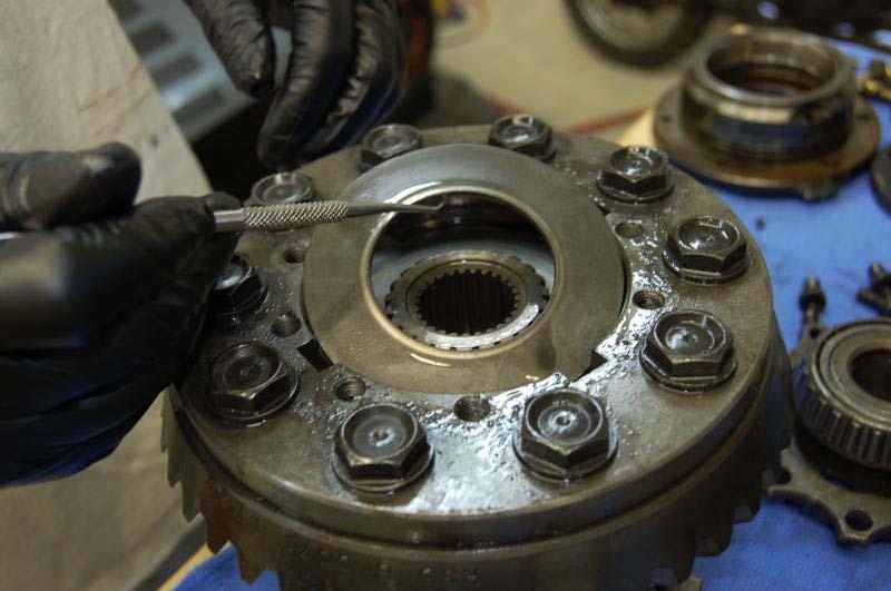
4 Step 7. Remove the outer bearing races/housings (13 mm hex head bolts). The differential housing should be lying horizontally, as it is when in the car, before you start this part of disassembly. You may have to give these a tap with a dead blow to get them loose and use a pry bar on the tab (facing up in installed position) to get them loose enough to remove. Keep track of the spacing disks since these determine bearing clearance (i.e., right and left may be different, so make sure you replace as removed). Carefully lower the internal assembly to the bottom of the case as these are removed to avoid damaging the ring gear and pinion. 4

5 5


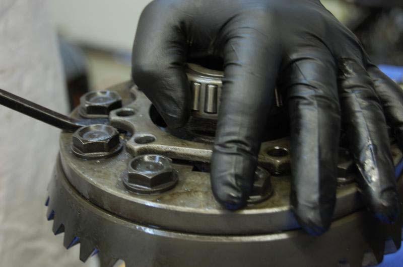
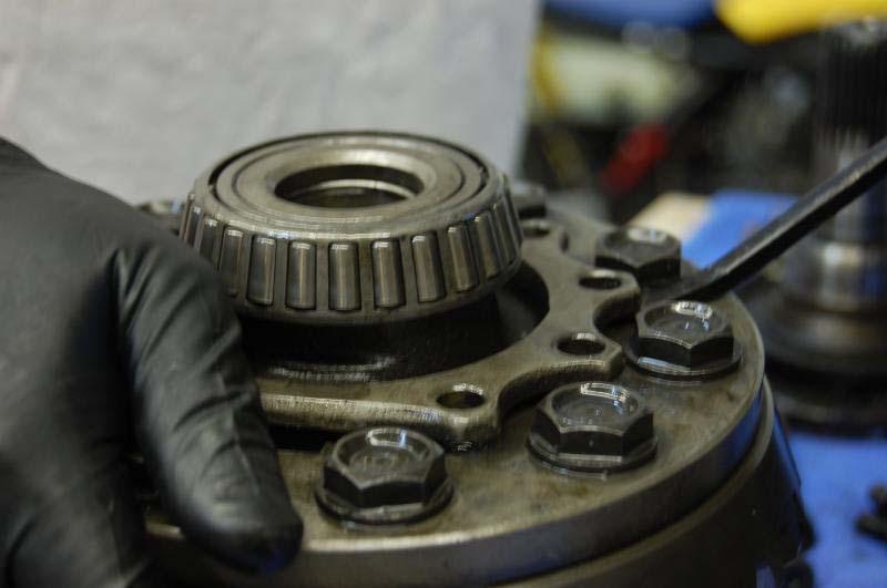
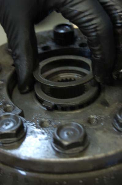
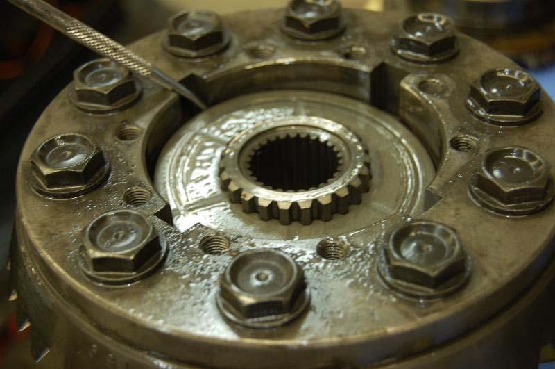
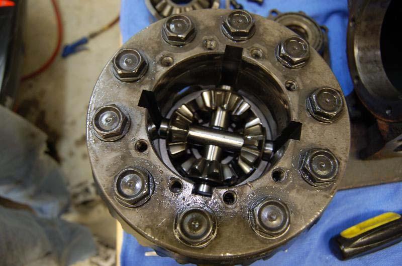
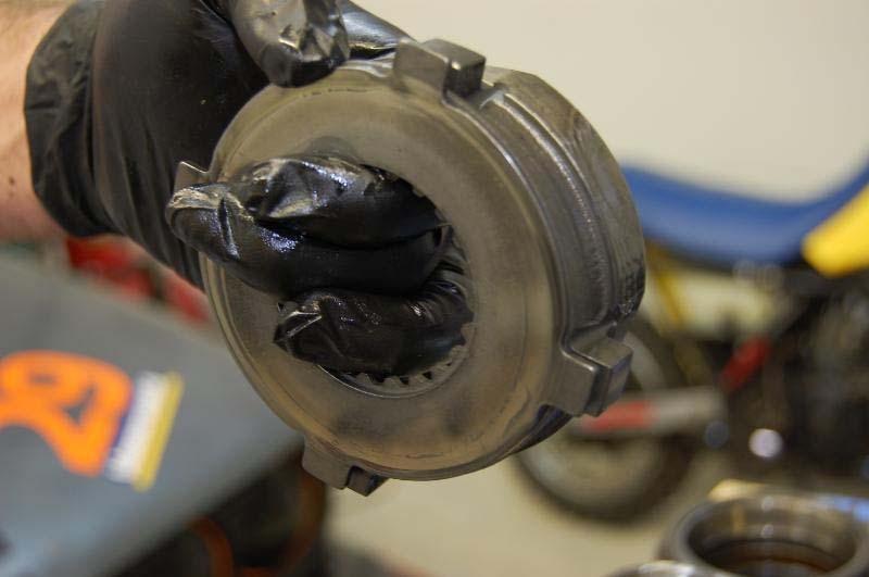
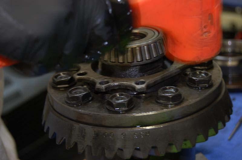
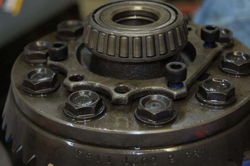
6 Step 8. Pull the limited slip assembly from the housing. Stand it on end so that the bearing with the cover plate side is facing up. Remove the 6 mm half-height socket head screws. Be careful as you may strip out the heads (as we did). 6

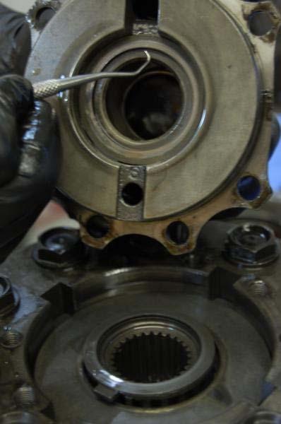
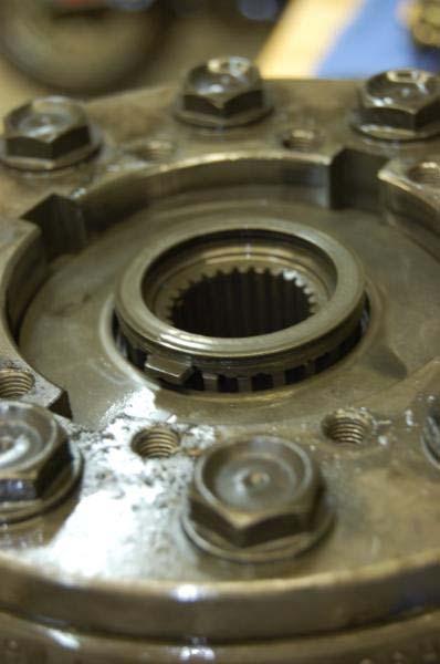
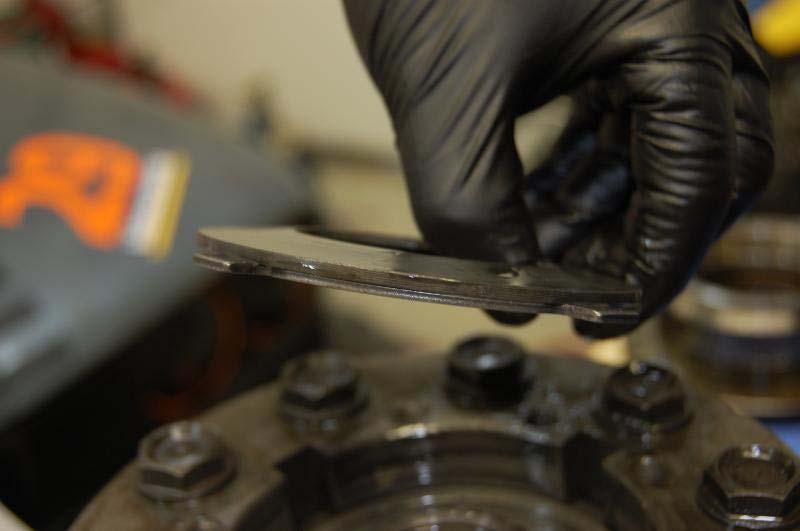
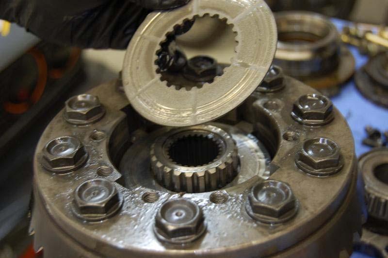
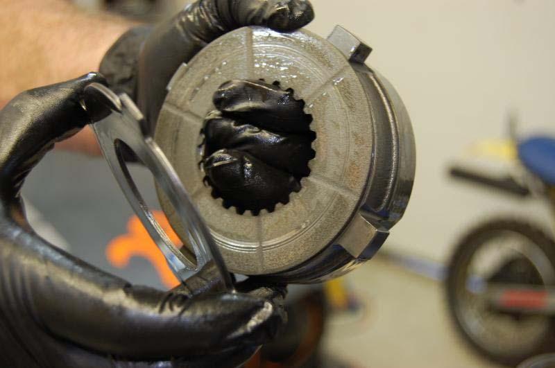
7 Step 9. Remove the cover plate. This may require to gentle prying with a pry bar or screw driver. Move around prying small amounts around the surface. This will require some patience. As the cover is released pay careful attention the washers underneath. These will need to be reinstalled in the same order. In addition, there is a larger convex washer. This will need to be reinstalled later in the same direction. 7
8 8


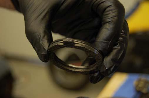
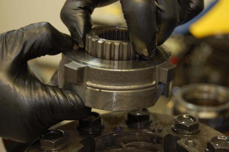
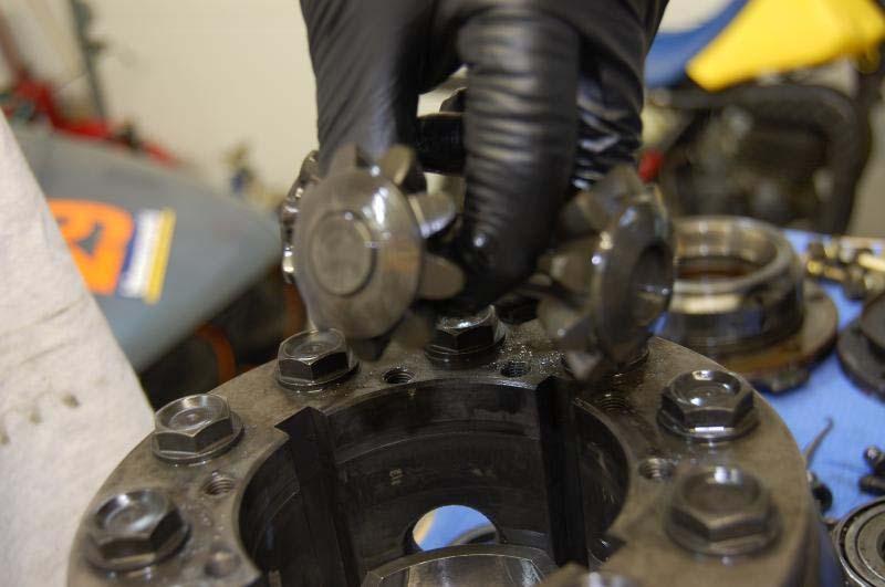
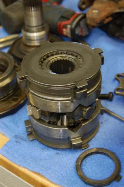
9 Step 10. Remove the internal parts friction surfaces, clutch discs, gear clusters. One of the clutch discs will be one side of the center gear cluster, the other one on the other side. As you remove the parts, it may be helpful to stack them as you remove them so you can reinstall in the same in order. 9
10 10
11 11
12 12
13 13
14 14

15 15
16 16

17 17


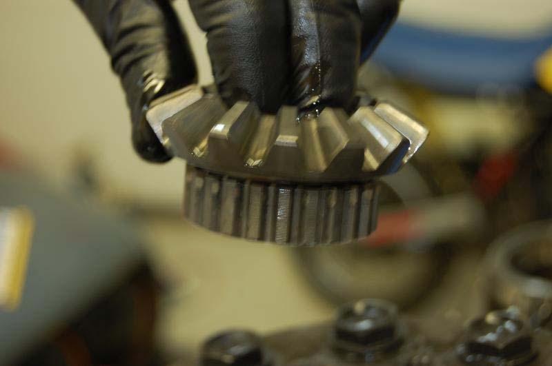
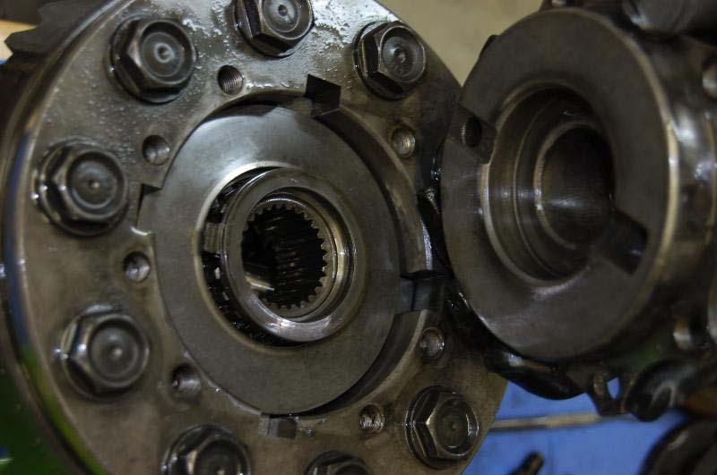
18 Step 11. Install clutch discs. Adjacent to each disc is a dog ring friction disc. These should be flipped to provide a fresh friction surface. 18


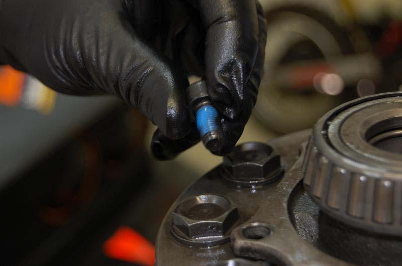
19 Step 12. Reinstall internal components by reversing order of removal. Replace cover. This will require some finesse to make sure everything is in alignment. Threading bolts in several holes make help with keeping appropriate alignment of the cover and the bolt holes. Torque the 6 mm socket head screws to 10 ft-lbs. Lock-tite is not required, but we used it. It may be helpful to use one of the output shafts to align the washers that go inside the cover. Note the location of the tab on the lower washer and the notch in the cover. 19
20 20
21 21

22 Step 13. Replace the internal assembly into the case. This can be done alone, however having a second person may help. You will need to hold the assembly and rotate in input shaft to mesh it with the ring gear. This will need to be done as the outer bearing race covers are placed back into the sides of the case. Replace the 13 mm hex head bolts and snug down. 22
23 Step 14. Replace the cover with 17 mm hex head bolts. RTV may help prevent leaks. Snug down and fill with gear oil. 23
Installation Instructions
 The IMS ETERNAL FIX PATENT PENDING Installation Instructions EPS recommends professional installation for the Eternal IMS Fix. Please take all precautionary safety measures. We also recommend putting the
RBP-1215B-RX DODGE RAM QUAD CAB RX3
 RBP-1215B-RX3 2002-2017 DODGE RAM 15-3500 QUAD CAB RX3 Passenger side RX-3 Side Step Drill Template Passenger side rear Modular Bracket (6) L Support Brackets Driver side rear Modular Bracket Driver side
BRAVO STERN DRIVE 3 C BRAVO ONE
 RAVO STERN DRIVE 3 C 22439 RAVO ONE Table of Contents Page Specifications............................... 3C-1 Torque Specifications..................... 3C-1 Preloads................................ 3C-1
DYNATRAC BALL JOINT REBUILD INSTRUCTIONS V4.0
 DYNATRAC PRODUCTS 2007-2016 4X4 JEEP JK HEAVY DUTY BALL JOINT JP44-2X3050-C DYNATRAC BALL JOINT REBUILD INSTRUCTIONS V4.0 WARNING: Improper use or installation of this product can cause major failures
PROSTEER BALL JOINT REBUILD INSTRUCTIONS V1.0
 DYNATRAC PRODUCTS 2003-2010 4X4 DODGE 2500/3500 HEAVY DUTY BALL JOINT PROSTEER BALL JOINT REBUILD INSTRUCTIONS V1.0 WARNING: Improper use or installation of this product can cause major failures that could
A-PDF Split DEMO : Purchase from to remove the watermark SHAFT DRIVE
 SHAFT DRIVE 4-1 A-PDF Split DEMO : Purchase from www.a-pdf.com to remove the watermark SHAFT DRIVE CONTENTS SECONDARY BEVEL GEARS... 4-2 CONSTRUCTION... 4-2 REMOVAL... 4-4 DISASSEMBLY... 4-4 INSPECTION...
GE-Westinghouse-AO Smith
 New products are developed and released throughout the year. Visit our website regularly pinsetterpartsplus.com GE-Westinghouse-AO Smith Combo Gearbox Conversion Kit Installation Guide New products are
DYNATRAC BALL JOINT REBUILD INSTRUCTIONS V5.0
 DYNATRAC PRODUCTS 2007-2018 JEEP JK HEAVY DUTY BALL JOINT JP44-2X3050-C DYNATRAC BALL JOINT REBUILD INSTRUCTIONS V5.0 WARNING: Improper use or installation of this product can cause major failures that
Astro-Physics Inc. 400QMD Lubrication/Maintenance Guide
 Astro-Physics Inc. 400QMD Lubrication/Maintenance Guide The following guidelines should be followed to lubricate the three main parts of the 400QMD mount. The QMD stands for Quartz Micro-Drive controller.
3.4 V6 MANUAL/AUTO or any 05- PRESENT 5-SPEED TRANSMISSION to cyl. 23 SPLINE GEAR DRIVEN T-CASE KIT INCLUDES: No. Part No. Qty. Ck.
 Page: 1 of 6 KIT INCLUDES: No. Part No. Qty. Ck. Box Description 1. 240-0020 1 Adapter Plate - Tacoma Transmission Adapter 2. 120-0020 1 Hardware Kit - Tacoma Transmission Adapter 3. 100-0001 8 Set Screw
HONDA RIDGELINE (KIT #601) Installation Instructions (to be used in addition to owners manual)
 Installation Instructions (to be used in addition to owners manual)") HONDA RIDGELINE (KIT #601) Installation Instructions (to be used in addition to owners manual) IMPORTANT NOTE: Read before beginning installation. These instructions replace all of Step 1 of the instructions
HONDA RIDGELINE (KIT #601) Installation Instructions (to be used in addition to owners manual) IMPORTANT NOTE: Read before beginning installation. These instructions replace all of Step 1 of the instructions
Click Here to Go Back
 Click Here to Go Back Fig. -94 Fig. -97 CC42D 10. Remove the cap screw securing the gear shift stopper plate pin retainer; then remove the retainer. Fig. -95 CC45D 12. Remove the link arm and account for
INSTALLATION INSTRUCTIONS DODGE RAM 2 & 4WD 1500 PART # P5058
 INSTALLATION INSTRUCTIONS 2009-13 DODGE RAM 2 & 4WD 1500 PART # P5058 PARTS LIST: Qty Description Qty Description 1 Grille Guard 12 12-1.75mm Hex Nuts 2 Upper Frame Mounting s (for trucks without tow hooks
INSTALLATION INSTRUCTIONS GRILLE GUARD RAM 1500 PART # 5058/5058-2
 INSTALLATION INSTRUCTIONS GRILLE GUARD PART # 5058/5058-2 PARTS LIST: Qty Description Qty Description 1 Grille Guard 8 12-1.75mm x 35mm Hex Bolts 2 Upper Frame Mounting s (for trucks without tow hooks
GE-Westinghouse-AO Smith Backend Gearbox Conversion Kit Installation Guide
 New products are developed and released throughout the year. Visit our website regularly pinsetterpartsplus.com GE-Westinghouse-AO Smith Backend Gearbox Conversion Kit Installation Guide New products are
TorqueMaster Replacement Spring
 TorqueMaster Replacement Spring Installation Instructions NOTE: Use these installation instructions in conjunction with the TorqueMaster Repair / Replacement Spring Program literature. Copyright 999 Wayne-Dalton
Bearing Overhaul Instructions for: Tallboy (.1) 2009
 2009") Bearing Overhaul Instructions for: Tallboy (.1) 2009 Tools Needed: 7900 Removal Tool 7902 Removal Tool 7900/7902/6902 Press Tool Grease Gun (included with frame) (2) ll/16" or adjustable wrenches 9/16"
Bearing Overhaul Instructions for: Tallboy (.1) 2009 Tools Needed: 7900 Removal Tool 7902 Removal Tool 7900/7902/6902 Press Tool Grease Gun (included with frame) (2) ll/16" or adjustable wrenches 9/16"
4/29/2016 Big Block Main Bearing Stud Girdle Kit HUG7380K For B & RB Blocks
 Big Block Main Bearing Stud Girdle Kit HUG7380K For B & RB Blocks Contents of Kit 2-4.40 Main Studs 8-5.187 Main Studs 1- Girdle Plate 18- ½ ARP black flat washers 8- ½-20 Grade 8 plain hex nuts 8- ½-20
To remove sanding pad, turn counterclockwise.
 Disassembly Instructions - Dynorbital EXTREME Models: All Important: Disconnect sander from the air supply. Notice: Use these instructions along with the tool manual. To avoid damage, use the special repair
INSTALLATION MANUAL FRONT. See pages 2 and 3 of this manual for configuration options. Level of Difficulty. Product Photo (center section only)
") INSTALLATION MANUAL FRONT Level of Difficulty Moderate Product Photo (center section only) All hardware listed below will be provided with the bumpers center section. Additional hardware will be supplied
INSTALLATION MANUAL FRONT Level of Difficulty Moderate Product Photo (center section only) All hardware listed below will be provided with the bumpers center section. Additional hardware will be supplied
4.2 - PUMP MAINTENANCE MODELS: AC, AS, WC, WS
 4.2 - PUMP MAINTENANCE MODELS: AC, AS, WC, WS 4.2.1 - EXPLODED VIEW DRAWING REF NO. 1 2 4 QTY 3 1 1.5 5 ¾ HP HP HP HP HP DESCRIPTION PART # 1 CASE 1.25 x 1 NPT 018266 1 CASE 1.25 X 1 NPT 018268 1 CASE
Installing the Partridge RA Extension on Losmandy G11
 Installing the Partridge RA Extension on Losmandy G11 Michael Herman July 20, 2015 Tools: 3/16 inch hex key (allen wrench) [If desired for DEC indicator ring friction improvement: flat screwdriver, and
It s a good idea to identify the Front and Rear cylinder heads. before starting the teardown process.
 It s a good idea to identify the Front and Rear cylinder heads using a paint pen before starting the teardown process. Use a 17/64 drill bit (or 6mm if you have metric drills or round stock) to lock the
INSTALLATION INSTRUCTIONS GRILLE GUARD 09-ON DODGE RAM PART #
 INSTALLATION INSTRUCTIONS GRILLE GUARD 09-ON DODGE RAM PART # PARTS LIST: Qty Description Qty Description 1 Grille Guard 8 12-1.75mm x 35mm Hex Bolts 2 Brackets (for trucks without 22 12mm x 30.1mm OD
Thank you for considering "cutting edge technology."
 Thank you for considering "cutting edge technology." Most woodworkers know that a shear cut is far better than a straight cut. They also know that a staggered cut is much better than just a single straight
IDR assembly instructions:
 IDR assembly instructions: Required Tools: 2 X 12mm Open End Wrench 14mm open end wrench #2 Phillips Head Screw Driver (Drill with adjustable torque clutch recommended) 8mm nut driver (Supplied in IDR-AK)
DRIVE COMPONENTS REMOVAL. 9. FXCW/C: see Figure Remove bolt (9), sprocket retainer (8), and thrust washer (7). NOTE PRIMARY DRIVE LOCKING TOOL
, sprocket retainer (8), and thrust washer (7). NOTE PRIMARY DRIVE LOCKING TOOL") DRIVE COMPONENTS REMOVAL PART NUMBER HD-7977 TOOL NAME PRIMARY DRIVE LOCKING TOOL S To remove the primary chain, remove compensating sprocket, clutch assembly and primary chain as an assembly:. Remove
DRIVE COMPONENTS REMOVAL PART NUMBER HD-7977 TOOL NAME PRIMARY DRIVE LOCKING TOOL S To remove the primary chain, remove compensating sprocket, clutch assembly and primary chain as an assembly:. Remove
Installation Instructions Precision Sport Shifter
 Installation Instructions Precision Sport Shifter 2004 and up Pontiac GTO Part Number 45043 2010, 2005, 2004 by B&M Racing and Performance Products This B&M Precision Sport Shifter has been designed to
REPAIR INSTRUCTIONS. Cat. No Cat. No MILWAUKEE ELECTRIC TOOL CORPORATION. SDS Max Demolition Hammer. SDS Max Rotary Hammer
 Cat. No. 9-0 SDS Max Demolition Hammer Cat. No. -0 SDS Max Rotary Hammer MILWAUKEE ELECTRIC TOOL CORPORATION W. LISBON ROAD BROOKFIELD, WISCONSIN 00-0 8-9-0 d 000 8-9-0 d Special Tools Require Forcing
Removing Right-Side. Components. Right-Side. Components. Click Here to Go Back AT THIS POINT
 Click Here to Go Back NOTE: There is an oil passage beneath the driven gear/drive gear assembly. This passage should be plugged prior to removing the driven gear and drive gear. Failure to do so could
RTI TECHNOLOGIES, INC.
 RTI TECHNOLOGIES, INC. BRC500 & BRC550 Arbor/Spindle Mechanism Adjustment & Service Technical Instructions The arbor/spindle mechanism of the BRC500/550 is designed to be robust for long life. Occasionally
ELECTRIC TOOL CORPORATION
 Cat. No. -0 / Hex Demolition Hammer Cat. No. 0-0 Spline Rotary Hammer MILWAUKEE ELECTRIC TOOL CORPORATION W. LISBON ROAD BROOKFIELD, WISCONSIN 00-0 -9-00 d 000 -9-00 d SpecialTools Require Forcing discs
Repacking the Spindle Bearings on a 1990 Enco RF-30 Mill/Drill, Version 1.1
 Repacking the Spindle Bearings on a 1990 Enco RF-30 Mill/Drill, Version 1.1 By R. G. Sparber Protected by Creative Commons. 1 Sorry about the rambling title but it was necessary. I looked at a few videos
Service Manual. 600 Series Box Frame Steering Shaft and Segment Gear Servicing
 Service Manual 600 Series Box Frame (These procedures are appropriate for box frame tractors produced after November 2002) IMPORTANT: READ SAFETY RULES AND INSTRUCTIONS CAREFULLY This Service Manual is
STOP. V00029AC Rev. 04 READ ALL OF THE FOLLOWING INSTRUCTIONS BEFORE REMOVING CABINET FROM SKID TOOL LIST. NET-ACCESS S-Type Network Cabinets
 Rev. 04 STOP READ ALL OF THE FOLLOWING INSTRUCTIONS BEFORE REMOVING CABINET FROM SKID NET-ACCESS S-Type Network Cabinets -Phillips screwdriver -Flatblade screwdriver -22mm socket wrench -15mm socket wrench
Installation Instructions
 Instructions Created by an: Suzuki Samurai, Sidekick, X90 Geo Tracker Off Road Universal Joint (SKU# SAX-UJOR) Instructions also apply to: SKU# SAX-UJOE, SDT-FY-9095, SAX-SY, STM-SL Installation Instructions
COYOTE ENTERPRISES, INC. RIMLOC BLAST WHEEL MAINTENANCE & ASSEMBLY MANUAL
 COYOTE ENTERPRISES, INC. RIMLOC BLAST WHEEL MAINTENANCE & ASSEMBLY MANUAL Parts & Machinery for the Abrasive Blast Industry 27301 East 121st Street Coweta, Oklahoma 74429 (918) 486-8411 Fax (918) 486-8412
MM Strut Tower Brace, GT (MMSTB-5.1)
") 3430 Sacramento Dr., Unit D San Luis Obispo, CA 93401 Telephone: 805/544-8748 Fax: 805/544-8645 www.maximummotorsports.com MM Strut Tower Brace, 1996-97 GT (MMSTB-5.1) MMSTB-5.1 is for 1996-97 GT s with
3430 Sacramento Dr., Unit D San Luis Obispo, CA 93401 Telephone: 805/544-8748 Fax: 805/544-8645 www.maximummotorsports.com MM Strut Tower Brace, 1996-97 GT (MMSTB-5.1) MMSTB-5.1 is for 1996-97 GT s with
SERIES I MILLING MACHINES
 INSTALLATION, OPERATION, MAINTENANCE, AND PARTS LIST SERIES I MILLING MACHINES TP5260 Revised: August 29, 2005 Manual No. M-450 Litho in U.S.A. Part No. M -0009500-0450 June, 2003 MAINTENANCE PROCEDURES
PEDESTAL OVERHAUL. Some of the tools for a pedestal overhaul. Pedestal work stand
 INTRODUCTION A properly greased labyrinth seal will help prevent dust and water damage to the pedestal bearing oil supply and shaft seal area. Properly greased and oiled pedestals rarely require an overhaul.
IMPORTANT: PLEASE RETAIN THIS INSTRUCTION MANUAL FOR FUTURE REFERENCE
 IMPORTANT: PLEASE RETAIN THIS INSTRUCTION MANUAL FOR FUTURE REFERENCE 005-07 Cadillac STS Classic 3D Z, Classic Dual Weave, Classic Mesh & Classic Black Mesh Grilles B 7 HR 3 STS Classic 3D Z Grille Part
B B B
 Stock with Scorpion Recoil Pad B..0.0 B..0.0 B..0.0 Removable/Adjustable Tactical Cheekrests X Scorpion Recoil Pad Dual Sided QD Attachment Point Six Position Adjustable Stock Slim Line Rear Aluminum Receiver
MODEL T " SPIRAL CUTTERHEAD INSTALLATION INSTRUCTIONS
 MODEL T27449 8" SPIRAL CUTTERHEAD INSTALLATION INSTRUCTIONS The Model T27449 indexable insert spiral cutterhead is designed to replace the straightknife cutterhead on the Grizzly jointer Model G0490W/G0490XW
Dairy Cap Chuck. Service & Installation Instructions. An Altra Industrial Motion Company P-2021-WE
 Dairy Cap Chuck P-2021-WE Service & Installation Instructions An Altra Industrial Motion Company Setting Application Torque 1. Determine initial clutch setting from torque chart below. Recommended Maintenance
Giraud Tool Company, Inc.
 Motor Upgrade for Gracey Trimmer This package is intended to allow the user to upgrade their Gracey trimmer with a higher rpm motor and convenience features not found in the production offering. This upgrade
Required Tools: Procedure:
 Depending on the materials you process through your chipper, their moisture content, the climate you live in, and many other factors you may have difficulty removing the rotor from the engine shaft. The
CAUTION! This manual contains important information for the correct installation, operation and maintenance of the equipment described herein.
 CAUTION! This manual contains important information for the correct installation, operation and maintenance of the equipment described herein. All persons involved in such installation, operation, and
MODEL H " BYRD SHELIX CUTTERHEAD INSTRUCTIONS
 MODEL H9291 12" BYRD SHELIX CUTTERHEAD INSTRUCTIONS The Model H9291 12" Byrd Shelix cutterhead is designed to replace the straight-knife cutterhead on the Grizzly jointer Model G0609. The total procedure
Jass.Performance Low Profiles Installation Manual
 Jass.Performance Low Profiles Installation Manual What is in the box: 2x Adapter Frame 2x Outer Panels 2x Inner Panels Pushrod, Ball Joints & Brackets 2x Hella Headlights 6x Springs 4x M6x25 Cross Head
Replacing the Starter Ring Gear on the Motorcycle Dyno
 Replacing the Starter Ring Gear on the Motorcycle Dyno Dynojet Research, Inc. 200 Arden Dr. Belgrade, MT 59714 Last Updated 10/12/1999 P/N 98221100 1 Starter Ring Gear Replacement This manual explains
INSTALLATION INSTRUCTIONS
 AUTOMOTIVE PRODUCTS, INSTALLATION INSTRUCTIONS PLATINUM 4 OVAL STEP BAR (90 BENT END) APPLICATION: 2010-2015 Dodge Ram 2500/3500 Mega Cab PART NUMBER: 21-3570, 21-3575, 23-3570, 23-3575, 25-3570, 25-3575,
INSTALLATION OF WELLS SUPER QUICK CHUCK LEFT HAND ON RED WING LATHE
 DENTAL, INC. TECHNICAL BULLETIN Q824-022510 5860 FLYNN CREEK ROAD READ ALL INSTRUCTIONS P.O. BOX 106 BEFORE PROCEEDING COMPTCHE, CALIFORNIA, U.S.A. 95427 SAVE THIS FOR FUTURE REFERENCE www.wellsdental.com
Installation Instructions
 Installation Instructions XLC Generation 2 Self-aligning split bearing Experience In Motion 1 Equipment Check 1.1 Follow plant safety regulations prior to equipment disassembly: Lock out motor. Wear designated
C70 Window Roller Repair Taken from: Heres the problem:
 C70 Window Roller Repair Taken from: http://www.volvospeed.com/vs_forum/topic/115086-how-to-c70-window-rollers-permanent-fix/ Heres the problem: This happened to two separate window assemblys on my c70
Inventory (Figure 2)
") MODEL T10130/T10126 6" & 8" SPIRAL CUTTERHEAD INSTRUCTIONS The Model T10126/T10130 indexable insert spiral cutterheads are designed to replace straightknife cutterheads from the Grizzly jointer Models
MODEL T10130/T10126 6" & 8" SPIRAL CUTTERHEAD INSTRUCTIONS The Model T10126/T10130 indexable insert spiral cutterheads are designed to replace straightknife cutterheads from the Grizzly jointer Models
C4 Fabrication Rock Slider Installation 14+ 5th Gen 4Runner w/o KDSS
 C4 Fabrication Rock Slider Installation 14+ 5th Gen 4Runner w/o KDSS Thank you for your purchase of the C4 Fabrication s 5th Gen 4Runner Rock Sliders! This product was carefully crafted to ensure a perfect
16 STEEL CABINET HEAVY DUTY
 HEAVY DUTY 16 STEEL CABINET ASSEMBLY INSTRUCTIONS SIX DRAWER BASE CABINET 12-2013 Parts List Part No Description Qty Image SIX DRAWER BASE CABINET Part No Description Qty Image SB-1 Cabinet Body 1 SLD-01
INSTRUCTIONS INSTRUCCIONES CONSIGNES
 AUTOMOTIVE PRODUCTS, INC. INSTRUCTIONS INSTRUCCIONES CONSIGNES APPLICATION: GMC SIERRA 1500 HDX & SPORTSMAN GRILLE GUARDS (2014 & UP) APPLICATION PART # S 57-3690, 57-3695, 40-3695, 45-3690 ITEM QUANTITY
Inventory (Figure 2)
") MODEL T10127 12" SPIRAL CUTTERHEAD INSTRUCTIONS The Model T10127 indexable insert spiral cutterhead is designed to replace the straightknife cutterhead from the Grizzly jointer Model G0609. The total procedure
MODEL T10127 12" SPIRAL CUTTERHEAD INSTRUCTIONS The Model T10127 indexable insert spiral cutterhead is designed to replace the straightknife cutterhead from the Grizzly jointer Model G0609. The total procedure
5X Racing Mazda Miata Shifter Rebuild Kit Installation Instructions
 5X Racing 1999-2005 Mazda Miata Shifter Rebuild Kit Installation Instructions Thank you for purchasing our Miata shifter rebuild kit for the 1999-2005 Mazda Miata! These instructions will guide you on
Install. Jeep JK Adventure Tire Carrier. Tools Needed. Hardware
 Jeep JK Adventure Tire Carrier Thank you for purchasing the Adventure upper tire carrier from JcrOffroad! Checkout our website, www.jcroffroad.com for more deals and other great off road products. Please
Assembly & Installation Instructions FOR VEHICLE MOUNT KIT USING VEHICLE CENTER MEMBER
 Assembly & Installation Instructions FOR VEHICLE MOUNT KIT 991002 USING VEHICLE CENTER MEMBER 9910092 TO FIT 99 - LATER Chevrolet 2500 Silverado 4x4 and 3500 Pickup 4x4 99 - LATER GM 2500 Sierra 4x4 and
Lumber Smith. Assembly Manual. If you are having problems assembling the saw and need assistance, please contact us at:
 Lumber Smith Assembly Manual If you are having problems assembling the saw and need assistance, please contact us at: 804-577-7398 info@lumbersmith.com 1 Step 1 Safety Carefully read the Owners Manual.
Parts Included: Tools Required: Canvas Office Landscape Interiors Off Module 90 Connector Kit Installation and Disassembly for Recycling Instructions
 Y Parts Included: Canvas Office Landscape Interiors Off Module 90 Connector Kit Installation and Disassembly for Recycling Instructions FT127.A N Shim A Light Seal B Foam Light Seal C G H Double-Face Tape
General Four-Way Operation, Maintenance & Service Manual
 General Four-Way Operation, Maintenance & Service Manual SCOPE Included in the following pages you will find assembly drawings, exploded views, parts lists, assembly tips, operational descriptions and
OPERATIONAL MANUAL V1.0. Removing/Replacing Blades
 OPERATIONAL MANUAL V1.0 BLUEROCK WS-212 Wire Stripper Removing/Replacing Blades CAUTION!! IMPORTANT!! DANGER!! WARNING!! DISCONNECT MACHINE FROM POWER BEFORE PROCEEDING!! Estimated Completion Time: 90
CTTR Tire Rack Required tools
 CTTR Tire Rack Required tools Torque wrench, ratchet, 9/16 socket, tape measure, and square edge. ASSEMBLY REQUIREMENTS *Torque all T-bolt nuts to 35-40 foot pounds. Failure to follow the assembly instructions
1 of 12 5/24/2015 9:43 AM
 1 of 12 5/24/2015 9:43 AM REAR PROPELLER SHAFT ASSEMBLY Components REMOVAL 1. REMOVE PROPELLER WITH CENTER BEARING SHAFT ASSEMBLY 2 of 12 5/24/2015 9:43 AM a. Place match marks on the propeller shaft flange
HDL(M)6 Nut/Screw Assembly
6 Nut/Screw Assembly") HDL(M)6 Nut/Screw Assembly Remove, repair, and reassemble the nut and screw assembly in your HDL series double lock vise. In these instructions when we refer to the front of the vise or nut/screw assembly,
HDL(M)6 Nut/Screw Assembly Remove, repair, and reassemble the nut and screw assembly in your HDL series double lock vise. In these instructions when we refer to the front of the vise or nut/screw assembly,
1. Turn off or disconnect power to unit (machine). 2. Push IN the release bar on the quick change base plate. Locking latch will pivot downward.
. 2. Push IN the release bar on the quick change base plate. Locking latch will pivot downward.") Figure 1 Miniature Quick Change Applicators, of the end feed type, are designed to crimp end feed strip terminals to prestripped wires. Each applicator is set up to accept the strip form of certain specific
Figure 1 Miniature Quick Change Applicators, of the end feed type, are designed to crimp end feed strip terminals to prestripped wires. Each applicator is set up to accept the strip form of certain specific
TECHNICAL INFORMATION
 TECHNICAL INFORMATION P 1 / 11 Model No. Description CONCEPT AND MAIN APPLICATIONS Specification Standard equipment TCT saw blade... 1 Rear table set (exclusively Europe, Turkey, South Africa..1 2704 This
DO35 MAINTENANCE INSTRUCTIONS
 CUSTOMER INFORMATION SHEET NO. 038 DO35 MAINTENANCE INSTRUCTIONS (DO35 V3 LAUNCHED PRODUCTION JUNE 2017) Table of Contents 1.0 Replacing Spindle Bushes V3... 22 2.0 Replacing Locking Mechanism V3... 6
Inventory (Figure 2)
") MODEL T24631 8" SPIRAL CUTTERHEAD Installation INSTRUCTIONS For questions or help with this product contact Tech Support at (570) 546-9663 or techsupport@grizzly.com Introduction The Model T24631 spiral
MODEL T24631 8" SPIRAL CUTTERHEAD Installation INSTRUCTIONS For questions or help with this product contact Tech Support at (570) 546-9663 or techsupport@grizzly.com Introduction The Model T24631 spiral
HEAVY DUTY 11 STEEL CABINET
 HEAVY DUTY STEEL CABINET ASSEMBLY INSTRUCTIONS ONE DRAWER BASE CABINET 05-206 Parts List Part No Description Qty Image ONE DRAWER BASE CABINET Part No Description Qty Image SB- Cabinet Body EH-0 Euro Hinge
OTECO INC. MODEL ,000 PSI 4-1/16 PORT DM GATE VALVE MAINTENANCE MANUAL
 Page 1 of 7 OTECO INC. MODEL 45 4 5,000 PSI 4-1/16 PORT DM GATE VALVE MAINTENANCE MANUAL Page 2 of 7 TABLE OF CONTENTS 1. Assembly Blowout 2. Repair Kit Contents & Technical Specifications 3. Disassembly
Installation Guide for Rough Country 1.25 inch Body Lift Kit w/o Shocks (07-15 Wrangler JK 4 Door) Item # J10048 Option B; Manual
 Item # J10048 Option B; Manual") Installation Guide for Rough Country 1.25 inch Body Lift Kit w/o Shocks (07-15 Wrangler JK 4 Door) Item # J10048 Option B; Manual Installation Time: 3 Hours Tools Required: Jack (Tall enough to reach body
Installation Guide for Rough Country 1.25 inch Body Lift Kit w/o Shocks (07-15 Wrangler JK 4 Door) Item # J10048 Option B; Manual Installation Time: 3 Hours Tools Required: Jack (Tall enough to reach body
DOOR KIT P/N APPLICATION BEFORE YOU BEGIN KIT CONTENTS. Instr Rev Page 1 of 6. Verify accessory fitment at Polaris.com.
 DOOR KIT P/N 2882528 APPLICATION Verify accessory fitment at Polaris.com. BEFORE YOU BEGIN Read these instructions and check to be sure all parts and tools are accounted for. Please retain these installation
Brother Industries, Ltd. Nagoya, Japan
 4. 2001. This service manual has been compiled for explaining repair procedures of the MODEL XL-6562, XL6452, XR- 46. This was produced based on up-to-date product specifications at the time of issue,
INSTALLATION OF WELLS SUPER QUICK CHUCK LEFT HAND ON BALDOR LATHE
 DENTAL, INC. TECHNICAL BULLETIN Q832-022510 5860 FLYNN CREEK ROAD READ ALL INSTRUCTIONS P.O. BOX 106 BEFORE PROCEEDING COMPTCHE, CALIFORNIA, U.S.A. 95427 SAVE THIS FOR FUTURE REFERENCE THIS PRODUCT IS
Maintenance Information
 47104302 Edition 1 November 2012 Cordless Drill/Driver QX Series Maintenance Information Save These Instructions Tool Diagnosis 1. Before servicing this unit, you will need a fully charged battery of known
INSPECTION AND CORRECTION OF BELLHOUSING TO CRANKSHAFT ALIGNMENT
 INSPECTION AND CORRECTION OF BELLHOUSING TO CRANKSHAFT ALIGNMENT BACKGROUND Proper alignment of the transmission input shaft to the crankshaft centerline is required in order to achieve the best results
Lab Style Table Frame Part No Assembly Guide Automation Technology
 Ergonomic Workstations Lab Style Table Frame Part No. 8 0 Assembly Guide 7 90 70 Automation Technology SPECIFICATIONS Lab style frame part number... 80 Height... 70 mm (8.") Width... 90 mm (.7") Depth...
Engineering Data Single Reduction Parts List Item # Description Basic Single Reduction Unit 1. Gear Housing 2. Pipe Plug 3. Vent Plug 4. Splash Guard
 Engineering Data Single Reduction Parts List Item # Description Basic Single Reduction Unit 1. Gear Housing 2. Pipe Plug 3. Vent Plug 4. Splash Guard 5. Input Cover 6. O-Ring 7. Hex Head Cap Screw 8. Input
Mechanical Frappe Press
 Mechanical Frappe Press Operation Manual CONTENTS OPERATIONAL INSTRUCTIONS PRECAUTIONS PART NAMES INCLUDED ITEMS BASIC OPERATION MAINTENANCE REPLACEMENT PARTS Thank you for using The Frapptastic Five Mechanical
RC4WD R2 Disconnect Transmission parts replacement guide
 RC4WD R2 Disconnect Transmission parts replacement guide Version 1.1 Thank you for your purchase. Welcome to the RC4WD family. This transmission is a combination of many specially engineered and manufactured
PPM-5710 JK HEAVY DUTY SKID PLATE ASSEMBLY Version 2.0
 SYNERGY MFG. 870 INDUSTRIAL WAY, SAN LUIS OBISPO, CA (805) 242-0397 PPM-5710 JK HEAVY DUTY SKID PLATE ASSEMBLY Version 2.0 GENERAL NOTES: These instructions are also available on our website; www.synergymfg.com.
FRONT BUMPER INSTALLATION INSTRUCTIONS Toyota 4Runner
 Aluminess Products Inc 9402 Wheatlands Ct. #A Santee, CA 92071 619-449-9930 FRONT BUMPER INSTALLATION INSTRUCTIONS 2003-2009 Toyota 4Runner Please read before beginning Stainless steel hardware may bind
AT ADAPTER INSTALLATION INSTRUCTIONS
 IMPORTANT: THIS IS A HIGH PERFORMANCE PART AND IMPROPER INSTALLATION COULD RESULT IN INJURY OR DEATH! NEVER WORK UNDER AN AUTOMOBILE THAT IS NOT PROPERLY SUPPORTED AND BLOCKED FROM ROLLING. NO CREDIT OR
INSTALLATION GUIDE Rear Bumper. Jeep JL Wrangler
 INSTALLATION GUIDE Rear Bumper Jeep JL Wrangler Dual Swing System 1A From the stock bumper you removed from vehicle, you ll need to take the parking sensor wiring from it and feed it into the new bumper.
PRS Retro Z-Axis Installation
 PRS Retro Z-Axis Installation Page -1- PRS Retro Z-Axis Installation This document is a guide to installing the PRS Retro Z-axis on early ShopBot models. It describes installation for PR models with PK299
3. Remove the flue collar by backing out the two Phillips round head machine screws.
 SERVICE MANUAL SERVICE PROCEDURES Defiant Non-Catalytic Model 1610 Woodstove **Wear gloves, a dust mask and protective eyewear when servicing a stove. ** Replacing the Fountain Assembly 1. Remove the doors,
Jenny Legs Assembly Instructions
 Jenny Legs Assembly Instructions R EXTENDED PHILLIPS BIT MM ALLEN WRENCH 6MM HEX DRIVE /" 007 Steelcase Inc. Grand Rapids, MI 90 U.S.A. Printed in U.S.A. Page of 6 88000 Rev F Jenny Club Instructions:
Eraser Conveyor Belt Cleaning System IWARNING Always obey all applicable safety rules. Be sure all power to the conveyor has been disconnected and con
 INSTALLATION GUIDE LIB-CP-REA-03-01 Rev. 10 Eraser Conveyor Belt Cleaning System ARGONICS Eraser Conveyor Belt Cleaning System IWARNING Always obey all applicable safety rules. Be sure all power to the
Maintenance Information
 16601023 Edition 2 January 2014 Air Impact Wrench 2705P1 Maintenance Information Save These Instructions Product Safety Information WARNING Failure to observe the following warnings, and to avoid these
SIGNATURE FRONT BUMPER INSTALL
 SIGNATURE FRONT BUMPER INSTALL JL **PLEASE READ THROUGH THE INSTRUCTIONS BEFORE BEGINNING ANY PART OF THE INSTALLATION PROCESS** 1. You can now remove the trim strip (2 vertical clips, 4 horizontal, 2
Mounting Instructions For 3-Piece Namur Style Mounting Bracket To 2-Way 60 Series Valves
 Mounting Instructions For 3-Piece Namur Style Mounting Bracket To 2-Way 60 Series Valves NOTE: These instructions apply only to 60 series ball valves with bodies containing external mounting nibs. External
RC4WD Diablo V2 Instruction Manual
 Version 1.1 RC4WD Diablo V2 Instruction Manual Thank you for your purchase. Welcome to the RC4WD family. This kit is a combination of many specially engineered and manufactured parts. Enjoy your build.
INSTRUCTIONS 360 CHAINROLL
 INSTRUCTIONS 360 CHAINROLL 360 CHAINROLL REGISTRATION Please visit productregistration.360yieldcenter.com to complete the product registration for your 360 CHAINROLL so we can better support our products
MM Strut Tower Brace, Cobra (MMSTB-7)
") The MM strut Tower Brace attaches to each strut tower and to the firewall. 3430 Sacramento Dr., Unit D San Luis Obispo, CA 93401 Telephone: 805/544-8748 Fax: 805/544-8645 www.maximummotorsports.com MM
The MM strut Tower Brace attaches to each strut tower and to the firewall. 3430 Sacramento Dr., Unit D San Luis Obispo, CA 93401 Telephone: 805/544-8748 Fax: 805/544-8645 www.maximummotorsports.com MM
Midwest RDH Handpiece Repair Procedure
 Midwest RDH Handpiece Repair Procedure The Midwest RDH handpiece is fairly common and is used by hygienists to clean teeth. The most common problems for this handpiece include a bad prophy head or a dirty