THE POWER OF RED STEEL-PLY CONCRETE FORMING SYSTEM APPLICATION GUIDE
|
|
|
- Nelson Manning
- 6 years ago
- Views:
Transcription


1 THE POWER OF RED STEEL-PLY CONCRETE FORMING SYSTEM APPLICATION GUIDE
2
3 Table of Contents Introduction...1 Handles...1 Components...1 Safety Eyes...1 Fillers... 2 Wedge Bolts... 2 Steel Fillers and Long Bolts... 3 Adjustable Long Bolts... 3 Job Built Fillers... 4 Stripping and Tie Breakbacks... 4 Ties... 5 Tie Capacities... 5 Tie Alignment... 5 Tie Spacings... 5 Special Purpose Ties and Hardware... 6 Single End Threaded Ties... 6 Adjustable Single End Threaded Ties... 6 Ties Threaded Both Ends... 6 Single End Threaded Toggle Ties... 7 #1 Cone Ties... 7 #2 Cone Ties... 7 #2A Cone Ties... 8 S-Pilaster Ties... 8 Base Tie Bolts... 8 S-Base Ties... 9 Pre-Bent Ties... 9 Accessories... 9 Pipe Walers " Aligner Channels / 3" Channel Aligner Brackets...10 Pilaster Forms and Short Bolts...10 Pilaster Braces Pilasters formed with Inside Corners Bay Corners...12 Bay Corner Brackets...12 Hinged Corners...13 Culvert Forms...13 Form Aligners...14 Turnbuckle Aligners...15 Pipe Form Aligners...15 Scaffold Brackets...16 Brick Ledge Brackets...16 Beam Pockets...16 Form Extension Brackets...17 Cantilever Brackets...17 Haunch Support Brackets...18 Handset Erection Procedures Sill Plates...20 Footing Forming with Steel-Ply Panels...20 Erection Procedures...22 Sloped Footings...24 Stepping Forms...24 Bulkheads Wall Corners Intersecting Walls Walers Strongbacks Stacking Forms Second Lift Forming...30 Adjustable Shear Wall Brackets...31 Anchor Inserts...31 Anchor Bolts...31 Guide Bolts...31 Multi-Shear Wall Brackets Conventional Panel Tie Gang Forming...33 Assembling Gangs Gang Form Ties Cone Ties Form Alignment Tie Removal Curved Walls Curved Gang Forming Horizontal Gang Alignment " Aligner Channel / 3" Channel Aligner Bracket Vertical Strongbacks Steel Ply Gang Fillers Sizes...40 Double Duty Lift Brackets...40 Waler...41 Turnbuckle...41 Double Duty Lift Bracket...41 Scaffold Bracket...41 Ties...42 Horizontal Steel-Ply Horizontal Gang Assembly Walers...44 Waler Splice Channels Y Walls with 45 Walers and Splices Maxi-Waler Wall Gangs Assembly Spreader Clip...50 Adjustable Top Tie...50 Waler Lift Brackets...51 Ganged Core Forms Double Hinged Fillers Lifting Core Forms Double Hinged Filler Double Hinged Filler Columns Column Wedge Bolt Positions Adjustable Column Form Extender Column Filler Angle Ganged Columns Quick Column Hardware...60 Column Lift Corner (CLC)...60 Column Form...60 Adjustable Rectangular Column Form...61 Battered Walls Batter Tie Down Bracket Index /16 THE POWER OF RED SYMONS
4 2 THE POWER OF RED 05/16
5 INTRODUCTION The Steel-Ply components and accessories illustrated herein have been designed with safety and performance in mind to help achieve a safe and productive forming operation. It s recommended that all construction personnel thoroughly familiarize themselves and comply with the applicable industry standards and safe practices established by the American Concrete Institute (ACI), American National Standards Institute (ANSI), The Occupational Safety and Health Administration (OSHA), and the Scaffolding, Shoring and Forming Institute (SSFI). Tie spacings shown are for illustration purposes only. Proper spacing must be determined for individual job conditions. Refer to Ties section for tie capacities. The maximum allowable pour pressure for the Steel-Ply system is 1000 psf. Handles Steel Ply standard handles are designed to be used to assist in manually transporting or positioning each modular panel, and should not be used as a means of attachment or for any other purpose. COMPONENTS Safety Eyes The installation of Safety Eyes on Steel-Ply panels allows easy attachment of safety belts while working on the forms, though work platforms are recommended and normally provide more efficient working conditions. The Safety Eye meets the requirements of OSHA (29 CFR Part 1926) subpart M d15. Safety Eye Installation SAFETY EYE 16D NAIL WEDGE BOLT WITH 16D NAIL SECURES SAFETY EYE WEDGE BOLTS Safety Eye Installation CAUTION: DO NOT use handles as a safety belt hookup or as a connecting point for bracing, scaffolding or ganged movement of panels. CAUTION: Do not use Safety Eye as a Lifting Bracket. Do not attach to a single horizontal side rail. 5' Steel Ply Panel 05/16 THE POWER OF RED CAUTION: Symons recommends gloves, safety shoes and safety glasses during the panel erection and stripping processes SYMONS
6 Fillers Steel-Ply Fillers are manufactured from the same steel and plywood as panels, and are available in all even inch widths from 4" to 22" and 5". These fillers require wall tie connections to both side rails, and therefore either the same size filler must be in position directly opposite or some specific form detail that will accept the wall tie connections. Wedge Bolts Two identical Wedge Bolts function as a lock-bolt set, one as a connecting bolt, the other as a clamping wedge. At typical side rail to side rail form connections, the loop end of the tie is positioned in dado slots and is secured by the same Wedge Bolts. For typical walls, form connecting Wedge Bolts are only required at standard tie connection positions. Additional Wedge Bolts are utilized at other positions for attachment of walers, scaffold brackets or other accessory components. PANEL TIE OR FLAT TIE Typical Steel Ply Filler Application Filler width may be determined by looking carefully at the end rails. Slots are located in 6" increments from each end of the end rail for fillers from 10" to 22". NOTES: Front and rear dadoes align on 12" centers. Three foot high forms have front and rear dadoes at 6" centers. Handles are added to 20", 22" and 24" wide frames. 5', 6' and 8' length frames have two handles. 3' and 4' lengths have one handle. There are no Wedge Bolt slots or dadoes on 4", 5", 6" and 8" filler end rails. All other end rails have slots and dadoes at 6" O.C. from both ends. Typical Wedge Bolt Connection through Ties and Side Rails A sufficiently tight Wedge Bolt connection can be achieved by pushing down on the head of the vertical Wedge Bolt with one hand while striking the head of the lateral Wedge Bolt with a hammer. The vertical Wedge Bolt will respond downward to a tight, secure position. Excessively tightened Wedge Bolts require excessive labor during stripping. Care should be taken when striking Wedge Bolts with a hammer during assembly and disassembly. PUSH DOWN Slot Spacing for Filler End Rails Hammer Strikes Horizontal Wedge Bolt 2 THE POWER OF RED 05/16
7 Steel Fillers and Long Bolts 1", 1½" and 2" Steel Fillers are cold formed U-shaped steel. These fillers utilize a Long Bolt that passes through the filler to grip both adjoining side rails. Tie slots are located in the center of the face of the U for wall ties. The Long Bolts pass through the loop end of the ties. The Long Bolt is punched with two ¼" holes to accommodate a 16D, or 20D nail, or a broken off panel tie end to shorten the bolt for 1", and 1½" steel fillers. See the Adjustable Long Bolt section. Adjustable Long Bolt Short Stop Hole No. ADJUSTMENT RANGE Width of Filler Wedge Bolt at Square End Width of Filler Wedge Bolt at Tapered End 1 0" 2" to 2¼" 2 ¼" to ½" 1½" to 1¾" 3 ¾" to 1" 1" to 1¼" 4 1¼" to 1½" ½" to ¾" 5 1¾" to 2" 0" to ¼" Typical Steel Filler Application CAUTION: If tension exists in job-built filler, tension rods must be installed through panel siderails. If compression exists, lumber blocking is required. Adjustable Long Bolts We recommend that the tapered end of all of the Adjustable Long Bolts at each fill-in joint be pointed in the same left or right direction. The width of the filler determines if the Wedge Bolt is located in the slotted hole at the square end or the slotted hole at the tapered end. Application: 1. For width of fillers from ½" to 2" in ½" increments insert Wedge Bolt in slotted hole at tapered end. 2. For width of fillers from ¼" to 1¾" in ½" increments insert Wedge Bolts in slotted hole at square end. NOTES: Form Ties must be used at all filler conditions. Do not short stop with nail where there will be a high shear load on nail. Typical Examples of Adjustable Long Bolt and Steel Filler Applications 05/16 THE POWER OF RED SYMONS
8 Job Built Fillers (Utilizing Filler Angles) Filler Angles provide a means to construct a custom size filler of ¾" plywood that can be connected to side rails of adjoining forms. Job-built fillers are recommended where reinforcing steel, pipes, etc., must protrude through the form face. Stripping and Tie Breakbacks Panel stripping can be started at any point after walers and connecting hardware are removed. Usually, it is easier to start stripping forms at an outside corner, or adjacent to a 1", 1½" or 2" filler. It is recommended that hardware be placed in a metal container so that none of the pieces are lost. CAUTION: Symons recommends wearing gloves, safety shoes and safety glasses during the erection and stripping processes. Breakback of ties is recommended within two days after stripping. With S-Panel ties, a ½ to ¾ twist will break them back. Typical Filler Angle Attachment Typical Job-Built Filler with Filler Angles Breaking Back a Wire Tie Flat ties are broken off by a firm hammer blow hitting the edge of the tie as shown. A blow against the flat side of the tie will bend the tie. Typical Job-Built Filler with Rebar Penetrations Breaking Back a Flat Tie Custom Inside Corner Job-Built With Two Filler Angles CAUTION: Care should be used in striking ties with a hammer during the stripping process. 4 THE POWER OF RED 05/16
9 TIES Tie Spacings Tie Capacities Safe Load Ratings Symons S-Panel and Flat Ties Ultimate Load (lb) Rating According to Factor of Safety 2.0 (lb) Standard Duty Panel Tie 4,500 2,250 Standard Duty Threaded Tie (1) 4,200 2,100 Standard Duty S-Base Tie 3,000 1,500 Heavy Duty Panel Tie 6,000 3,000 Standard Duty Flat Tie 6,000 3,000 Heavy Duty Flat Tie 7,000 3,500 Heavy Duty Adjustable Flat Tie 7,000 3,500 Toggle Tie (1) 4,200 2,100 (1) Tie capacity is dependent on adequate anchorage Tie Alignment Occasionally, to simplify erection, it may be advantageous to connect ties between opposing form joints that are not exactly opposite. Either panel ties or flat ties can be safely swung laterally up to 1" on 8" walls, or up to 2" on 16" walls. Exceeding the 1:8 angle proportion will diminish the tie strength or cause failure by bending through the tie breakback crimp. Also, the wall thickness dimension will foreshorten appreciably. Tie Spacings Walls 8' Tall or Less Lateral Swing of Panel Tie Panel ties can swing up or down up to 1" on 8" walls, or up 2" on 16" walls. An example would be where a plate is utilized under one form side only. A ¾" thick 1 x 4 plate under one side for any wall thickness 6" or more, or a 1½" thick 2 x 4 plate under one side for any wall 12" or thicker are within the 1:8 angle proportion. NOTE: Ties at 1' O.C. 7' or more from top. Tie Spacings Walls Taller Than 8' 6,000 lb Ultimate Tie Capacity Vertical Swing of Panel Tie Vertical Swing of Flat Tie REV. 05/1610/16 THE POWER PERFORM OF WITH RED PRECISION SYMONS
10 SPECIAL PURPOSE TIES AND HARDWARE The ultimate load capacity of threaded ties is 4,200 lbs which provides for a safe load of 2,100 lbs at 2:1 safety factor. There are three types of threaded ties. Single End Threaded Ties A typical application provides the varying fractional inch wall tie requirement common to most battered walls. Threaded ties have a special ¼" x 20 thread and require use of a special ¼" x 20 threaded nut. Spreader action is provided through utilization of the Keeper Bolt. The Keeper Bolt takes the place of a standard Wedge Bolt at each threaded tie panel connection. The tie contains a breakback flat at the threaded end, and a breakback tool must be used to twist the tie end. The ease or effectiveness in performing the tie breakback will depend upon how deep the breakback flat is embedded in the concrete. Breakback depths up to 1" should readily twist off. Adjustable Single End Threaded Ties This tie has approximately 5" of length adjustment available but does not have a breakback flat at the threaded end. It should only be used in applications where a minimum below surface breakback is not required; such as, the back fill side of a battered retaining wall. Adjustable Single End Threaded Tie Ties Threaded Both Ends Thread at both ends offers twice the range to adjust to job variations in wall thickness and still retain reasonable assurance toward breaking back the tie utilizing the jaw grip breakback tool. Single End Threaded Toggle Ties Tie Threaded Both Ends THREADED TIE NOTES: Threaded Tie Connection to Steel-Ply Safe recommended load on the special ¼" x 20 tie thread is 2,100 2:1 safety factor. Standard thread length provides 2" of adjustment. The capacity of the toggle ties is dependent on adequacy of anchorage of toggle. Recommended vertical spacing for any type threaded tie 1'-0" O.C. for all wall heights. Single End Threaded Tie Extreme care should be taken to assure each nut is adjusted so that each tie will carry its share of form load. Use the Keeper Bolt. 6 THE POWER OF RED 05/16
11 The toggle end threaded tie facilitates two basic application connections: #1 Cone Ties #1 Cone Ties and Z-Tie Holders are used for job-built forms comprised of ¾" plywood, 2x4 studs and double walers. Ties must be placed before second adjoining form is erected. In most cases, outside walls are erected first, ties are secured, and then the inside wall is erected, guiding on the protruding ties. Single End Threaded Toggle Tie 1. Toggle ties provide for field weld attachment to steel piling, structural steel, etc. #1 Cone Tie Single End Threaded Toggle Application #1 2. Toggle ties provide anchorage to lumber or steel sheathing by inserting the toggle through a 7 8" diameter hole in the sheathing and securing its bearing position with an activating wire. #2 Cone Ties #2 Cone Ties and Z-Tie Holders facilitate tieing vertical panels opposite job-built forms comprised of ¾" plywood, 2x4 studs and double 2x4 walers. Normally, it is advantageous to erect the job-built side first with ties and bracing installed. The Steel- Ply panels on the opposite side would be automatically aligned parallel to the previously waled job-built forms. Single End Threaded Toggle Application #2 #2 Cone Tie 05/16 THE POWER OF RED SYMONS
12 #2A Cone Ties #2A Cone Ties and Z-Tie Holders will connect vertical panels opposite job-built forms comprised of ¾" plywood and double 2x4 walers directly against the plywood (no studs). Tie loops are perpendicular to each other. Base Tie Bolts The Base Tie Bolt will secure either a panel tie or a flat tie to an end rail or a side rail resting on a footing or where panels butt against an existing vertical surface. One end of the tie must be connected to the first form side prior to its placement. The tie is then in position to receive the opposite form side. The Base Tie Bolt first pass through the ties and then through the panel connecting slots. The connection is secured by a 16d nail inserted through a nail hole in the nose of the Base Tie Bolt. #2A Cone Tie S-Pilaster Ties The overall length of a pilaster tie positions opposite wall panels at a given wall thickness. The breakback flat at one end is moved inboard to establish a breakback point on the tie ahead of a brick ledge or other type boxout. S-Pilaster Tie Double pilaster ties have special breakbacks positioned from both ends of the tie. Base Tie Bolt Application S-Double Pilaster Tie 8 THE POWER OF RED 05/16
13 S-Base Ties The S-Base Tie has an up-turned open loop at each end which protrudes up through the bottom rail connecting bolts slots. Wedge Bolts insert through the protruding loop ends. Pre-Bent Ties ACCESSORIES Pipe Walers The Pipe Aligner Hook will secure 1½" (schedule 40) pipe or 1.90" O.D. tubing for use as walers. The aligner hooks position in the dado slots between side rails at either 6" or 18" from the top and/ or bottom end rails and two Wedge Bolts make the connection. S-Base Tie (No Breakback Standard) (Many types available) Unusual wall shapes on occasion warrant the need for special factory pre-bent ties. The form joint points of connection for pre-bent ties are predetermined and located on the engineering layout furnished. Pre-Bent Tie CAUTION: Do not attempt to bend ties on the job. Bent tie capacity is less than straight ties. The greater the bend, the less the capacity. Consult a qualified Symons representative for capacities. Pipe Aligner Hook Installation Attachment procedure requires that the pipe waler length be held in position prior to inserting the aligner hooks into the form joint dado slots. The first (lateral) Wedge Bolt is tapped through the connection with a hammer. A snug tightening action results due to the slight under tolerance length of the aligner hook. A second locking Wedge Bolt secures the connection. Pipe walers should not be utilized as load gathering walers as the Pipe Aligner Hook is not designed to support concrete pressure loads and the pipe may crush or bend. Two pipes can be lapped and clamped at the same Wedge Bolt connection by utilizing two Pipe Aligner Hooks. The first Pipe Aligner Hook is attached with two Wedge Bolts (normal fashion). The second Pipe Aligner Hook holds the other pipe and is attached to the protruding end of the lateral connecting Wedge Bolt. A double head nail may be inserted in the Wedge Bolt s nail hole as a keeper. Alignment continuity can be accomplished by lapping pipes over two or more panel joints and utilizing two or more double hook positions. Installation of Two Pipe Aligner Hooks 05/16 THE POWER OF RED SYMONS


14 3" Aligner Channels / 3" Channel Aligner Brackets Single 3" Aligner Channels provide excellent straight wall alignment when they are attached with 3" Channel Aligner Brackets and 8" Gang Waler Rods. Curved walls can be aligned with 3" Aligner Channels that have been custom rolled to the required curvature. Pilaster Forms and Short Bolts The Pilaster Form is adjustable in 1" increments for pilasters from 1" to 12" deep. There are two connecting flanges, one for even-inch increments, such as 2", 4", 6" and the other for the odd increments such as 1", 3", 5", etc. 3" Channel Aligner Bracket Slot Spacing on Pilaster Form To determine which end of the flange is even, and which end odd, simply measure the space between the first increment slot and the edge of the form. On one end, the measurement is 2" from the edge, and on the other end, it is 3" from the edge. Typical Application Aligner Channel on Top or Bottom If, for example, odd increments are desired, the 2" side of the flange is placed nearest the wall. For even increments, flip the Pilaster Form over, placing the 3" end nearest the wall. Channels can be lapped and clamped at the same Wedge Bolt connection by utilizing a Gang Waler Plate. In order to lap past each other, the 3" Aligner Brackets must be installed with one 3" channel above the Gang Waler Rods and the other channel below the waler rods. Lapping channels and clamping with Gang Waler Plates at two or more panel joints, provides alignment continuity of one length to the other. Lapping channels also saves cutting longer lengths to fit a shorter dimension. Typical Pilaster Form Application A Short Bolt eliminates the need for short-stopping or shimming Wedge Bolts, and makes stripping easier when properly installed. Lapping Channels Short Bolt 10 THE POWER OF RED 05/16

15 Where the Pilaster Form joins the panel at the wall and Short Bolts are not available, short-stopping is necessary. Insert a nail in the horizontally placed Wedge Bolt s nail hole, thus drawing up the wedge so that insertion of the vertically placed Wedge Bolt forms a snug connection. On the opposite, or outside end, where the pilaster is attached to the filler, loose fitting Wedge Bolts can be tightened by shortstopping or shimming. To shim, slip an extra Wedge Bolt horizontally on the connecting Wedge Bolt, insert through pilaster and filler, and lock in place with a third Wedge Bolt (see illustration). The Pilaster Brace is needed on only one side of the pilaster. Two braces are required on the bottom form and one brace on each additional stacked form. The first brace should be located 6" or 18" from the bottom of the pour. Additional braces should be located 6" or 18" below the end rail of each form. Avoid interference with walers or ties. A panel must be located next to the pilaster form to facilitate brace connection. Attach Pilaster Braces with Steel-Ply Wedge Bolts at the panels and a Short Bolt at the Pilaster Form Pilasters formed with Inside Corners Pilasters are also formed using Inside and Outside Corners with appropriately sized fillers. Short Bolt Short-Stopping and Shimming Each Pilaster Form displaces 3" of wall face dimension adjacent to the wall tie at its flange-to-panel connection, therefore the form opposite the pilaster must be 6" wider than the pilaster being formed. Pilaster Braces The Pilaster Brace eliminates the need to use lumber for bracing the corners of Pilaster Forms in order to achieve right angle corners on pilasters. STEEL-PLY PANEL PILASTER FORM Typical Panel, Filler and Panel Tie Configuration for Pilasters NOTE: Flat Ties cannot be crossed as shown in diagram above. SHORT BOLT AND WEDGE BOLT WEDGE BOLTS PILASTER BRACE Typical Pilaster Brace Installation 05/16 THE POWER OF RED SYMONS

16 Bay Corners Inside Bay Corners opposite Outside Bay Corners form a 135 angle wall corner. The Inside Bay Corner has a 3"x3" face dimension, and the Outside Bay Corner has a 7"x7" face dimension. Panel ties connect at adjoining panel joints the same way as they do on standard 90 corners. Bay Corners can be used horizontally to form wall haunches and sewage treatment plant Y Walls. Bay Corner Brackets Bay Corner Brackets and two appropriately sized fillers can be used in place of Outside Bay Corners. The brackets should be placed at crossmember locations, starting 1'-0" from the bottom. Do not attach bracket to Steel Fillers. Outside Bay Corner Inside Bay Corner Typical Bay Corner Bracket Installation Typical Y Wall Typical Bay Corner Application Steel fillers or job-built fillers enable Bay Corners to adjust to any wall thickness. WALL THICK- NESS FILLER SIZE REQUIRED WALL THICK- NESS FILLER A SIZE REQUIRED WALL THICK- NESS FILLER B SIZE REQUIRED 6" 1½" 6" 5½" 6" 8½" 8" 5 8" 8" " 8" " 10" 1 8" 10" 7 1 8" 10" " Bay Corners and Fillers 12" 1" 12" 8" 12" 11" 12 THE POWER OF RED 05/16
17 Hinged Corners The Inside Hinged Corner may be used to form inside corners down to 45. The Outside Hinged Corner will form outside corners from 135 down to as sharp as a 5 angle. Always insert connecting Wedge Bolts toward the adjoining panels so that the maximum swing angle will not be restricted Culvert Forms The Culvert Form creates the chamfered corners that prevail in box culverts. On most chamfer cornered culverts, the roof slab and walls are poured monolithically. Panel ties are usually required at the horizontal form joint between the Culvert Form and the top rail of the inside forms. This means the outside form must also have a horizontal joint at the same elevation, so that tie dadoes occur at the same staggered positions at opposing form sides. A top tie is then required over the deck to the outside form on the other wall side of the culvert. The deck forms must be properly shored to support the dead and live concrete placement loads. Culvert Form Angle Typical Culvert Form Application Inside Hinged Corner Outside Hinged Corner In most wall applications, Inside Hinged Corners are used opposite Outside Hinged Corners. Outside and Inside Hinged Corners CAUTION: Due to the inherent flexibility of hinges, corners formed should be waled, braced and blocked as required. CAUTION: Do not use Hinged Corners in column applications. Use Column Hinges shown in Quick Column Hardware section. Culvert Form Dimensions 05/16 THE POWER OF RED SYMONS


18 Form Aligners Form Aligners are required to position forms straight and plumb and are not intended to resist concrete pressure or any other loads. Symons attachment plates secured to lumber provide a very quick and sturdy alignment connection directly to any panel joint. NAILS 2" X 4" The ground end of the aligner can be nailed to either a Symons steel stake or a lumber stake. TURNBUCKLE ALIGNER 6" ADJUSTMENT STEEL STAKE Typical Turnbuckle Aligner Application Typical Form Aligner Attachment to Steel Ply CAUTION: Wall and column forms must be adequately braced to safely support all foreseeable lateral loads associated with wind, eccentric loading, etc. The materials, quantities, locations and methods of attachment and anchorage of the bracing design shall be the responsibility of the contractor based on job site conditions and applicable industry standards. Form Alignment for Stacked Forms PIPE FORM ALIGNER ADAPTER 1 8" X 4½" COUPLING PIN AND HAIRPIN CLIP PIPE FORM ALIGNER EXTENSION PIPE FORM ALIGNER TURNBUCKLE Forms Alignment with Walers and Braces PIPE FORM ALIGNER SHOE Typical Pipe Form Aligner Application 14 THE POWER OF RED 05/16

19 Turnbuckle Aligners An additional adjustment advantage may be gained by utilizing a Symons Turnbuckle Aligner nailed to the end of a lumber brace. The lower end of an Turnbuckle Aligner contains a large rectangular slot to accommodate a Symons steel stake. It can also be nailed to a lumber stake. If the strongbacks are lumber, a wood aligner can be nailed on; or if Symons steel Versiform walers are utilized as strongbacks, the attachment plate end of the adjustable turnbuckle can be bolted to the strongback with a standard 5 8" x 6" Versiform Fit-Up Bolt. Pipe Form Aligners The Symons Pipe Form Aligner is adjustable from 11'-7" up to 20'-9" and connects to side rails by utilizing the Steel-Ply Pipe Form Aligner adapter at the Wedge Bolt slot midway between crossmembers. A Pipe Form Aligner Adapter is not required to connect directly to vertical Versiform waler strongbacks. Either end of the aligner may be installed between the double 5" waler channel with a 5 8" x 6" Fit-Up Bolt. A Pipe Form Aligner Shoe is utilized at the ground end of the Pipe Form Aligner. It has openings for anchoring with a ¾" dia. concrete anchor bolt or a Symons flat or ¾" dia. round steel stake which may be driven into the ground. Attachment to Versiform Waler CONNECTION TO EXTENSION TUBE Pipe Form Aligner CONNECTION TO TURNBUCKLE TUBES Pipe Form Aligner Attachment to Strongbacks CONNECTION TO EXTENSION TUBE CONNECTION TO TURNBUCKLE TUBES SHOE CONCRETE ANCHOR BOLT SYMONS STEEL STAKE SHOE Pipe Form Aligner Attachment to Steel Ply 05/16 THE POWER OF RED Anchoring Methods for Pipe Form Aligner SYMONS
20 Scaffold Brackets Scaffold Brackets should be installed where one or more levels of work platforms are required for personnel safety whenever access to forming components or concrete placement necessitates work above grade or deck levels. The allowable load on a Scaffold Bracket is 500 lbs, and brackets shall not be spaced more than 8 feet apart in accordance with applicable OSHA standards, and shall be in compliance with all applicable governmental regulations, codes and ordinances. Brick Ledge Brackets The Brick Ledge Bracket is designed for quick attachment of brick ledges and various other types of box-outs such as beam pockets and window openings that extend to the top of a wall. Connection to panels is made with Wedge Bolts. The nailer plate end of the Brick Ledge Bracket is 3 3 8" long and requires the 2x4 to be the minimum width framing member. In most applications, nailing through the backside of the Steel-Ply panel plywood is required to hold the bottom of the box-out tight against the form face. Scaffold Bracket Attachment Use a Wedge Bolt through the bracket slot and the panel side rails. Lock the Wedge Bolt with the S-Wedge cabled to the bracket. Be sure the clevis on the lower end straddles the side rails. Typical Brick Ledge Bracket Installation Beam Pockets The Beam Pocket is nailed to the Steel-Ply form to provide a ledge in the finished concrete for an 8" deep steel beam to set on. Typical Beam Pocket Installation CAUTION: Do not attempt to secure Scaffold Bracket to ties after forms are removed or in any manner other than as illustrated. Beam Pocket and Concrete Void 16 THE POWER OF RED 05/16
21 Form Extension Brackets The Form Extension Brackets are a convenient means for extending a standard panel wall height, an additional 3" to 12" on straight or curved walls. The brackets are designed to be used with ¾" plywood or sheathing boards and are very practical for saving the most expensive panel plywood at the top of a wall that requires rebar protrusions through the form face. The brackets are 12" in length and have slots at either end for connecting to panels. They also have center slots so that a waler can be attached. The brackets attach with a Wedge Bolt up from the top rail of the panel below and may be locked rigid with an S-Wedge. The S-Wedge is necessary to bridge between the opposite side slots of the bracket while drawing the connecting Wedge Bolt tight. Cantilever Brackets Cantilever Brackets suspend an opposing form from the first wall side erected. This makes possible the difference in elevation at the bottom of the forms so that a base slab can be monolithically poured with the wall. The capacity is 700 lbs and maximum spacing is not to exceed panel length when forms are hung horizontally or 8'-0" when hung vertically. When the suspended forms are horizontal, a Long Bolt with an S-Wedge connects the Cantilever Bracket to the form side rail. Typical Configuration Horizontal Suspended Forms When the suspended forms are vertical, a Cantilever Clip with Fast-Pin couples the Cantilever Bracket to the inside forms at the first connecting bolt slot (6" from the top rail). Typical Form Extension Bracket Installation Typical Configuration Vertical Suspended Forms CAUTION: Forms must be tied or braced as required. 05/16 THE POWER OF RED SYMONS
22 Haunch Support Brackets The Haunch Support Bracket is connected to the Steel Ply side rail using the attachment bolt on the cable and secured with a Wedge Bolt vertically. Then erect posts and stringers. Stringers should be securely attached to the Angle Support Plate as shown below. Formwork, stringers and posts must be in place and braced prior to placing any formwork or planking on Haunch Support Brackets. Haunch Support Bracket Haunch Support Bracket Hole Configuration Typical Haunch Support Bracket Application CAUTION: Grade must be sufficiently compacted to withstand all imposed loads without settlement. IMPORTANT: Above Caution must appear on layout drawing 18 THE POWER OF RED 05/16
23 05/16 THE POWER OF RED SYMONS
24 Footing Forming with Steel-Ply Panels Footing, pad and slab forming with Steel-Ply is made easy with the Footing Corner Bracket and the Stake Plate. Two Footing Corner Brackets at each corner, one on top and one on the bottom, hold the panels firmly and at virtually any dimension that your job requires (2" increments). The Stake Plates are then positioned along the top edge of the Steel Ply panels as needed for steel stakes to hold the forms in place against the concrete pressure. Either ¾" round or I beam steel stakes can be used with the Stake Plate. The Stake Plates can be located midway between Steel Ply crossmembers and end rails to provide access for a stake puller. HANDSET ERECTION PROCEDURES Sill Plates Panels can be set directly on the concrete footing working to a chalk line or on lumber plates. Plates are recommended because they provide a positive on-line wall pattern and level out rough areas on the footing. Plates function to preform the position and size of pilasters, changes in wall thickness, locate corners, etc. Typical Plate Configurations Typical Footing Corner Configuration Plates extend a level on-line surface for setting grade beam walls which only bear on intermittently spaced footing pads. All components assemble with standard Wedge Bolts. The Stake Plate is also designed to accommodate wood forms. It has two nail holes for this purpose. Stake Plate Typical Plate and Footing Pad Configuration Typical Stake Plate Application 20 THE POWER OF RED 05/16
25 Depending upon the distance between footing pads, it may be necessary to use stakes to align and level the plates. The Wedge Bolt, side rail tie connection is designed with easy-fit tolerances for speed of assembly. These tolerances permit up to ¼" of slack in a tie spreader action control of wall thickness. Any slack present between opposing forms is removed by lateral pressure during concrete placement. For this reason, panels should be nailed down, aligned and braced on one side of the wall only. The opposing forms are then free to pull out any tie slack without affecting alignment. Method 1 Stake and Plate Alignment/Leveling Method 2 Panels should be nailed down so that they will stay on line. (The panel face should be flush with inside edge of plate.) All panel and end rails contain 2 wide-spaced nail holes. The first panel is nailed at both nail holes. Subsequent panels require only one nail through the leading nail hole relative to panel setting direction. Panels Nailed to Plate A double thickness plate can be utilized to gain a small amount of extra form height, as an example, an 8' panel setting on a double plate will form an 8'-3" wall. This method is much easier than attempting to nail wood on top of the form. Panels Nailed to Plate Typical Double-Thickness Plate 05/16 THE POWER OF RED SYMONS
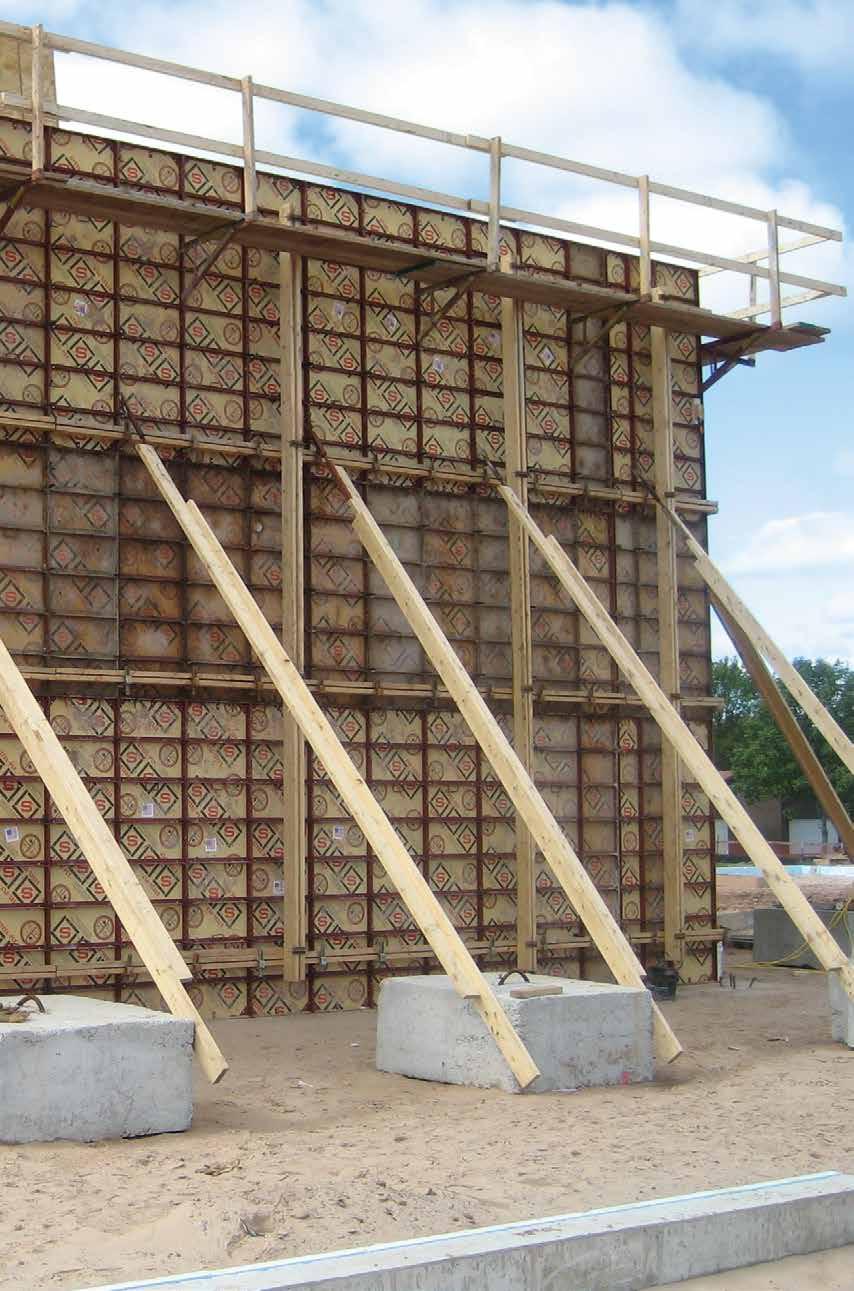
26 Erection Procedures There are several panel erection sequence variations. While some applications offer a choice, the job application often dictates the best method to be used. In practically all instances, it is recommended to start at a dimensionally positioned detail such as a wall corner or pilaster. This will ensure that not more than one filler will be required for any straight wall run. Step #1 Position connecting Wedge Bolts with approximately half of their shaft length projecting through the side rail slots at the prescribed tie positions (both opposing panels). Step #1 Step #2 Place ties over ends of projecting Wedge Bolts. Typical Start Point for Panel Erection For light construction foundations where reinforcing steel is not involved, ties can be installed along with both form sides in a single, coordinated sequence. If a wall corner can be selected as a starting point, erection procedure is as follows: First, connect an Outside Corner Angle to the two proper width adjacent fillers and set the inside corner in place. The width of the outside corner fillers is predicated by the wall thickness plus the face dimensions of the inside corner. For example, the outside corner fillers for a 10" wall utilizing a 6" x 6" inside corner would be 16" wide. This procedure lines up opposing form panel joints for tie placement. After two or three inside and outside panels along with ties are installed in each direction, the whole assembly should be plumbed and braced. A leveling shim should be used if needed. The progressing work cycle for installing each pair of opposite panels along with accompanying ties is illustrated in these five steps: Step #2 Step #3 One at a time, position the next pair of opposing panels in line with the tips of the protruding Wedge Bolts and immediately follow up with Step #4 and #5. Step #3 Step #4 Shove remaining length of connecting Wedge Bolts into the adjoining side rail slots. Step # THE POWER OF RED 05/16
27 Step #5 Move newly positioned panel to close gap between side rails (gap left at Step #4). Insert Wedge Bolts and tighten to a closed joint position. They should not be hammered down excessively. Step #5 Walers should be installed as soon as enough panels are erected to cover the waler lengths to be used. Likewise, alignment bracing should be installed immediately following the installation of each length of waler. Nailing the bottom panel rail on the alignment form side also takes place immediately after Step #5. Carpenter crews very quickly get the feel for erecting panels and will soon innovate procedure variations that work best for them. Foundation walls for heavier commercial and industrial construction usually require that one form side of a wall be erected first. Some of the reasons for this procedure are: rebar placement and tie-off alignment to form face, brick ledge and other boxouts to be framed in the wall. Normally, the first wall side set will incorporate all necessary aligning walers, strongbacks and form aligners for final wall alignment. Ties can be installed either with the first form side set or when the opposing panels are set. CAUTION: When ties are installed with the first form side, their protruding length is vulnerable to accidental bending damage. Replace any ties that are bent through their breakback flat or breakback notches. Typical Alignment Brace Installation 05/16 THE POWER OF RED SYMONS
28 Sloped Footings When footings are slightly sloped and particularly where the top of wall elevation is also sloped, it can be advantageous to erect panels perpendicular to the angle of slope. Where the sloped form must connect to plumb forms, the transition can be accomplished by building a wedge-shaped filler utilizing filler angles and the appropriately cut ¾" plywood. Stepping Forms Form Wedge Bolt connections match 6" or 12" increment steps that occur in footings. 12" increments can include properly installed panel ties due to adjoining tie dadoes. When 6" increments steps occur, side rail dadoes do not join, hence, if a tight form joint is required, flat ties can be installed in the half tie slot clearance of one side rail dado. Panel ties can be used at a single dado slot as long as tight form joints are not critical. The 2" steel fillers and 4" step fillers have connecting bolt slots every 2", and can be used to step forms in any 2" increment. For other than 6" or 12" increments, it is necessary to use separate Wedge Bolts to connect either form side of the filler. Typical Sloped Transition to Plumb Forms Most often, panels are erected level to the direction of slope. A wedge-shaped, job-built filler under the forms keeps the form joints vertical and the side rail slots and dadoes lined up. If the fill-in wedge tapers to exceed a 12" build-up, panels should step down at 12" side rail increments. Typical Step Forming with Panel Ties or Flat Ties The job-built, fill-in wedge must be properly braced at 12" side rail increments to minimize the height size of wedge-shaped filler to withstand the concrete pressure. Depending upon specific conditions, the anticipated pressure may warrant waling with additional ties through the wedge-shaped, job-built form. Typical Step Forming with Flat Ties Typical Sloped Filler Under Plumb Forms 24 THE POWER OF RED 05/16

29 Bulkheads Since Steel-Ply panels have plywood faces, bulkheads can be installed using the same methods utilized for securing bulkheads in conventional wood forms. Additionally, bulkheads can be formed using outside corners and wall thickness size filler or panel. Stepping Steel Ply in 6" or 12" Increments Lumber Bulkhead Filler Bulkhead Keyway Bulkhead Stepping Steel Ply in 2', 4", 8", or 10" Increments Forms can be stepped to any odd increment utilizing Filler Angles. Wall Corners Locking Wedge Bolts are required only at same elevations as wall tie placement. Connections must be through side rail slots adjacent to crossmembers. To avoid position conflict, the lateral Wedge Bolts should insert first through the Outside Corner Angle, so that the tightening Wedge Bolts will bear at the side rail side of each connection. Wedge Bolts should insert from the corner side into the panel. Typical Wedge Bolt Connection at Outside Corner Stepping Steel-Ply in Odd Increments 05/16 THE POWER OF RED SYMONS
30 Intersecting Walls When the thickness of an intersecting wall is 12" or less, a single panel or filler will span the dimension opposite the wall intersection permitting wall tie placement at both Inside Corner form joints. An intersecting wall thicker than 16" can be formed either by utilizing special pre-bent panel ties, or utilizing walers plus bracing to support the form joint where ties are not installed. The pre-bent special tie method is the recommended way, due to the fact that holding form loads via internal ties is more dependable than the unpredictable compression capacity of external bracing. Also, the load gathered by the waler may overload the adjacent ties. Typical Form and Tie Configuration for Intersecting Walls 12" Thick or Less If the intersecting wall is 13" to 16" thick, one or two steel fillers may be utilized at either side or both sides of a 2' panel to make up the necessary fill-in form dimension. As indicated in the sketch, the ties are canted at a slight angle due to their connecting through the tie slots centered in the face of the steel filler. Pre-Bent Panel Tie Application for Intersecting Walls over 16" Application Using Walers and Braces for Intersecting Walls over 16" CAUTION: Adjacent filler widths should be reduced accordingly to prevent overloading tie. Typical Form and Tie Configuration for Intesecting Walls 13" to 16" Specific job conditions can obstruct forms on one form side of a wall, such as large diameter sewer pipe that must be poured flush to the opposite form face. When forms are without opposing tie joints, the floating panel joints must be waled and properly braced. Typical Waler and Brace Configuration for Joint without Tie 26 THE POWER OF RED 05/16
31 Walers When setting panels utilizing either panel ties or flat ties, walers normally function in a form aligning capacity only. This is in contrast with many job-built lumber methods in which the walers are the main load gathering members to which the wall ties are secured. With the Steel-Ply forming system, the panel ties or flat ties connect directly to the panel side rails and their length terminate at that point. In effect, at each vertical row of ties, the adjoining side rails function as vertical steel walers; hence, the horizontal add on waler functions as an aligner only. For walls up to 8' high utilizing one panel lift and with a setting plate secured to the footing only one aligning waler either 6" or 18" from the top on the alignment side of the wall is required. The opposite form side gains alignment through the appropriate length wall ties. Z-Tie Holder Installation The One-Piece Waler Clamp offers the one-piece, hook-on advantage at any available adjoining side rail connection slot, that is not reserved for a panel tie connection, plus the unique advantage of functioning with two 2x4s or a single 2x4. Both 2x4s go over the top of the clamp and are wedged tight to the side rail. Typical Waler, Brace and Tie Positions for 8' Forms The Waler Tie and Z-Tie Holder are available in two lengths to secure either double 2x4 or double 2x6 lumber walers. This method offers the flexibility of placement by inserting the Waler Tie in side rail dado slots for connection with Wedge Bolts, or it can be positioned at a tie Wedge Bolt connecting point between the outside of a side rail and the Wedge Bolt. One-Piece Waler Clamp Installation 05/16 THE POWER OF RED SYMONS
32 Strongbacks Strongbacks are vertical alignment members that are placed at 90 to walers. The strongbacks are used to align the walers and are commonly placed at 8' O.C.; actual placement spacing is determined by specific job conditions. Materials for making up strongbacks can be doubled 2x4s, 2x6s or 2x8s, depending on stiffness required to satisfy specific applications. Typical Strongback Installation with Strongback Tie and Z-Tie Holder Typical Strongback Application Strongbacks are attached using either Strongback Ties with Z-Tie Holders or J-Strongback Hooks. Strongback ties secure at a side rail s Wedge Bolt connection, while the J-Strongback Hook simply hooks over one member of the lumber waler. When Strongback Ties are used in conjunction with lumber walers and strongbacks, the Strongback Tie can eliminate the need for a Waler Tie at that point. Typical Strongback Connection to Waler with J-Strongback Hook 28 THE POWER OF RED 05/16
33 Strongback ties have loops in the same plane as compared to Waler Ties which have loops perpendicular to each other. Typical Strongback Installation with U-Bolt and Pipe Waler Strongbacks for pipe waled forms are attached with a strongback U-Bolt. Either double 2x4 or double 2x6 lumber can be used. Stacking Forms Normally, panels should be stacked on top of panels and fillers over corresponding filler widths. For best panel face alignment, place hardware in first and third wedge slots on each panel end rail. Placement of hardware in the middle dado slot occurs when a tie is required. For a more positive connection, always install vertical Wedge Bolts point down with the locking Wedge Bolt at the underside. End Rail Dado Slots for Wedge Bolts Typical Wedge Bolt Locations for Stacked Forms It usually is best to start erecting stacked panels at a corner. On the first panel from the corner, install hardware in the first and third end rail Wedge Bolt slots. From that panel, most applications will require only one Wedge Bolt connection on the top panel to the one below it. That one connection should always be through the third end rail slot as measured from the last panel set. Panels at both form sides of a wall should be the same size so that their horizontal stacking joints are opposite each other. This facilitates placement of wall ties at the stacking panel joint when required, and assures that required vertical joint tie locations are available at both wall sides. Wall heights made up of two or more panels stacked bottom rail to top rail require waler alignment as close as possible to the stacking panel joints. 6" down from the top rail of each lower tier panel is the most practical position. That position permits the waler to be in place for preliminary alignment, and bracing prior to placement of the next tier of panels. When the top tier and bottom tier forms are either 6' or 8' panels, the top of wall and bottom of wall walers may be positioned either 6" or 18" from the corresponding end rails depending 05/16 THE POWER OF RED SYMONS
34 on preference location for scaffold brackets or other accessory hardware. When convenient, the top waler should be located as close as possible to the top of concrete pour. Alignment walers are only required at one side of the wall. Second Lift Forming There are several methods to support forms in a handset operation on top of a previous wall pour. One method is to utilize concrete embedded anchors which were secured to the prior pour formwork. After removal of the first lift forms, a timber is bolted to the anchors. This provides a ledge which will support the next lift of formwork. If the ledge is located an inch or two below the previous pour, good alignment between the subsequent pours can be achieved. Typical Strongback and Waler Configuration for Stacked Forms Horizontal panels may be stacked on top of vertical panels. In most applications, the same length horizontal panels should be installed at opposite form sides of a wall. The horizontal panels should be selective lengths so that vertical form joints occur where required for hardware and tie connection to vertically stacked fillers, pilaster forms, corners or any other detail that warrants a common vertical form joint. Second Lift with Supporting Lumber Another method is to leave the top tier of the previous forms in place undisturbed. The second lift of forms is then erected and supported as a continuation of the first lift forms. Typical Application Horizontal Panels Stacked on Vertical Panels Second Lift with Form Support 30 THE POWER OF RED 05/16
35 Adjustable Shear Wall Brackets We highly recommend the use of Symons Adjustable Shear Wall Brackets for vertical support of ganged forms. The bracket is attached with an insert that does not require drilling a hole through plywood. The threaded adapter plug is nailed to the plywood face and the insert is screwed on to the plug. After concrete is placed, and the form stripped, the plug is unscrewed. A fully threaded high strength ¾" bolt attaches the Adjustable Shear Wall Bracket to the insert. This bracket has a vertical adjustment range of over 2". The Adjustable Shear Wall Bracket Safe Working Load rating when mounted flush to surface in 3500 psi concrete is 3000 lbs at a 3:1 Safety Factor. NOTE: On applications using form liner, consult the Symons Branch Engineering Department for proper use of the Adjustable Shear Wall Bracket. Anchor Insert Installation CAUTIONS: 1. Remove forms before removing brackets 2. Do not attach bracket to irregular surface such as concrete formed with textured form liners. 3. Do not use Taper Ties or She-Bolts as gang supports. Anchor Inserts Dayton expanded coil insert, galvanized F-57, ¾ 10 UNC ferrule, 4 5 8" long. Attach insert to form face utilizing the Setting Plug (Dayton threaded plastic plug F-74 with ¾" 10 UNC threads. Anchor Bolts ¾" 10 UNC x 1½" long zinc-plated, Grade 5 bolt with full length threads. Guide Bolts The Guide Bolt is a separate item, and must be ordered when using the Adjustable Shear Wall Bracket with Steel Ply forms. Guide Bolts convert Adjustable Shear Wall Brackets into special function brackets for support of Steel Ply gangs. The bracket head plate has a 5 16" x ¾" slot for attaching the Guide Bolt. The shape of the Guide Bolt is symmetrical, so any way it is mounted, a 45 slope helps gravitate the gang into aligned position with the previous pour. Adjustable Shear Wall Bracket Installation The Adjustable Shear Wall Bracket elevation adjustment range is 2 3 8", or from 3½" to 5 7 8" at Dimension A. Dimension B usually includes a desired amount of previous pour overlap, but never less than the minimum 3½" dimension at A. For handset applications, do not use the Guide Bolt. Secure appropriately sized lumber to the top plate of the Adjustable Shearwall Bracket and set and secure forms on the lumber. 05/16 THE POWER OF RED SYMONS
36 Multi-Shear Wall Brackets The Multi-Shear Wall Bracket is used for support of wall gangs. The Multi-Shear Wall Bracket is adjustable from 3½" to 5 7 8", with a total vertical adjustment of 2 3 8". Safe Working Load Rating when mounted flush in 3,500 psi concrete is 3000 lbs at a 3:1 Safety Factor. Attachment of Multi-Shear Wall Bracket is achieved using the same Anchor Insert and Anchor Bolt used for the Adjustable Shearwall Bracket (see previous page). Top Plate ANCHOR INSERT Typical Multi-Shear Wall Bracket Installation Multi-Shear Wall Bracket with Guide Plate 32 THE POWER OF RED 05/16
37 CONVENTIONAL PANEL TIE GANG FORMING Steel-Ply panels and fillers can be connected in large interconnecting units (gangs) in order that the units may be set and stripped with a crane. Gang form ties are much the same as heavy duty panel ties, with the difference being the extended overall loopto-loop length of the gang form ties. The loop of the tie is held in position behind the forms by use of the Gang Form Bolt, twist the tie to break it inside of the concrete, and remove the tie end. With the tie ends removed, the ganged forms can remain assembled for setting and stripping. GANG FORM BOLT WEDGE BOLT Assembling Gangs Ganged forms can be assembled by laying the forms on any reasonably flat surface. 2x4 or 2x6 lumber can be laid out to fall under the horizontal joints of the panels. The panels are placed on the lumber with the plywood faces down, and the hardware is inserted in the panel side rails. A Wedge Bolt connection is made 6" from the corners of all panels and 6" from the midpoint of 6' or 8' panel side rails. Walers and strongbacks for straight gangs are usually 2x4 lumber, although 2x6 and 2x8 lumber can be used. The combined depth of the lumber for walers and strongbacks should not exceed 12". As an example, double 2x4s might be used as walers and double 2x6s or 2x8s used as vertical strongbacks. Gang form ties connect directly to the panel side rails with Gang Form Bolts; therefore, walers and strongbacks are used for alignment of panels only. Since the walers and strongbacks are not used to contain the concrete pressure, very few are required as compared to job-built lumber forming methods. Walers and strongbacks should be located so they do not interfere with tie placement. Dado slots are provided at the rear of the panel side rails and are located at 6" and 18" from the top and bottom of panels for hardware attachment. FINGER Gang Form Tie Installation NOTE: The Gang Form Bolt "finger" always goes on the side of the tie with the hump part of the loop, opposite of the welded side. Typical waler and Strongback Configuration for Steel Ply Gang STRONGBACKS 05/16 THE POWER OF RED SYMONS Rev. 11/15
38 As an example, assume that a gang with a 12' height will be assembled with 6' panels. Panels align horizontally by attaching 8" gang waler rods at the 1'-6", 6'-6" and 10'-6" elevations and place double 2x4 or 2x6 walers across the panels at these locations. The walers are secured with Gang Waler Plates, and double 2x6 vertical strongbacks are attached to the walers with one 14" Gang Waler Rod and two Gang Waler Plates. Gang Form Ties Ties are inserted through the side rail dado slots after two opposing ganged units are in place. The tie is secured at each end with a Gang Form Bolt. If it is inserted right to left, the nose goes under the tie. If, after latching the tie at one end, it is found that the opposite tie end is out too far from the form to insert the Gang Form Bolt through the tie loop, do not try to hammer the tie inward. It means that the two gang forms are too close to each other and that one of the forms should be moved outward. If a hammer is used on a tie end, the weld at the loop on the opposite side can fracture due to the wedging action of the Gang Form Bolt in this opposite tie loop. The best of welds can be hairline fractured without it being noticed (until concrete is placed). GANG FORM BOLT WEDGE BOLT Typical Waler Attachment to Gang FINGER Gang Form Tie Installation NOTE: The Gang Form Bolt "finger" always goes on the side of the tie with the hump part of the loop, opposite of the welded side. Waler and Strongback Attachment with Gang Waler Plate An alternate method of attaching the vertical strongback is with a 12" J-Strongback Rod, 2 L-Washers and a 5 8" contour nut. Gang Form Tie Waler and Strongback Attachment with J-Strongback Hook and Double L-Washers 34 THE POWER OF RED Rev. 11/15 05/16
39 Cone Ties Cone Ties may be used with ganged forms with the following two qualifications: 1. When cones are required at both ends of the tie, only one wall side can be gang formed, and the ganged side must be in position first. 2. If the tie has a cone on only one end, and the wall thickness exceeds 5" plus the length of the cone, both wall sides may be ganged. The wall side not requiring the cone must be positioned first. The ties are then inserted through the form face up to the opposite side cone. After the opposing gang is in place, the ties are moved back into the tie dado slots and gang form bolts are secured. Curved Walls 2' wide panels will readily form curved walls down to a 15' radius or 30' diameter. Standard fillers can be used to form smaller radius walls. For example, 8" fillers form a 5' radius. 5' Radius with 8" Fillers The outside forms of a curve or round tank require 1", 1½" or 2" steel fillers at predetermined joint intervals to keep inside and outside panel tie joints opposite each other. This is due to the larger circumference covered by the outside forms. Cone Tie Installation Form Alignment Alignment should be installed on one side of a wall only. It is neither necessary nor desirable to align both sides. Alignment on both sides can squeeze the wall thickness causing the condition described previously. Also, it can interfere with proper load distribution on the ties. Generally, it is best to set and align one side, set the other using spacers and position ties at top and bottom before securing the other ties. Typical Steel Filler Installation NOTE: Refer to the Form Alignment segment in Handset Erection section. Tie Removal When the gang is at an elevation above ground, it is recommended that Gang Form Bolts be removed, ties broken back and the gang detached from adjacent forms beginning at the bottom and working upwards. This is a safety precaution which allows the man to get off of the ganged form at the top of the wall before he releases the final hardware and top row of ties. At this time, the crane should be attached to the Gang Lift Brackets. Typical Steel Filler Spacing Curvature alignment is accomplished by utilizing curved lumber or plywood walers sawed to the exact curve from extra width lumber. Typical Attachment of Lumber Waler Cut to Curve 05/16 THE POWER OF RED SYMONS
40 Straight double lumber walers may be used to establish a curved surface by utilizing the 8" or 14" Gang Waler Rods, two nuts and two Gang Waler Plates. Curved plates may be made of 2x2 lumber flexed to the required curve. For smaller radius curves, the lumber can be kerfed. Typical Application of Straight Lumber Waler Attachment of Straight Lumber Walers Steel angles, channels, and pipe can also be custom rolled to required waler curvature. Custom curved steel pipe and channels are attached to the form with the same connecting hardware methods as straight pipe or channels. Dimensional lumber such as 1x4s and 1x6s can be installed flat and flexed to the desired curvature. These can be laminated in two or more thicknesses for stiffness, with joints staggered for extended curve continuity. Typical Application of Curved Lumber Waler Design and Application of Curved Plates Curved plates can also be cut from 1x6, 1x8 or 1x10 lumber using one side of the cut for the inside form and the other for the outside form. Small radius plates can be cut from 8' lengths of plywood. Inside form joints open up at the face joint relative to the directional angle change between adjoining forms. It is recommended that wood strips be inserted in the opening for two reasons: To prevent excessive grout leakage, and to prevent the natural tendency for form joint Wedge Bolts to pull panels toward a straight line. Joints without wood strips also increase the need for more substantially curved walers or more frequent bracing to hold the curve. On larger radius curves, the face gap may be less than 3 16" and continuous fill-in strips would not be practical. Short wood spacer shims at approximate 2' intervals would be sufficient to hold the angle between adjoining forms. Attachment of Curved Lumber Waler Installation of Wood Strips for Curves 36 THE POWER OF RED 05/16
41 Curved Gang Forming Curved ganged Steel-Ply formwork is similar to the formwork discussed previously There are a few basic differences, but the use of Steel-Ply makes curved wall forming a relatively simple matter when compared to job-built curved forms. Forms for curved walls are usually assembled in the vertical position for the first pour and moved for subsequent pours because it is easier than building a curved template and assembling the panels on the ground. As with hand-set curved walls, the small 1", 1½" and 2" steel fillers are used on the outside forming to keep the inside and outside panel joints reasonably opposite each other. However, where the longer end gang ties through the steel fillers will be used, the loop of the tie with a Gang Form Bolt cannot be secured. The nose of the bolt will not go through the grip distance of two side rails and the filler. The tie loop is secured with a Gang Form Adapter Sleeve, a Long Bolt and three Wedge Bolts. When stripping, remove this hardware and then twist the tie end loose as is done when using the Gang Form Bolt. The 1", 1½" and 2" fillers are held in the gang with Long Bolts at side rail slots above and below tie locations. Typical FIller Configuration for Curved Gang Handset Application Gang Application Walers are usually double 2x4 lumber, although 2x6 or 2x8 may be used. When the wall is curved, a lumber waler becomes an expensive item. This is particularly true with job-built lumber forms because the studs and walers must be fairly close together. Since the walers on Steel-Ply are for alignment only, very few are required. For example, a 16' high wall can be erected using only three horizontal aligning walers. 05/16 THE POWER OF RED SYMONS
42 Horizontal Gang Alignment One alternate way of providing straight or curved walers is to use 1½" schedule 40 pipe or 1.90" Symons tubing. The pipe or tubing can be rolled to the desired radius and easily attached to Steel-Ply panels with the Pipe Aligner Hook. The pipe may be single pieces for the full length of the gang, double pipes, lapped pipes or spliced pipes. Which method is used is dictated by the size and radius of the gang. In any event, the only hardware needed is the Pipe Aligner Hook and Wedge Bolt. Pipe aligners can be lapped and clamped at the same Wedge Bolt connection by utilizing two Pipe Aligner Hooks. The first Pipe Aligner Hook is attached at its normal dado slot position with the hook facing either up or down but in the direction to clamp the first pipe in place. The second Wedge Bolt then locks the connection at that point in the normal manner. The second Pipe Aligner Hook then clamps the other pipe by engaging on to the protruding end of the connecting Wedge Bolt. The hook is driven up snug against the Wedge Bolt and a double head nail is inserted to complete the double-hook connection. All Pipe Aligner Hooks clamping under lapping pipe will face downward. Pipe Aligner Hook Installation Installation of Two Pipe Aligner Hooks Pipe Aligner Hook Orientation with Lapped Pipe 38 THE POWER OF RED 05/16
43 3" Aligner Channel / 3" Channel Aligner Bracket Panels may be aligned with straight or curved 3" steel channels. This is similar to the use of pipe as described previously. In this case, the channels are secured to the panels with the 3" Channel Aligner Bracket and the 8" Gang Waler Rod. The channel flanges may be up or down. Vertical Strongbacks Vertical double 2x4 or 2x6 strongbacks may be attached to horizontal pipe walers with the strongback U-Bolt and two Gang Waler Plates. If a steel strongback is preferred, Symons double 5" channel walers may be used. It is attached with the U-Bolt, but two plate washers are used instead of the Gang Waler Plates. The steel strongbacks and plate washers are rentable because they are component parts of another Symons system called Versiform. The forming of curved walls with Steel-Ply is much easier than using job-built forms because it is an erector set method and eliminates time-consuming job-built lumber construction. 3" Aligner Channel Installation Methods If channels are doubled or lapped, they are attached with the Gang Waler Plate and 8" Gang Waler Rod. Strongback Installation of Lapped 3" Aligner Channels Whenever a waler rod protrudes from the formwork, Symons advises the use of its Soft End Cap to prevent injury. Soft End Cap Installation Pipe or channels are most frequently used for alignment on curved walls. It should be kept in mind that pipes and channels can also be used on straight walls. 05/16 THE POWER OF RED SYMONS
44 Double Duty Lift Brackets Two or more Gang Lift Brackets can be attached for the contractor s rigging. The Double Duty Lift Bracket fits over two adjoining panel side rails. A special Long Bolt, attached to the bracket, goes through the bracket and side rails and is secured with a Wedge Bolt. While this Double Duty Lift Bracket has a safe load capacity of 2,000 lbs when the lift cable is vertical, its capacity reduces to 1,000 lbs when the cable angle is at the minimum recommended angle of 45. CAUTION: Do not initiate breaking a gang form loose from a wall by lifting or tugging backward through the Double Duty Lift Bracket. STEEL PLY GANG FILLERS The Steel-Ply Gang Filler is designed to increase productivity by reducing the number of ties required in conventional gangforming. This 2" steel filler features two or three 1 1 8" tie hole locations in the face to accept 15mm Taper Ties (1" to ¾"), She Bolts or Tie Rods with 15mm Tie Nuts to secure the tie. The 2" Steel-Ply Gang Form Filler connects Steel-Ply panels together with a ¾" Flat Bolt and Nut (two or more connections per filler are required). The vertical spacing of the Flat Bolts should be from 6"-12" from the end of any panel or gang filler with a spacing no larger than 3ft apart. Staggering the Gang Fillers and the panel joints stiffens the gang and reduces the need for strongbacks. Less stiffening hardware results in an average gang weight of 8 pounds per square foot versus the pounds per square foot for Horizontal Steel-Ply or Maxi- Waler/Steel-Ply gangs. Sizes Gang Fillers come in 4ft, 6ft, 8ft and 10ft lengths. Fillers can be stacked for gangs taller than 10ft. Double-Duty Lift Bracket Installation Gang Form Fillers 40 THE POWER OF RED 05/16
45 Turnbuckle The Turnbuckle is attached with the ¾" x 4" Flat Coil Bolt and Nut. Double Duty Lift Bracket The Double Duty Lift Bracket is attached with a ¾" x 4" Flat Coil Bolt and Nut. Gang Filler Double Duty Lift Bracket Attachment 10' High Gang Filler Configuration Waler Double 2x4 walers are secured with the Gang Waler Plate, and ½" nut. Scaffold Bracket The Scaffold Bracket is attached with the ¾" x 4" Flat Coil Bolt and Nut. Gang Filler Double 2x4 Waler Attachment NOTE: The ¾" Coil Bolt will not fit through a Gang Waler Rod. Gang Filler Scaffold Bracket Attachment 05/16 THE POWER OF RED SYMONS
46 Ties Ties are 15mm Taper Tiles (1" to ¾") with a 4"x6" Tie Plate and Nut or 15mm She Bolts with Inner Tie. Ties Used with Gang Fillers Wall Width 15mm x 27" Taper Tie 8" to 12" 15mm x 41" Taper Tie 11" to 15" 15mm x 49" Taper Tie 12" to 23" 15mm x 57" Taper Tie 27" to 31" 15mm x 65" Taper Tie 35" to 39" 15mm x 12" She-Bolt 6" min. HORIZONTAL STEEL-PLY Horizontal Steel-Ply gang forms utilize vertical Versiform walers which permit the use of high capacity Taper or She Bolt type ties. Horizontal Steel-Ply gangs are assembled using 6' and 3' panels in a brickwork pattern. Vertical Versiform walers can be attached directly to the Steel Ply panels at 3' spacing. This results in a lighter weight and less expensive gang than one with Mini-Walers; however, pressure is restricted to 800 psf and gang lengths must be in increments of 3'. This is an excellent method of using ganged Steel Ply where the length of the gang does not have to be altered. If the horizontal Steel Ply gangs are going to be attached to each other for a long straight wall, the bottom of the gang should be made with 12" fillers. All units above the 12" fillers may be panels. If the gangs will be attached to vertical Steel Ply for corners or pilasters, the bottom of the gang should have 18" fillers above 6" fillers. These fillers will provide Wedge Bolt slots at the proper location for attachment of vertical Steel-Ply at the gang ends. Attachment of Horizontal Gang to Vertical Gang 42 THE POWER OF RED 05/16
47 Horizontal Gang Assembly Horizontal Steel-Ply Waler Spacing Section View To assemble the gang, lumber is placed on any reasonably flat surface and the forms are laid out with the plywood face down. Wedge Bolt connections are placed 6" in from the ends of the gangs and at 6" from the T intersections of the staggered panels. Steel walers will be attached at 1'-6" from gang ends and at 3'-0" spacing; therefore, at these points, 8" Gang Waler Rods are connected to the side rails. The 5" double channel walers are place over the rods and secured with Versiform plate washers. In order to prevent slip of the waler, a panel waler connector should be used at one of the Gang Waler Rods on each vertical waler. It should be realized that the nut on the Gang Waler Rod should not be over tightened. Slip of the waler is prevented by the Panel Waler Connector; therefore, there is no need to try to develop a high friction connection between the waler and the Steel-Ply forms. 3" Channel Strongback Connection Panel Waler Connector and Waler Strongback Connections 05/16 THE POWER OF RED SYMONS
48 3" CHANNEL Walers Standard 5" Versiform Walers are double 5" steel channels that are welded together through integral plate gussets which space them back-to-back 3" apart. Walers are positioned vertically, gathering form load from the Steel Ply siderails, and transferring it to the wall ties. Walers also function to align and stiffen the gang form vertically. CHANNEL ALIGNER BRACKET J-BOLTS AND 5 8" NUTS 3" Channel Strongback Connection Horizontal alignment and stiffness may be accomplished by using double 3" Aligner Channels or 5" Versiform walers if required. Aligner Channels are attached as shown and where necessary, Versiform walers may be attached with J Bolts and Plate Washer. CAUTION: When removing horizontal Steel-Ply or Maxi-Waler ganged forms, it is recommended that the She Bolt or Taper Ties be left in the top row until the crane is attached to the gang form. When using Taper Ties, secure the opposite side gang to the concrete wall before removing the last two ties. 5" Walers 44 THE POWER OF RED 05/16
49 Waler Splice Channels Walers, longer than 16'-0", are created by installing the Waler Splice Channels at the adjoining ends of standard waler lengths. Twelve Fit -Up Bolts are required for a connection of 5" walers. Twenty-four Fit -Up Bolts are required for a connection of 8" walers. Care should be taken to align abutting walers prior to tightening the Fit-Up Bolts. Waler Splice Sets can function as 1'-0" extensions to standard, even-foot waler lengths. Splice channels have a lesser depth dimension than waler channels; therefore, approximate ¼" thick spacers must be installed to provide bearing between the splice channels and the form. CAUTION: Do not use Waler Lift Bracket on Splice Channels used as extensions. Waler Splice Angle Installation 8" Walers Standard 8" Versiform Walers are double 8" channels welded together through integral plate gussets which also space them 3" apart. The function of 8" walers is similar to 5" walers, but they add significantly to the weight and cost of the gang. They offer the capability of gathering more form load through increased vertical span between high capacity ties. 8" walers are available in several standard lengths. 05/16 THE POWER OF RED SYMONS
50 Y Walls with 45 Walers and Splices Horizontal Steel-Ply is used frequently for the forming of Y walls in sewage treatment plants. The 45 bends are formed with the Inside and Outside Bay Corners. The angle near the bottom of the wall is not usually 45 and, therefore, is formed with the Inside Hinged Corner. The vertical waler can be custom fabricated to fit the height and configuration of the wall, or standard Versiform waler components including the correct combination of 45 waler and 45 splice sets can be utilized. Refer to horizontal Steel-Ply instructions which illustrate Versiform waler attachment to Steel-Ply panels. Typical Y Wall 5" x 45 Waler 5" x 45 Splice Channel Typical Form Configuration for Y Wall 46 THE POWER OF RED 05/16
51 For 22" to 37" Diagonal Dimensions The exploded parts sketch illustrates the 45 waler and 45 splice sets in one of four possible turn-about-end connection combinations to satisfy a 22" to 37" diagonal Y Wall dimension. Either the waler or splice set can be the lower position component in the configuration depending on which offers dimensional advantage for connecting with the stem wall waler. Component combination D diagonal dimension (inches) 45 waler 45 splice ½ " end 21" end 45 waler 45 splice ½ ½ " end 27" end 45 waler 45 splice ½ " end 21" end 45 waler 45 splice ¼ ¼ ¼ " end 27" end 45 Waler and 45 Splice Set Assembly For 40" to 55" Diagonal Dimensions The exploded parts sketch illustrates two 45 walers and straight 5" splice channels positioned in one of three possible turn-about-end combinations to yield diagonal dimensions of 40" to 55". Component combination D diagonal dimension (inches) 45 waler Straight 45 waler ½ " end Splice 21" end 45 waler Straight 45 waler ½ " end Splice 21" end 45 waler Straight 45 waler ½ " end Splice 27" end 45 Walers and 5" Splice Channel Assembly 05/16 THE POWER OF RED SYMONS
52 For 52" to 67" Diagonal Dimensions The exploded parts sketch illustrates two 45 splice sets and a 4' waler positioned in one of three possible turn-about-end combinations to yield a diagonal dimension of 52" to 67". Component combination D diagonal dimension (inches) 45 splice 4 ft. 45 splice ½ " end waler 21" end 45 splice 4 ft. 45 splice ½ ½ ½ " end waler 21" end 45 splice 4 ft. 45 splice 52-53½ ½ ½ " end waler 27" end 62½ ½ Splice Sets and 4' Waler Assembly View A-A Cast Bearing Washer and Taper Tie Detail NOTES: 1. All splice connections require two pairs of Fit-Up Bolts spaced a minimum of 12" apart. 2. Variant dimension (V) will most often be less than 1" and can always be accumulated at the upper Y-Leg as noted. (Provide necessary shims between form and waler.) 3. Dead weight of all eccentrically placed concrete must be compensated for by adequately designed cross-yokes and shore-type bracing. View B-B Cast Bearing Washer and She-Bolt Detail NOTE: For Taper Tie and She-Bolt, use Versiform Spreader Clip (see Spreader Clip info in following Maxi-Waler Wall Gang section) or temporary job-built spreader THE POWER OF RED 05/16
53 MAXI-WALER WALL GANGS Assembly The Maxi-Waler system uses double 3" steel channels attached to Steel-Ply panels at 2' on center vertically. The channels serve both as load gathering members and as alignment for the gang. L washers and 8" Gang Waler Rods are used at every form joint to attach the two 3" channels (legs facing each other) to the forms. J-Strongback Waler Rods and plate washers are used to connect the Versiform double channel waler to the 3" channels at 4' spacing horizontally. The waler is attached to every third or fourth double 3" channel. CAUTION: A Panel Waler Connector and Clip Angle must be used at one location per waler to prevent the waler from slipping. View B-B A B A B Typical Max-Waler Attachment CAUTION: Two (2) L-Washers should be installed with flanges on top of, AND NEAR EACH END of the 3" channels. The others should have flanges below. View B-B (One per Waler) View A-A 05/16 THE POWER OF RED SYMONS
54 Spreader Clip The Spreader Clip can be used with Taper Ties or She Bolts. It is a U-shaped plate that fits over the Cast Bearing Washer and hex nut, thereby preventing any inward movement of the forms. A tie with Spreader Clips near the bottom of the forms and one tie with Spreader Clips near the top of the form will maintain the desired wall thickness. Adjustable Top Tie If Symons Versiform walers are used vertically as strongbacks, and the top tie can go over the top of the forms, the Adjustable Top Tie can be used instead of a Taper Tie or She Bolt tie. This unit acts as both a tie and a spreader. By merely loosening the outer nuts one turn, the unit can be lifted out of the open slotted brackets attached to the Versiform channel strongbacks. When installing, the unit is dropped into the slotted brackets, and the outer nuts are tightened. SPREADER CLIP Top Tie Bracket 50K TAPER TIE OR SHE-BOLT ¾" THREAD ROD PLUS FOUR (4) NUTS) TOP TIE BRACKET VERSIFORM FRICTION BOLT AND ½" NUT CAST BEARING WASHER VERSIFORM WALER 5 /8" X 2" BOLT AND NUT 5" OR 8" VERSIFORM WALER Typical Installation with Spreader Clip Typical Adjustable Top Tie Installation HORIZONTAL OR MAXI- WALER GANG 50 THE POWER OF RED 05/16

55 Waler Lift Brackets Use of Waler Lift Bracket with Waler Connector and 2'-0" Steel Ply Siderail Crossbar on Maxi-Waler gangs. I. One Waler Connector and 2'-0" Steel-Ply Siderail Crossbar is required per lifting waler. CAUTION: Only vertical load can be imposed at lift hole of Waler Lift Bracket. A lifting beam with ver tical drop lines to Waler Lift Brackets must be used. View E-E Waler Lift Bracket Installation with Bracket Facing Away From Forms View E-E Waler Lift Bracket Installation with Bracket Facing Forms Typical Gang Configuration with Waler Lift Bracket View F-F Siderail Crossbar Installation 05/16 THE POWER OF RED SYMONS
56 II. The Steel-Ply Siderail Crossbar can only be attached to 2'- 0" wide Steel-Ply panels. The Siderail Crossbar is located approximately at mid-depth of the gang. Scaffold Bracket Bolts fasten the Siderail Crossbar to the Steel-Ply side rail. Do not use Long Bolts or Wedge Bolts. Double nut the Scaffold Bracket Bolt. The Panel Waler Connector can be attached at 5 different locations on the side rail crossbar. The chart below gives the safe load capacities in those locations. Waler Connector and 2'-0" Steel-Ply Siderail Crossbar Panel Waler Connector Installed on 2'-0" Steel-Ply Siderail Crossbar III. 1½" is the maximum size steel filler which can be used at location to enable Scaffold Bracket Bolt to be double nutted. IV. When the Lifting Waler is fastened to the Steel-Ply gang using the Panel Waler Connector and 2'-0" Steel-Ply Siderail Crossbar, the holes in the waler are level with the dado slots in the Steel-Ply. This means that the Lifting Waler will project above the top of the gang a minimum of 3" or end 9" below the top of the gang. The bottom of the waler is always 3" above the bottom of the Steel-Ply gang. V. Double nut the 5 8" x 6" contour bolts fastening Waler Lift Bracket and Waler Connector to Versiform waler. VI. Double nut the 5 8" x 2 contour bolts fastening the Panel Waler Connector to the 2'-0" Steel-Ply Siderail Crossbar. VII. Panel Waler Connectors are not needed on Lifting Waler because of the Side Rail Crossbar and waler connection, but are still required on non-lifting walers. VIII.Only vertical loads can be imposed at lift hole of Waler Lift Brackets. A lifting beam (by others) with vertical drop lines to Waler Lift Brackets must be used. IX. Use two L washers to secure Maxi-Waler to Steel-Ply panel on each side of lifting waler. Connect Lifting Walers to every Maxi-Waler with J-Strongback Rods. Bolt positions Safe load capacity 1-1, 2-2, 3-3 4,000 lbs. 4-4, 5-5 3,600 lbs. (At 5:1 Safety Factor) 52 THE POWER OF RED 05/16

57 GANGED CORE FORMS Double Hinged Fillers Four gangs can be connected at the corners with Inside Corners and Double Hinged Fillers, and the entire unit can remain intact during setting, pouring and stripping. The Double Hinged Filler has hinge points which permit inward movement of the four sides upon retraction of the turnbuckle connection to the sides at the corners. After positioning the core wall gang for the next pour, the turnbuckles are expanded, and the unit takes its original rectangular shape. Lifting Core Forms Although the corewall gang may be lifted by a lifting beam with angled slings to the Gang Lift Brackets, a rectangular shaped lifting frame will give the fastest and most efficient method of handling the coreform. Slings between the Gang Lift Brackets and frame will be near vertical and little, if any, lateral force will be placed on the upper part of the gang form. NOTES ON 27" RATCHET TURNBUCKLE: Initiates release of corewall gang Retracts the Double Hinged Filler into its full contracted position Coreform gang assumes foreshortened rigid box dimensions Repositions Double Hinged Filler back to 180 Because the box-like gang form contracts and expands, it needs a surface on which to slide. Timbers are placed on Adjustable Shear Wall Brackets and are secured to the bracket by placing Wedge Bolts through the two holes in the bracket plate with the nose upward. The Wedge Bolt is nailed to the timber. After each gang wall face is shifted inward, the coreform is lifted and placed on temporary timbers across the top of the stripped corewall. The Adjustable Shear Wall Brackets and their timbers are moved up for the next pour. the gang is reset and expanded for the following pour. Longitudinal Core Section Showing Lift Lines Typical Core Wall Gang with Rectangular Lifting Frame 05/16 THE POWER OF RED Cross Core Section Showing Lift Lines SYMONS

58 Double Hinged Filler Square Corner Corewall Gang Forms Application notes: 1. Double Hinged Fillers must position symmetrically to the same side of each standard Inside Corner. 2. The 2" face increment rigid side rail must connect to the inside corner, because the foreshortening function of the 4" face increment must occur through its hinged side rail connection to adjoining wall face forms. 3. Do not install 1", 1½" or 2" fillers at either side of the Double Hinged Filler or Inside Corner. 4. All connecting Wedge Bolts must be installed so that they point away from the Double Hinged Filler. If they are inadvertently installed pointing into the Double Hinged Filler, their tapered ends would protrude 2¾", and obstruct the foreshortening fold function. 5. Double Hinged Filler side rails do not contain tie dadoes for use of wire gang form ties. 6. The 27" ratchet turnbuckles install at the Wedge Bolt slots 18" each way from the coreform corners. 7. The vertical center line of tie holes and vertical waler should position a minimum of 18½" away from the coreform corner so as not to conflict with turnbuckles. Double Hinged Filler (in fold position) Double Hinged Filler (in pour position) 54 THE POWER OF RED 05/16
59 Double Hinged Fillers (in pour position) Double Hinged Fillers (in fold position) 05/16 THE POWER OF RED SYMONS
60 Double Hinged Filler Chamfer Corner Corewall Gang Forms In order to form certain size chamfers to near exact dimensions, a 1" or 1½" all steel filler plus a larger filler are required. For example: a 1" filler plus a 12" filler installed between two Double Hinged Fillers will form an exact 12" x 12" chamfer, but if a slight dimensional variance would be acceptable, the need to use a 1" filler could be eliminated and a single 14" filler could be utilized forming a 12½" x 12½" chamfer. Double Hinged Filler with Chamfer Corner (in pour position) Application Notes: Safe load capacity of the Double Hinged Filler is 500 lbs. per linear ft. The 2" face increment rigid side rails of a chamfer pair of Double Hinged Fillers always connect toward each other and together form a 4" portion of the chamfer dimension. Likewise, the 4" face increment hinged side rails always connect to the side wall forms. Double Hinged Filler side rails do not contain tie dadoes. All connecting Wedge Bolts must be installed with the tapered end pointing away from the Double Hinged Filler. If they are inadvertently installed with the tapered ends pointing into the Double Hinged Filler, the folding functions of the hinges will be obstructed by the protruding Wedge Bolts (which protrudes 2¾"). Long Bolts can be used to connect 1", 1½" or 2" steel fillers to the 2" face increment side rail. A Long Bolt may protrude up to 1½" within the Double Hinged Filler without obstructing hinge fold functions. When the Long Bolts are short-stopped to grip through a 1" filler, the short-stop end protrudes 1¾", hence, the Wedge Bolt slot end which protrudes less than 1½" should be at the Double Hinged Filler side of the connection. Long Bolts cannot be used to connect 1", 1½" or 2" steel fillers to the Double Hinged Filler at its 4" face increment hinged side rail. Either end of a Long Bolt would protrude and obstruct hinge fold functions. When steel fillers are used, wood blocking must be inserted to prevent flexing as the Long Bolts are wedged up tight. Double Hinged Filler with Chamfer Corner (in fold position) 56 THE POWER OF RED 05/16
61 page 54 Double Hinged Fillers with Chamfer Corners (in pour position) 05/16 THE POWER OF RED SYMONS
62 Ganged forms may be plumbed into vertical alignment by extending two or more vertical walers or strongbacks down over the previous lift and using the top tie in the previous lift as a pivot point. When Symons Versiform walers are used, the plumbing screw assembly may be used to provide a leverage force at the bottom of the gang. 5" OR 8" WALER GUIDE ANGLE COLUMNS Column Wedge Bolt Positions Higher pressures due to a faster liquid-head rise are inherent to pouring concrete within the confined lateral dimensions of a column. Also, all side rails must resist lateral side-pull loads that normally are not involved in straight wall panel-to-panel connections. For these reasons, column outside corners require connecting Wedge Bolts at slots adjacent to all panel crossmembers, plus at slots 6" from each panel or filler end rail, and at slots 6" from ends of each length of Outside Corner Angle. Form and outside corner lengths are staggered to eliminate common joints. ANCHOR ADJUSTABLE SHEAR WALL BRACKET OR MULTI-SHEAR WALL BRACKET PLUMBING SCREW ASSEMBLY Outside Corner Wedge Bolt Positions for Columns Plumbing Multi-Lift Gangs 58 THE POWER OF RED 05/16
63 Adjustable Column Form Extender The Steel-Ply Adjustable Column Form Extender accommodates uniquely dimensioned monolithic columns and floor slabs without job-building form extensions. The extender adjusts to column widths from 10" to 22" and extends column heights from 2" to 12". The extension plates slip between Steel-Ply panels or fillers as column forms are assembled. A wood block on top of the form sets the desired extension height. Screw/nail holes are provided 12" O.C. across the top edge for attachment to the plywood deck above. Four extenders, eight standard Wedge Bolts and four wood blocks complete the extension. Column Filler Angle Used to extend top of column formed with 10" to 24" fillers or panels. Place in a run-by manner when column dimensions are under 24". Column Filler Angle Hole and Slot Pattern The 1 16" thickness of the steel plate creates a slight offset in the form at the top of the column. EXTENSION PLATE WEDGE BOLTS WOOD BLOCK Typical "Run-By" Filler Angle Application Ganged Columns Square and rectangular columns may have their four sides ganged with hinges placed in one corner. The hinges are connected to the panel with Wedge Bolts. Other than latching and unlatching the Wedge Bolts on the corner opposite the hinges, the only labor required is bracing and plumbing the ganged unit. Hinges are placed at 1' intervals vertically. This space is increased near the top of the column. Generally, the number of hinges required is column height in feet minus three. The standard Gang Lift Bracket is attached to the top of the ganged form for handling. Typical Column Form Extender Application Plan View of Typical Ganged Column 05/16 THE POWER OF RED SYMONS
64 Quick Column Hardware A Quick Column Hardware Assembly may be used at a column corner in place of four Wedge Bolts. It is attached to one side of an Outside Corner with one Wedge Bolt and the entire assembly stays in place with the ganged column forms. Column hinges at the opposite corner permit easy stripping and resetting of the ganged column form. Column Lift Corner (CLC) The Column Lift Corner can be used in place of the top two feet of Outside Corner in ganged columns. The Column Lift Corner extends 4" above the column and is secured with 8 Wedge Bolts. Two Column Lift Corners are required per column. It has a safe load capacity of 2000 lbs. CAUTION: Do not initiate stripping by tugging on the Column Lift Corner. Lifting in Two Sections Lifting as One Unit Quick Column Hardware Installation 1. Insert corner latch through Outside Corner (O.C.) and into side rail. 2. Lock hardware assembly to formwork with Wedge Bolt. 3. Insert slide bolt through O.C. and into side rail. 4. Lock column assembly with attached S Wedge. 5. Spacing is equal to Wedge Bolt spacing. Column Lift Corner Installation Column Form An excellent item for rectangular column construction is the 2000 psf Column Form because of the high rates of concrete placement generally associated with column construction. The form can be made in any Steel-Ply panel or filler size and is identical to the standard panels and fillers with the exception of having crossmembers at 6" spacing. Although the form is for purchase only, it can be used as any other panel on the job. Column Hinge Installation 60 THE POWER OF RED 05/16
65 Adjustable Rectangular Column Form The Adjustable Rectangular Column Form is adjustable for columns up to 30" square, in 1" increments with the exception of 28" and 29" dimensions. For columns 27" or less in either or both cross section dimensions, columns sizes are accommodated by placing the panels in an overlapping manner. Tightening wedges are the only additional hardware required. Three-quarter inch holes must be drilled through the plywood at the appropriate connecting bolt slot in the crossmember. Outside Corners and/or standard panels and filler may be used in conjunction with the Adjustable Rectangular Column Form. For 30" square columns, four outside corners are required. Refer to beginning of this Column section for Wedge Bolt / Outside Corner connecting points. BATTERED WALLS Battered walls are erected very much like vertical walls, but with two basic differences: Tie sizes vary to conform to change in vertical wall thickness. The pressure exerted by freshly placed concrete (liquid) reacts at right angles to form faces. On battered walls, the horizontal component of concrete pressure is accompanied by an upward acting component. This force is called uplift. The amount of uplift force is dependent upon the amount of batter and concrete pressure, and if if is not adequately counteracted, the entire form will float out of position. A plate can be added under the battered wall side form to minimize the difference in tie angles relative to both form faces. Battered Wall Tie Down Ganged Steel-Ply may be used for battered wall construction. It is best to load gather the Steel-Ply with the Maxi-Waler or by use of the horizontal Steel-Ply method. When this is done,taper or She-Bolt type of ties are used with Batter Plate Washers and the Cast Contour Nuts. The Batter Plate Washer has a spherical surface, and the washer has a matching spherical surface. Adjustable Rectangular Column Form Most battered walls can be erected with batter washers on only one side of the wall; however, batters over 4:12 should be erected with batter washers on both sides of the wall. Battered walls may be erected with ganged forms using straight panel ties if the total batter of both wall sides does not exceed 3:12. When this batter exceeds 3:12, it is possible to use panel ties, but one or both ends of the tie will have to be pre-bent at the form surface. Because the ties have to be twisted when broken off to remove the gang, it is most likely that the bent tie will break outside of the concrete surface rather than at the breakback location within the concrete wall. 05/16 THE POWER OF RED SYMONS
66 Any battered form will have a vertical component of pressurecausing uplift. The forms must be weighted or tied down to prevent float of the form as concrete is placed. In most cases, it is not possible to accurately predict the uplift force; however, your Symons Account Manager will be able to give a reasonable estimate of this force depending on amount of batter, height of wall and anticipated maximum placing pressure. Batter Tie Down Bracket The Batter Tie Down Bracket attaches to the Steel-Ply side rail 6" from the bottom of the form using a Transition Bolt and 5 8" nut. Do not use Wedge Bolts or Long Bolts for attachment. Lumber or a Versiform waler must be placed on both legs of the bracket. The bracket must be loaded equally on both legs: capacity of the bracket is relative to the wall slope. Refer to the chart, below. Typical Battered Wall Configuration Batter Tie Down Bracket Installation FORM SLOPE WORKING LOAD PER BRACKET 0:12 TO 6: LBS 6:12 TO 9: LBS 9:12 TO 12: LBS Battered Wall Tie Down 62 THE POWER OF RED 05/16
67 05/16 THE POWER OF RED SYMONS

68 64 THE POWER OF RED 05/16
69 #1 Cone Ties...7 #2A Cone Tie...8 #2 Cone Ties...7 3" Aligner Channel... 10, 39 3" Channel Aligner Bracket... 10, 39 5" Double Channel Waler " Versiform Waler " Versiform Waler " Ratchet Turnbuckle Splice Channel Waler...46 A Accessories...9 Adapter Plug Adjustable Column Form Extender...59 Adjustable Flat Tie...5 Adjustable Long Bolt...3 Adjustable Rectangular Column Form Adjustable Shear Wall Bracket Adjustable Single End Threaded Tie...6 Adjustable Top Tie Aligner Bracket Aligner Channel... 10, 39 Anchor Bolt Anchor Insert Angle Support Plate Assembling Gangs...33 Assembly of Maxi-Waler Gang...49 INDEX Column Lift Corner Columns...58 Column Wedge Bolt Position...58 Cone Tie...7, 35 Conventional Gang Forming...33 Core Forming...53 Culvert Form Curved Gang Forming...37 Curved Wall...35 D Double Channel Waler...43 Double Duty Lift Bracket Double Hinged Filler...53 Double Pilaster Tie...8 E Erection Procedure...22 F Fast-Pin Filler...2 Fit-Up Bolt...45 Flat Tie...5 Footing Corner Bracket Footing Forming Form Aligner Form Alignment...35 Form Extension Bracket B Base Tie Bolt...8 Battered Walls Batter Plate Washer Batter Tie Down Bracket...62 Bay Corner Bay Corner Brackets Beam Pocket Box Culvert Breakback...4 Brick Ledge Bracket Bulkhead...25 C Cantilever Bracket Cantilever Clip Capacity, Ties...5 Cast Bearing Washer Chamfer Corner Corewall...56 Channel Aligner Bracket...39 Column Filler Angle...59 Column Form Column Form Extender...59 Column Hinge G Ganged Columns...59 Ganged Core Forming...53 Ganged Forming...33 Gang Form Adapter Sleeve...37 Gang Form Bolt...33 Gang Form Tie...34 Gang Lift Bracket Gang Waler Plate...34, 39 Gang Waler Rod...10, 34, 39, 43, 49 Guide Bolt H Handles... 1 Haunch Support Bracket Heavy Duty Tie...5 Hinged Corner Horizontal Gang Alignment...38 Horizontal Gang Assembly...43 I Inside Bay Corner Inside Hinged Corner Intersecting Walls /16 THE POWER OF RED SYMONS
70 J Job Built Filler...4 J-Strongback Hook...28 J-Strongback Waler Rod...49 K Keeper Bolt...6 L Lifting Core Forms...53 Lifting Waler...52 Long Bolt...3 L Washer...49 M Maxi-Waler Maxi-Waler Gang...49 Multi-Shear Wall Bracket...32 O One-Piece Waler Clamp...27 Outside Bay Corner Outside Corner Angle...58 Outside Hinged Corner P Panel... 1 Panel Tie...5 Panel Waler Connector... 43, 52 Pilaster Brace...11 Pilaster Form Pipe Aligner Hook...9, 38 Pipe Form Aligner Pipe Waler...9 Pre-Bent Tie...9 Q Quick Column Hardware R Ratchet Turnbuckle...54 Ratchet Turnbuckle, Ganged Core Forms...53 Rectangular Column Form S Safety Eye... 1 S-Base Tie...5, 9 Scaffold Bracket Second Lift Forming...30 She Bolt Tie...42 Short Bolt Siderail Crossbar Sill Plate Single End Threaded Tie...6 Single End Threaded Toggle Tie...7 Sloped Footings...24 Special Ties...6 S-Pilaster Tie...8 Splice Channel...46 Spreader Clip Square Corner Corewall...54 Stacking Forms...29 Stake Plate Steel Filler...3 Stepping Forms...24 Stripping...4 Strongbacks...28 Strongback Tie...28 T Taper Tie...42 Threaded Tie...5 Tie Alignment...5 Tie Breakback...4 Tie Capacity...5 Tie Removal...35 Ties...5 Tie Spacing...5 Tie Threaded Both Ends...6 Toggle Tie...5 Transition Bolt and Nut...62 Turnbuckle Aligner U U-Bolt...29, 39 V Versiform Waler...15, 42, 44, 45 Vertical Strongback...39 W Waler Connector...52 Waler Lift Bracket... 45, 51 Walers...27, 44 Waler Splice Channels...45 Waler Tie...27 Wall Corners...25 Wedge Bolt...2 Y Y Wall...46 Z Z-Tie Holder...7, 27, THE POWER OF RED 05/16
71 Safety Information Improper Use of Concrete Forms and Shores Can Cause Severe Injury or Death Read, understand and follow the information and instructions in this publication before using any of the concrete construction products displayed herein. When in doubt about the proper use or installation of any Dayton Superior concrete accessory, immediately contact the nearest Dayton Superior Service Center or Technical Service Department for clarification. See back cover for your nearest location. Dayton Superior products are intended for use by trained, qualified and experienced workmen only. Misuse or lack of supervision and/or inspection can contribute to serious accidents or deaths. Any application other than those shown in this publication should be carefully tested before use. The user of Dayton Superior products must evaluate the product application, determine the safe working load and control all field conditions to prevent applications of loads in excess of a product s safe working load. Safety factors shown in this publication are approximate minimum values. The data used to develop safe working loads for products displayed in this publication are a combination of actual testing and/or other industry sources. Recommended safe working loads given for the products in this publication must never be exceeded. Worn Working Parts For safety, concrete forms must be properly used and maintained. Concrete products shown in this publication may be subject to wear, overloading, corrosion, deformation, intentional alteration and other factors that may affect the device s performance. All reusable products must be inspected regularly by the user to determine if they may be used at the rated safe working load or should be removed from service. The frequency of inspections depends upon factors such as (but not limited to) the amount of use, period of service and environment. It is the responsibility of the user to schedule inspections for wear and remove the hardware from service when wear is noted. Shop or Field Modification Welding can compromise a product s safe working load value and cause hazardous situations. Knowledge of materials, heat treating and welding procedures is necessary for proper welding. Consult a local welding supply dealer for assistance in determining required welding procedures. Since Dayton Superior cannot control workmanship or conditions in which modifications are done, Dayton Superior cannot be responsible for any product altered in the field. Interchangeability Many concrete products that Dayton Superior manufactures are designed as part of a system. Dayton Superior strongly discourages efforts to interchange products supplied by other manufacturers with components supplied by Dayton Superior. When used properly, and in accordance with published instructions, Dayton Superior products have proven to be among the best designed and safest in the industry. Used improperly or with incompatible components supplied by other manufacturers, Dayton Superior products or systems may be rendered unsafe. Installation WARNING 1. Dayton Superior Corporation products shall be installed and used only as indicated on the Dayton Superior Corporation installation guidelines and training materials. 2. Dayton Superior Corporation products must never be used for a purpose other than the purpose for which they were designed or in a manner that exceeds specific load ratings. 3. All instructions are to be completely followed to ensure proper and safe installation and performance 4. Any improper misuse, misapplication, installation, or other failure to follow Dayton Superior Corporation s instruction may cause product malfunction, property damage, serious bodily injury and death. THE CUSTOMER IS RESPONSIBLE FOR THE FOLLOWING: 1. Conformance to all governing codes 2. Use of appropriate industry standard hardware 3. The integrity of structures to which the products are attached, including their capability to safely accept the loads imposed, as evaluated by a qualified engineer. SAFETY INSTRUCTIONS: All governing codes and regulations and those required by the job site must be observed. Always use appropriate safety equipment Design Changes Dayton Superior reserves the right to change product designs, rated loads and product dimensions at any time without prior notice. Note: See Safety Notes and Safety Factor Information.


72 1125 Byers Road Miamisburg, OH THE POWER OF RED SYM111 05/16 Copyright 2016 Dayton Superior Corporation, All Rights Reserved.
Big expertise. Real convenience. Concrete commitment. stem
 1300 659 830 www.formdirect.com.au Big expertise. Real convenience. Concrete commitment. Stee l Pre-e P n g i n eere ly Fo conc d rete form, factory rmin ing s ystem built, re-u g sy sable stem Steel-Ply
How to Use the Jahn Forming System
 How to Use the Jahn Forming System 1. Preparation Gang drilling the plywood is the only preparation required. Holes need to be drilled 1/8" larger than the snap tie head. Normally, a 5/8" diameter drill
BY DAYTON SUPERIOR. Steel-Ply FORMING SYSTEM
 BY DAYTON SUPERIOR Steel-Ply FORMING SYSTEM Steel-Ply Forming System The Steel-Ply forming system is a pre-engineered, factory-built, reusable concrete forming system. It may be used in handset or gang
Steel-Ply DAYTONSUPERIOR.COM. Forming System
 Steel-Ply Forming System The Steel-Ply forming system is a pre-engineered, factorybuilt, reusable concrete forming system. It may be used in handset or gangform applications, for commercial or residential
Sure-P ure l -P y l APP A lic PP A lic tion A G tion uide G
 Sure-Ply Application Guide PRODUCT FEATURES Exact corner joints eliminate tolerance buildup over large areas. 1000 PSF System All panels are powder coated. In doing so the paint is baked into the panel
Sure-P ure l -P y l APP A lic PP A lic tion A G tion uide G
 Sure-Ply Application Guide PRODUCT FEATURES Exact corner joints eliminate tolerance build-up over large areas. 1000 PSF System All panels are powder coated. In doing so the paint is baked into the panel
PERFORM WITH PRECISION MAX A FORM STS FORMING SYSTEM CONCRETE CONSTRUCTION PRODUCTS APPLICATION GUIDE
 MAX A FORM STS FORMING SYSTEM PERFORM WITH PRECISION CONCRETE CONSTRUCTION PRODUCTS APPLICATION GUIDE A WORD ABOUT SAFETY High productivity depends on safety; even a minor accident causes job delays and
H20 Beam for Elevated Slabs Application Guide
 H20 Beam for Elevated Slabs Application Guide A WORD ABOUT SAFETY High productivity depends on safety; even a minor accident causes job delays and inefficiency, which run up costs. That s why Symons, in
User Guide MEGAFORM 02FAR14
 User Guide MEGAFORM 02FAR14 IMPORTANT: Any safety provisions as directed by the appropriate governing agencies must be observed when using our products. The pictures in this brochure are snapshots of situations
THE POWER OF RED SPACE-LIFT CONCRETE CONSTRUCTION PRODUCTS APPLICATION GUIDE
 SPACE-LIFT THE POWER OF RED CONCRETE CONSTRUCTION PRODUCTS APPLICATION GUIDE A WORD ABOUT SAFETY High productivity depends on safety; even a minor accident causes job delays and inefficiency, which run
SPACE-LIFT DAYTONSUPERIOR.COM APPLICATION GUIDE. Jump Forming System
 SPACE-LIFT Jump Forming System APPLICATION GUIDE The Space-Lift system is a fully-engineered jump form system intended for concrete shear wall applications. The system consists of frame components and
Experience the Hi-Lite Advantage
 Experience the Hi-Lite Advantage 12K Aluminum Shoring System INTRODUCTION The 12K Shoring System is primarily a hand-set system. It can also be handled with a crane, and may also be used quite successfully
Speed Up GANG FORMING of Your Modular Panels...AND REDUCE FORM TIES WITH THE NEW ELLIS GANG ADAPTER
 2'... Speed Up GANG FORMING of Your Modular Panels...AND REDUCE FORM TIES WITH THE NEW ELLIS GANG ADAPTER GANG ADAPTERS COME IN 16, 14,12, 10, 8, 6, 5, AND 4 SIZES MADE IN USA The speed of the system comes
Chapter 23. Garage Construction
 Chapter 23. Garage Construction 23.1 ESTABLISHING CHALK LINES 23.2 MEASURING AND CUTTING WALL PLATES 23.3 MARKING WINDOW & DOOR LOCATIONS ON EXTERIOR WALL PLATES 23.4 MARKING STUDS ON EXTERIOR WALL PLATES
GLOSSARY OF TERMS SECTION 8
 GLOSSARY OF TERMS SECTION 8 Anchor Bolt Angle Base Plate Bay Blocking CCB Centerline Chord Cladding Clip Closure Strip An A-307 steel bolt embedded in the concrete footing to anchor the base plate of the
CertainTeed INSTALLATION GUIDE SIMTEK FENCE PRODUCTS. Fence Installation Guide 3', 4' & 6' High
 CertainTeed INSTALLATION GUIDE SIMTEK FENCE PRODUCTS Fence Installation Guide 3', 4' & 6' High INSTALLATION GUIDE These instructions are designed to assist both professional installers and do-it-yourselfers
SECTION CHAIN LINK FENCING AND GATES AND SOFTBALL BACKSTOP
 1 1 1 0 1 0 1 0 1 SECTION 1 1 CHAIN LINK FENCING AND GATES AND SOFTBALL BACKSTOP BASED ON DFD MASTER SPECIFICATION DATED /01/ P A R T 1 - G E N E R A L SCOPE The work under this section shall consist of
System 3000 specifications
 System 3000 specifications Scope: Materials: Type of Bookstack: This specification covers delivery and installation of steel library shelving of the bracket type. Height, depth and accessories shall be
Steel Sound Enclosure
 Steel Sound Enclosure INSTALLATION MANUAL List of tools recommended for use during installation: vise grips c clamp ladder electric drill drill bits / taps as req d screw drivers hammer rubber mallet pipe
No. 412, 414, 416 Operations Manual
 No. 412, 414, 416 Operations Manual CARE: Occasional oiling of moving parts with machine oil will ease operation and extend the life of the brake. Occasionally check and tighten the lower beam bracket
Lok Fast Column Clamp General Information
 Lok Fast Column Clamp General Information Gates Lok-Fast Column Clamp Has These Advantages: Can Be Job Built Gang Formed No Loose Pieces Designed For Rapid Placement of Concrete Rapid Locking Action 3
Dura-Lock Roof System
 DLR-14 Dura-Lock Roof System Assembly and Installation Instructions Read the instructions before starting the job. They explain the steps required to produce a finished product that will meet factory specifications.
Preference Collection and Treatment Console INSTALLATION GUIDE
 Preference Collection 5580.69 and 5580.96 Treatment Console INSTALLATION GUIDE WARNING Failure to install the 5580 as described in this installation guide may cause the unit to collapse, resulting in serious
INDEX PAGE RELEASE SECTION NUMBER DATE
 INSTALLATION INSTRUCTIONS For Wind Zone 1 (other Wind Zones available on request) Version 11/20/2002 INDEX PAGE RELEASE SECTION NUMBER DATE Approval INTRODUCTION 2 2/26/2001 GENERAL INSTALLATION 3 2/26/2001
Extra Wide Heavy Duty Plastic Lockers Series Locker Installation Instructions
 Locker Installation Instructions Thank you for selecting Extra Wide Heavy Duty Plastic Lockers. We are confident that the quality and construction of the lockers will prove to be a good investment. These
MODERN PERGOLA INSTALLATION GUIDE. When only the best will do.
 MODERN PERGOLA INSTALLATION GUIDE When only the best will do. TOOLS LIST Drill(s) 3/8" Magnetic Driver (s) 12" Drill Extension #2 Square Drive bit for Drill or Driver Level Tape Measure Hammer Drill if
Best Barns USA. the Brookhaven 10' x 16' Assembly Book. revised March 23, 2016
 Best Barns USA Assembly Book revised March 23, 2016 the Brookhaven 10' x 16' Manufactured by Reynolds Building Systems, Inc. 205 Arlington Drive Greenville, PA 16125 724-646-3775 This manual is copyrighted.
INS A KSCR INSTALLATION INSTRUCTIONS STANDARD PROCEDURE. 1. Unpacking the KSCR Splicing the KSCR (If Required)...
...") INS-88.500-0A KSCR INSTALLATION INSTRUCTIONS STANDARD PROCEDURE 1. Unpacking the KSCR... 2 2. Splicing the KSCR (If Required)... 4 3. Assemble Curb and Rail Corners... 5 4. Install Cross Bracing (If Required)...
INS-88.500-0A KSCR INSTALLATION INSTRUCTIONS STANDARD PROCEDURE 1. Unpacking the KSCR... 2 2. Splicing the KSCR (If Required)... 4 3. Assemble Curb and Rail Corners... 5 4. Install Cross Bracing (If Required)...
Installation Instructions for. Before You Begin TOOLS REQUIRED
 Composite Railing System STEP-BY-STEP Installation Instructions for Spectrum Composite Railing Virtually maintenance free 20-year warranty EverNew Spectrum Railing system is designed to work with a number
Office Installation Guidelines
 UH Structures Inc. dba Ebtech Industrial 2241 Industrial Drive Connellsville, PA 15425-6181 Telephone: 724-628-6100 Fax: 1-412-774-2429 www.ebtechindustrial.com Office Installation Guidelines INTRODUCTION
Installation Instructions Split Shake, Staggered Shake, Shingle, Perfection Shingle, and Shapes
 Installation Instructions Split Shake, Staggered Shake, Shingle, Perfection Shingle, and Shapes General Guidelines These instructions show one type of installation and are intended for the professional
ATLANTIS RAIL HandiSwage Installation Instructions ATLANTIS RAIL Contact Information Atlantis Rail Systems November, 2013
 ATLANTIS RAIL HandiSwage Installation Instructions ATLANTIS RAIL Contact Information Atlantis Rail Systems November, 2013 Atlantis Rail s HandiSwage System is an easy to use cable railing product utilizing
TOLL FREE:(888) FAX:(941) ASSEMBLY of ProTEC CONCRETE STRUCTURAL INSULATED PANEL
 FAX:(941) ASSEMBLY of ProTEC CONCRETE STRUCTURAL INSULATED PANEL") ASSEMBLY of ProTEC CONCRETE STRUCTURAL INSULATED PANEL The ProTEC panels are manufactured with grooves on all four sides to accept the steel components. This grooving applies to the regular panel whose
ASSEMBLY of ProTEC CONCRETE STRUCTURAL INSULATED PANEL The ProTEC panels are manufactured with grooves on all four sides to accept the steel components. This grooving applies to the regular panel whose
DESIGNER SERIES GUTTER SYSTEM INSTALLATION INSTRUCTIONS
 DESIGNER SERIES GUTTER SYSTEM INSTALLATION INSTRUCTIONS GENERAL DESCRIPTION: The Designer Series Gutter System is a specially designed roof edge drainage product for industrial, commercial, and high end
DUTCH GABLE FREESTANDING CARPORT
 DUTCH GABLE FREESTANDING CARPORT STRATCO OUTBACK ASSEMBLY INSTRUCTIONS. Your complete guide to building a FREESTANDING Outback DUTCH GABLE CARPORT BEFORE YOU START Carefully read these instructions. If
Installation Instructions
 Column & Beam Units with Debris Netting Installation Instructions Laminated Wood Systems, Inc. Seward, Nebraska 800-949-3526 2015 LWS, INC. AVR-NET INSTALL 05-12-16 AVR Installation Notes 1 Safety The
Installation Guide. Capped Cellular PVC Fencing. Table of Contents. Storage and Handling Tools Needed Fence Layout and Locating Posts
 Capped Cellular PVC Fencing Installation Guide Table of Contents Storage and Handling Tools Needed Fence Layout and Locating Posts Installation instructions 4 x 4 Over Sleeve Post - 3.5 Rail Privacy Shadowbox
Clearview Railing System Installation Instructions
 Clearview Railing System Installation Instructions Disclaimer: AGS Stainless, Inc. has its Clearview Railing Systems designed by a professional engineer to meet the requirements of the latest national
OPERATION, PARTS & MAINTENANCE MANUAL MODELS HB73-16 HB97-18 HB97-16 HB97-12 HB HB HB HB145-18
 OPERATION, PARTS & MAINTENANCE MANUAL MODELS HB73-16 HB97-18 HB97-16 HB97-12 HB121-18 HB121-16 HB121-14 HB145-18 Proudly Made in the USA 2 3 4 FOREWORD This manual has been prepared for the owner and operators
Heartland Perma-Column 1841 E 1450 Rd. Lawrence, KS (785)
") 141 E 1450 Rd. Lawrence, KS 66044 (75) 594-5696 Perma-Column Installation Instructions i Unlike any other concrete post-frame foundation system, Perma-Column Precast Concrete Piers use 10,000 psi concrete
141 E 1450 Rd. Lawrence, KS 66044 (75) 594-5696 Perma-Column Installation Instructions i Unlike any other concrete post-frame foundation system, Perma-Column Precast Concrete Piers use 10,000 psi concrete
Chapter 7 - Porch Framing
 Chapter 7 - Porch Framing Contents Chapter 7 - Porch Framing... 7-1 Timing & Prerequisites... 7-2 Concrete Porches Caps (Contractor)... 7-3 Organize the Porch Framing Lumber... 7-3 Types of Porch Roofs...
Preference Collection 5580 Treatment Console INSTALLATION GUIDE
 Preference Collection 5580 Treatment Console INSTALLATION GUIDE 0 WARNING Failure to install the 5580 as described in this installation guide may cause the unit to collapse, resulting in serious injury
Before Assembling the Storage Wall
 Chapter 1 Assembling the Lista Storage Wall Lista provides two types of standard Storage Walls: B251 and B255. The design, construction, assembly, and quality are identical for both types, however, B251
7 X 10 X 6 SHELTER 7 X 16 X 6 SHELTER 12 X 10 X 6 SHELTER 12 X 16 X 6 SHELTER
 ASSEMBLY INSTRUCTIONS FOR 7 X 10 X 6 AND 7 X 16 X 6 ATV SPORT SHELTER ACTUAL FRAME SIZES: 7 X 9-1 1/2 X 6 AND 7 X 13-7 1/2 X 6 AND 12 X 10 X 6 AND 12 X 16 X 6 ATV SPORT SHELTER ACTUAL FRAME SIZES: 12 X
6o ft (18.3 m) Southwest Windpower, Inc West Route 66 Flagstaff, Arizona USA Phone: Fax:
 Southwest Windpower, Inc West Route 66 Flagstaff, Arizona USA Phone: Fax:") 6o ft (18.3 m) sectional MONOPOLE TOWER INSTALLATION MANUAL Southwest Windpower, Inc. 1801 West Route 66 Flagstaff, Arizona 86001 USA Phone: 928.779.9463 Fax: 928.779.1485 www.skystreamenergy.com 3-CMLT-1390-01
6o ft (18.3 m) sectional MONOPOLE TOWER INSTALLATION MANUAL Southwest Windpower, Inc. 1801 West Route 66 Flagstaff, Arizona 86001 USA Phone: 928.779.9463 Fax: 928.779.1485 www.skystreamenergy.com 3-CMLT-1390-01
======================================================================================== ( DR / DR) JK WRANGLER MOD RACK
 JK WRANGLER MOD RACK") (10984 4DR / 10982 2DR) JK WRANGLER MOD RACK INSTALLATION SHEET Important Notes: Some brands of windshield light brackets and snorkels may not be compatible with the 10984 MOD Rack System. Body lifts are
(10984 4DR / 10982 2DR) JK WRANGLER MOD RACK INSTALLATION SHEET Important Notes: Some brands of windshield light brackets and snorkels may not be compatible with the 10984 MOD Rack System. Body lifts are
Pergola Installation Guide. When only the best will do.
 Pergola Installation Guide When only the best will do. Tools Needed Installation Tools for assembly Drill(s) Miter or Circular Saw with carbide blade (cut slowly) 5 /8" Drill Bit 5 /16" Magnetic Driver
Post & Rail. Includes: Crossbuck, 2-Rail, 3-Rail and 4-Rail POST SUPPORT OPTIONS
 Post & Rail Includes: Crossbuck, 2-Rail, 3-Rail and 4-Rail STAGGER RAIL ENDS FOR GREATER STRENGTH ALLOW 1-1/2" GAP ON HINGE SIDE OF GATE AND 1-1/4" ON LATCH SIDE OF GATE HARDWARE DIG HOLES 30" MINIMUM
Installation Instructions. Tools Needed. Tape measure. Level. Shovel or Post hole digger. Concrete. Drill. Stakes. Mallet or hammer.
 Installation Guide EcoStone Fence 1330 West 400 North Orem, UT 84057 Toll Free 1.866.648.9336 Tel. 1.801.655.5236 Fax 1.801.655.5240 www.ecostonefence.com Installation Instructions Introduction. These
A WORD ABOUT BRACING PART A - BUILDING A STRAIGHT, PILE BENT, OPEN DECK TRESTLE. Built in Place, Straight
 BUILDING LARGE SCALE TRESTLES You have many options when building a large scale trestle. The choices you make may be based on the prototype you are modeling; the era or industry you are modeling; or, simply
INSTALLATION INSTRUCTIONS
 INSTALLATION INSTRUCTIONS INSTALLATION INSTRUCTIONS THESE INSTRUCTIONS COVER THE INSTALLATION OF THE FOLLOWING REAR DOORS WITH OUTSIDE CABLES AND MAXIMUM SECURITY LOCK: 3/4" DryFreight 1-1/8" PolarGuard
ATLANTIS RAIL Contact Information
 ATLANTIS RAIL Contact Information Customer Service (800) 541-6829 (508) 732-9191 Spectrum System Installation Instructions Atlantis Rail s Spectrum System is an easy to install, universal cable railing
10 x 10 Flat Top Pergola
 0 x 0 Flat Top Pergola A S S E M B L Y G U I D E Models: Venetian, Tuscany, Luxor, Acadia O P T I O N A L A C C E S S O R I E S Arch Kit System ( Arches) Privacy Fence Panel System ( Panels & Middle Post)
Ventilation System. Installation Manual. Hog Slat Inc. Newton Grove, NC USA March
 Installation Manual 1 Tunnel Door Framing Instructions It is import to make sure the Tunnel Door opening is flat and plumb. A maximum variation of +/- ½ throughout the length of the opening is acceptable.
FOR PROFESSIONAL GARAGE DOOR INSTALLERS
 Composite Garage Doors Installation Instructions FOR PROFESSIONAL GARAGE DOOR INSTALLERS Tools required Screwdriver Claw Hammer Locking Pliers Power Drill Level with a 3/32" Drill Bit Utility Knife 9/16",
WAL-MART SUPERCENTER # ; Milwaukie, OR: SPECIFICATIONS. Revisions to Specification Fence
 MILWAUKIE OR #3144-00 ADDENDUM #5 NARRATIVE: 11-08-12 WAL-MART SUPERCENTER #3144-00; Milwaukie, OR: SPECIFICATIONS SPECIFICATIONS Revisions to Specification 02822 Fence Spec division 02822 has been revised
Spring Loaded All Season Roll-Up Doors
 Spring Loaded All Season Roll-Up Doors STAND-OFF MOUNTING METHOD INSTALLATION INSTRUCTIONS READ THIS FIRST Carefully examine the crate(s) for damage before opening. If the carton is damaged, immediately
INSTALLATION INSTRUCTIONS
 INSTALLATION INSTRUCTIONS HIGH PRESSUE LAMINATE (HPL) TOILET PARTITIONS 1030 TrimLineSeries 1040 DesignerSeries Includes continuous hardware option.65. IMPORTANT: Storage and Handling Information on last
Project: # Solano Community College District
 ADDENDUM #02 Project: #16 007 Solano Community College District Horticulture Site Improvements Date: April 26, 2016 The following clarifications are provided based on questions received or changes in District
SHADOWBOX INSTALLATION FOR: Standard 6 H x 8 W Shadowbox Fence 5 x 5 Routed Posts Dog Ear or Straight-Edge Pickets 1.75 x 3.5 Rail
 SHADOWBOX INSTALLATION FOR: Standard 6 H x 8 W Shadowbox Fence 5 x 5 Routed Posts Dog Ear or Straight-Edge Pickets 1.75 x 3.5 Rail Storage and Handling Fence Preparation and Layout Locate and Set Posts
AWNING / PATIO COVER INSTALLATION INSTRUCTIONS
 AWNING / PATIO COVER INSTALLATION INSTRUCTIONS Before You Begin Read the installation instructions thoroughly before beginning the installation procedure. Perspective In the Awning Instructions, Back means
PAT installation of a Sun Dome over a in-ground
 PAT. 3766573 Installation of Sun Domes for in-ground pool GENERAL INSTRUCTIONS: STEP 1. Read thru the entire instructional materials before beginning any installation. You will find that the installation
GROWING BETTER THROUGH DESIGN. 6ft Lean-To LEAN-TO. Assembly Instructions 04/02
 GROWING BETTER THROUGH DESIGN 6ft Lean-To LEAN-TO Assembly Instructions 04/02 6ft Lean-To Greenhouse Base Plan Introduction/Tools/Contents / / Contents This is a copy of our Lean-To greenhouse base plan.
Bulk Storage Rack Assembly Instructions
 Bulk Storage Rack Assembly Instructions Upright Frame Assembly Determine which end of the post goes up. The keystone slots on the front face of the post are wider at the top than at the bottom (see diagram
NX7 SERIES 5-1/2 HANDRAIL
 STORAGE & HANDLING The handrails are shipped unassembled. Upon receipt, immediately check all material for any damage that may have occurred in transit and verify that all of the items and quantities are
Section 7. Pouring Concrete. Section 7: Pouring Concrete
 Section 7 Pouring Concrete Section 7: Pouring Concrete PRE-POUR CHECKLIST CHECK OUTSIDE PERIMETER FOR THESE THINGS OUTSIDE CORNERS Any missing boards on outside corner bracing? Does the outside corner
Cable Cutter Square. 25 Tape Measure. Chalk Line Level Loctite 242 Blue
 ATLANTIS RAIL Contact Information: Atlantis Rail Systems 70 Armstrong Road 3900 Civic Center Drive Plymouth, MA 02360 North Las Vegas, NV 89030 (800) 541-6829 or (508) 732-9191 (508) 732-9798 www.atlantisrail.com
PolyDock MAY RESULT IN PERSONAL INJURY OR DEATH AND WILL INVALIDATE THE
 Floating PolyDock PolyDock Instructions and Safety Tips Floating PRODUCT PolyDock ASSEMBLY INSTRUCTIONS Instructions and Safety Tips - PUT SAFETY FIRST - PUT SAFETY FIRST 1. To avoid the risk of personal
Pergola Installation Guide
 Pergola Installation Guide When only the best will do. 1 Tools Needed Installation Tools for assembly Drill(s) Miter or Circular Saw with carbide blade (cut slowly) ½" Drill Bit 5 /8" Drill Bit 5 /16"
INS A KSR INSTALLATION INSTRUCTIONS STANDARD PROCEDURE. 1. Verify Curb Installation Required Installation Tools...
 INS-88.300-0A KSR INSTALLATION INSTRUCTIONS STANDARD PROCEDURE 1. Verify Curb Installation... 2 2. Required Installation Tools... 2 3. Unpacking the KSR... 3 4. Attach KSR Bottom Rail to Curb... 5 5. Attach
Meva Guided Screens MGS Technical Instruction Manual
 Meva Guided Screens MGS Technical Instruction Manual Product Characteristics: The MEVA Guided Screens (MGS) system encloses complete floors especially in high-rise construction independent of the height
UNIVERSAL ASSEMBLY INSTRUCTIONS FOR VERSATUBE GARAGE BUILDINGS
 UNIVERSAL ASSEMBLY INSTRUCTIONS FOR VERSATUBE GARAGE BUILDINGS SINGLE DOOR GARAGE AVAILABLE IN 12, 20, 24 AND 30 WIDTHS DOUBLE DOOR GARAGE AVAILABLE IN 24 AND 30 WIDTHS Our unique assembly process quickly
ASSEMBLY INSTRUCTIONS
 ASSEMBLY INSTRUCTIONS PRINTED IN USA Assembly Instructions Include: P/N: LL-04-5 Step : Site Preparation Step 0: Guard Rail Installation Step : Leg Assembly Step : Stairs Step 3-8: Setting the Stage Step
SECTION 7. SAFETYING
 9/8/98 AC 43.13-1B SECTION 7. SAFETYING 7-122. GENERAL. The word safetying is a term universally used in the aircraft industry. Briefly, safetying is defined as: Securing by various means any nut, bolt,
INSTALLATION INSTRUCTIONS
 INSTALLATION INSTRUCTIONS SOLID PHENOLIC TOILET PARTITIONS 1080 DuraLineSeries Class-A Fire Rated Includes Institutional Hardware Option.67 IMPORTANT: Storage and Handling Information on last page. Review
Installation Instructions - Model V4JSD 1
 Installation Instructions - Model V4JSD 1 Support Assemblies: Parts list: (Note see enclosed cut sheet for quantities and dimensional information) A vertical structural member (1 ½ x 1 ½ modular frame)
FENCE INSTALLATION GUIDE 8 HIGH WALLS
 FENCE INSTALLATION GUIDE 8 HIGH WALLS 1.866.648.9336 www.simtekfence.com INSTALLATION GUIDE These instructions are designed to assist both professional installers and do-it-yourselfers of SimTek decorative
FORWARD FUSELAGE SIDES & REAR TOP SKINS
 FORWARD FUSELAGE SIDES & REAR TOP SKINS WORK REPORT Step No. Check Parts / Tools Qty Preparations. 1 [ ] 6F5-3 Upper Front Longerons 2 2 [ ] 6F5-5 Heel Support 1 3 [ ] 6F5-2 Front Floor Skin 1 3 [ ] Firewall
4. Components and Stairs
 4. Components and Stairs 4.1 BUILDING WINDOW AND DOOR COMPONENTS 4.2 BUILDING STAIRS Tools needed by volunteer: Hammer Nail apron Tape measure Square Utility knife Pencil Tools and equipment needed: Materials
ASSEMBLY INSTRUCTIONS FOR SOFTOP SHADE COVER
 ASSEMBLY INSTRUCTIONS FOR SOFTOP SHADE COVER Our unique assembly process quickly transforms individual pieces into a finished structure that will give you a lifetime of service. Great care has been taken
CONTENTS TOOL LIST U P S I D E I N N O V A T I O N S, L L C RAMP AND STEP SYSTEM ASSEMBLY INSTRUCTIONS. Revised: June 2013
 U P S I D E I N N O V A T I O N S, L L C RAMP AND STEP SYSTEM ASSEMBLY INSTRUCTIONS TOOL LIST Required Tools: - Reciprocating Saw with Metal Cutting Blade - Drill - 7/16 Drill Bit for Metal Drilling -
GENERAL INSTALLATION GUIDELINES
 1551 MT. ROSE AVENUE YORK PA 17403-2909 (717) 849-8100 GENERAL INSTALLATION GUIDELINES For Receptor Systems Approved 9/29/2017 Installation Guideline Disclaimer This document contains general installation
OVER 600 INCHES OF HIGH QUALITY ROBOTIC
 STATE OF THE ART ROBOTICS FOR WELDING! OVER 600 INCHES OF HIGH QUALITY ROBOTIC WELDING ON EVERY 36 X96 FORM. Precise uses a specially designed 4 channel. Precise Forms was the first to introduce and is
INSTALLATION INSTRUCTIONS
 POST THIS WARNING IN A CONSPICUOUS PLACE, CLEARLY VISIBLE TO ALL STORE PERSONNEL Install all components according to installation instructions. READ BEFORE ASSEMBLING WARNING FOR YOUR SAFETY Installation
GENERAL INSTALLATION GUIDELINES
 1551 MT. ROSE AVENUE YORK PA 17403-2909 (717) 849-8100 GENERAL INSTALLATION GUIDELINES For Receptor Systems Approved 08/31/2018 Installation Guideline Disclaimer This document contains general installation
Best Barns USA. Assembly Book. 12'x 16' the Millcreek. Revised September 19, 2017
 Assembly Book Best Barns USA Revised September 19, 2017 the Millcreek 12'x 16' Manufactured by Reynolds Building Systems, Inc 205 Arlington Drive Greenville, PA 16125 This manual is copyrighted Under the
Installation Instructions
 READ BEFORE INSTALLING UNIT For Slider Casement Air Conditioners To avoid risk of personal injury, property damage, or product damage due to the weight of this device and sharp edges that may be exposed:
Best Barns USA Assembly Book
 Best Barns USA Assembly Book Revised September 12, 2017 the Denver 12' x 16' Manufactured by Reynolds Building Systems, Inc. 205 Arlington Drive Greenville, PA 16125 This manual is copyrighted. Under the
BEST PRACTICE GUIDE. Socket Bases. Working with Concrete Slabs
 Working with Concrete Slabs When working with concrete slabs the barrier protection can be erected in three ways - with socket bases, adjustable slab edge brackets and multi slab clamps. Socket Bases 1
FENCE INSTALLATION GUIDE 6 HIGH FENCE
 FENCE INSTALLATION GUIDE 6 HIGH FENCE 1.866.648.9336 www.simtekfence.com INSTALLATION GUIDE These instructions are designed to assist both professional installers and do-it-yourselfers of SimTek decorative
SKT-SP Tangent Terminal
 Assembly Instructions for metric SKT-SP Tangent Terminal & FLEAT-SP Flared Terminal SP Standard Post System Guardrail Terminals ROAD SYSTEMS, INC. P. O. Box 2163 Big Spring, Texas 79721 Phone: (432) 263-2435
INSTALLATION INSTRUCTIONS
 INSTALLATION INSTRUCTIONS Special-Lite Restroom Partitions IMPORTANT - BEFORE YOU START... 1. Read through these installation instructions first to understand the order of work. 2. Check all components
Closet System Installation Manual
 Closet System Manual Thank you For choosing our Custom Closet Collection to fit all your needs Closets come fully assembled to make your project an enjoyable and satisfying experience. With quality Custom
12 x 24 Flat Top Pergola
 A S S E M B LY G U I D E OPTIONAL ACCESSORIES: Bolt Down Bracket Kit Privacy Wall (6 for Pergola) Pergola Planter Ver.-75 Ta b l e o f Co n t e n t s PAGE Introduction & Overview......................................................
2.9 WINDOW & DOOR BUCKS
 2.9 WINDOW & DOOR BUCKS Bucks provide attachment surfaces for windows and doors while holding back concrete from these openings during concrete placement. Mark the center and edges of openings as you place
Chapter 22. Shed Construction
 Chapter 22. Shed Construction 22.1 BUILDING SHED FLOOR 22.2 BUILDING SHED WALLS 22.3 BUILDING SHED ROOF 22.4 ASSEMBLING SHED Tools needed by volunteers: Hammer Nail apron Tape measure Square Utility knife
Best Barns USA Assembly Book
 Best Barns USA Assembly Book Revised September 12, 2017 the Easton 12'x 16' Manufactured by Reynolds Building Systems, Inc. 205 Arlington Drive - Greenville, PA 16125 This manual is copyrighted. Under
CMA-455 Suspended Ceiling-Tile Reinforcing Kit
 INSTALLATION INSTRUCTIONS CMA-455 Suspended Ceiling-Tile Reinforcing Kit The provides a sturdy support for LCD/DLP hanging brackets (and certain other products) when installing these products in a suspended
FOLDING DOOR - FOR FACTORY ASSEMBLED JAMBS WITH APPLIED SILL
 FOLDING DOOR - FOR FACTORY ASSEMBLED JAMBS WITH APPLIED SILL READ SPECIFIC INSTALLATION INSTRUCTIONS COMPLETELY BEFORE STARTING ANY INSTALLATION Failure to install and maintain our product according to
12 x 12 Flat Top Pergola
 x Flat Top Pergola A S S E M B LY G U I D E Model: Freemont OPTIONAL ACCESSORY Bolt Down Bracket Kit ( for Pergola) Ver /NOV 00 AI-BP0-0- Ta b l e o f Co n t e n t s PAGE x Flat Top Pergola Introduction