User Guide MEGAFORM 02FAR14
|
|
|
- Katherine Harmon
- 6 years ago
- Views:
Transcription


1 User Guide MEGAFORM 02FAR14
2 IMPORTANT: Any safety provisions as directed by the appropriate governing agencies must be observed when using our products. The pictures in this brochure are snapshots of situations at different stages of assembly, and therefore are not complete images. For the purpose of safety, they shall not be deemed as definite. All instructions regarding assembly and basic procedures contained in this document, and the data on stress and loads must be respected. ULMA s Technical Department must be consulted any time that field changes alter our equipment installation drawings. The loads featured in this document, related to the basic parts of the product, are approximate. Our equipment is designed to work with accessories and parts produced by our company only. Combining such equipment with other brands is not only dangerous without having made all corresponding verifications, it also voids any and all our warranties. The company reserves the right to introduce any modifications deemed necessary for the technical development of the product. Safety note Control note Warning note Information note Original document produced and approved by ULMA. All rights reserved. Neither the whole nor any part of this document may be reproduced or transmitted in any form or by any means (electronic or mechanical), including photocopy, recording or any other form of information storage or retrieval system without the permission of ULMA. Copyright by ULMA C y E, S. Coop 2
3 0. TABLE OF CONTENTS 0. TABLE OF CONTENTS PRODUCT DESCRIPTION SYSTEM COMPONENTS GRAPHIC DESCRIPTION ELEMENTS DESCRIPTION SOLUTIONS PANEL ASSEMBLIES-GANGS º CORNERS HINGED CORNERS WALL INTERSECTIONS BULKHEADS PILASTERS COLUMN FORMING OTHER SOLUTIONS FILLERS CORE FORMING POLYGONAL WALLS ADJOINING WALL FORMING BATTERED WALLS GRADE BEAM FOUNDATIONS UPPER EXTRAFORMWORK CLIMBING ONE SIDED FORMWORK SYSTEM FEATURES CONCRETE PRESSURE PANELS WORKING LOADS COMPONENTS WORKING LOADS TYING SYSTEM ASSEMBLY, USE AND DISASSEMBLY PIPE BRACES POST BRACKET LIFTING HOOK WALKWAY BRACKET SUGGESTED BASIC PROCEDURES FOR ASSEMBLY OF MEGAFORM LEGAL AND STANDARD REFERENCES ON THE PREVENTION OF OCCUPATIONAL AND ENVIRONMENTAL HAZARDS
4 1. PRODUCT DESCRIPTION The MEGAFORM is a modular system designed for vertical formworks and to simplify all gang forming solution. Basic properties: Maximun concrete pressure design Standard panels are rated: 1650 PSF (safe working load). Universal panels are rated: 1850 PSF (safe working load). Four panel heights: 10-0, 8-0, 4-0 and 2-0 completely compatible. Universal panel width: 55 and 31. All the panels have lateral reinforced holes for forming bulkheads, 90º corners and pilasters in conjunction with the Universal panels. Big Panel 10 x8 manufactured with 4 vertical tie holes. o h pouring concrete 10, just 2 ties required vertically. o h pouring concrete > 10, 3 ties required vertically. Panel 8 x8 with just 2 ties required vertically. Panels are secured and aligned to each other with clamps. Broad range of panels for columns, (maximun column 48 x 48 without ties). Heavy duty system. Each panel is manufactured with a closed steel profile and ribs which support the finn-form plywood face as well as protecting the plywood edge. The form face is secured with rivets to the steel frame. 4
5 Panel 8 height 2 ties requied vertically Panel 10 height 2 ties requied vertically h 10 Panel = 12 height -3 wet ties required vertically vertically Panel = 14 height 3 wet ties required 5

6 2. SYSTEM COMPONENTS 2.1. GRAPHIC DESCRIPTION Code Weight lb. 1, Name PANELS MEGAFORM PANEL 10 x8 MEGAFORM PANEL 10 x4 MEGAFORM PANEL 10 x3 MEGAFORM PANEL 10 x2 MEGAFORM PANEL 10 x1.5 MEGAFORM PANEL 10 x1 Code Weight lb Name MEGAFORM UNIV. PANEL 10 x55 MEGAFORM UNIV. PANEL 10 x31 MEGAFORM UNIV. PANEL 8 x55 MEGAFORM UNIV. PANEL 8 x31 MEGAFORM UNIV. PANEL 4 x55 MEGAFORM UNIV. PANEL 4 x31 MEGAFORM UNIV. PANEL 2 x55 MEGAFORM UNIV. PANEL 2 x MEGAFORM PANEL 8 X8 MEGAFORM PANEL 8 X4 MEGAFORM PANEL 8 X3 MEGAFORM PANEL 8 X2 MEGAFORM PANEL 8 x1.5 MEGAFORM PANEL 8 x CORNERS RIGID INSIDE CORNER 10 RIGID INSIDE CORNER 8 RIGID INSIDE CORNER 4 RIGID INSIDE CORNER MEGAFORM PANEL 4 X4 MEGAFORM PANEL 4 x3 MEGAFORM PANEL 4 x2 MEGAFORM PANEL 4 x1.5 MEGAFORM PANEL 4 x HINGED INSIDE CORNER 10 HINGED INSIDE CORNER 8 HINGED INSIDE CORNER 4 HINGED INSIDE CORNER MEGAFORM PANEL 2 x3 MEGAFORM PANEL 2 x2 MEGAFORM PANEL 2 x1.5 MEGAFORM PANEL 2 x1 6


7 Code Weight lb Name HINGED OUTSIDE CORNER 10 HINGED OUTSIDE CORNER 8 HINGED OUTSIDE CORNER 4 HINGED OUTSIDE CORNER 2 Code Weight lb Name COMPENSATIONS COMPENSATION TUBE 8 COMPENSATION TUBE 4 COMPENSATION TUBE Painted Yellow SLIP PLATE 8 SLIP PLATE RETRACTABLE INSIDE CORNER 10 RETRACTABLE INSIDE CORNER 8 RETRACTABLE INSIDE CORNER 4 RETRACTABLE INSIDE CORNER Painted Yellow WOODEN PROFILE 3.3 WOODEN PROFILE 2.7 WOODEN PROFILE UNIVERSAL HINGED CORNER 10 UNIVERSAL HINGED CORNER 8 UNIVERSAL HINGED CORNER 4 UNIVERSAL HINGED CORNER WOODEN BEVELED EDGE UNIVERSAL CORNER 10 UNIVERSAL CORNER 8 UNIVERSAL CORNER 4 UNIVERSAL CORNER WOODEN COMP.3.3x0.02 WOODEN COMP.3.3x0.03 WOODEN COMP.3.3x0.05 WOODEN COMP.2.7x0.02 WOODEN COMP.2.7x0.03 WOODEN COMP.2.7x0.05 7


8 Code Weight lb. Name CONNECTORS - LIFTING LIFTING HOOK Code Weight lb WALER 0.9 WALER 1.65 Name Painted Black SHORT WALER HOOK Zinc Coated MEGA LIFTING HOOK Zinc Coated LONG WALER HOOK Painted Black ADJUSTABLE CLAMP HEAD 60 Bichromate Treated PUSH- PULL PROPS Zinc Coated FIXED CLAMP PIPE BRACE SHOE Zinc Coated UNIVERSAL CORNER CLAMP Painted Black PIPE BRACE PIPE BRACE PIPE BRACE PIPE BRACE GANGS MEGA WALER 0.9 MEGA WALER 1.65 U U U U U Painted Yellow ADJUSTABLE PIPE BRACE 5-8 ADJUSTABLE PIPE BRACE ADJUSTABLE PIPE BRACE ADJUSTABLE PIPE BRACE ADJUSTABLE PIPE BRACE HD Painted Yellow 8


9 Code Weight lb. Name U PIPE BRACE HEAD TYPE B Code Weight lb. Name UNIVERSAL COLUMN PLATFORM Zinc Coated WORK PLATFORMS - SAFETY MEGA SAFETY WALKWAY BRACKET Platform: black painted Handrails: yellow painted FIXING BOLT Painted Black POURING PLATFORM Zinc coated PLATE WASHER NUT Bichromate treated LADDER SUPPLEMENT POST BRACKET Painted Black SAFETY HANDRAYL POST Yellow painted LANDING HANDRAIL Painted Black Yellow painted 9


10 Code Weight lb. LADDER C2,1 Name Code Weight lb. Name CLIMBING SIMPLE CLIMBING BRACKET Yellow painted LADDER C Painted Black T/B CLIMBING BRACKET CF MEGA Yellow painted LADDER PROTECTION LADDER PROTECTION RING Painted Black CLIMBING SETTING CONE 15/M24 Yellow painted HEAD FOR COUPLER Bichromate Treated CLIMBING HOOK 15 Head: black painted TUBE 48/1,1 Bichromate Treated CLIMBING HOOK BOLT M24x120 DIN Galvanized RIGHT ANGLE COUPLER 48/48 Blued FIX ANCHOR DW TIE ROD 15/0,235 Zinc coated 10
 1904416 1904417 1904418 U190041 U190043 U190048 8.8 11.5 13.9 8.9 10.9 15.")
 TAPER TIE (36 ) TAPER TIE (46 ) TAPER TIE (63 ) Bichromate Treated 7238000 1.")
 SHE-BOLT TIE 0.35 (14 1/4) Zinc Coated 1904436 2.2 LONG BULKHEAD HOOK Zinc Coated 1905160 2.")
11 Code Weight lb. Name CONE-WALER TIE 90 Code Weight lb. Name PLATE WASHER NUT 15 (5/8 ) U U U Zinc Coated TYING ELEMENTS TAPER TIE 1 (41 ) TAPER TIE 1.3 (50 ) TAPER TIE 1.5 (59 ) TAPER TIE (36 ) TAPER TIE (46 ) TAPER TIE (63 ) Bichromate Treated FIXED WASHER NUT Bichromate Treated SHORT BULKHEAD HOOK Zinc Coated SHE-BOLT TIE 0.5 (20 ) SHE-BOLT TIE 0.35 (14 1/4) Zinc Coated LONG BULKHEAD HOOK Zinc Coated PLATE WASHER NUT 20 Zinc Coated UNIVERSAL PANEL BOLT Bichromate Treated COUNTERPLATE PANEL BOLT Zinc Coated Zinc Coated HEXAGONAL NUT 15 Zinc Coated BULKHEAD BOLT Zinc Coated Zinc Coated 11


 THREATED BOLT 0.")
 Zinc Coated")

 Painted")

12 Code Weight lb. Name BULKHEAD HEX NUT 15 (5/8 ) Code Weight lb. Name U ADJUSTABLE SHEAR WALL BRACKETS Zinc Coated THREATED BOLT 0.35 (14 ) THREATED BOLT 0.55 (22 ) Painted Black U WING NUT 20 (7/8 ) Zinc Coated HOLD DOWN BRACKET Bichromate Treated U x6 PLATE WASHER (7/8 ) Painted Black UPLIFT BRACKET Zinc Coated U BATTERED WASHER (7/8 ) Painted Black Painted Black CONSUMABLE MATERIALS ORMA CHAMFER STRIP 3.3M LEVELING JACK 12
.")
13 2.2. ELEMENTS DESCRIPTION PANEL10 x8 and 8 x8 All panel frames are manufactured with formed steel, perimeter profiles and various steel tube ribs welded together. The panel face is phenolic plywood riveted to the frame. The frame s four corners are reinforced by a special casting element (welded to the external profiles). This casting element is designed to allow a crowbar to push the panel to the wall line if required. The rectangular tubes provide a rigid structure for the frame, and they incorporate reinforced holes to secure all the system accessories. The form face is a phenolic plywood, which is riveted to the steel frame. The plywood edge is protected by the perimeter profile, and the narrow gap between them is filled with silicone. The tie holes in the plywood are also protected with plastic sleeves to prevent the plywood from being damaged with use. The frame has two main vertical tubes, which have tieholes for inserting TAPER TIEs to support the concrete pressure. These holes, reinforced with metal bushings, are designed for the use of TAPER TIES and SHE-BOLTS. Panels of the range 10 and 8 can be set facing each other, because the tie-holes are on the same level OTHER PANELS The frames of the panels are similar to the PANELS 10 x8 and 8 x8. Dimensions of these panels 10 x4 10 x3 10 x2 10 x x1 8 x4 8 x3 8 x2 8 x1.5 8 x1 4 x4 4 x3 4 x2 4 x1.5 4 x1 2 x3 2 x2 2 x1.5 2 x1 13


14 2.2.3 UNIVERSAL PANELS HINGED INSIDE CORNER Dimensions of UNIVERSAL PANELS 10 x55 10 x31 8 x55 8 x31 4 x55 4 x31 2 x55 2 x31 These panels are manufactured with a formed perimeter steel frame profile and tube ribs, but it also has U shaped multipunched ribs with holes situated that the different column dimensions can be achieved in 1 increments. Combining these Universal panels with the other panels, solutions like bulkheads, pilasters and 90º corners can be easily accomplished. They can also be used as wall panels, as they have holes in the perimeter profile for the TAPER TIES and SHE-BOLTS RIGID INSIDE CORNER These elements are used on the inside face of 90º wall corners. They are 1 x1 side panels formed by a steel frame with phenolic plywood riveted to it. They have two vertical profiles with holes for TAPER TIES and SHE-BOLTS. Several rectangular tubes with their reinforced holes are welded one to another along the vertical profile of the frame, and 2 cap plates welded on the top and the bottom complete the element. The form face is phenolic plywood, and it is riveted to the steel frame. These elements are used on the inside face of walls that are not 90º. They are comprised of a completely metal panel formed by two symmetrical parts, which pivot around a central hinge. These parts have vertical external profile, rectangular tubes and reinforcement plates. The vertical external profiles have tie holes for TAPER TIES and SHE-BOLTS HINGED OUTSIDE CORNER These elements are used on the outside face of obtuse or acute wall corners. They are comprised of a completely steel panel formed by two symmetrical parts, which pivot around a central hinge. These parts have vertical external profile and reinforcement plates on the ends RETRACTABLE INSIDE CORNER This Bias-Cut stripping corner is activated by a built-in turnbuckle that easily strip the forms when used in trapped condition Forming position Stripping position Stripping can be achieved with ease and speed by activating the corner turnbuckles 14

15 2.2.8 UNIVERSAL HINGE CORNER ADJUSTABLE CLAMP These elements are used to provide a solution for pilasters (in the middle of the walls and in corners) and wall thickness changes. They are two different parts that pivot around a hinge. One of these parts is similar to a universal panel. The other is similar to one of the symmetrical parts of the outside hinged corner UNIVERSAL CORNER The UNIVERSAL CORNER is used in conjunction with other UNIVERSAL and STANDARD panel to form many sizes of inside corners. It is used to join different panels together to form the desired gang size, always assuring tight joints. Panel s joint can be made horizontally or vertically. The clamp is comprised of three different parts: fixed body, movable body and wedge. The movable body slides on the fixed body until the desired opening is achieved. In this position, the wedge is driven with a hammer until the clamp secures two panels together. SAFE WORKING LOAD: 4,500 pounds LIFTING HOOK The LIFTING HOOK is an auxiliary component of the MEGAFORM formwork system used for lifting single panels or gangs with a crane. FIXED BODY WEDGE MOVABLE PART FIXED PART RING HEXAGONAL SCREW MOVABLE PART It can join wooden or steel fillers of up to 4, placed between two adjacent panels. PLATE ID PLATE NUT+ WASHER SHACKLE The lifting hook is designed for a maximum working load of 3,300 pounds (SWL). As a general rule, a minimum of two hooks must be used for lifting panels or gangs. The hook automatically locks in place on the form rail MEGA LIFTING HOOK The Megalifting Hook is design for a Maximum Working Load of Lbs (SWL). A minimum of two Hooks must be used to lift a gang FIXED CLAMP Maximum compensation between panels: 4 The FIXED CLAMP (another joining element) does not have the same stiffening capacity, so it is almost always used in conjuction with walers to align panel joints. 15
16 It is used to join together different panels to form the desired gang size, always assuring tight joints. The clamp is comprised of three different parts: fixed body, movable body and wedge. The movable body slides on the fixed body and the wedge is driven in position with a hammer. This clamp can only be used to join panels without any filler between them. WORKING LOAD: 3,400 pounds This piece must be fixed on the foundation using the 0.8 holes in the base plate in which adequate anchors are inserted. PIPE BRACE POSITION ANCHORING HOLES This element includes connecting pins and cotter pins to secure the PIPE BRACE PIPE BRACES WEDGE UNIVERSAL CORNER CLAMP This element is used to join a standart panel to a UNIVERSAL CORNER PIPE BRACE HEAD 60 The PIPE BRACE HEAD 60 is a component used to connect PIPE BRACES to the panels. These PIPE BRACES are used to stabilize the panels (in a vertical position). This PIPE BRACE HEAD 60 can be placed on any hole of the tubular ribs, vertically or horizontally. This head includes connecting pins and cotter pins to secure the PIPE BRACE PIPE BRACE SHOE PIPE BRACES are elements used in the assembly process to stabilize the panels against wind loads and to plumb the assembled gang or panels. They work under tension and compression loads. These pieces are formed by a tubular body with two adjustable screws located at each end in order to control the final length. Depending on the formwork height, the appropriate PIPE BRACE or combination of pipe braces will be used. CODE NAME LENGTH WEIGHT (pounds) Pipe brace Pipe brace Pipe brace Pipe brace It is the component used to anchor PIPE BRACES to the ground. It has two plates with holes in which the PIPE BRACES are secured using pins, and a welded base plate. The pipe braces will be secured with pins to HEAD 60 on one side (this head will be fixed to the panel) and to the PIPE BRACE SHOE on the other. 16
17 ADJUSTABLE PIPE BRACE MEGA HANDRAIL POST The ADJUSTABLE PIPE BRACES and the PIPE BRACES have the same function, i.e., to stabilize the panels against wind and to plumb the high panel assemblies. They work under tension and compression loads. The full line of Braces range from 5 0 to 39 0 and are composed of outside and inside tubes that incorporates a base plate on its bottom to anchor it to the ground and a swivel head to secure to the panel PIPE BRACE HEAD - TYPE B The PIPE BRACE HEAD TYPE B is used to connect the panel and the ADJUSTABLE PIPE BRACE in the process of stabilizing the panels. This head is fixed to the free end of the ADJUSTABLE PIPE BRACE using the pin and cotter pin. It can be inserted in any hole of the vertical or horizontal ribs MEGA SAFETY WALKWAY BRACKET The WALKWAY BRACKET is a component used to provide support for a walkway, utilizing scaffold grade wood planks (supplied by contractor) nailed to a plastic strip located on the top element of the bracket. The bracket is installed by inserting the main pin in one of the holes of the horizontal ribs, securing it with the hitch pin and resting the movable element on lower ribs in order to give enough stability to the component. The bracket can be also assembled on the vertical ribs through the lateral holes, securing it with the PANEL BOLT and HEXAGONAL NUT 15 or with THREATED BOLT 0.35 and two HEXAGONAL NUTS 15. This bracket includes a safety cotter pin, located in the main pin, to avoid safety problem durimg lifting the formwork. This is an element composed of a round vertical tube that is assembled on the MEGA SAFETY WALKWAY BRACKET using the pin incorporated in the post. Several flanges are also welded on the piece for attaching planks to create handrails and a lower plate for the toe board, thus front side protection is provided POST BRACKET The POST BRACKET is a support component on which the SAFETY HANDRAIL POST is inserted to provide protection (handrail) on the opposite side of the WALKWAY BRACKET. Thus, it is positioned in front of the work-pouring area. It is composed of rectangular tubes where the SAFETY HANDRAIL POST is anchored, and it has a WALER HOOK with a SAFETY FIXED PLATE NUT. This bracket can be secured in the holes of the ribs, inserting the hook and securing it with the FIXED PLATE NUT. TUBE FIXED PLATE NUT WALER HOOK TUBE SAFETY HANDRAIL POST This is an element composed of a round vertical tube that is assembled on the POST BRACKET using the pin incorporated in the post. Several flanges are also welded on the piece for attaching planks to create handrails and a lower plate for the toe board, thus providing side fall protection. 17
18 FLANGE CONE DW15/M24 LOWER PLATE PIN TUBE O42 This post includes connecting pin and cotter pin to secure it to the POST BRACKET or mega safety walkway bracket SIMPLE CLIMBING BRACKET This component is used to build walls that are not on ground level. It is the element that supports the formwork panels when it is necessary to build high walls in different phases. For climbing, ther bracket is secured to the wall with the use of setting cones, climbing hooks and bolts. The bracket also has components where PIPE BRACES can be placed to stabilize the formwork. This element includes connecting pins and cotter pins to fix the PIPE BRACES to the bracket T/B CLIMBING BRACKET CF MEGA This element is used for climbing walls with the LOST TIE ROD, always joined to the CLIMBING HOOK 15 and the HEXAGONAL BOLT M24x120 DIN It is a metal piece with two different internal threads: half is metric thread M24 and the other half is the Dywidag type. This piece can be recovered from the wall after stipping the formwork. For this purpose, it has a 36mm hexagonal head used to extract the cone from the wall. DYWIDAG THREAD O15 METRIC THREAD M24 HEXAGONAL HEAD CLIMBING HOOK 15 The CLIMBING BRACKET is supported on this element, which is installed over the CONE DW15/M24 connected to the same by a HEXAGONAL BOLT M24X120 DIN This CLIMBING BRACKET is used with bigger gangs than the SIMPLE CLIMBING BRACKET. This component primarily functions as the base on which to build the working platform. It also supports the formwork panel connection elements. Climbing rings are used to directly install it on the wall once the concrete has hardened. Safety Pin Ø20x85 and Cotter Pin R/4 are used to secure the climbing bracket to the climbing ring. 18
19 FIX ANCHOR DW WALER It is the part that fits on the end of the anchoring system, when there is a single sided climbing. The anchorage system for these climbing brackets comprises: There are 4 different walers, and their main function is to increase gang stiffness. It is comprised of two C profiles separated by welded plates. Depending on the height and the dimensions of the panels to be lifted, the appropriate waler is used. Both elements are always fixed to the panel with two WALER HOOKS. WALERS will also be used for bulkheads and for aligning panels around fillers WALER HOOK ASSEMBLY OF CLIMBING PARTS CONE-WALER TIE 90 This is a rod with metric threads M24 on one side and Dywidag threads on the other side. It includes a FIXED PLATE NUT that slides on the DW threads side. It also has a flat bar on the other end that is used as a stop for the FIXED PLATE NUT. It is used to secure the climbing elements (cones, rods) on the panels by threading it through the holes provided for the TIE RODS. This is used to secure the WALERS to the panels. Two WALER HOOKS are used to tie each WALER. It comprises a hook that is inserted in the holes in the ribs. The FIXED PLATE NUT incorporated in the component is used to tighten it over the WALER TAPER TIE FIXED PLATE NUT HOOK BAR DYWIDAG THREAD FIXED PLATE NUT 15 METRIC THREAD M24 This component, in conjunction with plate washers and wing nuts, is used to support panel joints (one opposite the other), due to concrete pressures while pouring. It is used where specifications require or permit complete removal of the tie from the concrete. The tie is reusable. TAPER TIES are available in the following lengths in order to cover different wall thicknesses. 19
20 BOLTS CODE NAME WEIGHT (Lbs) TAPER TIE (41 ) TAPER TIE (51 ) 11.8 These are Ø5/8 steel DW threaded rods that are used as auxiliary joint elements with the HEXAGONAL NUT 15 or PLATE WASHER NUT TAPER TIE (59 ) 13.9 U TAPER TIE (36 ) 8.9 U TAPER TIE (46 ) 10.9 U TAPER TIE (63 ) 15.2 CODE NAME WEIGHT (Lbs) SHORT THREADED ROD LONG SHE-BOLT TIE THREADED ROD CODE NAME WEIGHT (Lbs) SHE-BOLT TIE 0.5 (20 ) SHE-BOLT TIE (14 ) 4.1 U SHE-BOLT TIE (34 ) SHE-BOLT TIE (24 ) BULKHEAD HOOK The bulkhead hook can be used along with the WALERS and PLATE WASHER NUT 15 when building bulkheads. It can be hooked over the panel lateral profile with the possibility of placing it in any position COUNTERPLATE The eccentric washer is a plate with two holes: one centered and the other not. It is always used with the HEXAGONAL NUT15 in place of the PLATE WASHER NUT 15 in conjunction with the TIE RODS. This element is used when the panels are in horizontal position in contact with the ground and is not possible to place the PLATE WASHER NUT 15; The ECCENTRIC WASHER and the HEXAGONAL NUT is used in the bottom row of ties. CENTERED HOLE HOOK ECCENTRIC HOLE DYWIDAG THREADED ROD SAFE WORKING LOAD: 3400 pounds 20
21 UNIVERSAL PANEL BOLT This element is used to make 90º connections between the UNIVERSAL PANELS for forming columns. It also can be used in conjunction with WALERS or universal panels to make bulkheads, and 90º outside corners between universal panels and standard panels. They can be used as 4 filler between panels in place of using wooden filler. They are used in inclined walls, when it is not possible to pass the TAPER TIES through the panels (>6º). The tubes are placed between the panels and the TAPER TIES pass through them instead through the panels. It is a threaded bolt with a round head, and it has a smooth area with a large diameter to reduce slack and minimize the tolerance inside the hole where the bolt The COMPENSATION TUBES can be joined laterally to the panels with SHORT THREADED ROD 0.35 and HEXAGONAL NUT 15. is placed. The PLATE WASHER NUT 15 is always used to tighten the connection. SLOTED TIE HOLES SHAPED TIE HOLES HEAD DYWIDAG THREADED ROD O15 FLAT AREA SLIP PLATE PANEL BOLT This element with the HEXAGONAL NUT 15 is used to secure the WALKWAY BRACKET, inserting the bolt through holes in the ribs when the panel is in a horizontal position (ribs in vertical). It is also used to attach pipe brace heads and other accessories. It is formed by a tie rod with a head on one end. These are metal sheets that are used to provide filler between panels. They cover a 2 1/4-1 wide range. They are comprised of a form plate that has a tube welded in the center with holes for the TAPER TIES. The plate includes a horizontal tube with a wedge in the middle, which is used to bring it into the same plane as the adjacent panels, and it has handles to facilitate the movement of the piece. HEAD DYWIDAG THREADED ROD O15 TUBE STOPPER TUBE WEDGE HANDLE FILLER COMPENSATION TUBE TIE ROD HOLE These are 4 3/4 x 4 rectangular tubes with slotted the holes in the back at the same spacing as the panels. FORM SHEET They basically have two functions: 21
22 HEXAGONAL NUT PLATE WASHER NUT 20 This 11/4 (from one face to the opposite face) fastening element is 2 long, and it accepts any 5/8 TIE ROD or BOLT. SAFE WORKING LOAD HEXAGONAL NUT 15: 20,300 pounds This element consists of a 51/8 bell shaped plate and a wing nut, and it can be used with any Ø 7/8 TIE ROD. This element s shape makes it easy to use for straight or inclined walls, permitting an incline of up to 15º. It is capable to support the concrete pressures transmited by THE MEGAFORM PANELS. SAFE WORKING LOAD PLATE WASHER NUT 20: 36,000 pounds WING NUT WING NUT 20 This fastening element can be used with any 7/8 TIE ROD, taper tie or she-bolt. It is always used in combination with BASE PLATE D20. SAFE WORKING LOAD WING NUT 20: 36,000 pounds PLATE WASHER D20 THE 6x6 PLATE WASHER D20 and WING NUT 20 complete the Ø 7/8 TIE RODS elements. BELL SHAPED PLATE PLATE WASHER NUT 15 This element is formed by a 4 3/4 x 4 3/4 bell shaped plate and wing nut, which allows the use of any Ø 5/8 dywidag BOLTS. This element s shape makes it easy to use for straight or inclined walls, permitting an incline of up to 15º. It is capable to support the concrete pressures transmited by THE MEGAFORM PANELS. SAFE WORKING LOAD PLATE WASHER NUT 15: 20,300 pounds WING NUT BELL SHAPED PLATE 22

23 BATTERED WASHER This element is used in place of the plate washer when forming an inclined wall MEGAFORM CHAMFER STRIP This is a plastic element used to do chamfers to the column corners. It is not necessary to use any additional element to tie the CHAMFER STRIP to the panel. They are used to make customized wooden filler, panels by placing two wooden profiles at each end and nailing a ¾ thick piece of wood over them. They are clamped to the ORMA panels, over the contoured side of the wooden profiles. BATTERED INCLINED FACE WOODEN BEVELED EDGE This is a 3m long piece of wood with an inclined face. It is used to provide filler in areas where it is difficult to strip panels: elevator shafts, water tanks, etc. Two WOODEN BEVELED EDGES greased and joined face to face on their inclined faces should be used to make a miter joint, which facilitates stripping. The filler will measure 3 15/16 and it is placed on all the faces that have a stripping problem. It is 3m long to assure that it will extend beyond the formwork (h=2.7). Said process begins by striking the zone that extends beyond the panels WOODEN PROFILE These are 2.7m and 1.2m long by 10cm wide wooden profiles. Similar to the frame s metal profile, they have a contoured side. 23
24 3. SOLUTIONS Gang solutions and solutions for different working cases are presented in the following sections: Panel assemblies-gangs 90º corners Hinged corners Wall Intersections Bulkheads Pilasters Column forming Fillers Core forming Polygonal walls Adjoining wall forming Inclined walls Foundations Upper extra formwork Stripping in hollows Water Stop Climbing One face formwork 24


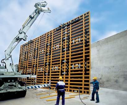
25 3.1. PANEL ASSEMBLIES-GANGS Assembling gangs with CLAMPS saves time because of simply positioning the panels and connecting them with the strike of a hammer. Another important quality of this type of connection is that it allows the panels to be at different elevations because the CLAMPS can be placed anywhere along the panels' perimeter profiles. The panel connection at the edge is secured using the ADJUSTABLE CLAMP. 7 clamps in 10 height 5 clamps in 8 height 3 clamps in 4 height Vertical joint The vertical joints can be connected with both clamp models. The joints with wooden filler between panels will have. Panel height 10 : 4 Clamps. Panel height 8 : 3 Clamps. Panel height 4 : 3 Clamps Adjustable clamp The vertical joints between panels are connected with the following minimum number of adjustable clamps: *Panel height 10 : 3 Clamps in each joint *Panel height 8 : 2 Clamps in each joint *Panel height 4 : 2 Clamps in each joint As a general rule, any joint adjacent to an outside corner should be reinforced with one more Clamp Panel 10 : 4 Clamps in each joint Panel 8 : 3 Clamps in each joint Panel 4 : 3 Clamps in each joint Panel height 8 Panel height 10 When possible, it is recommended to place always the Adjustable Clamp on the panels' rectangular tubes to achieve stronger joints. 25


26 Fixed clamp As a general rule, the vertical joints between panels are connected with the following minimum number of fixed clamps: *Panel height 10 : 4 Clamps in each joint *Panel height 8 : 3 Clamps in each joint *Panel height 4 : 2 Clamps in each joint Detail: WALER connection The external joints in 90º corners between panels cannot be made with this clamp. The following are some examples of different panel heights and gang elevations using the adjustable clamp and walers: Horizontal joint The horizontal joint connection between panels can be achieved, depending on the panels sizes, with ADJUSTABLE CLAMPS or combination of clamps and WALERS. There are three types of WALERS: 0.90m, 1.55m and 1.65m. All walers are fixed to the panel with two WALER HOOKS inserted in the holes in the rectangular tube. 26
27 27
28 28
29 29
30 The fixed clamp is placed on the perimeter profiles of the panels to join them. It does not have any stiffening capacity, thus it almost always will be assembled together with WALERS. Following are some examples of different panel heights and gang elevations. 30
31 31
32 32
33 NOTE - For the configuration of Panel gangs higher than the ones shown in this document, consult with the Technical Department. 33

34 º CORNERS The RIGID INSIDE CORNERS is used on most internal sides of 90º CORNERS although it is also possible to place the HINGED INSIDE CORNERS. The vertical connection of the INSIDE CORNERS is made with the SHORT THREADED ROD 0.35 and two HEXAGONAL NUTS 15 as it is shown in the following diagram. 1 increments by rotating the panel 180º. The holes diagram can be seen below. 55 Wide universal panels 31 Wide universal panels Depending on panel height, the number of U shaped connecting ribs varies as follows: Vertical Corner connection Universal Panel The solution for the external side of 90º corners is made with the UNIVERSAL PANEL. For tying the panels, UNIVERSAL PANEL BOLTS and PLATE WASHER NUTS are used. the universal panels have U shaped ribs with holes in 2 increments and one hole at 3 from the last one ( hole A), the UNIVERSAL PANEL BOLT can pass through any one of these holes. Depending on the chosen hole, the wall thickness will be different. Due to location of the holes, it is possible to adjust the wall thicknesses in NUMBER OF RIBS WITH PANEL HOLES UNIV PANEL 10 6 UNIV PANEL 8 4 UNIV PANEL 4 2 UNIV PANEL 2 1 There are 2 possible configurations: The corner can be solved using a universal panel together with a standard panel. The joint is fastened using the holes of the U shaped ribs of the universal panels, and the lateral holes on the standard panel. 34
35 o o Wall thicknesses (even dimension): letter A in the INTERNAL side of the wall. Wall thicknesses (odd dimension): letter A in the EXTERNAL side of the wall HINGED CORNERS The solution for hinged corners is achieved by combining the HINGED INSIDE CORNER and HINGED OUTSIDE CORNER º - 180º CORNERS The corner can be also solved using two universal panels. The joint is fastened using the holes of the U shaped ribs and the lateral holes of the universal panels. For these cases both types of corners are used in combination. The HINGED INSIDE CORNER is used on the inside angle and the HINGED OUTSIDE CORNER placed on the outside. FILLING o o Wall thicknesses (even dimension): letter A in the INTERNAL side of the wall. Wall thicknesses (odd dimension): letter A in the EXTERNAL side of the wall. FILLING 5 CLAMPS IN 8 35


.")
36 5 CLAMPS IN 8 3 CLAMPS IN 8 The following rules should be taken into account for these solutions: HINGED OUTSIDE CORNER 10. With filler HINGED OUTSIDE CORNER 8. With filler The O.H.C is secured as follows: o 6 Clamps for heights of 10. Whenever Both clamps, FIXED and ADJUSTABLE, can be there is significant filler between joints, used on the external corner taking into account they should be reinforced with 3 that for angles bigger than 130º, the WALERS per side. ADJUSTABLE CLAMPS cannot be placed at the o 5 Clamps for heights of 8. Whenever same level on both sides. They should be placed there is significant filler between joints, in different levels to avoid interference between they should be reinforced with 2 them WALERS per side. The FIXED CLAMP is used for inside corners o 3 Clamps for heights of 4. between 65º-75º. Both Clamps can be used for larger angles. In both cases it is recommended to place them on different levels. For the inside corner, place 3 Clamps for heights of 8 and 2 Clamps for 4 (each side). Likewise, whenever there are significant fillers between panels they should be reinforced with: 3 WALERS and 4 CLAMPS on each side for a height of 10 and 2 WALERS and 3 CLAMPS on each side for a height of 8. HINGED OUTSIDE CORNER 10. Without filler HINGED OUTSIDE CORNER 8. Without filler 36


37 3.4. WALL INTERSECTIONS º WALL INTERSECTIONS HINGED INSIDE CORNER 10. Without filler HINGED INSIDE CORNER 10. With filler The FIXED CORNER or the UNIVERSAL CORNER are used with the different panel widths to solve different wall thicknesses. Depending on the width of the wall we can combine both of them. HINGED INSIDE CORNER 8. Without filler HINGED INSIDE CORNER 8. With filler º - 180º CORNER For this range it is possible to use the HINGED INSIDE CORNERS on both wall faces as shown in the following diagram. WALERS should still be used when there are wooden fillers at the joint, and only CLAMPS can be used if there are no fillers. HINGED INSIDE CORNER HINGED WALL INTERSECTIONS The inside HINGED CORNER is used with the different panel widths to solve different wall intersections at various angles. HINGED INSIDE CORNER 37
, it is not posible to use the UNIVERSAL PANEL BOLTS, in these cases the BULKHEAD BOLT and the")

: letter A is NOT used to tie the panels. Wall thicknesses (odd dimension): letter A is used to tie the panels. 38")
38 3.5. BULKHEADS Bulkhead solutions can be provided in many different ways: With walers To form bulkheads, the WALERS are used in conjunction with the UNIVERSAL PANEL BOLTS and PLATE WASHER NUT 15. In some cases, because of the short distance between the outside profile and the tube (distance A), it is not posible to use the UNIVERSAL PANEL BOLTS, in these cases the BULKHEAD BOLT and the BULKHEAD NUT 15 is used. PANEL NUMBER OF WALERS PANEL HEIGHT 10 6 PANEL HEIGHT 8 4 PANEL HEIGHT 4 2 PANEL HEIGHT With BULKHEAD BOLT and BULKHEAD NUT 15 The BULKHEAD BOLT and BULKHEAD NUT 15 is used when the gang ends with panels of a 1-0 width or the panels are used horizontally With UNIVERSAL PANEL BOLT The WALERS are fastened to the panels by inserting the UNIVERSAL PANEL BOLT through the panels' lateral holes securing them with PLATE WASHER NUT With UNIVERSAL PANEL The UNIVERSAL PANEL is tied to the standard panels with the UNIVERSAL PANEL BOLTS and the PLATE WASHER NUT 15 Depending on the Universal panel that is used, different widths of wall can be achieved. o o Wall thicknesses (even dimension): letter A is NOT used to tie the panels. Wall thicknesses (odd dimension): letter A is used to tie the panels. 38
: letter A is used to tie the panels. o o Wall thicknesses (even dimension): letter A is in the part of the UNIVERSAL CORNER.")
39 3.6. PILASTERS With WALERS: Pilaster solutions: In the middle of the wall With RIGID INSIDE CORNER For this solution the BULKHEAD BOLT and the BULKHEAD NUT 15 are used With UNIVERSAL CORNER With UINIVERSAL PANEL: o Wall thicknesses (even dimension): letter A is NOT used to tie the panels. o Wall thicknesses (odd dimension): letter A is used to tie the panels. o o Wall thicknesses (even dimension): letter A is in the part of the UNIVERSAL CORNER. Wall thicknesses (odd dimension): letter A is in the outside part. 39

40 3.6.2 Pilaster in corners The internal Pilaster corner can be solved in different ways: With RIGID INSIDE CORNER and UHC Use of the UNIVERSAL HINGED CORNER together with the RIGID INSIDE CORNER for the inside. The different pilaster dimensions will be reached by bolting the INSIDE CORNER in one of the holes of the UNIVERSAL HINGED CORNER with the BULKHEAD BOLT and the BULKHEAD NUT With UNIVERSAL HINGED CORNER This solution is very helpful when there are many pilasters close to each other or in any locked in condition. For stripping the panels, there is no need to untie all the elements With UHC and UC Similar to the previous solution but instead of using the RIGID INSIDE CORNER, using the UNIVERSAL CORNER. Combining the UNIVERSAL CORNER with the STANDART PANELS, different widths can be achieved. Pouring concrete Stripping panels 40


41 With UC A different solution using UNIVERSAL CORNERS with STANDART and UNIVERSAL PANELS Universal panel with standard panel For this solution, UNIVERSAL PANELS are placed opposide each other and the holes of the U shaped tube have to coincide COLUMN FORMING Other solutions Column forming is solved using UNIVERSAL PANELS. These panels are connected using UNIVERSAL PANEL BOLTS and PLATE WASHER NUTS 15. As previously explained in the 90º Corners, the universal panels have some U shaped ribs with holes in 2 increments and one hole at 3 from the last one ( hole A), the UNIVERSAL PANEL BOLT can pass through any one of these holes. Depending on the 41
: UNIVERSAL PANEL 55 55 Wide universal panels UNIVERSAL PANEL 31 31 Wide universal panels Depending on panel")
42 chosen hole, the wall thickness will be different. Due to location of the holes, it is possible to adjust the wall thicknesses in 1 increments. The holes diagram can be seen below (same picture previously shown in 90º Corners section): UNIVERSAL PANEL Wide universal panels UNIVERSAL PANEL Wide universal panels Depending on panel height, the number of U shaped ribs is different: The UNIVERSAL PANELS can also be combined to obtain different rectangular dimensions. PANEL NUMBER OF RIBS WITH HOLES UNIV PANEL 10 6 UNIV PANEL 8 4 UNIV PANEL 4 2 UNIV PANEL 2 1 The panels are fastened by the UNIVERSAL PANEL BOLT and PLATE WASHER NUT

 together with STANDARD PANELS.")

43 Column working platform can be built by Universal Column platform, which is fixed to the forwork guarantee a safety lifting of complete set Job built filler 0<X<4 For any wooden filler smaller than 4, the following solutions are possible: TAPER TIE through the fillerl + Plate washer nut The TAPER TIES will be inserted through the wooden filler and the PLATE NUT is placed as support element on the MEGAFORM panels. They are fastened using the ADJUSTABLE CLAMPS. Max. filler between panels: 4 For further information, see Universal Column Platform user s guide OTHER SOLUTIONS These cases are solved using the U.H.C. (UNIVERSAL HINGED CORNER) together with STANDARD PANELS. To joint the UHC to the STANDART PANEL, UNIVERSAL PANEL BOLTS and PLATE WASHER NUT 15 are used TAPER TIE through the panel + Waler The TAPER TIES will be placed through the panel holes and using the WALER 0.90 as support element on its ribs. The fastening between panels is done with the ADJUSTABLE CLAMPS. Tie assembly 3.9. FILLERS Often it is necessary to insert wood filler or COMPENSATION ELEMENTS between panels in order to achieve the required wall dimensions. Depending on the filler size to be inserted, different solutions can be used. The limit of opening of the ADJUSTABLE CLAMP is 4 43


44 3.9.2 Job built filler SLIP PLATE Wooden filler Any filler 4-1 requirements can be solved using wooden filler adapted to the required dimensions. A wooden panel can be made with plywood, cut to the required dimensions and reinforced laterally with WOODEN PROFILE. These wooden reinforcements are joined to the panels with ADJUSTABLE CLAMPS; the TAPER TIES can pass right through the middle of the filler and through the WALER. Fillers between 3 and 1 can be solved by placing the SLIP PLATE in both sides of the wall; they are always used with the panels in vertical position. The proper filler dimension is achieved by cutting back the panels on both sides as much as necessary over the form plate. Thus, the minimum filler measurement is given by the center tube of the SLIP PLATE when the panels are flush against it. In this case the TAPER TIES will be inserted through the PLATES holes, fixing them on the WALERS 0.90 that will be fastened to the panels with the WALER HOOKS. WOOD FILLER COMPENSATION FILLER PLATE PLATE OVERLAP 60 Compensatón FILLER PANEL PANEL 8 PANEL 10 PANEL 44


45 3.10. CORE FORMING To simplify stripping the gang, in aplications like building containers or elevator shafts, it is necessary to use four the RETRACTABLE INSIDE CORNERS. WALL MINIMUM RADIUS PANEL WIDTH (FT.) These values are obtained taking into account that the maximum angle the ADJUSTABLE CLAMP can fasten between panels is 6º. It is necessary to place wooden filler between panels for this type of walls POLYGONAL WALLS Tie assembly Min. Width: 1 1/2 Polygonal walls of the following minimum radius can be made with the MEGAFORM panels. Max. Width:4 45


46 3.12. ADJOINING WALL FORMING Different solutions for different wall cases are shown below: Perpendicular to existing wall 8 or 10 PANEL Overlapping existing wall The conical tie-sleeve in the form allows the sloping of the panels on both sides. For this solution it is necessary to use the BATTERED WASHER. Using just the PLATE WASHER NUT 20, it is also possible to obtain these inclinations. Different solutions are shown below: 8 x8 Panel MAX. WOOD FILLER BATTERED WALLS Inclination up to ( 5º) In these cases the general assembly is the same as the one used for straight walls, but it is necessary to take into account some considerations due to the inclination All the values presented in this section are referred for using panels in their vertical position. For these inclined walls, when pouring, there are vertical forces on formwork panels, which can lift the panels. Thus, before pouring it is necessary to adequately anchor the formwork panels to the ground with the UPLIFT BRACKET to resist such forces. 46


47 Inclination > 10% The FILLER COMPENSATION TUBES should be used for walls where the inclination is greater than 6º. The COMPENSATION TUBES are placed on the joint of two consecutive panels fastening them with ADJUSTABLE CLAMPS. The TAPER TIES should be inserted through the COMPENSATION TUBES instead of passing through the panels. The COMPENSATION TUBES must be placed on both sides, even if the wall is not inclined on one of the sides. The use of PANEL 10 X8 and 8 X8 is not allowed for this solution. With panels in direct contact with the ground, it is necessary to fix the panel using the lower TAPER TIES and HEXAGONAL NUT15 which always should be used with ECCENTRIC WASHER to avoid chrusing into the panel profile. Upper TAPER TIES are fixed by placing the TOP TIE BRACKET 65 over the profile, thus permitting the rod to pass above the concrete level. FILLER TUBE FILLER TUBE FILLER TUBE TOP TIE BRACKET 65 HEXAGONAL NUT 15 + ECCENTRIC WASHER Panels placed on wood sills GRADE BEAM FOUNDATIONS Different situations encountered when placing formwork for foundations are presented below: In this case, it is possible to use PLATE WASHER NUT15 to fasten the lower TAPER TIES supported over the profile and the wood Panels placed on grade When forming footings it is very common to use horizontally placed panels, using TAPER TIES as shown in the following cases. WOOD SILL +PLATE WASHER NUT 15 47


48 3.15. UPPER EXTRAFORMWORK WALERS 0.90, fixed to the upper part of the panels, are used as a base support, and they facilitate certain wooden formwork extensions. These formwork extensions can provide up to 10 of extra formwork on the top side of a wall. formwork TIEs. This is usually on the panel s upper tie hole and therefore, the anchoring system works as the tying element CLIMBING The CLIMBING BRACKET is the base component used as support for the formwork when is necessary to climb. This SIMPLE CLIMBING BRACKET is only used to cover primary climbing needs on low rise walls. When climbing on both sides with high safety level requirements or high heights, T/B CLIMBING BRACKET CF MEGA must be used. In this section we will explain the climbing solution using the cone embedded in the concrete as a supporting element. The SIMPLE CLIMBING BRACKETS are independent from the panel gangs. It is recommended to place a SIMPLE CLIMBING BRACKET approximately every 8. The climbing process comprises the following phases: Place the cones and the TIEs between the panels. The cones are tied through the tie holes of the panels using the CONE-WALER CONECTOR. The length of the TAPER TIE connecting the cones depends on the wall thickness. It will remain in the wall at the end of the process. HEXAGONAL BOLT M24X120 DIN Cone on TAPER TIE This method is only valid when climbing on both sides of the wall, since it is necessary to place the climbing components over the position of some of the CLIMBING HOOK 15 48


49 Once the formwork has been stripped, the CLIMBING HOOK NT15 is inserted in the cones of the wall and fastened with HEXAGONAL BOLT M24X120 The CLIMBING BRACKETS are then placed on the CLIMBING RINGS 15NT. The first face of the gang is lifted and put in place, securing them with the corresponding PIPE BRACES. The CLIMBING BRACKETS are braced in pairs using TUBES D48, FIXED COUPLERS 48 AND SWIVEL COUPLERS 48/48. After the reinforcing steel is installed the other side of the gangs is put in place and connected with TAPER TIES to the opposite gang. 49

50 Cone on plywood For the stripping process, after the gangs are removed the climbing hooks are installed and the bracket assemblies can be moved in position. With this method the anchoring elements are placed in the desired position on the panel s plywood face, and therefore it can be used for climbing on one or both sides of the wall. The advantage of this method is that the position of the CLIMBING BRACKETS on the wall can be better controlled, thus improving the accessibility to the elements and also the safety. 50

51 screw through the hole. In these cases the lost tie rod on the cone should have a plate welded on the end to support the tension loads. In case climbing on both sides of the wall is necessary, the components are arranged as follows: The other steps to follow are identical to those in the previous section ONE SIDED FORMWORK Make a hole in the panels of both faces and fasten the CONE M24/DW15 secure the CLIMBING HOOK NT15 against the plywood using the BOLT M24 to screw through the hole. The MEGAFORM panels can be used as a solution for one side formwork, but due to the special characteristics of this type of project, a specific solution is necessary. For this type of application, please contact ULMA Formwork Inc. Engineering Department. BOTH SIDES CLIMBING If it is only necessary to climb on one of the wall faces, then the components are arranged as follows: Make the holes in the panels of that face and fasten the CONE M24/DW15 placing the CLIMBING HOOK NT15 against the plywood using BOLT M24 to 51
52 4. SYSTEM FEATURES 4.1. CONCRETE PRESSURE The calculation of the concrete pressure on formwork panels is based on the German Standard DIN The pressure diagram is provided below. 52
53 4.2. PANELS WORKING LOADS WALLS PANELS Max. concrete pressure (kn/m 2 ) / DIN (2) Maximum tie load SF per Tie Panel SF Kind of load Group 7 pounds 8 x x4 32 Hydrostatic load (PSF) Constant load (PSF) Hydrostatic load (PSF) Constant load (PSF) 1,250 20, ,650 26, ,250 20, ,650 26, Max. concrete pressure (kn/m 2 ) / DIN (2) Maximum tie load SF per Tie Panel SF Kind of load Group 7 pounds 10 x8 (2x2 tie rods) 80 Hydrostatic load (PSF) 1,600 32, x8 (3x2 tie rods) 80 Constant load (PSF) 1,650 26, x4 (2x2 tie rods) 40 Hydrostatic load (PSF) 1,600 32, x4 (3x2 tie rods) 40 Constant load (PSF) 1,650 26, UNIVERSAL PANELS Panel Kind of load Group 7 10 x55 1,850 8 x55 Constant 1, x31 load (PSF) 1,850 8 x31 1,850 53

54 (2) DIN (Flatness tolerances): The different quality levels of wall surfaces are defined in the following chart. DIN L D: 54


55 4.3. COMPONENTS WORKING LOADS Code Name Picture Working Load Fixed Clamp 3,400 pounds Adjustable Clamp 4,500 pounds Tie Rod 15 Tie Rod 20 * Do not weld or heat the tie rods 20,300 pounds 36,000 pounds Bulkhead Hook 3,400 pounds Hexagonal Nut 15 20,300 pounds Plate Washer Nut 15 20,300 pounds Plate Washer Nut 20 36,000 pounds Wing Nut 20 36,000 pounds Walkway Bracket 25 psf At 8 o.c ORMA Lifting hook CE certificate 3,300 pounds MEGA Lifting hook 8,500 pounds ORMA Platform 2.4X psf The following charts show us the working loads of each component: 55
56 PIPE BRACE and ADJUSTABLE BRACE WORKING LOADS (Tensile and Compression) PIPE BRACE ADJUSTABLE PIPE BRACE 5-8 L WORKING LOAD (pounds) L WORKING LOAD (pounds) 3 8 8, , , ,000 PIPE BRACE ADJUSTABLE PIPE BRACE L WORKING LOAD (pounds) L WORKING LOAD (pounds) , , , ,500 PIPE BRACE ADJUSTABLE PIPE BRACE L WORKING LOAD (pounds) L WORKING LOAD (pounds) 8 10, , , ,950 PIPE BRACE 5-6 ADJUSTABLE PIPE BRACE L WORKING LOAD (pounds) L WORKING LOAD (pounds) , , , ,000 ADJUSTABLE PIPE BRACE (with knee bracing) L WORKING LOAD (pounds) , ,175 56
57 4.4. TYING SYSTEM Taper tie She bolt tie This system allows complete removal of tie from concrete. This system has reusable end bolts with 20 mm inner rod (lost in concrete). No internal spreader. CODE According to length NAME 7/8 Diam.She bolt CODE According to length NAME 7/8 Diam.Taper tie Plate washer nut Plate washer nut 20 CODE NAME CODE NAME Base plate D Base plate D Wing nut Wing nut 20 57


.")
58 5. ASSEMBLY, USE AND DISASSEMBLY This section describes the steps in MEGAFORM gang assembly in detail, describing the different system elements that are used. STEP DESCRIPTION SKETCH 1 Once the preassembly area is cleaned and leveled, place the bottom plank to support the formwork. Use a crane to put the panels on the sills using a certified lifting hook. Then, secure the panels using ADJUSTABLE CLAMPS. 2 Assemble the heads, pipe braces and the pipe brace shoes on the panels. (Section 5.1.). 3 Assemble post brackets on the panels. Once they are placed, assemble the boards on the top and bottom handrails using wooden planks (Section 5.2.). 4 Using a minimum of two certified lifting hooks on the gang (section 5.3.). Lift the gang and move it to the final position. Anchor the pipe brace shoes to the ground using Hilti HAS M20x125 anchors. 58

 6 After the reinforcing steel is installed. Lift the gang and place it opposite of the other gangs.")


59 5 In the preassembly area repeat step 1 with new panels. Place the walkway brackets or working platforms according to the assembly drawing. Different bracket types or working platforms can be used. WALKWAY BRACKET (section 5.4.) ORMA PLATFORM 2.4X1.2 (section 5.6.) 6 After the reinforcing steel is installed. Lift the gang and place it opposite of the other gangs. Install secure the TAPER TIEs to join the gangs. Remove the lifting hooks. These operations require the use of appropriate auxiliary equipment. 7 Using appropriate auxiliary equipment to access the working platform, install corner handrails and begin pouring the concrete. 8 Once the concrete has cured completely, the formwork can be stripped. Access the working platform and secure the gangs with lifting hooks. Remove all the tie assemblies from the gangs to be moved. Make sure that the opposite side gang is secured with pipe braces. After pouring, all the elements should be cleaned. 59


60 6 MEGAFORM 5.1. PIPE BRACES The PIPE BRACES are used for the correct vertical positioning of panels or gangs. They also support temporary loads, as wind loads, during the assembly process. PIPE BRACES are fixed to the head and the shoe using connecting pins and cotter pins included in the head and in the shoe. There are many different types of PIPE BRACES. Depending on the formwork height, the appropriate pipe braces are used in combination. The number of components to place horizontally depends on the formwork height min " - max. 15-9" min. 7-10" - max. 11-6" 60 ±5 º 60 ±5 º min. 3-7" max. 5-7" min. 3-7" max. 5-7" The PIPE BRACES are anchored to the ground with the PIPE BRACE SHOES. They are fastened to the ground using appropriate anchoring elements Pipe brace Pipe brace Pipe brace Pipe brace min. 16-5" - max. 19-8" min. 5-0" - max. 39-0" 60 ±5 º 60 ±5 º PIPE BRACES are attached to the panels using HEAD60 or PIPE BRACE HEAD (type B), which is bolted through the holes in the horizontal and vertical ribs. min. 7-10" - max. 11-6" Pipe brace Pipe brace 5-6 Adjustable Pipe braces: U U U U HD U
 on the opposite side of the WALKWAY BRACKETS.")


61 - MEGAFORM 5.2. POST BRACKET 5.3. LIFTING HOOK This element is always placed in a vertical rib holes, inserting the hook and fastening it with the FIXED PLATE NUT. This bracket is used as support element where the SAFETY HANDRAIL POST is installed as a protection (handrail) on the opposite side of the WALKWAY BRACKETS. The maximum distance between two POST BRACKETS is 6. This element is an auxiliary component for lifting one panel or gangs using a crane. Each hook is designed to lift a maximum load of 3300 pounds, and the maximum recommendable angle between slings is 60º. As a general rule, a minimum of two Hooks should be used when lifting panels or gangs. For panels of 3 0 wide or less, a single hook could be used. The LIFTING HOOK incorporates the EC certification in accordance with the European directive 98/37/CE on machinery and the GS mark from the Construction Committee of the Office for Testing and Certifications in Germany. SAFETY MEGAFORM HANDRAIL S-V HANDRAIL POST POST BRACKET Basic assembly The basic installation can be divided into three phases: The hook Opening WALKWAY BRACKET H > 2 8 MTS. Hold the fixed part of the Hook with one hand and turn the movable part with the other hand. 61

62 The hook placement Place the hook on the panel border profile, so that the Hook claw seats in the profile channel The hook Releasing The Hook is disengaged from the external panel profile The hook Fastening Release the Hook assuring that it is correctly seated in both sides of the panel profile. It is recommended to place the Hook on a rib in order to avoid lateral movements when lifting. Position the sling over the hook, taking into account that this should form a maximum of a 30º angle from the vertical Basic disassembly The hook Opening Hold the fixed part of the Hook with one hand and turn the movable part with the other hand. ULMA has specific documentation about the use, assembly and disassembly for the LIFTING HOOK. This documentation includes the USER'S MANUAL, and it is recommended to follow the instructions provided therein WALKWAY BRACKET The WALKWAY BRACKET, is used to provide support for the walkway from which concrete is poured or other work can be done. This working platform should be assembled on the ground and the whole assembly lifted into place. As general rule, two brackets should be assembled on each large panel. For smaller panels, a maximum distance of 8 is admissible, always assuring that the platforms are properly anchored. The following elements must be used: Handrail planks. Platform planks. Toe boards. WALKWAY BRACKET load capacity: 25 Lbs/sq.Ft. The BRACKETS can be assembled on the panels vertical or horizontal ribs. 62


63 5.4.1 Horizontal ribs The WALKWAY BRACKET is assembled by inserting its main pin in one of the ribs holes and the adjustable element is supported on the lower rib to provide stability. The main pin of the bracket includes a safety cotter pin Basic assembly Adjustable STOP Place wooden planks until covering the working surface, assuring that the 2 supports are correctly secured, thus guaranteeing the planks cannot move. Assemble upper and intermediate wood handrails and toe boards on the safety handrail posts of the walkway bracket. The handrail, post is provided with L shaped elements to support the wooden rails. The wooden toe board is supported on the bottom of platform. It is recommended to use planks which are in good condition. Detail view: pin inserted in the rib and lower adjustable stop supported on lower rib Vertical ribs The WALKWAY BRACKET is laterally bolted in one of the holes of the vertical rib by inserting the PANEL BOLT through the hole in the bracket and fastening with the HEXAGONAL NUT15 on the other side. 63
64 6. SUGGESTED BASIC PROCEDURES FOR ASSEMBLY OF MEGAFORM Important Notice: ULMA is strictly a supplier of concrete formwork equipment. The contractor and their properly trained personnel perform and are responsible for all labor and the safe use of the equipment. Contractor must always observe and work in accordance to the safety regulations, codes, and safety guidelines that apply in the erection, use and handling of Ulma s concrete forming equipment (such as but not limited to: OSHA, Contractor s Safety Programs, ACI, and any others as applicable). Some of the illustrations depicted may indicate or describe situations while under assembly and may not be shown with correct safety precautions in place. Contractors must excercise and apply safety precautions at all phases of the work. This suggestive compilation is intended to be a general guideline for safely assembling and using Ulma s Megaform System. Contractor is responsible to have adequately trained and experienced personnel in the use of concrete forming equipment and knowledgeable in concrete construction. Upon request, should the contractor require it, Ulma can provide personnel to review the assembly of Ulma s concrete forming equipment on site or their offices. Ulma s equipment should never be used with another manufacturer s as it could create a dangerous and unsafe situation. Should there be a question or concern by the contractor, contact Ulma s Technical department immediately. SAFETY IS EVERYONE S PRIMARY CONCERN UNLOADING TRUCKS A maximum bundle of 6 each 8 x 8 panels (about 5000 pounds), or 5 each 8 x 10 panels (about 5,300 pounds) can be safely lifted with four (4) Panel Lifting Hooks. Four (4) slings with a rated safe working load of at least 2000 pounds per sling (supplied by contractor) at least 12 long should be used with the Panel Lifting Hooks. When moving loads of multiple panels, always safely strap them together to avoid dropping part or the entire load. 64

65 Secure the load by strapping bundled forms together Panel Lifting Hook When lifting, fully engage the rails with the Panel Lifting Hook by having the tab in the UP position and fully touching the form rail. Appropriate shackle with 1 Dia. Pin max., lifting hook and chain by contractor. Panel Lifting Hook (2,000 # MAX. SWL) NEVER STAND BELOW A LOAD AND ALWAYS KEEP A SAFE DISTANCE TO SAFEGUARD AGAINST SUDDEN OR UNEXPECTED LOAD MOVEMENTS. LIFT PANELS GENTLY AND USE TAG LINES. 65
66 FORM ASSEMBLY Select and prepare a clean and flat staging area where there s a good view of the crane operator. Presort, identify and count equipment in anticipation of assembly. Area should be close to where the forms will be erected. The form assembly area does not have to be sophisticated but should be relatively level. Planks should be spread out on the ground where form panel joints meet so that they line up correctly. Contractor should have adequate hoisting equipment as well as Key Personnel that are knowledgeable in the use of concrete formwork and can lead the workers in the safe and correct use of concrete forming equipment. UPON REQUEST BY THE CONTRACTOR, ULMA HAS PERSONNEL AVAILABLE TO THE FIELD FORCES AND/OR CONTRACTOR S OFFICES THAT CAN REVIEW THE BASIC PROCEDURES FOR ASSEMBLY OF ULMA S CONCRETE FORMING EQUIPMENT. Using panel lift hooks, set panel on planks and align with adjacent panel. Locate clamps as per the erection drawing and tighten by hammering the wedge until tight. Work the assembly by joining panels from center of gang to outside of gang. Locate the stiffener wale as per erection drawing and tighten short waler hooks. The stiffening waler should be placed on the side of the rail that faces the center of the panel to avoid interfering with the clamp placement along the outside form rails. Continue process until appropriate size gang is complete. Install additional components (scaffold brackets, pipe braces, etc.) as per the erection drawing. The basic tools required for assembly and working of the form include but are not limited to carpenters hammers, adjustable wrenches, pry bars, masonry drill with ¾ bit, expansion anchors and form release agents. Under no circumstances should any form rail or rib be hit directly with a hammer or sharp object. If necessary to strike the form for any reason PLEASE use a woodblock at point of impact. Safely use the adjustable clamps as you would any other connecting device. In excessive gaps between panels in the process of assembly, do no beat on one clamp to pull the forms together but walk it over instead. Work the clamps sequentially; let them do the work for you. Once the forms are assembled or being cycled, always be aware of using the proper quantity of Gang Lifting Hooks in conjunction with the proper rigging (slings, lifting beams, taglines, etc.) and always keep a safe distance from any pick based on your firms safety procedures and any other governing regulations. To avoid undue strain on the horizontal joints, the form should not be laid down on the ground in sections greater than 24 high. 66
67 GANG LIFTING HOOKS Each Standard Hook has a safe lift capacity of 3,300 lbs. Using two Standard Hooks, gangs can be pre-assembled on the ground in units no larger than 16 high x 24 long, and then lifted to a vertical position. The sling length should be a minimum of 14 long when picking the gang and the LIFTING HOOKS must always be fully connected. SEE LIFTING HOOH SAFETY RULES. Each MEGAHOOK has a lift capacity of 8,500 lbs. Using two MEGAHOOKS, large gangs can be pre-assembled on the ground in units no larger than 24 high x 40 long, and then lifted to a vertical position. The sling length should be a minimum of 24 long when picking the gang. Megahooks can only be used on certain panels and at specified locations. See erection drawing or contact ULMA s Technical Department. SETTING THE GANG FORM Spray the form face with the release agent (always clean and apply release agent between pours). A starter shoe is not necessary as long as the footing or landing surface is relatively smooth. Guide blocks or hold down brackets can be used to spot the gang at the correct wall line. Set the gang down and install hold down brackets with a ¾ expansion anchor in the concrete footing (optional). Safely anchor pipe braces to adequate dead men or equivalent to prevent a collapse of the gang prior to releasing the crane. Prior to releasing the crane, use a 6 level or equivalent to plumb the gang forms. Final adjustments should be made prior to closing the walls and definitely before placing concrete. Pipe braces should have the screw preset halfway, this facilitates the pulling or pushing of the form without running out of screw and resetting when plumbing the gangs. When setting or stacking any additional panels or gangs on top of a previously set gang, safely clamp joints together, install any other required stiffeners, ties, or necessary hardware then, support and plumb with pipe braces the additional equipment as required. (Refer to form erection drawings for locations or contact ULMA s Technical Department). STRIPPING AND MOVING Strip bulkheads and remove ties leaving always one until the gang form is secured to the crane. Break the bond between the concrete and form using wood wedges to prevent damage to the face of the form. Using lifting hooks as described above and all safety precautions per contractor s safety program and all other governing regulations. 67
68 PIPE BRACES Pipe Braces are generally shipped with keeper pins (L-pin) in the pipe brace head. Use this pin to join the upper and lower pipe sections together. Use a 20 (8 ) panel bolt with hex nut to connect the pipe brace head to the form. Contractor to adequately brace one side of the gang forms against wind loads, impact of placing concrete, and live load of personnel working on the forms. Follow the suggested spacing on Ulma s layout drawings when provided or contact Ulma s Technical Department. TIES The top row of ties can generally be eliminated if you are using top yokes. When closing up a wall, contractor should use temporary spreaders to ascertain that the correct wall width has been set. Overtightening of the ties can draw the forms in causing a reduced wall width and the wall to become hourglass shaped. TAPER TIES If using Taper ties, to avoid confusion as to which end of the taper should be extracted from the finished pour, the wide ends of the taper ties should always be on the same side of the form gang. Please grease the smooth shoulder of the taper ties so it easily strips without causing costly damages to the contractor. SHE-BOLTS If using she-bolts, the inner rod length should be cut 4 shorter than the wall thickness. Screw one she-bolt onto each side of the inner rod until it bottoms out. Place the appropriate washer and wing nut on one end and insert through tie holes. Place the other complimenting washer and wing nut on and snug up. When wing nuts are screwed snug against the wide part of the washers, the proper length has been attained. INNER UNIT WATERSTOPS Waterstops are supplied loose, contractor to slip them on to the inner unit to the halfway point. The common name for this ring is waterstop however cast concrete will experience shrinkage, improper bonding, cracks and voids around stress points, all key factors that can cause leaks around tie inner units. As such, these rings while providing an initial seal in most cases are by no means a guarantee that there will not be a leak and contractor should be aware. It s for this reason that there s no implied guarantee of having walls watertight through the use of these products as manufactured by any supplier. The ultimate responsibility of waterproofing a wall is the contractor s. INSIDE CORNERS Use 14 long she-bolts with flat washers on inside, or raise filler next to inside corner with a wood sill to avoid taper tie crossing interferences. 68
69 GANG CONFIGURATIONS Keep vertical stiffener wales towards the inside of panels when installing. This gives extra clearance for attachment of clamps when adjoining adjacent gangs. Although our engineered drawings indicate the location of the walkway brackets, contractor to determine in the field as to their preferred location prior to installing these other accessories (clamps, horizontal stiffeners, pipe braces, etc.) to avoid interferences. This can save time in unnecessary removal of the accessories. SANDWICHING SMALL PANEL (2 -O MAX.) SETUPS BETWEEN LARGE PANELS CAN MINIMIZE VERTICAL STIFFENER WALES. (I.E REQUIRES ONE STIFFENER ACROSS HORIZONTAL JOINT.) SOME BASIC SAFETY SUGGESTIONS Inspect all equipment before using. Never use equipment that appears damaged. If damage develops in any equipment, discontinue use immediately and contact Ulma Form Works, Inc. to have it repaired or replaced. All joints, which are not held by ties, must be waled and braced. Before placing concrete, the contractor should have assigned personnel checking both sides of the wall to make sure that all ties and bolted connections are properly secured and in place. Assure that all clamps and stiffener walers are maintained tight and secure and in proper positions. Protective devices such as goggles, gloves, steeltoed shoes and safety harness must be worn when working with forming systems. The contractor must provide safe access to the walkways and other areas of the forms. Forms are not designed to be climbed. It is the contractor s responsibility to supply adequate planking, guardrail systems and/or fall protection devices as required complying with their own safety programs and any other governing regulations. If tie-off to the Formwork is required by the contractor, the MEGAFORM accessory holes located in the panel ribs meet OSHA code requirements for the tie-off points of personal safety equipment and/ or fall protection devices, when used in conjunction with a large size locking rebar snap hook and safety harness. When in use, the hook must engage fully (through the hole in the panel rib) and keeper must close and lock. MEGAFORM panel handles meet OSHA requirements for fall protection when used in conjuction with selfretracting life lines, lanyards and positioning device systems limiting free fall distance to 2 feet. Standard practice for placing concrete and standard vibrating procedures must be followed. Concrete should not be dropped without the use of an elephant trunk. Vibration should be limited to 4 feet below top of concrete surface, and vibrators should not be used for moving concrete laterally (see ACI 347). Serious injury may result if the contractor fails to use safe practice in the erection, dismantling or use of the forming equipment. The contractor must be familiar with and follow correct laws and regulations at all times. 69
70 7. LEGAL AND STANDARD REFERENCES ON THE PREVENTION OF OCCUPATIONAL AND ENVIRONMENTAL HAZARDS 89/391/EEC Directive Health and Safety in the Workplace 89/654/EEC Health and Safety in the Workplace 92/57/EEC Health and Safety at Construction Sites 92/58/EEC Health and Safety Signposting in the Workplace 89/655/EEC, 95/63/EC, 2001/45/EC Using Work Equipment 89/656/EEC Personal Protective Equipment (PPE) 90/269/EEC Manually Handling Loads 2002/44/EC Risks Derived from Physical Agents (Vibrations) 2003/10/EC Risks Derived from Physical Agents (Noise) UNE-EN 13374: Temporary border protection systems, product spe 70

71 ULMA C y E, S. Coop. Ps. Otadui, 3 - P.O. Box OÑATI Spain T F
PERFORM WITH PRECISION MAX A FORM STS FORMING SYSTEM CONCRETE CONSTRUCTION PRODUCTS APPLICATION GUIDE
 MAX A FORM STS FORMING SYSTEM PERFORM WITH PRECISION CONCRETE CONSTRUCTION PRODUCTS APPLICATION GUIDE A WORD ABOUT SAFETY High productivity depends on safety; even a minor accident causes job delays and
Big expertise. Real convenience. Concrete commitment. stem
 1300 659 830 www.formdirect.com.au Big expertise. Real convenience. Concrete commitment. Stee l Pre-e P n g i n eere ly Fo conc d rete form, factory rmin ing s ystem built, re-u g sy sable stem Steel-Ply
PUSH-PULL-PROPS. and accessories ROBUSTA-GAUKEL GMBH MOUNTING TECHNOLOGY &CO.KG
 PUSH-PULL-PROPS and accessories MOUNTING TECHNOLOGY ROBUSTA-GAUKEL GMBH &CO.KG MOUNTING TECHNOLOGY PUSH-PULL-PROPS AND ACCESSORIES INDEX General information...................... 3 Push-pull-prop Type
How to Use the Jahn Forming System
 How to Use the Jahn Forming System 1. Preparation Gang drilling the plywood is the only preparation required. Holes need to be drilled 1/8" larger than the snap tie head. Normally, a 5/8" diameter drill
February 2004 RONDA. Circular Formwork Instructions for assembly and use
 February 2004 Circular Formwork Instructions for assembly and use Table of Contents Product Features 2 General Survey 3 Components 4 7 Measures of Ronda Elements 8 9 Adustment of Radii 10 11 Connections
Acrowall-60 General Technical and Application Manual
 FORMWORK PRODUCT Technical Guide Acrowall-60 General Technical and Application Manual Genuine Safety. Outstanding Service. Acrowall-60 Formwork System Important The erection and application instructions
Meva Guided Screens MGS Technical Instruction Manual
 Meva Guided Screens MGS Technical Instruction Manual Product Characteristics: The MEVA Guided Screens (MGS) system encloses complete floors especially in high-rise construction independent of the height
THE POWER OF RED STEEL-PLY CONCRETE FORMING SYSTEM APPLICATION GUIDE
 THE POWER OF RED STEEL-PLY CONCRETE FORMING SYSTEM APPLICATION GUIDE Table of Contents Introduction...1 Handles...1 Components...1 Safety Eyes...1 Fillers... 2 Wedge Bolts... 2 Steel Fillers and Long
Sure-P ure l -P y l APP A lic PP A lic tion A G tion uide G
 Sure-Ply Application Guide PRODUCT FEATURES Exact corner joints eliminate tolerance build-up over large areas. 1000 PSF System All panels are powder coated. In doing so the paint is baked into the panel
MEP Shoring System Technical Instruction Manual
 MEP Shoring System Technical Instruction Manual The MEP Shoring System is a versatile yet simple system capable of handling virtually any project with only two basic components: The post shore and the
Sure-P ure l -P y l APP A lic PP A lic tion A G tion uide G
 Sure-Ply Application Guide PRODUCT FEATURES Exact corner joints eliminate tolerance buildup over large areas. 1000 PSF System All panels are powder coated. In doing so the paint is baked into the panel
Experience the Hi-Lite Advantage
 Experience the Hi-Lite Advantage 12K Aluminum Shoring System INTRODUCTION The 12K Shoring System is primarily a hand-set system. It can also be handled with a crane, and may also be used quite successfully
Clamping devices 521
 Clamping devices 521 522 Product overview Clamping devices Adjustable straps K0001 Hook clamps K0012 Goose-neck straps with long slot K0002 Page 526 Hook Clamps with collar K0013 Page 535 Equipped clamps
Scaffolding ACCESSORIES
 Scaffolding ACCESSORIES INITIA COMPONENTS FIXED BASE For flat surfaces. With holes in the spigot for attaching the cradle head. The reinforced base plate has a thickness of 5 mm and a surface area of 120
6.1. PUSH-PULL-PROPS and accessories
 6 6.1. PUSH-PULL-PROPS and accessories MOUNTING TECHNOLOGY 6 GENERAL INFORMATION PUSH-PULL-PROPS AND ACCESSORIES INDEX General information....................... 3 Push-pull-props Type R.....................
Leveling Feet, Base Plates and Casters
 Leveling Feet, Base Plates and Casters 77 Leveling Foot 1 1 Fastening to profile end Fastening in T-slot of profile For leveling tables and light equipment. Ratchet-type height adjustment requires no tools.
Imperial Technical Instruction Manual
 Technical Instruction Manual The wall formwork is a cranedependent modular formwork system for use in industrial and civil engineering projects as well as administration and residential building construction.
Lok Fast Column Clamp General Information
 Lok Fast Column Clamp General Information Gates Lok-Fast Column Clamp Has These Advantages: Can Be Job Built Gang Formed No Loose Pieces Designed For Rapid Placement of Concrete Rapid Locking Action 3
GLOSSARY OF TERMS SECTION 8
 GLOSSARY OF TERMS SECTION 8 Anchor Bolt Angle Base Plate Bay Blocking CCB Centerline Chord Cladding Clip Closure Strip An A-307 steel bolt embedded in the concrete footing to anchor the base plate of the
WAL-MART SUPERCENTER # ; Milwaukie, OR: SPECIFICATIONS. Revisions to Specification Fence
 MILWAUKIE OR #3144-00 ADDENDUM #5 NARRATIVE: 11-08-12 WAL-MART SUPERCENTER #3144-00; Milwaukie, OR: SPECIFICATIONS SPECIFICATIONS Revisions to Specification 02822 Fence Spec division 02822 has been revised
MM340 Installation Instructions IMPORTANT SAFETY INSTRUCTIONS - SAVE THESE INSTRUCTIONS
 MM30 Installation Instructions IMPORTANT SAFETY INSTRUCTIONS - SAVE THESE INSTRUCTIONS Please read this entire manual before you begin. Do not unpack any contents until you verify all requirements on PAGE.
APPENDIX FENCE GENERAL NOTES
 APPENDIX FENCE GENERAL NOTES 1. Fabric: 9 gage, 2" mesh, knuckle top and bottom, placed on the outside of posts, single fabric width for the entire height. 2. All fencing to be standard galvanized finish.
SPACE-LIFT DAYTONSUPERIOR.COM APPLICATION GUIDE. Jump Forming System
 SPACE-LIFT Jump Forming System APPLICATION GUIDE The Space-Lift system is a fully-engineered jump form system intended for concrete shear wall applications. The system consists of frame components and
MM540 Installation Instructions IMPORTANT SAFETY INSTRUCTIONS - SAVE THESE INSTRUCTIONS
 MM50 Installation Instructions IMPORTANT SAFETY INSTRUCTIONS - SAVE THESE INSTRUCTIONS Please read this entire manual before you begin. Do not unpack any contents until you verify all requirements on PAGE.
CertainTeed INSTALLATION GUIDE SIMTEK FENCE PRODUCTS. Fence Installation Guide 3', 4' & 6' High
 CertainTeed INSTALLATION GUIDE SIMTEK FENCE PRODUCTS Fence Installation Guide 3', 4' & 6' High INSTALLATION GUIDE These instructions are designed to assist both professional installers and do-it-yourselfers
MEP Shoring System Technical Instruction Manual
 Shoring System Technical Instruction Manual Product features The shoring system is a versatile yet simple system capable of handling virtually any project with only a few basic components: props, extensions
Oxford Stalls Installation Instructions
 Oxford Stalls Installation Instructions RAMM Horse Fencing and Stalls 13150 Airport Hwy. Swanton, OH 43558-9615 1-800-434-8456 Rev. 8/15/17 Before You Start Typical stall sizes are 10 x 10, 12 x 12 or
Steel-Ply DAYTONSUPERIOR.COM. Forming System
 Steel-Ply Forming System The Steel-Ply forming system is a pre-engineered, factorybuilt, reusable concrete forming system. It may be used in handset or gangform applications, for commercial or residential
MevaDec. Contents. Ref. No. Description / Application Product m² list kg
 Ref. No. Description / Application Product m² list kg This product list includes all parts necessary for most applications. For parts required for special applications, please refer to the MEVA price list.
ALUMINUM PIPE GUIDERAIL 01/01/
 NOTES PIPE RAILING & POSTS: Structural Tube, Pipe and Bar shall be in accordance with ASTM B22 or ASTM B429, Alloy 606-T6. End Rail 90 bends and corner bends with maximum 4-0" post spacing, may be Alloy
THE POWER OF RED SPACE-LIFT CONCRETE CONSTRUCTION PRODUCTS APPLICATION GUIDE
 SPACE-LIFT THE POWER OF RED CONCRETE CONSTRUCTION PRODUCTS APPLICATION GUIDE A WORD ABOUT SAFETY High productivity depends on safety; even a minor accident causes job delays and inefficiency, which run
6o ft (18.3 m) Southwest Windpower, Inc West Route 66 Flagstaff, Arizona USA Phone: Fax:
 Southwest Windpower, Inc West Route 66 Flagstaff, Arizona USA Phone: Fax:") 6o ft (18.3 m) sectional MONOPOLE TOWER INSTALLATION MANUAL Southwest Windpower, Inc. 1801 West Route 66 Flagstaff, Arizona 86001 USA Phone: 928.779.9463 Fax: 928.779.1485 www.skystreamenergy.com 3-CMLT-1390-01
6o ft (18.3 m) sectional MONOPOLE TOWER INSTALLATION MANUAL Southwest Windpower, Inc. 1801 West Route 66 Flagstaff, Arizona 86001 USA Phone: 928.779.9463 Fax: 928.779.1485 www.skystreamenergy.com 3-CMLT-1390-01
Simotec. 13.i
 Products: Framo 80 13.0 Products: Framo 80 13.1 Products: Structural Elements 100/120 13.2 Products: Pipe Shoes 13.3 Framo 80: Beam Section and Screw 13.4 Framo 80: Cantilever Bracket and End Support STA
SECTION CHAIN LINK FENCING AND GATES AND SOFTBALL BACKSTOP
 1 1 1 0 1 0 1 0 1 SECTION 1 1 CHAIN LINK FENCING AND GATES AND SOFTBALL BACKSTOP BASED ON DFD MASTER SPECIFICATION DATED /01/ P A R T 1 - G E N E R A L SCOPE The work under this section shall consist of
BY DAYTON SUPERIOR. Steel-Ply FORMING SYSTEM
 BY DAYTON SUPERIOR Steel-Ply FORMING SYSTEM Steel-Ply Forming System The Steel-Ply forming system is a pre-engineered, factory-built, reusable concrete forming system. It may be used in handset or gang
1.1. THREADED SLEEVES for different fixing purposes
 .. THREADED SLEEVES for different fixing purposes ANCHORING TECHNOLOGY GENERAL INFORMATION INDEX General information...................................... Installation-kits D&W 5 mm...............................
Dura-Lock Roof System
 DLR-14 Dura-Lock Roof System Assembly and Installation Instructions Read the instructions before starting the job. They explain the steps required to produce a finished product that will meet factory specifications.
Precision Steel Car s 100 T Steel Coil Car
 Precision Steel Car s 100 T Steel Coil Car Precision Steel Car www.precisionsteelcar.com info@precisionsteelcar.com Paul Vernon: (513) 571-5739 Revised 4/30/2009 Contents of Kit Main Tube Side Frame 2
Pull-down clamps. No Low height clamping jaws, model Bulle
 Pull-down clamps The wedge action of clamping jaws is the characteristic feature of these pull down clamps. It causes the pull down effect, which presses the workpiece against both, stop and machine table.
STEEL PIPE GUIDERAIL 01/01/
 NOTES PIPE RAILING & POSTS: Pipe Rails and s shall be in accordance with ASTM A5 Grade B for standard weight pipe and ASTM A500 Grade B, C or D or ASTM A50 for structural tube. Bars for handrail supports
CIC 200 PLASTIC SCREW ANCHOR ASSORTMENT WITH PHILLIPS BINDING HEAD METAL SCREWS. 6 x 3/4 P/N x 1 METAL SCREW P/N x 3/4 METAL SCREW
 A21-1 1160 CIC 200 PLASTIC SCREW ANCHOR ASSORTMENT WITH PHILLIPS BINDING HEAD S For light duty applications in solid materials Color coded diameters for easy identifi cation Acid resistant NYLON FLANGED:
PART MATERIALS. Section Fencing Materials. Description
 PART 03000 - MATERIALS Section 03010 - Fencing Materials Description 03010.00 Scope - This section consists of the test requirements, specifications and tolerances for barbed wire, woven wire and chain
Thread protection accessories are installed at the MODIX production factory and delivered with couplers.
 Installation of MODIX Rebar Coupler Identification of the product The type of MODIX Rebar Coupler can be identified by the marking on the product. Size of the Coupler can be identified also according to
INSTALLATION INSTRUCTIONS
 INSTALLATION INSTRUCTIONS SOLID PHENOLIC TOILET PARTITIONS 1080 DuraLineSeries Class-A Fire Rated Includes Institutional Hardware Option.67 IMPORTANT: Storage and Handling Information on last page. Review
Khathij Industrial Fasteners
 Dear Sir/Madam, Khathij Industrial Fasteners This is Saqubar Sadique representing 'KHATHIJ INDUSTRIAL FASTENERS' from Chennai, India. We 'Khathij industrial fasteners' like to introduce us as a Stockist
FOR PROFESSIONAL GARAGE DOOR INSTALLERS
 Composite Garage Doors Installation Instructions FOR PROFESSIONAL GARAGE DOOR INSTALLERS Tools required Screwdriver Claw Hammer Locking Pliers Power Drill Level with a 3/32" Drill Bit Utility Knife 9/16",
Copper Tubing Hangers Clevis Hangers. Copper Tubing Hangers
 Copper Tubing Hangers Clevis Hangers Copper Tubing Hangers Fig. CT-69 Adjustable Swivel Rug Fig. CT-138R Fig. CT-65 Fig. CT-109 Extension Split Light Weight Adjustable Clevis Fig. CT-99 & CT-99C Split
CONTENTS TOOL LIST U P S I D E I N N O V A T I O N S, L L C RAMP AND STEP SYSTEM ASSEMBLY INSTRUCTIONS. Revised: June 2013
 U P S I D E I N N O V A T I O N S, L L C RAMP AND STEP SYSTEM ASSEMBLY INSTRUCTIONS TOOL LIST Required Tools: - Reciprocating Saw with Metal Cutting Blade - Drill - 7/16 Drill Bit for Metal Drilling -
Please read and understand the OnBoard Timpani Cart Owner s Manual before using the Timpani Cart.
 Assembly and Owner s Manual OnBoard Timpani Cart Performance Position Towing Position CONTENTS Important User Information...........................2 General......................................2 Manufacturer.................................2
INSIDE PANEL NOT SHOWN TO DETAIL ANCHORING SYSTEM
 SIX INCH ALPHA MODULE INSTALLATION KEWAUNEE SCIENTIFIC CORPORATION SIX INCH ALPHA MODULE ANCHORING SYSTEM After Alpha module has been set in desired location. Adjust the four adjustment bolts until the
INSTALLATION MANUAL IOWA MOLD TOOLING CO., INC. BOX 189, GARNER, IA MANUAL PART NUMBER:
 PARTS-1 Model 24562/28562 Crane INSTALLATION MANUAL IOWA MOLD TOOLING CO., INC. BOX 189, GARNER, IA 50438-0189 641-923-3711 MANUAL PART NUMBER: 99903701 Iowa Mold Tooling Co., Inc. is an Oshkosh Truck
STOP. V00029AC Rev. 04 READ ALL OF THE FOLLOWING INSTRUCTIONS BEFORE REMOVING CABINET FROM SKID TOOL LIST. NET-ACCESS S-Type Network Cabinets
 Rev. 04 STOP READ ALL OF THE FOLLOWING INSTRUCTIONS BEFORE REMOVING CABINET FROM SKID NET-ACCESS S-Type Network Cabinets -Phillips screwdriver -Flatblade screwdriver -22mm socket wrench -15mm socket wrench
Downtown Rack. Custom logo option available
 Custom logo option available Downtown Rack The Downtown Rack uses thick, square-tube construction that can t be cut with a pipe cutter. The extended width of the Downtown Rack makes for easy bike parking
Index Pipe Hangers and Straps
 Index Pipe Hangers and Straps Fig. 1 Standard Clevis Hanger MSS-SP-69, Type 1 WW-H-171E, Type 1 Page 14 Fig. 1CI Clevis Hanger for A.W.W.A. Page 16 Fig. 81 Clevis Hanger WW-H-171E, Type 12 Page 70 Fig.
No. 412, 414, 416 Operations Manual
 No. 412, 414, 416 Operations Manual CARE: Occasional oiling of moving parts with machine oil will ease operation and extend the life of the brake. Occasionally check and tighten the lower beam bracket
5/16" Flange nut. Bolt Keeper Plate (8" Sq. SYS.) (3) 1/2" x 3" Hex head connector zinc plated bolt w/ washers and nut. Anchor 3" sq. 7 Ga.
 (3) 1/2 x 3 Hex head connector zinc plated bolt w/ washers and nut. Anchor 3 sq. 7 Ga.") 2 1/2" x 2 1/2" x 10 Ga. 6" 5" 4" Variable Slipbase (8" Sq. SYS.) 5/16 Corner Bolt W/ nut 5/16" Flange nut Stub Insert (8" Sq. SYS.) Bolt Keeper Plate (8" Sq. SYS.) (3) 1/2" x 3" Hex head connector zinc
2 1/2" x 2 1/2" x 10 Ga. 6" 5" 4" Variable Slipbase (8" Sq. SYS.) 5/16 Corner Bolt W/ nut 5/16" Flange nut Stub Insert (8" Sq. SYS.) Bolt Keeper Plate (8" Sq. SYS.) (3) 1/2" x 3" Hex head connector zinc
Dublin Stalls Installation Instructions
 Dublin Stalls Installation Instructions RAMM Horse Fencing and Stalls 13150 Airport Hwy. Swanton, OH 43558-9615 1-800-434-8456 Rev. 9/13/17 Part Identification Round Track Bracket (4) (Not Painted) Round
Technologies, Inc. Installation Instructions for Anchors & Components. Rev PAGE 1 / 11
 Installation Instructions for Anchors & Components PAGE 1 / 11 GROUND ANCHOR INSTALLATION INSTRUCTIONS NOTE: 1) The tensioning bolt can be inserted in the head from either side. 2) In areas of severe cold
System 3000 specifications
 System 3000 specifications Scope: Materials: Type of Bookstack: This specification covers delivery and installation of steel library shelving of the bracket type. Height, depth and accessories shall be
H20 Beam for Elevated Slabs Application Guide
 H20 Beam for Elevated Slabs Application Guide A WORD ABOUT SAFETY High productivity depends on safety; even a minor accident causes job delays and inefficiency, which run up costs. That s why Symons, in
Assmann Corporation of America TANK INSTALLATION AND USE GUIDELINES FOR BULK STORAGE TANKS
 Assmann Corporation of America TANK INSTALLATION AND USE GUIDELINES FOR BULK STORAGE TANKS General Information Assmann polyethylene storage tanks are manufactured to give you the toughest, most reliable
IF YOU DON T SEE IT HERE
 www.smithfast.com Drills & Taps & Bits Screws Cotter Drilling Bolts / Hex Capscrews Lag Carraige Hitch Grade 8 Machine Grade Elevator 5 Sheet Spring Metal Roll Grade Eye 2 Square Taper Head set A325 Hex
AUXILIARY FRAMING AND ACCESSORIES
 CUSTOM CABINETS & RACKS STRUT AND ACCESSO- RIES JUNCTION KITS ANGLE AND BRACE KITS SPLICE KITS BRACE KITS INSTALLATION KITS WALL ANGLE KITS RUBBER END CAPS SUPPORT INSTALLATION AND SUPPORT KITS STANCHION
Fastener Type Chart. Fastener Categories. Sheet Metal Screws Fully threaded screws with a point for use in sheet metal. Abbreviated SMS.
 Fastener Categories Wood Screws Machine Screws Thread Cutting Machine Screws Screws with a smooth shank and tapered point for use in wood. Abbreviated WS. Screws with threads for use with a nut or tapped
Adjustable Feet Castors Accessories for Floor Elements
 Adjustable Feet Castors Accessories for Floor Elements Products in this section Levelling Knuckle Feet Threaded spindles for infinite height adjustment Metal or plastic foot plate Knuckle Feet X Compatible
CAM SYSTEM. Eccentric self-locking clamping devices. Set. CAM SYSTEM t. CAM SYSTEM t. Set. CAM SYSTEM s pag CAM SYSTEM s pag.
 Eccentric self-locking CAM SYSEM Set CAM SYSEM t pag. 12 CAM SYSEM t pag. 126 Set CAM SYSEM s pag. 127 CAM SYSEM s pag. 128 EDGE CLAMP pag. 130 123 CAM-SYSEM eccentric self-locking he CAM SYSEM has been
BEST PRACTICE GUIDE. Socket Bases. Working with Concrete Slabs
 Working with Concrete Slabs When working with concrete slabs the barrier protection can be erected in three ways - with socket bases, adjustable slab edge brackets and multi slab clamps. Socket Bases 1
SCHACHT STANDARD FLOOR LOOMTM
 SCHACHT STANDARD FLOOR LOOMTM FL3109 FL3111 FL3113 FL3115 FL3121 FL3123 FL3125 FL3127 FL3310 FL3312 FL3314 FL3316 FL3322 FL3324 FL3326 FL3328 Assembly instructions LOW CASTLE LOOM IN MAPLE Find out more
Installation Instructions
 Column & Beam Units with Debris Netting Installation Instructions Laminated Wood Systems, Inc. Seward, Nebraska 800-949-3526 2015 LWS, INC. AVR-NET INSTALL 05-12-16 AVR Installation Notes 1 Safety The
Cable Runway. Telco-Style Cable Runway. UL Classified Cable Runway
 Cable Runway Universal-style 250 cable runway. The maximum load capacity when supported every 5 with minimal deflection is 132 Lbs/ft Welded steel tubing construction, individually boxed. Overall length
Installation Instructions
 EZ Launch Accessible Transfer System Installation Instructions Models 500900L, 500900R, 500901L, 500901R 500890, 500906L, 500906R For questions about features, operation/performance, parts, accessories
Linear Motion and Assembly Technologies Aluminum Framing /07. Die-Cast Foundation Brackets 3-10 & 3-11
 -0 Linear Motion and ssembly Technologies luminum Framing 91 500 1 /07 Section : Profile onnectors Overview One of the greatest strengths of the osch Rexroth structural aluminum framing system is the wide
Copyright 2008 Robert Conroy
 Copyright 2008 Robert Conroy 24 Diameter Dome This is a precision structure. One must use precise jigs in its fabrication. The measurement tolerances are 1/32", while the overall tolerances are 1/16".
MantelMount. TM1A Installation Instructions IMPORTANT SAFETY INSTRUCTIONS - SAVE THESE INSTRUCTIONS
 MantelMount TMA Installation Instructions IMPORTANT SAFETY INSTRUCTIONS - SAVE THESE INSTRUCTIONS TM Thank you for choosing the MantelMount television wall mount. Please read this entire manual before
Kwik-Lock. Installation Instructions. Attention Dealers: Please give this owners manual to the customer when the product is delivered.
 Serving the Truck & Trailer Industry Since 1944 Installation Instructions Attention Dealers: Please give this owners manual to the customer when the product is delivered. Call 800-535-9545 www.aeroindustries.com
Spiral Slide
 IMPORTANT Page 1 PLEASE READ THESE INSTRUCTIONS BEFORE COMMENCING ASSEMBLY. All equipment must be installed in accordance with these instructions. Check your shipment against Bill of Lading and Parts list.
Installation Instructions
 Installation Instructions For Models: Model Number / Description File Name 1540 Classic Series P-Lam Toilet Partitions 1540.pdf 1 INSTALLATION INSTRUCTIONS LAMINATED PLASTIC TOILET PARTITIONS 1540 Classic
HANDLING AND ASSEMBLY INSTRUCTIONS FOR TRUE FOCUS 3.0M, 3.8M AND 4.2M ANTENNAS WITH POLAR MOUNT
 HANDLING AND ASSEMBLY INSTRUCTIONS FOR TRUE FOCUS 3.0M, 3.8M AND 4.2M ANTENNAS WITH POLAR MOUNT Introduction SECTION 1 Thank you for purchasing one of our fine True Focus products. This manual covers the
Assembly Instructions 10 X 10 Aluminum Roof Support
 Assembly Instructions 10 X 10 Aluminum Roof Support Aluminum Roof Support Bolt Package 16-5/16 X 2 ¼ SS Bolt 24-5/16 X 1 SS Bolt 40-5/16 SS Nylon Lock Nuts 16-5/16 SS Flat Washers 28-4 ½ Wood Screws 36-1
PAINT & MISC. Notes. Table of Contents. Front Handrail Posts Front Handrails Closet Shelving Exterior Deck...
 118 PAINT & MISC. Table of Contents Front Handrail Posts... 119 Front Handrails... 122 Closet Shelving... 125 Exterior Deck... 127 Look for painter s tape on the hammer drill for where to set the depth.
DUTCH GABLE FREESTANDING CARPORT
 DUTCH GABLE FREESTANDING CARPORT STRATCO OUTBACK ASSEMBLY INSTRUCTIONS. Your complete guide to building a FREESTANDING Outback DUTCH GABLE CARPORT BEFORE YOU START Carefully read these instructions. If
TENANT IMPROVEMENT 16 FEBRUARY WEST 27TH STREET, 4TH FLOOR 100% CD OWNER/BID ADD 1-03/08/2018
 SECTION 055000 - PART 1 - GENERAL 1.1 RELATED DOCUMENTS A. Drawings and general provisions of the Contract, including General and Supplementary Conditions and Division 01 Specification Sections, apply
Installation Guide. Capped Cellular PVC Fencing. Table of Contents. Storage and Handling Tools Needed Fence Layout and Locating Posts
 Capped Cellular PVC Fencing Installation Guide Table of Contents Storage and Handling Tools Needed Fence Layout and Locating Posts Installation instructions 4 x 4 Over Sleeve Post - 3.5 Rail Privacy Shadowbox
OPERATION, PARTS & MAINTENANCE MANUAL MODELS HB73-16 HB97-18 HB97-16 HB97-12 HB HB HB HB145-18
 OPERATION, PARTS & MAINTENANCE MANUAL MODELS HB73-16 HB97-18 HB97-16 HB97-12 HB121-18 HB121-16 HB121-14 HB145-18 Proudly Made in the USA 2 3 4 FOREWORD This manual has been prepared for the owner and operators
FABA. Installation Instructions. Conductor Bar System. Publication #FABA-03 3/1/04 Part Number: Copyright 2004 Electromotive Systems
 FABA Conductor Bar System Installation Instructions Publication #FABA-03 3/1/04 Part Number: 005-1062 Copyright 2004 Electromotive Systems 1S 100 Z Installation Instructions Contents: Basic Diagram - -
GRAND PIANO HARDWARE AND ACCESSORIES
 GRAND PIANO HARDWARE AND ACCESSORIES LID SUPPORT CUP No. 938 - Solid brass. Each No. 938N - Nickel plated. Each GRAND RAIL PROP NUTS Slotted grand rail prop nuts for replacement. Solid Brass. No. 925 -
INSTALLATION INSTRUCTIONS
 INSTALLATION INSTRUCTIONS HIGH PRESSUE LAMINATE (HPL) TOILET PARTITIONS 1030 TrimLineSeries 1040 DesignerSeries Includes continuous hardware option.65. IMPORTANT: Storage and Handling Information on last
MM750 Installation Instructions
 MM750 Installation Instructions IMPORTANT SAFETY INSTRUCTIONS - SAVE THESE INSTRUCTIONS Please read this entire manual before you begin. Do not unpack any contents until you verify all requirements on
Swerve Rack CUSTOM RACKS AVAILABLE
 CUSTOM RACKS AVAILABLE Swerve Rack The design of the Swerve mirrors the bike frame, thus providing superior bike support while making it easy to secure both the bike frame and wheel with a standard u-lock.
Taurean Sectional Garage Door INSTALLATION INSTRUCTIONS
 BEFORE YOU BEGIN MAKE SURE THESE INSTRUCTIONS ARE READ AND UNDERSTOOD COMPLETELY. THESE INSTRUCTIONS ARE INTENDED FOR PROFESSIONAL GARAGE DOOR INSTALLERS. ALL REFERENCES ARE TAKEN FROM THE INSIDE LOOKING
Modular XP Ramp Assembly Manual
 Modular XP Manual 1 Contents Overview... 2-5 1.1 Tools required...6 1.2 Hardware list...6 Ramp & Platform Standard Parts 2.1 Ramp Parts...7 2.2 Platform Parts...8 2.3 Standard Platform Configurations...
Heartland Perma-Column 1841 E 1450 Rd. Lawrence, KS (785)
") 141 E 1450 Rd. Lawrence, KS 66044 (75) 594-5696 Perma-Column Installation Instructions i Unlike any other concrete post-frame foundation system, Perma-Column Precast Concrete Piers use 10,000 psi concrete
141 E 1450 Rd. Lawrence, KS 66044 (75) 594-5696 Perma-Column Installation Instructions i Unlike any other concrete post-frame foundation system, Perma-Column Precast Concrete Piers use 10,000 psi concrete
INSTALLATION INSTRUCTIONS
 INSTALLATION INSTRUCTIONS LAMINATED P LASTIC TOILET PArTITIONS 1540 ClassicSeries with Options IMPORTANT: Storage and Handling Information on last page. For faster, easier installation, please review these
Multi-Stage ASSEMBLY INSTRUCTIONS ST-8100 SERIES. 125 TAYLOR PARKWAY ARCHBOLD, OH PHONE: (419) FAX: (419)
 FAX: (419)") 125 TAYLOR PARKWAY ARCHBOLD, OH 43502 PHONE: (419) 445-8915 FAX: (419) 445-0367 www.biljax.com Multi-Stage ST-8100 SERIES ASSEMBLY INSTRUCTIONS ALL DRAWINGS ARE FOR ILLUSTRATION ONLY. PRINTED IN U.S.A.
125 TAYLOR PARKWAY ARCHBOLD, OH 43502 PHONE: (419) 445-8915 FAX: (419) 445-0367 www.biljax.com Multi-Stage ST-8100 SERIES ASSEMBLY INSTRUCTIONS ALL DRAWINGS ARE FOR ILLUSTRATION ONLY. PRINTED IN U.S.A.
INSTALLATION INSTRUCTIONS
 INSTALLATION INSTRUCTIONS Special-Lite Restroom Partitions IMPORTANT - BEFORE YOU START... 1. Read through these installation instructions first to understand the order of work. 2. Check all components
ASSEMBLY INSTRUCTIONS TF Tent Flooring System. 125 Taylor Parkway Archbold, Ohio Phone: (419) Fax: (419)
 Fax: (419)") 125 Taylor Parkway Archbold, Ohio 43502 Phone: (419) 445-8915 Fax: (419) 445-0367 www.biljax.com TF-2100 Tent Flooring System ASSEMBLY INSTRUCTIONS ALL DRAWINGS ARE FOR ILLUSTRATION ONLY Revision: 1 1/21/16
125 Taylor Parkway Archbold, Ohio 43502 Phone: (419) 445-8915 Fax: (419) 445-0367 www.biljax.com TF-2100 Tent Flooring System ASSEMBLY INSTRUCTIONS ALL DRAWINGS ARE FOR ILLUSTRATION ONLY Revision: 1 1/21/16
BioPrism Solid Surface
 Please read all instructions before installing products. These instructions are intended for use with InPro s standard toilet partitions, which include 58 high doors and wall panels, when deviating from
8" PIVOT. Model 8000 Pivot - Prior to Feb 2002
 " PIVOT Model 000 Pivot - Prior to Feb 00 " Pivot Table of Contents Description Rev. # Pg. # Overall Assembled View... 0-0... Legs & Braces... 0-0... Ladder... 0-0... Collector Ring "J" Tube... 0-0...
Flex Fence Instruction Manual
 The Safer Stronger Smarter Choice Flex Fence Instruction Manual Table of contents 2 3 4 4 5 5 6 7 8 10 10 11 11 12 13 13 15 18 18 19 20 22 Table of contents Supplies, tools and equipment Introduction Laying
TABLE OF CONTENTS REQUIRED TOOLS
 TABLE OF CONTENTS SECTION SECTION TITLE PAGE NO. 1 2 3 4 5 Assembling Mounting Structure Installing Bicycle Supports Mounting Rack to Wall Adding Sections Customizing Rack Configuration REQUIRED TOOLS