PVC Swift/Skeiner Tutorial
|
|
|
- Louise Chapman
- 6 years ago
- Views:
Transcription
1 PVC Swift/Skeiner Tutorial Windmill Arm Base The swift/skeiner is assembled in 3 pieces: the base, the arm, and the windmill. The three pieces can be taken apart so that the swift/skeiner can be stored flat. It will accommodate up to a 2-yd skein. All required materials can be purchased at Home Depot or similar home improvement stores. I personally only spent about $10. What a bargain! Page 1 of 10
 23 long ¾ pipe o (2) 18 long ¾ pipe o (2) 12 long ¾ pipe o (4) 8½")
2 Materials required: (#) number in parentheses denotes quantity used ½ pipes 90 inches of ½ pipe to be cut into: o (4) 15 long ½ pipe o (5) 6 long ½ pipe (9) ½ cap (1) ½ X-join (5) ¾ /½ T-join* *These T-joins are ¾ diameter in the horizontal part and ½ diameter in the vertical part ¾ pipes 147 inches of ¾ pipe to be cut into: o (1) 23 long ¾ pipe o (2) 18 long ¾ pipe o (2) 12 long ¾ pipe o (4) 8½ long ¾ pipe o (4) 6 long ¾ pipe o (4) 2 long ¾ pipe (7) ¾ T-join (2) ¾ 45 join (4) ¾ elbow join (1) ¾ cap Hardware and Tools (1) 4 long ¼ bolt with 1 nut, 4 washers, and a 1 long spacer (5) thumb screws PVC glue & brushes (optional) (our PVC glue canister actually had a brush in it. We bought add l brushes since we didn t know that) 5 screw on cup hooks (optional) Drill & drill bits, PVC cutter or saw (to cut apart PVC pipes), and wrench (optional) Page 2 of 10
 ¾ T-join 3 (1) 18 long ¾ pipe 4 (2)")


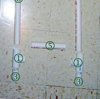
3 Base assembly Materials used in this section: 1 (4) ¾ elbow join 2 (4) ¾ T-join 3 (1) 18 long ¾ pipe 4 (2) 12 long ¾ pipe 5 (2) 6 long ¾ pipe 6 (4) 8½ long ¾ pipe Before After Assemble as pictured, pushing firmly. The 2 T-joins with an open end should face up when the base is placed on the ground. If desired, glue joins to pipes with PVC glue. Page 3 of 10
 ¾ T-join 2 (2) ¾ 45 join 3")
 6 long ¾ pipe 6 (1) 18 long ¾ pipe")

4 Arm Assembly Materials used in this section: 1 (3) ¾ T-join 2 (2) ¾ 45 join 3 (3) 2 long ¾ pipe 4 (1) 23 long ¾ pipe 5 (2) 6 long ¾ pipe 6 (1) 18 long ¾ pipe Assemble as pictured, pushing firmly. If desired, glue joins to pipes with PVC glue. Before After Page 4 of 10
 ¾ /½ T-join* 2 (5) 6 long ½ pipe 3 (5) ½ cap")


5 Windmill Assembly This assembly consist of 3 parts: the yarn holders, the windmill, and the connection Yarn Holders materials: 1 (5) ¾ /½ T-join* 2 (5) 6 long ½ pipe 3 (5) ½ cap *These T-joins are ¾ diameter in the horizontal part and ½ diameter in the vertical part If you re only making a yarn swift that will not be used as a skeiner, you only need to make 4 of these yarn holders instead of 5. Assemble as pictured, pushing firmly. If desired, glue joins to pipes with PVC glue. Connection materials: 1 (1) 2 long ¾ pipe 2 (1) ¾ cap Assemble pipe and cap together, pushing firmly. If desired, glue the join and pipe together with PVC glue. Page 5 of 10


 thumb screws Using a drill, drill a hole into the")

6 Windmill materials: 1 (1) ½ X-join 2 (4) 15 long ½ pipe Assemble X-join to pipes as pictured, pushing firmly. If desired, glue joins to pipes with PVC glue. (This gluing step is optional, but I highly recommend it for the windmill, since mine had a tendency to come apart during high-speed swifting before I glued it together.) Drilling: Now comes the slightly harder part drilling holes! For the Yarn Holders: Materials needed in this section: (5) thumb screws Using a drill, drill a hole into the side of the T-joins. The holes should be sized appropriately for your thumb screws. Insert thumb screw and turn several times around with a wrench until they are loose enough to be comfortable for hand turning. When we did that, we covered up the surface of the thumb screw with a towel so the wrench won t marr the surface. Page 6 of 10


7 For the Windmill and Connection: Materials needed in this section: (1) 4 long ¼ bolt with 1 nut, 4 washers, and a 1 long spacer Using a drill, drill a hole all the way through the cap and the middle of the X-join. The holes should be sized appropriately for your bolt. Washer, Spacer, Washer Put a washer on the bolt, then put the bolt through the windmill. On the other side, put a washer, then the spacer, and then another washer. Put the bolt through the connection. Finally, put a washer and a nut to finish it off. To be safe, we superglued the nut in place. Bolt, then washer Washer, then nut Page 7 of 10

8 To complete the windmill assembly: Materials needed in this section: (4) ½ cap Loosen the thumb screws on the yarn holders just enough so you can slide them onto the windmill. I did one on each arm, with one arm getting an additional yarn holder to function as a handle when I crank it as a skeiner. If you re only going to use it as a swift, just do one yarn holder on each arm. Tighten the screws just enough so that they won t flop around. Finish off each arm of the windmill with a ½ cap. DO NOT glue these down! In fact, try not to push too hard on them so that they d be removable later. When I use this as a swift, I remove the additional yarn holder to give it better weight distribution. The cap has to come off before I can slide the additional arm off. Page 8 of 10


9 Final assembly! Whew! You re almost done! This is the part where you put it all together. Put the base on the floor. Push the arm assembly into the open t-joins in the base. Put the connection of the windmill assembly into the arm assembly. Viola your skeiner/swift is finished! To store flat: When I m not feeling lazy, I will take the windmill, arm, and base assemblies apart into 3 pieces to store them flat. The windmill assembly can be made flat by loosening the thumb screws and turning the arms to the side. To use: Just reassemble and turn the yarn holders back to the correct position. If using it as a skeiner, adjust the yarn holders to the appropriate length and wind by cranking the middle handle. If using it as a swift, remove the additional yarn holder. Adjust the remaining yarn holders to be the appropriate length. Try to make them all about equidistance from the center. The better the weight distribution, the better it spins. (Hint: use some WD-40 on the bolt if it doesn t spin as smoothly as you d like it to. It worked wonders for me). Page 9 of 10

 through the part of the pipe where I want them, then screwed them on.")
10 Optional skeiner yarn guide I added these cup hooks to the base of the skeiner when I was skeining a cone of yarn. These help guide the yarn onto the skeiner so you don t have to. I purchased these cup hooks from Target, but you can probably buy them anywhere. I just drilled a small hole (3/32 ) through the part of the pipe where I want them, then screwed them on. When skeining yarn, I ll just periodically change hooks so it winds on fairly evenly. Page 10 of 10
Electric Skein Winder
 Electric Skein Winder Assembly and Use Package Contents 1 - Triangular Body (w/ motor) 1 - Cross Arm 1 - Left Foot (w/ yarn guide) 1 - Right Foot 1 - Adjustable Finger (w/ yarn clip) 3 - Adjustable Fingers
Coro Character PVC Frame Instructions:
 Coro Character PVC Frame Instructions: In this tutorial we will show you how to make a basic light weight frame for your Coro character. Then we will show you how to add on to your frame to help you either
LOFT DOOR HANGER BARN DOORS & HARDWARE. Hardware Installation Instructions. Page
 LOFT DOOR HANGER Page 1 Specifications 2 7/16" 3/8" 1-1/2 1-3/4 Ø3 3 7/8" 11-1/16 Page 2 Parts and Tools Tools Needed Tape Measure Pencil Drill with 1/8, 1/4 and 3/8 bits, 1 spade bit and Phillips bit
User Instructions Multiline Otter Scoreboard Caddy Assembly
 List of parts: User Instructions Multiline Otter Scoreboard Caddy Assembly Single Caddy Double Caddy 1 1 Base assembly with attached wheels 2 4 1 1 2 4 4 8 10 20 12 Uprights (60 or 74 aluminum extrusion)
Leafy Greens Spinner Construction Manual
 Leafy Greens Spinner Construction Manual University of Houston Conrad N. Hilton College Food Science Lab Materials list: Base and Armature Approximately 8-1 PVC cut into sections o 3-22.5 o 2-7 o 2-4 o
#916 CLASSIC 16 GUN CABINET ASSEMBLY INSTRUCTIONS
 Thank you for purchasing this quality product. A list of PARTS and INSTRUCTIONS is included to assist you. Unpack and identify all parts included on the Parts List and Hardware List. If parts are missing,
The brackets have been tested on the 2017 and 2018 versions of the Spirit Proton pack and also with two separate A.L.I.C.E.
 Introduction Congratulations on purchasing the Spirit Brackets Kit that allows very secure attachment of an A.L.I.C.E. pack frame to your Spirit Halloween Proton Pack. The Spirit Brackets Kit is designed
TABLE OF CONTENTS REQUIRED TOOLS
 TABLE OF CONTENTS SECTION SECTION TITLE PAGE NO. 1 2 3 4 5 Assembling Mounting Structure Installing Bicycle Supports Mounting Rack to Wall Adding Sections Customizing Rack Configuration REQUIRED TOOLS
INSTALLATION INSTRUCTIONS
 INSTALLATION INSTRUCTIONS Furniture Solutions: 68 Shipstation with Storage Shelf Model Numbers: PB001 (D9001, D9010N, D9021, D9030, D9032/D9033, D9098, RC4054) Introduction This document provides the Pitney
SAFETY SHIELD FOR 12, 14 AND 16 WOOD LATHES
 PART O. 1340198(013) 46-896 SAFETY SHIELD FOR 12, 14 AD 16 WOOD LATHES ITRODUCTIO The 46-896 Safety Shield (Fig.1) is an accessory for Delta 12 and 16 wood lathes. The shield can also be retrofitted to
Track Rack. * Track Racks are not lockable
 The Track Rack s unique staggered, sliding hook design creates the greatest parking efficiency while still providing easy access to any particular bike. When adding or removing a bike to the rack, simply
TIRE RACK INSTALLATION INSTRUCTIONS Dodge Sprinter
 Aluminess Products Inc 9402 Wheatlands Ct. #A Santee, CA 92071 619-449-9930 TIRE RACK INSTALLATION INSTRUCTIONS 07-11 Dodge Sprinter Please read before beginning Stainless steel hardware may bind together
6000 Horizontal Router Table Owners Manual Please Read Carefully!
 6 Horizontal Router Table Owners Manual Please Read Carefully! Parts List Please identify and verify that you have all of the hardware & parts shown prior to assembly. The parts described in this box are
BEAST THE. Tube and Pipe Notcher Operating Instructions. Notches In Bends Straight Notches. Angled Notches. Offset Notches
 Copyright (c) 2007 J D SQUARED INC. www.jd2.com THE BEAST Tube and Pipe Notcher Operating Instructions Notches In Bends Straight Notches Angled Notches PATENT PENDING Offset Notches Assembly After unpacking
Metroboard Pulley Replacement Procedure
 Metroboard Pulley Replacement Procedure 1) Remove the two transmission cover screws (1/8 allen driver). Then remove the transmission cover. Note there is a split lock washer and flat washer as well, so
Obtained from Omarshauntedtrail.com
 DaveintheGrave's Halloween Props Animated Crawling Skeleton Build a life-size skeleton torso that realistically crawls across the lawn one arm at a time. 1. Motor Base and Linkage Assembly BASE - I used
43107 Rhino Jerry Can Holder Rhino Jerry Can Holder - Horizontal
 Important: Please read these instructions carefully prior to installation. Check the contents of kit before commencing fitment and report any discrepancies. Clean the alloy tray prior to installation.
18600 Angular Momentum
 18600 Angular Momentum Experiment 1 - Collisions Involving Rotation Setup: Place the kit contents on a laboratory bench or table. Refer to Figure 1, Section A. Tip the angular momentum apparatus base on
Heavy Duty Ceiling Tilt Mount Installation Manual
 HD-CTM-5580 Heavy Duty Ceiling Tilt Mount Installation Manual *This Installation requires a minimum of two people. For your safety: Read the complete instruction manual before starting an installation
INS T A L L A TIO N INS T R U C TIO N S HORSESHOE W/ BAR HANGER
 INS T A L L A TIO N INS T R U C TIO N S HORSESHOE W/ BAR HANGER 6-1/2" 5" 2-7/16" 3-7/16" Ø2-7/8" 4-7/8" 11" 2" 3/16" 1/2" HORSESHOE W/ BAR S P ECIFICATIONS PARTS AND TOOLS Tools Needed Tape Measure Pencil
Hardware and Components:
 Hardware and Components: (A) 5/16 x 2 Hex Bolt (B) 5/16 x 2-1/4 Hex Bolt (C) 5/16 x 2-1/2 Hex Bolt (D) 4X 5/16 x 3/4 Hex Bolt (E) 4X 5/16 x 1-1/4 Hex Bolt (F) 11X 5/16 Flat Washer (G) 12X 5/16 Nylock Nut
High Rise Sit-Stand Desk Converter
 High Rise Sit-Stand Desk Converter Assembly Instructions for Model DC300 Patent Pending PRE-ASSEMBLY Please read all instructions before beginning assembly. We strongly recommend you watch the video at
Project Identity. Assistive Robotic Arm Week 9 March April 4, 2007 Megan Madariaga
 Project Identity Assistive Robotic Arm Week 9 March 28 2007- April 4, 2007 Megan Madariaga Work Completed: On Friday March 30 th we filled out the return sheet for our large base motor then traveled to
**MOUNTING YOUR MONITOR
 FPP72V200 72 FREE STANDING DISPLAY CART Assembly Instructions Hardware List Ref. Qty. Part No. Description AA 4 030-1128 1/4-20 UNC, 1 3/4 Socket Hd Screws BB 1 030-1129 5/8-11 UNC 1 3/4 Socket Hd Screw
Grade 8 Enriched Math Catapult Project 2012 Step by Step Instructions to building a catapult
 Grade 8 Enriched Math Catapult Project 2012 Step by Step Instructions to building a catapult Grade 8 Enriched Math Project INSTRUCTION SHEET FOR CATAPULT Procedures, materials and tools: below is a step-bystep
Classic Roll Tarp. Installation Instructions. Attention Dealers: Please give this owners manual to the customer when the product is delivered.
 Serving the Truck & Trailer Industry Since 1944 Classic Roll Tarp Attention Dealers: Please give this owners manual to the customer when the product is delivered. Call 800-535-9545 www.aeroindustries.com
Drake Off Road Hood Hold Downs Installation Guide
 Installation Time: 30 Minutes Tools Required: Drake Off Road Hood Hold Downs Installation Guide 3/8 drive ratchet 13mm socket 10mm socket (deep-well socket helpful) 13mm wrench (2x) 4mm allen wrench 5mm
TOOL LIST FOR TAILGATE HIDDEN LATCH & LINK ASSY FOR FORD FLARESIDE TRUCKS
 TOOL LIST FOR TAILGATE HIDDEN LATCH & LINK ASSY FOR 53-87 FORD FLARESIDE TRUCKS Vise Grip Clamps C-clamps Sharpie Marker Ball Peen Hammer Center Punch 3/8 or 1/2 Drill 5/32, 7/32, 9/32, and 3/8 Drill Bits
Horizontal Cable Systems
 ALUMINUM RAILING INSTALLATION INSTRUCTIONS v2012 orizontal Cable Systems 1) Check Contents Of Packages: Verify that all parts have arrived and that they match the packing list. 1A) Coastal applications:
Nancy s Knit Knacks LLC 4 Yard Option Upgrade Kit Assembly Instructions and User Manual
 Nancy s Knit Knacks LLC 4 Yard Option Upgrade Kit Assembly Instructions and User Manual Thank you for purchasing our 4 Yard Option (4YO) Upgrade Kit. To install this upgrade you are simply going to assemble
CV1B Sliding Table Installation and Setup Guide
 CV1B Sliding Table Installation and Setup Guide Tech Mark, Inc 7901 Industry Drive North Little Rock, AR 72117 tel (501) 945-9393 fax (501) 945-0312 www.tech-mark.com email: info@tech-mark.com The CV1B
AUTOMATIC ADVANCE MANUAL
 AUTOMATIC ADVANCE MANUAL AVL Looms, Inc. 3851 Morrow Lane, Suite #9 Chico, CA 95928-8305 530 893-4915 530 893-1372 fax # info@avlusa.com www.avlusa.com Copyright 2009 TABLE OF CONTENTS Page # I. Parts.........................
FIRST TEAM SPORTS, INC.
 FIRST TEAM SPORTS, INC. INVADER EZ-CRANK PORTABLE BASKETBALL GOAL ASSEMBLY INSTRUCTIONS Revised - 08/04/10 BILL OF MATERIALS (1) BASE TANK (1) BACKBOARD MOUNT (2) 5/16 X ¾ HEX BOLT (1) LOWER POST (2) SPRING
BABY WOLF LOOM. Assembly Instructions for Knocked-Down Looms
 BABY WOLF LOOM Assembly Instructions for Knocked-Down Looms BEFORE YOU BEGIN Please read through the directions before beginning to assemble your loom. Unpack the loom parts carefully. Do not throw away
The Phoenix. Professional Quilting Frame. Copyright January 1, 2016 Jim M. Bagley, GraceWood, Inc (Reproduction Prohibited) Version 2.
 Version 2.") The Phoenix Professional Quilting Frame Copyright January 1, 2016 Jim M. Bagley, GraceWood, Inc (Reproduction Prohibited) Version 2.1 1 The Phoenix Professional Quilting Frame Parts List Box 1...3 Box
The Phoenix Professional Quilting Frame Copyright January 1, 2016 Jim M. Bagley, GraceWood, Inc (Reproduction Prohibited) Version 2.1 1 The Phoenix Professional Quilting Frame Parts List Box 1...3 Box
Required Tools: Suggested Additional Tools: 1 Cordless Drill with Robertson Bits 1 Ratchet Wrench 1 7/16 or 11mm socket 1 7/16 or 11mm Gear Wrench
 Thank you for your recent purchase of a Cabinets by Hayley garage cabinet system. You are about to experience the best made cabinets that you can purchase. Cabinets by Hayley are designed for beauty and
Hardware and Components:
 Hardware and Components: (A) 4X 5/16 x 1 Carriage Bolt (B) 2X 5/16 x 2-1/4 Carriage Bolt (C) 2X 5/16 x 3-1/4 Hex Bolt (D) 2X 5/16 x 3/4 Hex Bolt (E) 2X 5/16 x 1-1/4 Hex Bolt (F) 5/16 x 2-1/4 Hex Bolt (G)
Kwik-Lock. Installation Instructions. Attention Dealers: Please give this owners manual to the customer when the product is delivered.
 Serving the Truck & Trailer Industry Since 1944 Installation Instructions Attention Dealers: Please give this owners manual to the customer when the product is delivered. Call 800-535-9545 www.aeroindustries.com
ROCKWELL. Two Panel Door. Half X Door. Double X Door. Z Combination Door
 ROCKWELL 4 in 1 DOOR Choose between four door styles with this Door Kit. Our versatile Rockwell Door Kit is very easy to assemble. All materials and hardware needed to assemble any of the four styles are
Heavy-Duty Bypass Track System
 Heavy-Duty Bypass Track System Please Note: This track system must be installed with the screws going into a solid surface such as studs or a header. Due to the spacing of the holes on these Brackets,
VACUSEAL MODEL 200. HOT TUB PRODUCTS 233 Carrington Road Bethany CT
 VACUSEAL MODEL 200 J G F G H L HOT TUB PRODUCTS 233 Carrington Road Bethany CT 06524 860-469-2580 www.vacusealcoverlift.com www.hottubproducts.com Made in USA H K E D C I A P B 10 9 8 7 6 5 4 3 2 1 0 SPAS
This manual will aid in the assembly of the FireBall V90 and FireBall X90. The assembly of both machines will be identical, unless specified.
 This manual will aid in the assembly of the FireBall V90 and FireBall X90. The assembly of both machines will be identical, unless specified. Step #1 Lay all parts out to verify quantities. (2) 2 x 25-1/4
Castle Frame Assembly Table AT-8. Diagnostics Manual. Castle, Inc. Petaluma, CA
 Castle Frame Assembly Table AT-8 Diagnostics Manual Castle, Inc. Petaluma, CA 800-282-8338 Solutions Index Adjusting the Tabletop.. 8.01 Adjusting the Fence... 8.02 Aligning the Arm... 8.10 Adjusting Bracket..
ROCKWELL 4-IN-1 DOOR. Two Panel Door. Half X Door. Z Combination Door. Double X Door
 ROCKWE 4-IN-1 DOOR Two Panel Door Half X Door Double X Door Z Combination Door Choose between four door styles with this Door Kit. Our versatile Rockwell Door Kit is very easy to assemble. All materials
Congratulations! You are now on your way to enriching your life with!
 C) Using the base point as your reference, measure up 8-1/32 and mark a horizontal line. Measure in from the edge of the door the distance of your backset and mark where the two lines cross. This will
INSTALLING YOUR NEW SPRING LIFT ARM KIT
 INSTALLING YOUR NEW SPRING LIFT ARM KIT 1. Measure the distance that the roof is to be raised. [If your lift system is completely non-functional, you will need to calculate or estimate this distance as
Classic Roll Tarp. Installation Instructions. Attention Dealers: Please give this owners manual to the customer when the product is delivered.
 Serving the Truck & Trailer Industry Since 1944 Classic Roll Tarp Attention Dealers: Please give this owners manual to the customer when the product is delivered. Call 800-535-9545 www.aeroindustries.com
PFW Installation Guide Installationsanleitung, Guía de Instalacíon, Guida de Installazione, Guide d Installation, Installatie gids
 Maximum Flat Panel Weight: 100 lb. / 45.35 kg. Included Components Wall Mount (Qty 1) Extension Bracket (Qty 1 Pair) Bracket (Qty 1 Pair) 5/16 Flat Washers (Qty 4) Universal Spacers (Qty 8) M5 Allen Driver
A Metal Polishing Jig. By Norm Berls
 A Metal Polishing Jig By Norm Berls Why make a metal polishing jig Objective: polish small steel parts to a mirror-like finish. Silicon Carbide abrasive paper works well under certain conditions. Paper
Assembly Instructions
 page 1 Serious personal-injury to the operator or bystanders, as well as damage to equipment or property, can occur, if all safety and assembly instructions, provided with this product, are not followed.
WOLF PUP LOOM TM & WOLF PUP LT LOOM TM
 WOLF PUP LOOM TM & WOLF PUP LT LOOM TM Assembly Instructions FL3000 FL3006 FL3009 WOLF PUP WOLF PUP LT Find out more at schachtspindle.com Schacht Spindle Company 6101 Ben Place Boulder, CO 80301 p. 303.442.3212
Wooden Frame Type Instruction Manual
 Wooden Frame TypeInstruction Manual Thank you for selecting our product. Before starting installation, please read this manual thoroughly to ensure correct installation. Please keep this manual at hand
C PART LIST HARDWARE LIST. Kitchen Cart IMPORTANT NOTE
 88 9200 006C Kitchen Cart IMPORTANT NOTE Carefully remove all the parts from the carton and put them individually on a soft cloth to prevent scratches or other damages occuring to the parts. We have taken
SINGLE TRACK BYPASS (patent pending) barn door hardware
 barn door hardware") SINGLE TRACK BYPASS (patent pending) barn door hardware Installation Manual What is included in your kit: Part number Part name Quantity 1 Inner door hanger 2 2 Outer door hanger 2 3 5/16 x 1.5 lag bolts
SINGLE TRACK BYPASS (patent pending) barn door hardware Installation Manual What is included in your kit: Part number Part name Quantity 1 Inner door hanger 2 2 Outer door hanger 2 3 5/16 x 1.5 lag bolts
Calf-Tel Pen System Assembly Instructions
 Calf-Tel Pen System Assembly Instructions (Instructions work for 4, 6, and the 7 Pen Systems) 1 ASSEMBLY OF PEN FRONT AND WALLS START THE ASSEMBLY BY LINING UP THE TWO UNI-DIRECTIONAL ARROWS IN THE TOP,
PFW 6875 Installation Guide Installationsanleitung, Guía de Instalacíon, Guida de Installazione, Guide d Installation, Installatie gids
 Maximum Flat Panel Weight: 160 lb. / 72.57 kg. Included Components Wall Mount (Qty 1) Extension Brackets (Qty 2) Bracket (Qty 1 Pair) 5/16 Flat Washers (Qty 4) Universal Spacers (Qty 8) M5 Allen Driver
Katerack Wagon Shelving System
 Ford Transit Connect Assembly Installation Instructions Sheet 1 of 14 BEFORE YOU START! IMPORTANT INSTALLATION STEPS ARE DENOTED USING A STOP SIGN. THESE STEPS MUST BE PERFORMED IN THE SPECIFIED ORDER
MITCHELL WREATH RINGS NO-HAMMER ASSEMBLY INSTRUCTIONS
 MITCHELL WREATH RINGS NO-HAMMER ASSEMBLY INSTRUCTIONS METAL STAND WITH WOOD STAND WITH PAGE 2 OF 10 MASTER PARTS LIST HEAD ASSEMBLY LINKAGE ASSEMBLY HOOK LEVER ASSEMBLY FOOT PEDAL ASSEMBLY ALL FASTENERS
Parts List. U-DS92ST Ashley Creative Center With Padded Stool Assembly Instructions. [15] - Plastic Thick Washer (2 - pieces) [22] - Wrench (1 piece)
![Parts List. U-DS92ST Ashley Creative Center With Padded Stool Assembly Instructions. [15] - Plastic Thick Washer (2 - pieces) [22] - Wrench (1 piece)](/thumbs/82/86598067.jpg "Parts List. U-DS92ST Ashley Creative Center With Padded Stool Assembly Instructions. [15] - Plastic Thick Washer (2 - pieces) [22] - Wrench (1 piece)") [1] - 23.5 x 35.5 Top [8] - Drawer Support Rods Parts List [15] - Plastic Thick Washer (2 - pieces) [22] - Wrench [2] - Upper Base left End (1 pieces) [9] - Media Supports (1 pieces) [16] - loor Guides
[1] - 23.5 x 35.5 Top [8] - Drawer Support Rods Parts List [15] - Plastic Thick Washer (2 - pieces) [22] - Wrench [2] - Upper Base left End (1 pieces) [9] - Media Supports (1 pieces) [16] - loor Guides
WAREHOUSE HANGER INSTALLATION INSTRUCTIONS R H INS T A L L A TIO N INS T R U C TIO N S
 INS T A L L A TIO N INS T R U C TIO N S WAREHOUSE HANGER NOTE: Due to the size and weight of the Warehouse Hanger it is recommended that this Hanger be installed on 3 4 or wider doors. 10.11.2016 2-3/16"
How to build a hockey stick bench
 How to build a hockey stick bench The hockey stick bench is a great piece of fully functional furniture that doesn t require a lot of sticks. Composite sticks are really strong, so even if you space them
00108/00110 INSTRUCTION MANUAL
 00108/00110 INSTRUCTION MANUAL Removable and Adjustable Mudflap System IMPORTANT! Exhaust Systems Note: Any modifications to the factory installed exhaust system may void your manufacturer s warranty.
Assembly Instructions for model: VMPR1
 Assembly Instructions for model: VMPR1 Congratulations on your purchase! The VMPR1 ceiling mount provides a unique, simplified method of ceiling mounting inverted LCD/DLP projectors. Its low profile design
96 (Standard Length)
") Setbacks 96 (Standard Length) Bike Files may be lined up end to end to fill the available space. A 36 aisle should be left between the ends of bikes in racks facing one another. 36 aisle 50 Installation
Setbacks 96 (Standard Length) Bike Files may be lined up end to end to fill the available space. A 36 aisle should be left between the ends of bikes in racks facing one another. 36 aisle 50 Installation
INSTALLATION INSTRUCTIONS INS T A L L A TIO N INS T R U C TIO N S ROD IRON SCROLL HANGER R H
 INS T A L L A TIO N INS T R U C TIO N S ROD IRON SCROLL HANGER 10.5.2016 2-1- 3/16" 11/16" 8" 8 O 2-7/8 Ø2-7/8" 3-1/2 3-1/2" 12-9/16 12-9/16" PLEASE NOTE: These instructions are specific to a particular
Playground Assembly Instructions
 Before You Begin Playground Assembly Instructions Locate the playground set on firm, level ground. Assemble the playground on or close to its permanent location Two people are recommended to assemble the
Kai Installation Instructions
 Kai Installation Instructions Before Beginning Installation Read through the entire instruction thoroughly A minimum of 2 people are required for this assembly These instructions reflect typical assemblies;
MM540 Installation Instructions IMPORTANT SAFETY INSTRUCTIONS - SAVE THESE INSTRUCTIONS
 MM50 Installation Instructions IMPORTANT SAFETY INSTRUCTIONS - SAVE THESE INSTRUCTIONS Please read this entire manual before you begin. Do not unpack any contents until you verify all requirements on PAGE.
19 to 39 TV WALL MOUNT - FULL MOTION
 19 to 39 TV WALL MOUNT - FULL MOTION RF-HTVMMAB For wood-stud and concrete wall installations Safety information and specifications...2 Tools needed...2 Package contents...3 Installation instructions...5
Installation Instructions
 Installation Instructions Walk-in Shower Screen with 180 o Return Panel (700 + 350mm & 900 + 350mm) Installation Instructions Parts supplied A B C D Wall Channel (x1) Wall fixing screw (x6) Return Straight
Rough Country JK Modular Winch Mount Bumper With Light End Caps
 Rough Country JK Modular Winch Mount Bumper With Light End Caps Note: These instructions involve cutting parts of your vehicle. Please read all instructions prior to starting. Note: This installation also
Greenhouse Assembly Instructions
 Greenhouse Assembly Instructions Our Help Line provides support and advice to customers of Summer Garden Buildings after ordering. For advice before you buy you can phone us free 7 days a week on 0800
MM750 Installation Instructions
 MM750 Installation Instructions IMPORTANT SAFETY INSTRUCTIONS - SAVE THESE INSTRUCTIONS Please read this entire manual before you begin. Do not unpack any contents until you verify all requirements on
DeRosa DRM-516 (5-PIECE 16 ) Drum Kit ASSEMBLY INSTRUCTIONS
 Drum Kit ASSEMBLY INSTRUCTIONS") DeRosa DRM-516 (5-PIECE 16 ) Drum Kit ASSEMBLY INSTRUCTIONS Along with reading this guide, we also recommend that you watch the DeRosa 516 Drum Kit Assembly video on the Austin Bazaar Product FAQ page
DeRosa DRM-516 (5-PIECE 16 ) Drum Kit ASSEMBLY INSTRUCTIONS Along with reading this guide, we also recommend that you watch the DeRosa 516 Drum Kit Assembly video on the Austin Bazaar Product FAQ page
INSTALLATION INSTRUCTIONS INS T A L L A TIO N INS T R U C TIO N S THE MAVERICK HANGER R H
 INS T A L L A TIO N INS T R U C TIO N S THE MAVERICK HANGER 10.6.2016 PARTS INSTALLATION SPECIFICATIONS AND TOOLS INSTRUCTIONS 2-1/4" 2-7/8 11-3/8" 1/4" 2-1/8 PARTS INSTALLATION AND INSTRUCTIONS TOOLS
PRE-ENGINEERED HORSE STALL SYSTEMS SDFD SLIDING DOOR c/w FOLD-DOWN GRILL. & Assembly. Installation Instructions
 PRE-ENGINEERED HORSE STALL SYSTEMS 4800 SDFD SLIDING DOOR c/w FOLD-DOWN GRILL & Assembly Installation Instructions 4800 SDFD Sliding Door c/w Fold-Down Grill Components - 1 3 /4" x 2" x 88" channels (2)
VERSION 1.0 JANUARY 5, 2013 R2-ATL MOTOR MOUNT KIT ASSEMBLY GUIDE ASTROMECH DRIVE SYSTEM
 VERSION 1.0 JANUARY 5, 2013 R2-ATL MOTOR MOUNT KIT ASSEMBLY GUIDE ASTROMECH DRIVE SYSTEM R2-ATL MOTOR MOUNT KIT PURPOSE The R2-ATL motor mount is designed for use in Astromech s Droids up to 300 pounds.
For all Davis weather consoles including Vantage Pro2,
 USR MANUAL Universal Shelter For all Davis weather consoles including Vantage Pro2, Vantage Pro2 Plus R, Vantage Vue, nvoy 8X, and Weather nvoy Product Number 6618 R Davis Instruments, 3465 Diablo Avenue,
END FRAMES. End frames built using pressure treated 2x4 (1 1/2" x 3 1/2") 36" 34" 7/16" pilot hole. 5 1/2" x 1/2" lag bolt 8" wheel 23"
 36 34 7/16 pilot hole. 5 1/2 x 1/2 lag bolt 8 wheel 23") END FRAMES End frames built using pressure treated 2x4 (1 1/2" x 3 1/2") 23" 17 1/2" (B) (B) Measure from the bottom of your stone to 1" below the lip to get your measurement. 17 1/2"(B) 36" 34" 1/2" flat
END FRAMES End frames built using pressure treated 2x4 (1 1/2" x 3 1/2") 23" 17 1/2" (B) (B) Measure from the bottom of your stone to 1" below the lip to get your measurement. 17 1/2"(B) 36" 34" 1/2" flat
SIGNATURE FRONT BUMPER INSTALL
 SIGNATURE FRONT BUMPER INSTALL JL **PLEASE READ THROUGH THE INSTRUCTIONS BEFORE BEGINNING ANY PART OF THE INSTALLATION PROCESS** 1. You can now remove the trim strip (2 vertical clips, 4 horizontal, 2
SAM. Model: STV-C65 LCD Mobile Visualized Stand Instruction Manual. Weight Capacity: 1251bs / 56.7kg Suits LCD Flat Panel Display: 42"-55" Page 20
 SAM Model: STV-C65 LCD Mobile Visualized Stand Instruction Manual Weight Capacity: 1251bs / 56.7kg Suits LCD Flat Panel Display: 42"-55" 20 Step 6 LCD Mobile Lift Stand Model: STV-C65 Cable management
S10C. Instructions. Version S10C-V1c
 S10C Instructions Version S10C-V1c To celebrate our fortieth anniversary, we have transformed the spinning wheel it all started with: the S10. The new S10 Concept spinning wheel makes it possible to customize
6625 WEST WILSHIRE BLVD. OKLAHOMA CITY, OK (405) FAX (405)
 FAX (405)") INSTALLATION INSTRUCTIONS FOR THE TAILGATE WITH LATCH AND LINK ASSEMBLY 76-87 FORD SHORT & 53-87 FORD LONG FLARESIDES 1. Assemble the bed and make sure the box is square. Measure the distance between the
INSTALLATION INSTRUCTIONS FOR THE TAILGATE WITH LATCH AND LINK ASSEMBLY 76-87 FORD SHORT & 53-87 FORD LONG FLARESIDES 1. Assemble the bed and make sure the box is square. Measure the distance between the
HIGH RISE Portable Restroom Assembly Instructions
 HIGH RISE Portable Restroom Assembly Instructions 2530 Xenium Lane North, Minneapolis, MN 55441 Telephone: 763-553-1900 / Fax: 763-553-1905 800-328-3332/ www.satelliteindustries.com PN 20930 REV C 8/16
Side Katerack Installation Instructions
 Side Katerack Installation Instructions Ram ProMaster City 2015+ Frame Kit Part #: CRC 28-1000-001 V1.0.12.06.18 IMPORTANT INSTALLATION STEPS ARE DENOTED USING A STOP SIGN. THESE STEPS MUST BE PERFORMED
Grand Slam 270 Installation Instructions
 Grand Slam 270 Installation Instructions TACO Metals Inc., info@tacomarine.com TACOmarine.com INSTALLATION OF YOUR NEW GRAND SLAM 270 OUTRIGGER BASE ON A T-TOP (CANVAS TOP) When installing the Grand Slam
ASAP Sr. A Strap and Pole. Magic Christmas. Single Stage. Walter Monkhouse. Alexandria, La. Version 1.2.
 ASAP Sr Single Stage A Strap and Pole Version 1.2 Walter Monkhouse Walter@MagicChristmas.org Magic Christmas Alexandria, La. Description The ASAP Sr, single stage, has the same concept as the ASAP Jr.
Real Life Ninja Complete Starter Pack (14ft. Warped Wall) Assembly Instructions
 Assembly Instructions") MATERIALS: 3 - Main Sections (Only 2 Sections for 10 ) 8 3 deck screws for joining sections inside of 2 Rock Wall Panels (with pre-installed t-nuts. Top panel comes with ladder mounting block preinstalled.)
MATERIALS: 3 - Main Sections (Only 2 Sections for 10 ) 8 3 deck screws for joining sections inside of 2 Rock Wall Panels (with pre-installed t-nuts. Top panel comes with ladder mounting block preinstalled.)
Installation Instructions
 Articulating Dual Monitor Mount Stand Installation Instructions UNPACKING Carefully open the carton, remove contents, and place them on a protected surface to avoid damage. Check the parts and the Supplied
Horizontal Cable Systems
 ALUMINUM RAILING INSTALLATION INSTRUCTIONS Horizontal Cable Systems 1) Check Contents Of Packages: Verify that all parts have arrived and that they match the packing list. 1A) Coastal applications: Confirm
Desk/Wall-Mount Rack
 Desk/Wall-Mount Rack Patent(s) Pending Installation Instructions Post P/N: 119-1752 119-1781 119-1782 119-4014 Frame P/N: 119-1591 119-1754 119-1755 Kit Contents (2) Frames (4) Posts Assembly Hardware
Medium HoneyBadger Chase Rack Installation Instructions
 PREPARATION Medium HoneyBadger Chase Rack Installation Instructions 1. Disconnect the negative terminal on the battery. Park the vehicle on level ground and set the emergency brake. 2. We recommend reading
6 Cub Pack Drawer IMPORTANT WARNING! INSTALL TIME: 45 mins SSAM014
 6 Cub Pack Drawer SSAM014 INSTALL TIME: 45 mins IMPORTANT WARNING! IT IS CRITICAL THAT ALL FRONT RUNNER PRODUCTS BE PROPERLY AND SECURELY ASSEMBLED AND ATTACHED TO YOUR VEHICLE. IMPROPER ATTACHMENT COULD
7902 Dado Jig. Owners Manual Please Read Carefully! Hardware List: 7902 Parts List:
 7902 Dado Jig Owners Manual Please Read Carefully! 7902 Dado Jig Hardware List: Identify and verify that you have all of the hardware shown below prior to assembly. Please read the instructions at least
M10 x 75mm Sockethead Cap Screws. 5mm Fender Washer (12) Included - (8) Required. #10 x 2.5" PH Wood Screws. (30) Included - (24) Required
 Included - (8) Required. #10 x 2.5 PH Wood Screws. (30) Included - (24) Required") Door System Unit - Hardware Tools Included: (2) 2mm Allen Wrenches, (2) 3mm Allen Wrenches, (2) 4mm Allen Wrenches, (2) 6mm Allen Wrenches, and (1) 8mm T-Handle Allen Wrench Tools Required: Phillips Screwdriver,
Door System Unit - Hardware Tools Included: (2) 2mm Allen Wrenches, (2) 3mm Allen Wrenches, (2) 4mm Allen Wrenches, (2) 6mm Allen Wrenches, and (1) 8mm T-Handle Allen Wrench Tools Required: Phillips Screwdriver,
Lucky Dog Sports Club.com 300 S. Central Blvd., Jupiter, FL
 Lucky Dog Sports Club.com 300 S. Central Blvd., Jupiter, FL 33458 561-427-6700 Construction of a Bar Jump or Hurdle By Roger at www.instantagility.com This is the most basic of agility obstacles. It s
U.S. Rack, Inc Falcon Drive, Madera, CA APR17 INSTALLATION AND USE INSTRUCTIONS for SIDE-MOUNT LADDER RACK
 U.S. Rack, Inc. 2850 Falcon Drive, Madera, CA 93637 15APR17 INSTALLATION AND USE INSTRUCTIONS for SIDE-MOUNT LADDER RACK WARNING: Do NOT attempt to install or use this rack without following all instructions.
Shetland Stalls Installation Instructions
 Shetland Stalls Installation Instructions RAMM Horse Fencing and Stalls 13150 Airport Hwy. Swanton, OH 43558-9615 1-800-434-8456 Rev. 1/9/18 Before you start Kit can accommodate up to 12 wide stall front
Depending on the size you ordered you will have either 5 Foot sections which will build the 10 Foot frame or 6 Foot sections which will build the 12
 XL Quilting Frame 1 Depending on the size you ordered you will have either 5 Foot sections which will build the 10 Foot frame or 6 Foot sections which will build the 12 Foot frame Printed 2 June 2014 Updated
Fortress Fe Posts must always be secured to the deck framing. Fortress Fe Posts should never be attached to only the deck boards.
 Installation Instructions for Fortress Horizontal Cable Panel System with UB-05 Brackets and Fe Posts It is the responsibility of the installer to meet all code and safety requirements, and to obtain all