Operating Manual. Original Instructions. D439848XA vers. 4
|
|
|
- Rosaline Golden
- 6 years ago
- Views:
Transcription


1 Original Instructions D439848XA vers. 4 EN
2 (c) 2012 SILCA S.p.a. Vittorio Veneto This manual has been drawn up by SILCA S.p.a. All rights reserved. No part of this publication can be reproduced or circulated by any means whatsoever (photocopies, microfilm or other) without the consent of SILCA S.p.a. Edition: June 2012 Printed at Vittorio Veneto by SILCA S.p.a. Via Podgora, 20 (Z.I.) VITTORIO VENETO (TV) Italy The Manufacturer declines any responsibility for possible inaccuracies in this document due to printing or transcription errors. The Manufacturer reserves the right to alter the information without prior notice, except when they affect safety. This document or any of its parts cannot be copied, altered or reproduced without written authorization from the Manufacturer. Keep the manual and look after it for the entire life cycle of the machine. The information has been drawn up by the manufacturer in his own language (Italian) to provide users with the necessary indications to use the key-cutting machine independently, economically and safely. IMPORTANT NOTE: in compliance with current regulations relating to industrial property, we hereby state that the trade-marks or trade names mentioned in our documentation are the exclusive property of authorized manufacturers of locks and users. Said trade-marks or trade names are nominated only for the purposes of information so that any lock for which our keys are made can be rapidly identified.
3 INDICE USE OF THE MANUAL... 1 GLOSSARY SYMBOLS-TERMINOLOGY... 2 GENERAL WARNINGS MACHINE DESCRIPTION WORKING PARTS - PRO WORKING PARTS - EVO ACCESSORIES PROVIDED Technical data ELECTRIC DIAGRAM HANDLING Packing Transport Unpacking Handling the machine MACHINE INSTALLATION AND PREPARATION Checking for damage Environmental conditions Positioning Safety devices Work station description Starting the key-cutting machine Starting the motor Cutter motor on warning light Led lamp (matrix pro version) Led lamp (matrix evo version) MACHINE CALIBRATION AND REGULATION Fitting and removing tools Micrometer gauge Calibration / tool alignment Tracer point spring Carriage spring for laser keys Clamps The clamp unit has several seats dedicated to the positioning of different types of keys: CUTTING Fitting keys Key stop Cutting dimple keys Back cuts Inclined cuts Cutting laser type keys Cutting laser keys with narrow stems Cutting fichet type keys (h profile)...30
4 9.6 Cutting tubular keys (MATRIX PRO version) MAINTENANCE Tightening and replacing the belt Removing the upper front unit Replacing the rollbar Replacing the transparent safety shield Replacing the lamp Adjusting/replacing the vertical carriage spring Checking and replacing fuses Replacing the calibration key pad electronic circuit board Replacing the condenser Replacing the motor Replacing the transformer Replacing switches: master and motor on Aligning/calibrating the clamp Control alignment left-hand stationary jaws Control alignment right-hand stationary jaws Replacing the jaws Replacing the left-hand stationary jaws Replacing right-hand stationary jaws Replacing left-hand clamp mobile jaw Replacing right-hand mobile clamp jaw DECOMMISSIONING AFTER-SALES SERVICE How to apply for after-sales service...45
5 USE OF THE MANUAL This manual has been drawn up by the Manufacturer and is an integral part of the machine literature. The manual gives information it is obligatory for the operator to know and which makes it possible to use the machine safely. User s Manual This user s manual is provided because it is essential for proper use and maintenance of the machine. The manual must be kept carefully throughout the life of the machine, including the decommissioning stage. Keep in a dry place close to the machine where it is always to hand for the operator. IT IS OBLIGATORY to read the manual carefully before using the machine. Readers characteristics This manual must be read and its contents acquired by those who will use it. Manufacturer s ID MATRIX has an ID plate located on the back of the machine, showing the serial number. (*) See Ch. 11 DECOMMISSIONING. Fig. 1 How to apply for after-sales service Silca provides purchasers of MATRIX with After-Sales Service. For the total safety of the operator and machine, any operation not described in the manual must be carried out by the manufacturer or in the special Service Centres recommended by Silca. At the end of the manual there is a list of manufacturers and authorized Service Centre addresses. The warranty card attached to the machine covers free repairs or replacement of faulty parts for 24 months from the date of purchase*. All operations must be agreed by the user with Silca or the Service Centre. * Damage caused by negligence or wrong use of the machine by the user will null the warranty. Copyright Silca

6 GLOSSARY SYMBOLS-TERMINOLOGY To facilitate reading, a glossary is given below of commonly used symbols and terms connected to keys and the key-cutting machine. These symbols and terms will be used in the manual with reference to this page, but we advise reading the list before the rest of the manual. GLOSSARY Tools Clamp unit Vertical carriage Clamp carriage Safety shield Front Hole cutters and Tracer Points clamp set: pull-out tilting clamp unit (right and left hand) for positioning keys spindle unit (tracer point and cutter) with relative support (Z axis) clamp support perpendicular carriages (X, Y axes) transparent shield to prevent swarf scattering and (partially) protect the operator vertical carriage cover dimple cut on the stem or back of the key TERMINOLOGY For those inexperienced in the subject of keys and key cutting, below is an illustration of the most frequently used terms: 1) Head 3) Stop 5) Tip 7) Cuts 2) Neck 4) Stem 6) Back 8) Diameter Fig. 2 (*) PRO only 2 Copyright Silca 2012


 place the adhesive label in the way illustrated. Fig. 3 Fig.")

7 GRAPHICS IN THE USER S MANUAL Pay attention Obligation to read the manual Position of clamp carriage to the left Position of clamp carriage to the right Activation of tracer point spring Deactivation of tracer point spring GRAPHICS ON THE MATRIX KEY-CUTTING MACHINE Obligatory use of safety goggles Cutter release - PRO only - Tracer point spring ON Tracer point spring OFF Adhesive labels Mass - RPM - Fusibles Adhesive label DANGEROUS MOBILE PARTS (cap.4) place the adhesive label in the way illustrated. Fig. 3 Fig. 4 Tool alignment (green) Calibration control ON switch Lamp switch Tracer point-key contact Cutter-key contact Blue LED for machine live Fig. 5 Copyright Silca

8 GENERAL WARNINGS MATRIX is designed to the principles of European Standards (CE). Right from the design stage solutions have been adopted to eliminate hazards for the operator in all the stages of use: handling, regulation, use and maintenance. The materials used in manufacture and the components employed in using MATRIX are not dangerous and ensure that the machine complies to current standards. Silca S.p.A. has also experimented and applied numerous technical solutions that allow the key-cutting machine to optimize the quality of the cut keys. To guarantee maintaining these results over time, please follow the instructions below: Observe the procedures described in this manual; Always use Original Silca Tools as they are designed to make the best of MATRIX and provide quality keycutting; Use Silca key blanks, made with top quality materials; Have the key-cutting machine checked periodically by an authorized Silca After-Sales Service Centre (list at the end of this manual); always use Silca Original Spare Parts. Beware of imitations! NORMAL USE MATRIX is a key-cutting machine and must be installed and used according to the rules and specifications established by the manufacturer. Any other use different from that indicated in this manual will cause the forfeiture of all customers rights to make claims on Silca S.p.A. and may be an unknown source of hazard for the operator or third parties. ATTENTION: Negligent use or failure by the operator to observe the instructions in this manual are not covered by the warranty and the manufacturer declines any responsibility in such cases. RESIDUAL RISKS On the key-cutting machine there is a residual risk of injury in the cutter spindle area (cutter rotating) if the vertical axis for laser cuts is blocked. Furthermore, the MATRIX key-cutting machine has residual risks when gaining access to parts in motion (not fully protected) and the risk of chippings flying into the air during the key copying process. These residual risks in the product are reported in special warnings ( ATTENTION MOVING PART HAZARD ) and involve the obligatory use of personal protective devices (GOGGLES). Fig. 6 SAFETY REGULATIONS Always disconnect the machine when it is not in use or when performing maintenance operations. Check the electrical wiring periodically; replace any wires that show signs of wear. Always work with dry hands free of grease or oil. Never pull hard on the power lead and make sure it does not come into contract with oil, sharp objects or heat. Never remove the earth wire from the plug. Make sure the earth wire connection is sound. Do not use the machine in dangerous environments (wet or damp). All visitors, especially children, must stay at a safe distance from the machine and must never come into contact with the electric wiring. 4 Copyright Silca 2012

 KEYS WITH DIMPLE CUTS KEYS WITH LASER TYPE CUTS LASER KEYS WITH A NARROW STEM")

9 1 MACHINE DESCRIPTION The MATRIX key-cutting machine gives excellent technical performance of great precision. The standard clamp on MATRIX is used to cut the following types of keys: keys with flat or inclined dimple cuts keys with laser type cuts laser keys with a narrow stem (Mercedes) Fichet type keys (H profile) (see note) tubular keys ( PRO only) KEYS WITH DIMPLE CUTS KEYS WITH LASER TYPE CUTS LASER KEYS WITH A NARROW STEM (MERCEDES) FICHET type KEYS (H profile) TUBULAR KEYS with M adapter STANDARD on vers.120v OPTIONAL on vers.230v with F adapter STANDARD on vers.230v OPTIONAL on vers.120v Ø min. 4 mm Ø max.12 mm STANDARD on PRO only Copyright Silca
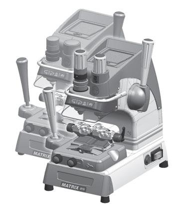
10 2 WORKING PARTS - PRO Fig. 7 A - clamp carriage (X-Y axes) A1- clamp locking lever B - left-hand tilting clamp B1- right-hand tilting clamp C - clamp carriage lever (X-Y axes) D - vertical carriage lever (Z axis) D1- lever release and motor start button E - left-hand clamp knob E1- right-hand clamp knob F - cutter G - transparent safety shield H - clamp carriage locking knob I - clamp tilt locking lever J - lamp K - calibration unit key pad M - tracer point locking knob M1- cutter locking knob N - tracer point spring cam O - carriage spring knob P - ON/OFF switch Q- motor ON switch R - rollbar S - tool box T - tracer point V - tracer point regulation micrometric ring W- motor ON warning light Z - power socket 6 Copyright Silca 2012
 A1- clamp locking lever B - left-hand tilting clamp B1- right-hand tilting clamp C - clamp carriage lever (X-Y axes) D - vertical carriage lever (Z axis) D1- lever")
11 3 WORKING PARTS - EVO Fig. 8 A - clamp carriage (X-Y axes) A1- clamp locking lever B - left-hand tilting clamp B1- right-hand tilting clamp C - clamp carriage lever (X-Y axes) D - vertical carriage lever (Z axis) D1- lever release and motor ON button E - left-hand clamp knob E1- right-hand clamp knob F - cutter G - transparent safety shield H - clamp carriage locking knob I - clamp tilt locking lever J - lamp K - calibration unit key pad N - tracer point spring cam O - carriage spring knob P - ON/OFF switch Q - motor ON switch R - rollbar S - tool box T - tracer point V - tracer point regulation micrometric ring W - motor ON warning light Z - power socket Copyright Silca
12 4 ACCESSORIES PROVIDED MATRIX comes with a series of accessories for use and maintenance (tools, hex wrenches, fuses, etc.) provided in a special holder: FICHET adapter F D910534ZR (STANDARD on vers.230v) MERCEDES adapter M D910533ZR (STANDARD on vers.120v) F1 cutter fuse 2 pcs 2,5 Amp - rapid (230V) 6,3 Amp - rapid (120V/100V) T1 tracer point 2.5 mm hex wrench F22 cutter Steel bar T22 tracer point Calibration pins fuse 1 pc 500 ma - rapid Adhesive label DANGEROUS MOBILE PARTS 4.1 TECHNICAL DATA Power supply: Cutter motor: Cutters: Tool speed: Movements: Clamps: Runs: Dimensions: Illumination: 230V-50/60Hz - 0,75 Amp Watt 100V/120V - 50/60Hz - 2,3 Amp Watt single phase 1 speed motor 230V - 50/60 Hz Super speed steel 6000 rpm (for cutters in super speed steel) on 3 axes by ball guides tilting with interchangeable plates X axis: 40 mm Y axis: 50 mm Z axis: 30 mm width: 310 mm (maximum lever operating space 400 mm) depth: 400 mm height: 470 mm LED lamp Mass: Kg. 24,6 Noise rating: Lp (A) = 70,5 db (A) brass dimple keys Lp (A) = 75,9 db(a) brass keys with laser cuts Lp (A) = 76,6 db(a) steel keys with laser cuts 8 Copyright Silca 2012
13 5 ELECTRIC DIAGRAM Fig. 9 1) Fuses: 2,5 Amp (230V) - 6,3 Amp (100V/120V) 2) Safety switch 3) Terminal board 4) Motor ON/OFF switch 5) Motor 6,3mF (230V) - 14 mf(100v/120v) 6) Motor warning light (LED) 7) Motor safety microswitch 8) Transformer 9) LED circuit 10) LED lamp 11) Tracer point contact 12) Cutter contact 13) Antenna (not on EVO) 14) Fuse 500 ma - rapid Copyright Silca

14 6 HANDLING The MATRIX key-cutting machine is easy to handle and there are no special hazards involved in moving it. The packed machine can by carried manually by one person. 6.1 Packing The packing for the MATRIX key-cutting machine ensures safe handling of the machine and all its components. Packing comprises expanded plastic material wrapped around the machine. The robust cardboard box in which it is placed and the nylon wrapping protect the machine even when stored for a long period. Fig. 10 Keep dry Handle with care Up 6.2 Transport The symbols on the outside of the cardboard box give indications for transport. ATTENTION: keep the packing for future machine transfers. 6.3 Unpacking To remove the machine from its packing: 1) Cut the strapping with scissors and remove. 2) Open the box carefully without damaging it. 3) Free the machine from the protective shells. 4) Check the contents of the packing, comprising: - MATRIX key-cutting machine. - Documentation comprising: user s manual, spare parts sheet, specialist guide and warranty. - Power lead. - Tool holder. 6.4 Handling the machine Once removed from its packing place MATRIX directly on the work bench; one person can easily perform this operation. ATTENTION: lift the machine by holding onto the base. Never lift the machine by gripping the clamps, levers or other parts. 10 Copyright Silca 2012

15 7 MACHINE INSTALLATION AND PREPARATION Installation is the customer s task and does not require any special skills. The key-cutting machine is supplied ready for use and does not need calibration except for the tools to be used; however, the operator is required to make certain checks and prepare the machine for use. 7.1 CHECKING FOR DAMAGE MATRIX is a solid compact machine and will not break if handling, unpacking and installation are carried out to the instructions in this manual. However, it is good practice to check that the machine has not been damaged. 7.2 ENVIRONMENTAL CONDITIONS To make the most of the key-cutting machine, bear in mind the following environmental parameters: it is advisable for the area to be dry with good air circulation. The optimum environmental conditions for machine operation are: - temperature 10 C to 40 C; - relative humidity: approx. 60%. 7.3 POSITIONING 1) Place the key-cutting machine on a solid horizontal work bench suitable for the weight of the machine (24,6 Kg). The work bench should be approximately cm high to facilitate access to the working parts. We recommend leaving at least 30 cm clearance behind and around the machine to ensure good ventilation and facilitate handling (Fig. 11). 2) Make sure machine voltage is suitable for the mains supply and that the latter is earthed with a differential switch. 3) Connect the power lead to the machine. Fig SAFETY DEVICES ON/OFF master switch (P) The master switch (P) is electromagnetic and turns the machine off automatically when power fails. When power returns the switch must be reset manually to provide the machine with voltage. Push button (D1) to release the lever and start the motor When push button (D1) is not activated there is no risk of involuntarily or accidentally moving the lever (D) and preventing the motor from starting. Warning light (W) cutter motor on The right-hand front part of the machine (behind the clamp unit) has a warning light (W). The warning light flashes when the cutter motor is on. Copyright Silca
 with push button (D1) to release the lever and start the motor. Clamp unit Lever (left-hand) (C) Key pad (calibration and illumination) (K) Fig.")
 The purpose of this special bar is to assist the operator during key cutting.")
16 7.5 WORK STATION DESCRIPTION The machine is operated by a single person using the following controls: ON/OFF master switch (P) located on the righthand side of the machine. Motor ON/OFF switch (Q). Vertical carriage lever (D) with push button (D1) to release the lever and start the motor. Clamp unit Lever (left-hand) (C) Key pad (calibration and illumination) (K) Fig. 12 ORGANIZER SHELF (Z) The top part of the cover incorporates an area for the operator to use as a place for things such as key blanks or cut keys. It is advisable not to put too many things in this area, as they could accidentally fall off. ROLLBAR (R) The purpose of this special bar is to assist the operator during key cutting. It is used as a rest for the left hand when moving the clamp carriage (centering cuts on dimple keys or cutting path for laser keys). It ensures smooth synchronised carriage movements during cutting operations. TRANSPARENT SAFETY SHIELD (G) Special plexiglass shield to limit the dispersal of swarf. TOOL BOX (S) In the bottom part of the machine front, under the clamp unit carriage, there is a tool box with an open part to use as a handle for pulling out the box. Inside it has 20 spaces for holding tracer points and cutters, and a larger area for other small tools and/or keys. Fig Copyright Silca 2012
 on the key pad/control board (K) light up simultaneously on the machine front (blue vertical bar green vertical bar -2 red arrows) (Fig.")
 press the luminous switch (Q) to power the motor.(fig. 12). 2) Press the push button (D1) on the vertical axis lever (D) and lower the lever.")
17 7.6 STARTING THE KEY-CUTTING MACHINE 1) Connect the power lead. 2) Turn on the key-cutting machine with the master switch (P). A beep sounds and for a second all the warning lights (leds) on the key pad/control board (K) light up simultaneously on the machine front (blue vertical bar green vertical bar -2 red arrows) (Fig. 5). 3) When the beep stops only the blue warning light stays on to indicate that the machine is live. Note: if the conditions described above do not occur, see chap STARTING THE MOTOR With the machine connected and on: 1) press the luminous switch (Q) to power the motor.(fig. 12). 2) Press the push button (D1) on the vertical axis lever (D) and lower the lever. ATTENTION: if the motor does not start and the lever (D) will not move, check that the lever is fully tightened. A flashing warning light (W) signals that the motor is on (Ch.7.6.2). Attention: cutter in motion! 3) To turn off the motor release the lever (D) or turn off one of the 2 switches (P) or (Q) CUTTER MOTOR ON WARNING LIGHT There is a warning light (W) on the right-hand part of the machine front (behind the clamps unit) (Fig. 14). When the cutter motor is on the warning light flashes LED LAMP ( PRO version) When the key-cutting machine is turned on the lamp is off. To turn on the lamp simply take a hand up to the clamp or spindle area. The light goes on atuomatically due to a proximity sensor inside the front part.. This function can be disabled by the operator: Turning on: - lightly touch the lamp button (J1) to keep the light on. Turning off: - lightly touch the lamp button (J1) again; after a few seconds initial conditions are automatically reset. Note: every time the machine is turned on the initial illumination function is reset (turning on by proximity sensor). Fig LED LAMP ( EVO version) When the key-cutting machine is turned on the lamp is off. Lightly touch the button (J1) to turn the lamp on or off. Fig. 15 Copyright Silca

 fully down. Tracer point Fitting: - insert the tracer point all the way into its spindle, with numbered ring towards the clamp.")
18 8 MACHINE CALIBRATION AND REGULATION Before carrying out cutting operations the clamps and tools must be regulated. The spring devices on the machine to facilitate cutting operations for the operator are activated or deactivated according to the type of key to be cut: vertical spring for the tracer point used for dimple keys (ch.8.4) cross spring for the carriage used for laser keys (ch.8.5) 8.1 Fitting and removing tools ATTENTION: carry out this operation with the cutter motor off. Lever (D) fully raised. Clamp carriage lever (C) fully down. Tracer point Fitting: - insert the tracer point all the way into its spindle, with numbered ring towards the clamp. - Hold the tracer point in this position and turn the upper knob (M) clockwise to lock. Removing: - turn the knob (M) anti-clockwise to open the selfcentering gripper and remove the tool. Rotate the knob without exerting pressure until it clicks. PRO version Fig. 16 Cutter Fitting: - insert the cutter all the way into its spindle, with numbered ring towards the clamp. - Turn the tool to fit it into its seat (anti-rotation system). - Hold the cutter in this position and turn the knob (M1) clockwise to lock. Do not exert pressure to turn the knob slightly (M1). Removing: - press knob (M1) lightly downwards and turn anticlockwise to open the self-centering gripper and remove the tool. Do not exert pressure to turn the knob slightly (M1). Fig Copyright Silca 2012
 with the hex wrench provided. Removing: - loosen the grub screw (G3) with the hex wrench and remove the tool. Fig.")
 with the hex wrench and remove the tool. 8.")
19 EVO version Tracer point Fitting: - insert the tracer point all the way into the spindle with the numbered ring towards the clamp. - hold the tool in this position and tighten the grub screw (G3) with the hex wrench provided. Removing: - loosen the grub screw (G3) with the hex wrench and remove the tool. Fig. 18 Cutter Fitting: - insert the cutter into the spindle with the numbered ring towards the clamp. - hold the tool in this position and tighten the grub screw (G4) with the hex wrench. Removing: - loosen the grub screw (G4) with the hex wrench and remove the tool. 8.2 Micrometer gauge The micrometer gauge is used for tool alignment and also for adjusting small variations in depths often necessary on worn keys. After tool alignment (green bar) the depth of cuts can be reduced or increased by turning the micrometer gauge (V) to the left or right. Each line on the gauge corresponds to an increase of 0.02 mm. Fig. 19 Turn the gauge clockwise to make cuts less deep. Turn the gauge anti-clockwise to make cuts deeper. Copyright Silca
 Check that the clamps are in the horizontal position (ref. 0) (Ch.8.6). 2) Turn the cam (N) clockwise all the way to disable the tracer point spring (Ch.8.4).")
20 8.3 CALIBRATION / TOOL ALIGNMENT Carry out this operation with the key-cutting machine on. ATTENTION: check that the motor start switch (Q) is off. 1) Check that the clamps are in the horizontal position (ref. 0) (Ch.8.6). 2) Turn the cam (N) clockwise all the way to disable the tracer point spring (Ch.8.4). 3) Fit and secure the two tools (tracer point and cutter) in their respective spindles. 4) Press the button (K1) on the front of the machine to enable the key pad/control board. Tool alignment (green) Tracer point - key contact Cutter - key contact Fig. 20 5) Press the lever (D) release button (D1), lower the vertical carriage and take the tools into contact with the clamp surface (seat of the key)(fig. 21) There are three possibilities: Central green bar illuminated - Green arrows illuminated - CALIBRATION OK In this case both tools are in contact with the keys and aligned. Note: from this position it is advisable to turn the gauge (V) clockwise by a couple of clicks. Left-hand red arrow illuminated - Tracer point side In this case only the tracer point is in contact with the key. Hold the vertical carriage down and turn the gauge (V) anti-clockwise in the direction of the illuminated arrow. Calibration is complete as soon as the green vertical bar illuminates together with the two green arrows. Right-hand red arrow illuminated - Cutter side In this case only the cutter is in contact with the key. Hold the vertical carriage down and turn the gauge (V) clockwise in the direction of the illuminated arrow so that the red light on the left-hand arrow goes on. From this position hold down firmly the right-hand lever and turn the gauge (V) one click at a time. Calibration is complete as soon as the green vertical bar illuminates together with the two green arrows. ATTENTION: at the end of calibration press the button (K1) to disable the key pad/control board. 6) Now it s possible to proceed with duplication. 16 Copyright Silca 2012
 all the way anti-clockwise. To disable the tracer point spring function. Turn/push the cam (N) all the way clockwise.")
21 Fig TRACER POINT SPRING The machine comes with a rapid system for enabling or disabling the tracer point spring. To enable the tracer point spring function. Turn/push the cam (N) all the way anti-clockwise. To disable the tracer point spring function. Turn/push the cam (N) all the way clockwise. Enable the tracer point spring: - to cut dimple and tubular keys. Disable the tracer point spring: - for calibration operations. - to cut keys with laser cuts and vehicle keys in general. Fig. 22 Copyright Silca


 and causes pressure on the tool sides along the cutting track")
. Fig.")

22 8.5 CARRIAGE spring for LASER keys The MATRIX key-cutting machine comes with a spring system on the clamp carriage to control the range of movement, considerably facilitating the cutting of laser keys. The spring function for laser keys is activated by means of the knob (O) (Fig. 23) and causes pressure on the tool sides along the cutting track when making cuts; this method allows the operator to trace cuts manually without pressing crosswise with the lever (C). Fig. 24, Fig. 25 and Fig. 26 illustrate the three examples of use of the spring system: CENTRAL cuts RIGHT-HAND cuts LEFT-HAND cuts CENTRAL cuts Fig. 23 Fig Copyright Silca 2012


.")
.")
.")
23 RIGHT-HAND cuts Fig. 25 LEFT-HAND cuts D910533ZR OPTIONAL on vers.230v STANDARD on vers.120v Fig. 26 REGULATING CARRIAGE SPRING for LASER KEYS With the motor power switch (Q) off, loosen the knob (O) slightly (Fig. 23). Central cuts: Take the tools above the keys centred over the key stem (Fig. 24). Right-hand cuts: Take the tools above the keys to the left of the key stem (Fig. 25). Left-hand cuts: Take the tools above the keys to the right of the key stem (Fig. 26). - Lock the knob (O) and proceed with cutting. Copyright Silca

 Turn the lever (A1) anti-clockwise to move the clamp sideways and/or remove it. Turn the lever (A1) clockwise to lock the clamp in place. Fig. 27 Fig.")

24 8.6 Clamps The machine comes with a set of tilting clamps ( ). The clamp unit can be pulled out and placed into the guides according to the operator s needs. The clamp unit has two positioning notches according to the type of jaws to be used for cutting (Fig. 27 and Fig. 28). 1) Turn the lever (A1) anti-clockwise to move the clamp sideways and/or remove it. Turn the lever (A1) clockwise to lock the clamp in place. Fig. 27 Fig. 28 2) Loosen the handle (I) in order to turn/incline the clamp for the cutting angle required. The angle is shown on the central body (B2). The values of 0, 15, 30 and 45 are visible, whereas to see the others the reference lines must be used. Each line corresponds to 5. Each clamp (right or left hand) comprises 3 jaws. - Standard stationary jaw (located on left) - Mobile central jaw - Right-hand stationary jaw NOTE: Carefully clean the clamp before and/or after cutting a key. Fig PRO clamps 20 Copyright Silca 2012

 Fichet")
 keys vehicle keys with HU66 profiles tubular keys")
25 Fig. 30- EVO clamps Fig The clamp unit has several seats dedicated to the positioning of different types of keys: keys with dimple cuts and laser keys laser keys with a narrow stem (Mercedes) Fichet keys with H profile Cisa / Abus / Bricard (with CS62-CS70... profiles) keys vehicle keys with HU66 profiles tubular keys ( Pro version only). Copyright Silca


. Fig.")
26 KEYS WITH DIMPLE CUTS AND LASER KEYS Fig. 32 Fig. 33 Use the left-hand part of the clamp for keys with head stop (stop 0) or tip stop (Stop 1 - Stop 2 - Stop 3). Fig Copyright Silca 2012


 D910534ZR STANDARD on vers.")


 Use the bottom right-hand")
27 FICHET KEYS WITH H PROFILE D910534ZR STANDARD on vers.230v OPTIONAL on vers.120v Use the left-hand part of the clamp and the F adapter. Fig. 35 LASER KEYS WITH A NARROW STEM (MERCEDES) D910534ZR STANDARD on vers.120v OPTIONAL on vers.230v Use the left-hand part of the clamp and the M adapter. Fig. 36 KEYS WITH DIMPLE CUTS CISA / ABUS / BRICARD (with CS62-CS70-BD13... profile) Use the bottom right-hand part of the clamp for cuts on the stem. Fig. 37 Copyright Silca

 Use the special seat in the")


28 LASER KEYS WITH HU66 PROFILE Use the top right-hand part of the clamp. Fig. 38 TUBULAR KEYS (MATRIX PRO VERSION ONLY) Use the special seat in the front right-hand part of the clamp. Fig. 39 For other types of keys consult the Specialist Guide for the key-cutting machine in use. 24 Copyright Silca 2012
29 9 CUTTING ATTENTION: Please see the following warnings to ensure completely safe cutting operations: Always work with dry hands. Check that the machine is earthed. Wear the safety goggles even when the machine has a safety shield. Start the motor only after completing the following operations: - fitting keys into the clamps - fitting and calibrating tools. Keep your hands out of the way of the cutter in motion. For each cutting operation make sure the clamp is in the horizontal position (reference notch 0) except when keys need inclined cuts. Cut the key only if calibration has taken place: - insert the necessary tools - turn on the key-cutting machine - disable the tracer point spring - proceed with calibration 9.1 Fitting keys 1) Take the clamp carriage towards the operator until you feel the limit switch click. 2) Insert the original key into the left-hand clamp and the key to be cut into the right-hand clamp, taking care to: - type of stop on key (Ch ) - choice of key seat (Ch.8.6.1). - secure the keys with the knobs (E) (E1). 9.2 Key stop The notches on the clamp are used according to the type of key stop: - 0: for keys with back stop (towards head - Fig. 40) : for keys with tip stop (Fig. 41) Choice of stops is determined by the length of the key stem. ATTENTION: the cutting path must always lie within the clamp surface. Fig. 40 Fig. 41 Copyright Silca
30 After fitting the keys into the clamps, follow the instructions for the type of key to be cut (9.3 Cutting dimple keys; 9.4 CUTTING laser TYPE keys; 9.5 Cutting FICHET type keys (H profile); 9.6 CUTTING tubular keys (MATRIX PRO version)). 9.3 Cutting dimple keys 1) Enable the tracer point spring (Ch.8.4). 2) Press the motor on switch (Q). 3) Insert the two keys into their clamps. 4) Take care when positioning the keys: - Stop 0 for keys with stops. - Stop 1 / 2 / 3 for keys without stops, using the bar provided for tip stop. 5) Attention: if the bar is used, remove it before making the cuts. 6) Grip the levers (C) and (D). 7) Press the button (D1) and lower the vertical carriage to start the motor. 8) Hold the carriage with the left-hand lever (C), lower the tool unit by means of the right-hand lever (D) until the tracer point tip centres one of the holes. Continue to lower the lever (using the tracer point spring function) to reach the cutting depth. 9) Repeat this operation for each hole on the key. 10) End cutting on the first side, release the lever (D) to stop the motor. 11) Remove the cut key only and place it on the second side (the key has the same cuts on both sides). 12) Proceed with cutting side 2. Fig Back cuts If there are cuts on the back of the key, stand it upright on the bottom of the clamp (Fig. 43). Fig Copyright Silca 2012


 on graduated drum)")
 Lock the clamps in place")
 Make the cuts. Fig. 44 Fig.")
31 9.3.2 Inclined cuts Proceed as follows for keys with inclined cuts: 1) Loosen the handle (I) to free the clamps and incline them to the chosen angle (see index (B2) on graduated drum) (Fig. 44). 2) Lock the clamps in place with the handle (I). 3) Make the cuts. Fig. 44 Fig. 45 Fig. 46 Copyright Silca
 Take care when positioning the keys: - Stop 0 for keys with stops (Ch. 9.2). - Stop 1 / 2 / 3 for keys without stops, using the bar provided for tip stop (Ch. 9.2). 5) Attention: if the bar is used, remove it before making the cuts.")
32 9.4 CUTTING laser TYPE keys 1) Disable the tracer point spring (Ch.8.4). 2) Turn on the motor with the switch (Q). 3) Insert the two keys into their clamps. 4) Take care when positioning the keys: - Stop 0 for keys with stops (Ch. 9.2). - Stop 1 / 2 / 3 for keys without stops, using the bar provided for tip stop (Ch. 9.2). 5) Attention: if the bar is used, remove it before making the cuts. 6) Adjust carriage spring for laser keys (Ch.8.5) - Optional. 7) Grip the levers (C) and (D). 8) Press the button (D1) and lower the vertical carriage to start the motor. 9) Keep the clamp carriage still with the left-hand lever (C) and lower the tool unit by means of the right-hand lever (D) until the tracer point reaches the cutting depth. 10) Without exerting pressure, turn the lever (D) clockwise to lock the height reached. 11) Move the lever (C) to trace all the cuts on the key with the tracer point. For right-hand cuts it is advisable to make the cuts by moving the tracer point from the head to the tip. For left-hand cuts it is advisable to make the cuts by moving the tracer point from the tip to the head. 12) When side 1 has been cut, turn off the motor with the switch (Q). 13) Remove the key blank only and turn it 180 to cut side 2. The key has the same cuts on both sides. 14) Start the motor with the switch (Q) and make the cuts. Fig Copyright Silca 2012
 open the clamps by loosening the knobs (E) (E1). Silca ref.")
 fit the adapter onto the left-hand clamp and align the groove with the one on the clamp for Stop 3 (Fig. 50). 4) slide the stop bar into the groove.")
33 9.4.1 CUTTING LASER KEYS WITH NARROW STEMS Another function of the clamp is to cut laser keys with narrow stems by fitting the adapter M (standard on 120V version, optional on 230V version). Follow the instructions below: 1) open the clamps by loosening the knobs (E) (E1). Silca ref. HU41P, HU64P, HU64T - HU81T: 2) fit the adapter onto the left-hand clamp and align the groove with the one on the clamp for Stop 2 (Fig. 49). Silca ref. HU55P: 3) fit the adapter onto the left-hand clamp and align the groove with the one on the clamp for Stop 3 (Fig. 50). 4) slide the stop bar into the groove. 5) insert the key and take it right up against the bar. 6) secure adapter and key by tightening the knob (E). 7) remove the bar and repeat the same operation on the right-hand clamp. Cutting: 8) disable the tracer point spring (cap.8.4). 9) grip the levers (C) and (D). 10) press the button (D1) and lower the vertical carriage to start the motor. 11) hold the clamp carriage still with the left-hand lever (C) and lower the tool unit with the right-hand lever (D) until the tracer point touches the depth of the cut. 12) without exerting pressure, turn the lever (D) clockwise to block the height. 13) move the lever (C) to trace all the cuts on the key with the tracer point. For left-hand cuts we advise tracing the cuts by taking the tracer point from the tip to the head. 14) when the first side has been cut, turn off the motor with switch (Q). 15) remove the key blank only and turn 180 to cut the second side. The key has the same cuts on both sides. 16) re-start the motor with switch (Q) and proceed with cutting. D910533ZR Fig. 48 STANDARD on vers.120v OPTIONAL on vers. 230V HU41P - HU64P - HU64T - HU81T HU55P Fig. 49 Fig. 50 Copyright Silca
 Insert the keys taking the stop up against the adapter (Fig. 52). 4) Secure adapters and keys by tightening the knobs (E) (E1). Check that the motor ON switch (Q) is OFF.")
 Press the button (D1) and lower the vertical carriage.")
 Without exerting pressure, turn the lever (D) clockwise to lock the height reached (Fig. 53). 11) Start the motor with the switch (Q).")

34 9.5 Cutting FICHET type keys (H profile) 1) Open the clamps slightly by loosening the knobs (E) (E1). 2) Fit the adapters and take them up against the clamps (Fig. 51). 3) Insert the keys taking the stop up against the adapter (Fig. 52). 4) Secure adapters and keys by tightening the knobs (E) (E1). Check that the motor ON switch (Q) is OFF. 5) Disable the tracer point spring (Ch. 8.4). 6) Adjust the spring for the laser key carriage (Ch central cuts) Optional. 7) Grip the levers (C) and (D). 8) Press the button (D1) and lower the vertical carriage. 9) Keep the clamp carriage still with the left-hand lever (C); lower the tool unit with the righthand lever (D), stopping before coming into contact with the clamp (close to the key). 10) Without exerting pressure, turn the lever (D) clockwise to lock the height reached (Fig. 53). 11) Start the motor with the switch (Q). 12) Move the lever (C) to trace all the cuts on the key with the tracer point. Note: For right-hand cuts it is advisable to make the cuts by moving the tracer point from the head to the tip. For left-hand cuts it is advisable to make the cuts by moving the tracer point from the tip to the head. 13) When side 1 has been cut, turn off the motor with the switch (Q). 14) Remove both keys, turn 180 and fit them into their clamps/adapters again. Start the motor with the switch (Q) and make the cuts. D910534ZR STANDARD on vers.230v OPTIONAL on vers.120v Fig. 51 Fig. 52 Fig Copyright Silca 2012
 Fit the keys into their seats on the clamps (original key in the left-hand clamp and key blank in the right-hand clamp).")
35 9.6 CUTTING tubular keys (MATRIX PRO version) Check that the motor ON switch (Q) is OFF. 1) Insert the tools into their spindles. 2) Fit the keys into their seats on the clamps (original key in the left-hand clamp and key blank in the right-hand clamp). 3) Take care when positioning the keys, the stop goes up against the jaws aligned with the notch. 4) Enable the tracer point spring function. 5) Turn on the motor. 6) Prip the levers (C) and (D). 7) press the button (D1) and lower the vertical carriage to start the motor. 8) Hold the carriage with the left-hand lever (C), lower the vertical carriage with the right-hand lever (D) until the tracer point centres on one of the cuts in the key and continue to lower (using the tracer point spring function) to reach cutting depth. 9) Move the lever (C) slightly to complete each single cut. 10) Repeat this operation for each cut on the key. Fig. 54 Copyright Silca


. Make sure the oil does not come into contact with the electronic parts.")

36 10 MAINTENANCE ATTENTION: when repairing or replacing parts the CE label is guaranteed only if original spare parts provided by the manufacturer are used. The MATRIX key-cutting machine does not need special maintenance, but it is good practice to check and if necessary replace parts subject to wear: belts, lamp and vertical carriage spring. Replacement operations are simple and can be performed by the operator. CLEANING: it is advisable to keep the carriage and clamps clean by regularly brushing away the swarf deriving from cutting operations. ATTENTION: DO NOT USE COMPRESSED AIR! ATTENTION: to maintain machine efficiency we recommend using protective oil such as WD40 or similar to apply to the burnished mechanical parts. This will prevent oxidation of the parts in question (clamps, guides, carriages...). Make sure the oil does not come into contact with the electronic parts. Before performing any type of maintenance (checks or replacements) read the warnings below: do not perform any maintenance operations with the machine on. always disconnect the power lead. follow the instructions in the manual carefully. use original spare parts Tightening and replacing the belt If vibrations occur on the top part of the key-cutting machine, check the state and tightness of the belt in the way described: 1) Turn off the master switch and disconnect the power lead. 2) Loosen the 6 screws (Y1) and remove the top safety guard (Y). 3) Loosen (without removing) the 4 allen screws (Y2) securing the motor (Fig. 56). Fig. 55 Fig Copyright Silca 2012
 Remove the knob unit by pulling towards the back of the machine ( PRO version only). 3) Loosen the belt by pushing the motor gently towards the tracer point and cutter.")
 ( PRO only). replace the top safety guard (Y) and secure with the 6 screws (Y1). Fig. 57 Fig. 58 10.")
37 Tightening: Increase belt tension by pushing the motor towards the back of the machine. Replacing: 1) Loosen the 2 screws (V2). ( PRO only). 2) Remove the knob unit by pulling towards the back of the machine ( PRO version only). 3) Loosen the belt by pushing the motor gently towards the tracer point and cutter. 4) Remove the belt and replace. 5) Tighten by pushing the motor towards the back of the machine. secure the motor by tightening the 4 allen screws (Y2). re-position the knob unit and secure with the 2 screws (V2) ( PRO only). replace the top safety guard (Y) and secure with the 6 screws (Y1). Fig. 57 Fig Removing the UPPER FRONT UNIT 1) Switch the machine off and disconnect the power lead. 2) Remove the 2 screws (R1) securing the rollbar (Fig. 59). 3) Loosen the 4 screws (K2) securing the upper front unit (K5) and remove REPLACING THE ROLLBAR 1) Remove the upper front unit (K1) (Ch. 10.2). 2) Loosen the 3 screws (R3) and remove the rollbar (R) (Fig. 60). 3) Fit the new rollbar and secure with the 3 screws (R3). 4) Replace the upper front unit on the machine and secure with the 4 screws (K2). 5) Secure the rollbar with the 2 screws (R1). Copyright Silca
 Use a screwdriver to detach the shield from the upper front unit. 3) Attach the new shield to the upper front unit.")
 Remove the upper front unit (Ch. 10.2).")
 Loosen and remove the 2 screws (J3) securing the LED board. 5) Pull the LED lamp downwards.")
 Secure the new board with the 2 screws (J3). 8) Secure the lamp glass with the 2 screws (J1). 9) Connect the connector (J4).")
38 10.4 REPLACING THE TRANSPARENT SAFETY SHIELD 1) Remove the upper front unit (Ch.10.2). 2) Use a screwdriver to detach the shield from the upper front unit. 3) Attach the new shield to the upper front unit. 4) Replace the cover on the machine and secure with the 4 screws (K2). 5) Secure the rollbar with the 2 screws (R1). Fig. 59 Fig Replacing the lamp Follow the instructions below to replace the lamp: 1) Remove the upper front unit (Ch. 10.2). 2) Disconnect the connector (J4) (Fig. 61). 3) Loosen and remove the 2 screws (J1) securing the lamp glass (Fig. 62). 4) Loosen and remove the 2 screws (J3) securing the LED board. 5) Pull the LED lamp downwards. 6) Fit the new LED board so that the wire passes over the top and connect the connector to the board. 7) Secure the new board with the 2 screws (J3). 8) Secure the lamp glass with the 2 screws (J1). 9) Connect the connector (J4). 10) Replace the upper front unit on the machine and secure with the 4 screws (K2). 11) Secure the rollbar with the 2 screws (R1). Fig. 61 Fig Copyright Silca 2012
 seems loose it is advisable to adjust the spring and replace if necessary.")
 Remove the 6 screws (Y1) to detach the top safety guard (Y) (Fig. 55).")
 Turn the machine so that its back faces the operator.")


39 10.6 Adjusting/replacing the vertical carriage spring If the vertical carriage (Z axis) seems loose it is advisable to adjust the spring and replace if necessary. Proceed as follows: 1) Switch off the machine and disconnect the power lead. 2) Remove the 6 screws (Y1) to detach the top safety guard (Y) (Fig. 55). 3) Loosen the 4 screws (Y3) and remove the rear panel (Fig. 63). 4) Turn the machine so that its back faces the operator. to increase spring tightness: - perform operations 1 and 2 shown in Fig. 65. to decrease spring tightness: - perform operations 1 and 2 shown in Fig ) Replace the safety guard (Y) and secure with the 6 screws (Y1) (Fig. 51). To replace the spring: - follow the instructions in points replace the spring and adjust tightness. Fig. 63 Fig. 64 Fig. 65 Fig. 66 Copyright Silca
 as they may appear normal to the eye even when electrically damaged. Each fuse must be replaced with one of the same value (Amperes) and type (rapid or delayed), as shown in the manual.")

 Use a screwdriver to remove the fuses. Fig. 67 1 fuse: 500 ma rapid situated on the terminal board, it protects the calibration keypad circuit board from possible short circuiting.")
40 10.7 Checking and replacing fuses Fuses should be checked with an instrument for measuring continuity (tester, ohmeter, multimeter, etc.) as they may appear normal to the eye even when electrically damaged. Each fuse must be replaced with one of the same value (Amperes) and type (rapid or delayed), as shown in the manual. The MATRIX key-cutting machine has: 2 fuses: 2,5 Amperes rapid on the 230 Volt key-cutting machine. 6,3 Amperes rapid on the 100/120 Volt key-cutting machine located in the mains socket, they protect the machine from voltage variations and possible short circuits. If the machine does not go on when the switch is activated, it is advisable to check the fuses in the way described: 1) Turn off the machine with switch (P) and disconnect the power lead. 2) Use a screwdriver to remove the fuses. Fig fuse: 500 ma rapid situated on the terminal board, it protects the calibration keypad circuit board from possible short circuiting. Check the fuse when the blue LED does not illuminate with the machine on (circuit board not powered). Follow the instructions below: 1) Turn off switch (P) and detach the power lead. 2) Place the key-cutting machine on its back and loosen the 4 screws (P4) to remove the bottom safety plate (Fig. 75). 1) Take the fuse out of its seat (V3) (Fig. 68 and Fig. 69). 2) Replace and secure the bottom safety plate with the 4 screws (P4). 3) Return the key-cutting machine to its proper position. Fig. 68 Fig Copyright Silca 2012
. 2) Detach the connectors (J4 and (R4) (Fig. 70). 3) Remove the 4 screws (a) (b) (c) (d) paying attention to the position of the wires.")
 Replace the upper front unit on the machine and secure with the 4 screws (Ch. 10.2). 7) Secure the rollbar with the 2 screws (R1) (Ch. 10.3). Fig. 70 10.")
 Disconnect the connectors from the condenser, paying attention to their position. 5) Loosen the condenser fixing nut (C3).")
41 10.8 Replacing the calibration key pad electronic circuit board If the key pad (K) is not working properly replace the electronic circuit board inside it as described below: 1) Remove the upper front unit (Ch. 10.2). 2) Detach the connectors (J4 and (R4) (Fig. 70). 3) Remove the 4 screws (a) (b) (c) (d) paying attention to the position of the wires. 4) Remove the 2 screws (K4) fixing the circuit board. 5) Replace the circuit board, secure with the 2 screws and re-connect the 2 connectors (J4) and (R4) and the 4 wires with screws (a) (b) (c) (d). 6) Replace the upper front unit on the machine and secure with the 4 screws (Ch. 10.2). 7) Secure the rollbar with the 2 screws (R1) (Ch. 10.3). Fig Replacing the condenser 1) Disconnect the key-cutting machine from the mains. 2) Loosen the 6 screws (Y1) and remove the top cover (Fig. 55). 3) Move the protective cap on the condenser (Fig. 72). 4) Disconnect the connectors from the condenser, paying attention to their position. 5) Loosen the condenser fixing nut (C3). 6) Connect the connectors to the new condenser and replace the protective cap. 7) Secure the condenser with the nut (C3). 8) Replace the top cover and tighten the 6 screws (Y1). Fig. 71 Fig. 72 Copyright Silca
 Loosen the 2 screws (W1) fixing the motor wires to the terminal board and the screw on the earth wire (W2). 4) Loosen the 4 screws (Y2) securing the motor. 5) Remove the motor pulley belt.")
42 10.10 Replacing the motor 1) Disconnect the key-cutting machine from the mains. 2) Loosen the 6 screws (Y1) and remove the top cover (Fig. 55). 3) Loosen the 2 screws (W1) fixing the motor wires to the terminal board and the screw on the earth wire (W2). 4) Loosen the 4 screws (Y2) securing the motor. 5) Remove the motor pulley belt. 6) Loosen the grub screw (P2) securing the motor pulley and pull upwards to remove (Fig. 74). 7) Grip the motor with one hand and use the other to loosen and remove the 4 screws (Y2). 8) Pull the motor out from back of the machine. Fig. 73 Fig Replacing the transformer 1) Disconnect the power lead from the machine. 2) Turn the key-cutting machine on its back and loosen the 4 screws (P4) to remove the bottom safety guard (Fig. 75). 3) Loosen the 2 screws (Z2) fixing the low voltage (transparent) cables (20V) (Fig. 76). 4) Loosen the 2 screws (Z3) fixing the mains supply wires (a wire in position 0 and a wire corresponding to the voltage being used). 5) Loosen the 4 screws (T3) securing the transformer and remove. 6) Install and secure the new transformer with the 4 screws (T3). 7) Use the screws (Z2) to fix the 2 transparent low voltage cables in the 12 Volt connectors on the transformer. 8) Secure the 2 mains supply wires to the connectors on the transformer (a wire in position 0 and one corresponding to the voltage being used), with their screws (Z3). Take care that the position is correct according to the voltage(fig. 76). 9) Replace and secure the bottom safety guard with the 4 screws (P4). 10) Return the key-cutting machine to the upright position. 38 Copyright Silca 2012
 Disconnect the power lead from")
 Turn the key-cutting machine onto its back and loosen the 4 screws (P4) to")
 Disconnect the wires from the switch to be replaced, paying attention to")
 Press the fixing tabs on the switch so that it can be pulled out.")
43 Fig. 75 Fig Replacing switches: Master and motor ON 1) Disconnect the power lead from the machine. 2) Turn the key-cutting machine onto its back and loosen the 4 screws (P4) to remove the bottom safety guard (Fig. 75). 3) Disconnect the wires from the switch to be replaced, paying attention to their position. 4) Press the fixing tabs on the switch so that it can be pulled out. 5) Insert the new switch into the special seat. 6) Reconnect the connectors. 7) Replace and secure the bottom safety guard with the 4 screws (P4). 8) Return the key-cutting machine to the upright position. Fig. 77 Fig. 78 Copyright Silca
 Make sure the motor ON switch is OFF.")
 Turn on the key-cutting machine with the master switch (P). 4) Enable the key pad /calibration control board with key (K1). 5) Disable the tracer point spring (Ch. 8.4). 6) Place the clamp set on the right or left hand notch, according to the control to be performed.")
 When the pins are aligned, raise them slightly with the lever (D) so that they are not in contact with the key surface.")
 Move the clamp carriage with the lever (C) and take the pins into contact with several points on the left-hand jaw (also on the side of Stop 0).")
44 10.13 ALIGNING/CALIBRATING THE CLAMP The key-cutting machine comes from Silca with the clamp perfectly aligned. Alignment is necessary only if: - a jaw falls from the clamp and has to be replaced - caduta accidentale del morsetto 1) Make sure the motor ON switch is OFF. 2) Fit and secure the 2 calibrating pins (provided) to the 2 spindles as if they were tools. N.B.: the flat part (with greater diameter) must be visible (towards the clamp). 3) Turn on the key-cutting machine with the master switch (P). 4) Enable the key pad /calibration control board with key (K1). 5) Disable the tracer point spring (Ch. 8.4). 6) Place the clamp set on the right or left hand notch, according to the control to be performed. Fig. 79 Fig CONTROL alignment LEFT-HAND STATIONARY JAWS 1) Lower the vertical carriage with the lever (D (Fig. 80). 2) Align the 2 pins on the key surface (Ch.8.3). 3) When the pins are aligned, raise them slightly with the lever (D) so that they are not in contact with the key surface. 4) Turn the lever (D) clockwise to lock the height of the vertical carriage. 5) Move the clamp carriage with the lever (C) and take the pins into contact with several points on the left-hand jaw (also on the side of Stop 0). If the calibration board shows a green light the left-hand jaws are aligned. 6) If not, loosen the 2 screws (B3) and regulate the jaw (if necessary, loosen the 2 nuts (B4) and regulate the 2 grub screws B5) until the condition described above is achieved. Fig Copyright Silca 2012
 Lower the vertical carriage with the lever (D).")
 When the pins are aligned, raise them slightly with the lever (D) so that they are a few mm below")
 clockwise to lock the height of the vertical carriage.")

45 Fig CONTROL alignment RIGHT-HAND STATIONARY JAWS 1) Lower the vertical carriage with the lever (D). 2) Align the 2 pins (Ch.8.3) on the key surface (seat for CS62 keys). 3) When the pins are aligned, raise them slightly with the lever (D) so that they are a few mm below the top surface of the clamp. Turn the lever (D) clockwise to lock the height of the vertical carriage. 4) Move the clamp carriage with the lever (C) and take the pins into contact with several points on the right-hand jaw. If the calibration board shows a green light the right-hand jaws are aligned. 5) If not, loosen the 2 screws (H3) and regulate the jaw (if necessary, loosen the 2 nuts (H4) and regulate the 2 grub screws (H5) until the condition described above is achieved. Fig. 83 Fig. 84 Copyright Silca
 Fit the new jaw up against the left-hand side and align also from the front (Fig. 86).")
 and then fully tighten the 2 screws (B3). Fig. 85 Fig. 86 10.14.")
 Carefully clean the seat and fit the new jaw up against the right-hand side and align also")
 Check alignment (Ch. 10.13.2) and then fully tighten the 2 screws (H3). Fig. 87 Fig.")
46 10.14 REPLACING THE JAWS Make sure the motor ON switch is OFF REPLACING THE LEFT-HAND STATIONARY JAWS 1) Loosen the 2 screws (B3) and remove the jaw. 2) Fit the new jaw up against the left-hand side and align also from the front (Fig. 86). 3) Tighten the 2 screws (B3) without exerting pressure. 4) Check alignment (Ch ) and then fully tighten the 2 screws (B3). Fig. 85 Fig REPLACING RIGHT-HAND STATIONARY JAWS 1) Loosen the 2 screws (H3) and remove the jaw. 2) Carefully clean the seat and fit the new jaw up against the right-hand side and align also from the front(fig. 88). 3) Tighten the 2 screws (H3) without exerting pressure. 4) Check alignment (Ch ) and then fully tighten the 2 screws (H3). Fig. 87 Fig Copyright Silca 2012
. 3) Fully unscrew the knob (E). 4) Remove the mobile jaw and clean the clamp.")
 Fit the stationary jaw up against the left-hand side and align also from the front (Fig. 86).")
 Loosen the 2 screws (H3) and remove the stationary jaw (Ch.10.14.2).")
 Fit the new jaw, screw in the knob and replace the plate (U4).")
47 REPLACING LEFT-HAND CLAMP MOBILE JAW 1) Loosen the 2 screws (B3) and remove the stationary jaw (Ch ). 2) Remove the knob (E) stop plate (S4) (Fig. 89). 3) Fully unscrew the knob (E). 4) Remove the mobile jaw and clean the clamp. 5) Fit the new jaw, screw in the knob and replace the plate (S4). 6) Fit the stationary jaw up against the left-hand side and align also from the front (Fig. 86). 7) Tighten the 2 screws (B3) without exerting pressure. 8) Check alignment (Ch ) and then fully tighten the 2 screws (B3). Fig. 89 Fig REPLACING RIGHT-HAND MOBILE CLAMP JAW 1) Loosen the 2 screws (H3) and remove the stationary jaw (Ch ). 2) Remove the knob (E1) stop plate (U4). 3) Fully unscrew the knob (E1). 4) Remove the mobile jaw and clean the clamp. 5) Fit the new jaw, screw in the knob and replace the plate (U4). 6) Fit the stationary jaw up against the right-hand side and align also from the front. 7) Tighten the 2 screws (H3) without exerting pressure. 8) Check alignment (Ch ) and then fully tighten the 2 screws (H3). Fig. 91 Fig. 92 Copyright Silca
48 11 DECOMMISSIONING To decommission the machine it must be made unusable by: deactivating the power supply; separating the plastic parts from the metal parts. After doing the above, dispose of the waste in compliance with the current directives in the country where the machine is located. Waste disposal CEE regulations lay down special methods for disposing of waste (**). Machine MATRIX is not only a durable machine, but is also re-usable. Recycling is a good environmentally friendly practice. Packing The MATRIX device is consigned in a cardboard packing box which can be re-used if undamaged. When it is to be thrown away it is classified as solid urban waste and should be placed in the special paper collecting bins. The protective shell containing the machine is in expanded polyethylene, classified as SUW, and can therefore be placed in an ordinary waste. Waste from key-cutting Residue deriving from key cutting is classified as special waste, but can be included in solid urban waste (SUW) as metai scourers. This waste must be disposed of in the special collection centres according to its classification by current laws in Italy and the European Union. If it is contaminated or contains harmful-noxious substances which transform the metal residue included in SUW into harmful-noxious substances, it is included in the lists of the appendices to current regulations in Italy and the European Union for waste disposal. INFORMATION TO USERS Under the terms of art. 10 of Directive 2002/96/CE dated 27/01/2003 regarding waste from electric and electronic equipment (WEEE), The symbol shown above is also attached to equipment and indicates that it has been placed on the market and must be separated and disposed of when no longer wanted (including all components, sub-assemblies and consumables that are an integral part of the product). Please contact SILCA S.p.A. or any other subject on the national registers of other countries in the European Union for information about waste disposal systems for the equipment. Household waste (or of similar origins) can be disposed of by the separate urban waste collection system. When purchasing new equipment of an equivalent kind the unwanted equipment can be given back to the dealer. The dealer will then contact the authority responsible for collecting it. Separate waste collection of unwanted equipment and its forwarding to treatment, recovery and environmentally friendly disposal makes it possible to avoid potential negative effects on the environment and human health, and assists recycling and recovery of materials. Unauthorized disposal of the product by the user is punished by the application of fines established by the countries which have received Directives 91/156/CE and 91/689/CE. (**) wastes are substances or objects deriving from human activity or natural cycles which are discarded, or intended to be discarded. 44 Copyright Silca 2012
49 12 AFTER-SALES SERVICE Silca provides full service to purchasers of the MATRIX machine. To ensure total safety for the operator and the machine, any operations not specified in this manual shall be carried out by the manufacturer or in the special Service Centres recommended by Silca. On the back cover of the manual there is a list of the manufacturer s addresses; the following page lists the addresses of specialized Service Centres HOW TO APPLY FOR AFTER-SALES SERVICE The warranty attached to the MATRIX machine guarantees free repairs or replacement of faulty parts within 24 months of purchase. Any other operation shall be agreed by the user with Silca or its Service Centres. Copyright Silca
50 VITTORIO VENETO 13/01/2012 CE DECLARATION OF MACHINE COMPLIANCE SILCA S.p.A. - VIA PODGORA 20 ( Z.I.) VITTORIO VENETO (TV) - (ITALY) TEL FAX Declares under its own responsibility that the Key-cutting machine model MATRIX PRO complies with the requirements of the following European Directives: European Union DIRECTIVE 2006/42/CE (Machines) and with the EN Standards European Union DIRECTIVE 2004/108/CE (Electromagnetic Compatibility) and with the EN ; EN ; EN ; EN Standards European Union DIRECTIVE 2006/95/CE (Low Voltage) 12 and with the EN ; EN Standards Claudio Tomasella of the Silca S.p.A. Research & Development Division is authorized to create a Technical File. Operations Director

 12 and with the EN 60950-1 ; EN 62233 Standards Claudio Tomasella of the Silca S.p.A.")
51 VITTORIO VENETO 13/01/2012 CE DECLARATION OF MACHINE COMPLIANCE SILCA S.p.A. - VIA PODGORA 20 ( Z.I.) VITTORIO VENETO (TV) - (ITALY) TEL FAX Declares under its own responsibility that the Key-cutting machine model MATRIX EVO complies with the requirements of the following European Directives: European Union DIRECTIVE 2006/42/CE (Machines) and with the EN Standards European Union DIRECTIVE 2004/108/CE (Electromagnetic Compatibility) and with the EN ; EN ; EN ; EN Standards European Union DIRECTIVE 2006/95/CE (Low Voltage) 12 and with the EN ; EN Standards Claudio Tomasella of the Silca S.p.A. Research & Development Division is authorized to create a Technical File. Operations Director
Operating Manual. Original Instructions. D443203XA vers. 1.0
 Operating Manual Original Instructions D443203XA vers. 1.0 EN (c) 2014 SILCA S.p.a. - Vittorio Veneto This manual has been drawn up by SILCA S.p.a. All rights reserved. No part of this publication can
TWISTER. Operating manual DM vers.2.0. Members of the Kaba Group
 TWISTER Operating manual DM327039 vers.2.0 Members of the Kaba Group (c) 2001 - Vittorio Veneto This manual has been drawn up by SILCA S.p.A. rights reserved. No part of this publication may be reproduced
Operating manual. D425118XA vers.1.0
 Operating manual D425118XA vers.1.0 2004 SILCA S.p.A - Vittorio Veneto This manual has been drawn up by SILCA S.p.A. All rights reserved. No part of this publication may be reproduced or used in any form
OPERATION AND MAINTENANCE HANDBOOK D407270XA
 OPERATION AND MAINTENANCE HANDBOOK D407270XA vers. 1.0 Thank you for choosing one of Silca s high quality key cutting machines. This machine has been designed, tested and produced in our factory using
General Machine Instructions
 General Machine Instructions Cyclone Cyclone Plus Storm Storm Plus Note these instructions are based on the Cyclone machines, But the Cylinder Section is the same on the Storm Machines Tempest Tempest
TITAN-BIT KEY-CUTTING MACHINE INSTRUCTION MANUAL
 TITAN-BIT KEY-CUTTING MACHINE INSTRUCTION MANUAL Contents: 1 PRESENTATION AND GENERAL ASPECTS... 3 1.1 GENERAL POINTS... 3 1.2 TRANSPORT AND PACKING... 3 1.3 IDENTIFICATION LABEL... 3 2 CHARACTERISTICS
Export Service Bulletin
 Applies To: Models With Sidewinder-Type Keys ALL Export Service Bulletin 01-077 October 2002 Cutting Sidewinder-Type Keys With the MATRIX H Key Cutting Machine (Supersedes 01-077, dated December 2001)
S E L E C T I O N. Arm Curl. User manual
 S E L E C T I O N T H E S T R E N G T H E V O L U T I O N User manual The identification plate of the and manufacturer, affixed behind the seat, gives the following details: A Name and address of the manufacturer
3. Effectiveness and operation 3.1 Machine adjustment
 . Presentation and general aspects. General aspects. Transport and packaging. Identifying label. Machine characteristics. Family of keys -0. Nomenclature of the key. Main elements of the machine. Technical
SENA INSTRUCTION MANUAL
 SENA INSTRUCTION MANUAL CONTENTS: 1 PRESENTATION AND GENERAL ASPECTS... 2 1.1 GENERAL POINTS... 2 1.2 TRANSPORT AND PACKING... 2 1.3 IDENTIFICATION LABEL... 2 2 CHARACTERISTICS OF THE MACHINE... 3 2.1
S E L E C T I O N. Upper Back. User manual
 and S E L E C T I O N T H E S T R E N G T H E V O L U T I O N User manual and and The identification plate of the and manufacturer, affixed to the frame on the side opposite the padded rest, gives the
Operating manual D435566XA. vers. 3.0
 Operating manual D435566XA vers. 3.0 GB 2011 SILCA S.p.A - Vittorio Veneto This manual has been drawn up by SILCA S.p.A. All rights reserved. No part of this publication may be reproduced or used in any
S E L E C T I O N. Vertical Traction. User manual
 and S E L E C T I O N T H E S T R E N G T H E V O L U T I O N User manual and and The identification plate of the and manufacturer, affixed behind the backrest, gives the following details: A Name and
Top spin Nr /
 Top spin Nr. 1840 0000 / 1840 1000 Bedienungsanleitung 21-6680 28052014 / A Made in Germany Ideas for dental technology Top spin Nr. 1840 0000 / 1840 1000 Contents 1. Introduction...2 1.1 Symbols...2 2.
VARIABLE SPEED WOOD LATHE
 MODEL MC1100B VARIABLE SPEED WOOD LATHE INSTRUCTION MANUAL Please read and fully understand the instructions in this manual before operation. Keep this manual safe for future reference. Version: 2015.02.02
CHAINSAW SHARPENER MODEL: ECSS-1
 CHAINSAW SHARPENER MODEL: ECSS-1 Part No: 3402075 ASSEMBLY & INSTRUCTION MANUAL LS0409 INTRODUCTION Thank you for purchasing this CLARKE product Before attempting to use the product, it is essential that
EllisSaw.com. EllisSaw.com P.O. Box Verona, WI
 P.O. Box 9019 Verona, WI 9-019 GENERAL OPERATING & SAFETY INSTRUCTIONS * READ INSTRUCTIONS BEFORE USE * CAUTION: Disconnect power supply cord from power source when doing repair work or changing belt.
VARIABLE SPEED WOOD LATHE. Model DB900 INSTRUCTION MANUAL
 VARIABLE SPEED WOOD LATHE Model DB900 INSTRUCTION MANUAL 1007 TABLE OF CONTENTS SECTION...PAGE Technical data.. 1 General safety rules....1-3 Specific safety rules for wood lathe.....3 Electrical information.4
Quick Start Guide. Contents
 1 Quick Start Guide Contents Powering on the Machine Login/Password Entry Jaw Set Up High Security Cut by Code High Security Jaw Set Up Edge Cut Cut by Code Edge Cut Cut by Decode Cutter Replacement Tracer
Tapping Screw (W/Flange) 46 Cord Armor 47 Tube (D) 48 Cord. 45 Cord Clip. Tapping Screw (W/Flange) 10 Gear Cover Ass'y. 12 Socket (B) Ass'y
 46 Cord Armor 47 Tube (D) 48 Cord. 45 Cord Clip. Tapping Screw (W/Flange) 10 Gear Cover Ass'y. 12 Socket (B) Ass'y") W8VB The exploded assembly drawing should be used only for authoized service center. W8VB Item No. Part time 1 Magnetic Hex. Socket 2 Sub Stopper 3 O-Ring (S-16) 4 Locator (A) 5 Lock Sleeve (A) 6 O-Ring
W8VB The exploded assembly drawing should be used only for authoized service center. W8VB Item No. Part time 1 Magnetic Hex. Socket 2 Sub Stopper 3 O-Ring (S-16) 4 Locator (A) 5 Lock Sleeve (A) 6 O-Ring
EBA 430 E EBA 430 EP. Operating Instructions
 EBA 430 E EBA 430 EP Operating Instructions EBA 430 E EBA 430 EP Dear customer, Thank you for choosing a paper cutting machine from EBA. With the purchase of this quality product you can be sure you have
OPERATING INSTRUCTIONS MODULGRAV. Tel. +49 (0) Fax +49 (0) homepage:
 Fax +49 (0) homepage:") OPERATING INSTRUCTIONS MODULGRAV Kolpingstraße -7 D-784 Singen / Htwl. Postfach 80 D-784 Singen / Htwl. Tel. +49 (0) 77 88-0 Fax +49 (0) 77 88 66 e-mail: info@elma-ultrasonic.com homepage: www.elma-ultrasonic.com
OPERATING INSTRUCTIONS MODULGRAV Kolpingstraße -7 D-784 Singen / Htwl. Postfach 80 D-784 Singen / Htwl. Tel. +49 (0) 77 88-0 Fax +49 (0) 77 88 66 e-mail: info@elma-ultrasonic.com homepage: www.elma-ultrasonic.com
JD-12. Instruction & Parts Manual
 JD-12 Instruction & Parts Manual Framon Manufacturing Company, Inc. 909 W Washington Avenue Alpena, MI 49707 Phone: 989-354-5623 Fax: 989-354-4238 E-mail: support@framon.com Website: www.framon.com The
Cut-True 16M Manual Paper Cutter
 Cut-True 16M Manual Paper Cutter 2/2013 OPERATOR MANUAL FIRST EDITION TABLE OF CONTENTS TOPIC PAGE Specifications 1 Safety Guidelines 1 Assembly 2 Overview 3 Description of Equipment Parts 3-4 Operation
OPERATOR'S MANUAL ROUTER MOUNTING KIT
 OPERATOR'S MANUAL MOUNTING KIT 4950301 (FOR USE WITH BT3000 AND BT3100 TABLE SAWS) Your new router mounting kit has been engineered and manufactured to Ryobi's high standard for dependability, ease of
FBX1104P FBX1104 FBX1106P FBX1106
 FBX1104P FBX1104 FBX1106P FBX1106 Second edition : September 2004 No. 040037 INTRODUCTION Thank you for your purchasing Kansai Special's FBX Series. Read and study this instruction manual carefully before
7. Operating instructions: EFL 300
 7. Operating instructions: EFL 300 Copyright 2015 by Endecotts Ltd. 59 1. Setting up Technical specifications SIEVE SHAKER MODEL: EFL 300 General Information The new EFL 300 combines the best features
Maintenance Information
 16601023 Edition 2 January 2014 Air Impact Wrench 2705P1 Maintenance Information Save These Instructions Product Safety Information WARNING Failure to observe the following warnings, and to avoid these
12mm (Max) 6mm (Max) 82mm (Max) 12mm (Max) 6mm (Max)
 6mm (Max) 82mm (Max) 12mm (Max) 6mm (Max)") 1 1 2 2 3 3 82mm (Max) 12mm (Max) 12mm (Max) 6mm (Max) 4 4 5 6 8 6mm (Max) 0.5 0mm 1 5 6 7 7 8 9 9 A = B 10 11 12 D B 1 13 14 15 0 C A D E 16 17 18 F G D B N H J G I K 19 A 20 G L 21 C K 1mm L M 1mm 22
1 1 2 2 3 3 82mm (Max) 12mm (Max) 12mm (Max) 6mm (Max) 4 4 5 6 8 6mm (Max) 0.5 0mm 1 5 6 7 7 8 9 9 A = B 10 11 12 D B 1 13 14 15 0 C A D E 16 17 18 F G D B N H J G I K 19 A 20 G L 21 C K 1mm L M 1mm 22
Tube Facing Tool.
 www.swagelok.com Tube Facing Tool This manual contains important information for the safe and effective operation of the Swagelok TF72 series tube facing tool. Users should read and understand its contents
Power Planer 1900B/N1900B/1902
 Power Planer 1900B N1900B 1902 SPECIFICATIONS Model 1900B/N1900B/1902 Planing width... 82 mm Planing depth... 1 mm Shiplapping depth... 9 mm No load speed (min -1 )...16,000 Overall length... 290 mm Net
MANUAL PLASTIC STRAPPING TOOL MODEL P404
 OPERATION MANUAL / SPARE PARTS LIST MANUAL PLASTIC STRAPPING TOOL MODEL P404 43.0404.02 43040402.en/MAS/ 12.05 INDEX PAGE 1 SAFETY INSTRUCTIONS 2 2 TECHNICAL DATA 3 3 OPERATION ELEMENTS 4 4 ADJUSTMENT
Elderfield & Hall, Inc., Kama Bandsaw AD 105S. Instruction Manual: Introduction to the Manual. General Precautions. Equipment. Machine.
 Elderfield & Hall, Inc., www.kooltools.com 10901 McBride Lane, Knoxville TN, 37932. Phone: 865.671.7682. Fax: 865.671.7686. Email: bob@kooltools.com Kama Bandsaw AD 105S 110 Volt, Single Phase 2 ¼ HP Portable
Band-Master ATS Nano Pneumatic Banding Tool Operating Instructions
 Band-Master ATS 601-118 Nano Pneumatic Banding Tool CONTENTS 601-118 Overview... 3 Safety.... 5 Initial Tool Set-up... 5 Regulator assembly mounting... 5 Attach tool head to regulator.... 6 Operating instructions...
OPERATING INSTRUCTIONS
 OPERATING INSTRUCTIONS Rotary Microtome CUT 4062 / CUT 5062 / CUT 6062 CUT 6062 illustrated above INS1000GB 2012-01-06 Instructions CUT4062 / CUT 5062 / CUT 6062 2 CONTENTS 1. INTENDED USE... 4 2. SYMBOLS...
30DC Speed Lathe Manual
 30DC Speed Lathe Manual The Crozier Model 30DC Speed Lathe is our most popular model. It has many standard features not found on any other machine in its class or price range. Standard Features 3/4 HP
x 36 Wood Lathe
 Please dispose of packaging for the product in a responsible manner. It is suitable for recycling. Help to protect the environment, take the packaging to the local amenity tip and place into the appropriate
Quick Set Dovetail Jig
 Quick Set Dovetail Jig FOR HELP OR ADVISE ON THIS PRODUCT PLEASE CALL OUR CUSTOMER SERVICE HELP LINE : 01509 500359 THE MANUFACTURER RESERVES THE RIGHT TO ALTER THE DESIGN OR SPECIFICATION TO THIS PRODUCT
SAM. Model: STV-C65 LCD Mobile Visualized Stand Instruction Manual. Weight Capacity: 1251bs / 56.7kg Suits LCD Flat Panel Display: 42"-55" Page 20
 SAM Model: STV-C65 LCD Mobile Visualized Stand Instruction Manual Weight Capacity: 1251bs / 56.7kg Suits LCD Flat Panel Display: 42"-55" 20 Step 6 LCD Mobile Lift Stand Model: STV-C65 Cable management
COFFEE LABORATORY WHITE STONE VA TEL
 1. Technical specifications 4. Operating instructions: Octagon 200 Copyright 2015 by Endecotts Ltd. 21 1. Setting up Technical specifications SIEVE SHAKER MODEL: Octagon 200 General Information The sieve
Magnetic Base Drilling Machine A100/32. Operators Instruction Manual And Spare Parts Listings
 Magnetic Base Drilling Machine A100/32 Operators Instruction Manual And Spare Parts Listings Index Chapter 1. Technical Overview. Chapter 2. Warnings and Safety Instructions. Chapter 3. Operating Instructions.
 GENERAL OPERATIONAL PRECAUTIONS WARNING! When using electric tools, basic safety precautions should always be followed to reduce the risk of fire, electric shock and personal injury, including the following.
BELT & DISC SANDER MODEL No. CS6-9C Part No OPERATING & MAINTENANCE INSTRUCTIONS
 BELT & DISC SANDER MODEL No. CS6-9C Part No. 6500420 OPERATING & MAINTENANCE INSTRUCTIONS 1000 PARTS DIAGRAM - 2 - - 15 - PARTS LIST No. Description Part No. No. Description Part No. 1 Rubber pad HTCS6901
FUNCTIONAL DESCRIPTION
 FUNCTIONAL DESCRIPTION NOTE: The information contained in this Instruction Manual is designed to assist you in the safe operation and maintenance of the power tool. Some illustrations in this Instruction
Inventory (Figure 2)
") MODEL T10127 12" SPIRAL CUTTERHEAD INSTRUCTIONS The Model T10127 indexable insert spiral cutterhead is designed to replace the straightknife cutterhead from the Grizzly jointer Model G0609. The total procedure
MODEL T10127 12" SPIRAL CUTTERHEAD INSTRUCTIONS The Model T10127 indexable insert spiral cutterhead is designed to replace the straightknife cutterhead from the Grizzly jointer Model G0609. The total procedure
TUCANA-02 P PORTABLE END MILLING MACHINE USER S MANUAL
 TUCANA-02 P PORTABLE END MILLING MACHINE USER S MANUAL 1 CONTENTS Page 1. General Information 3 1.1. Introduction 3 1.2. Manufacturer 3 2. Machine s Description and Purpose of Use 3 2.1. Machine s description
3-1/4 HP VARIABLE SPEED PLUNGE ROUTER
 IMPORTANT INFORMATION 2-YEAR LIMITED WARRANTY FOR THIS PLUNGE ROUTER KING CANADA TOOLS OFFERS A 2-YEAR LIMITED WARANTY FOR NON-COMMERCIAL USE. 3-1/4 HP VARIABLE SPEED PLUNGE ROUTER PROOF OF PURCHASE Please
HOLE CUTTER SHARPENER ASSEMBLY & SERVICE MANUAL
 HOLE CUTTER SHARPENER ASSEMBLY & SERVICE MANUAL WARNING You must thoroughly read and understand this manual before operating the equipment, paying particular attention to the Warning & Safety instructions.
Operating Manual. for CUTTING, PERFORATING, BENDING SLB120
 Operating Manual for CUTTING, PERFORATING, BENDING SLB120 31040\B06eng 0896 0 Contents 1. Scope of delivery... 1 2. Technical specifications... 1 3. Applications... 1 4. Commissioning... 2 5. Cutting...
ABM International, Inc. Navigator Assembly Manual
 ABM International, Inc. 1 1.0: Parts List Tablet (Qty. 1) Tablet mount (Qty. 1) NOTE: Mount may appear and operate different then image below Control Box (Qty. 1) Motor Power Supply (Qty. 1) 2 X-axis motor
x 43 Wood Lathe
 Please dispose of packaging for the product in a responsible manner. It is suitable for recycling. Help to protect the environment, take the packaging to the local amenity tip and place into the appropriate
MODEL H " BYRD SHELIX CUTTERHEAD INSTRUCTIONS
 MODEL H9291 12" BYRD SHELIX CUTTERHEAD INSTRUCTIONS The Model H9291 12" Byrd Shelix cutterhead is designed to replace the straight-knife cutterhead on the Grizzly jointer Model G0609. The total procedure
MODEL T " HELICAL CUTTERHEAD INSTALLATION INSTRUCTIONS
 MODEL T27696 12" HELICAL CUTTERHEAD INSTALLATION INSTRUCTIONS For questions or help with this product contact Tech Support at (570) 546-9663 or techsupport@grizzly.com Introduction The Model T27696 indexable
COMPLEX GRINDER OF MILL& DRILL
 COMPLEX GRINDER OF MILL& DRILL MODEL: MR-F6 OPERATING INSTRUCTION PLEASE REMEMBER 1. When using electric tools, machines or equipment, basic safety precautions should always be followed to reduce the risk
HP 2 SERIES Integral Driver - Solid State LED
 HP 2 SERIES Installation Instructions Warning High Voltage Hot Surface NEEDED FOR INSTALLATION: By Others 1/8 & 5/32 Allen Wrench Waterproof Wire Connectors Level Phillips Screwdriver IMPORTANT - WEAR
Instruction Manual. Manual Furniture Mover. Note: Owner/Operator must read and understand this instruction manual before using the furniture mover.
 Instruction Manual Manual Furniture Mover Note: Owner/Operator must read and understand this instruction manual before using the furniture mover. I - Contents 1. Application 2 Specifications 3.Assembly
FREUD. Operating Instructions. JS104K Biscuit Joiner Kit
 FREUD Operating Instructions JS104K Biscuit Joiner Kit Contents Safety General Safety Rules Additional Safety Rules for Biscuit Joiners Functional Description and Specifications Symbols Parts and Feature
BY ALIEN TECHNOLOGIES CORP
 BY ALIEN TECHNOLOGIES CORP Assembly Instructions TopLift Pros YOU MAY ALSO REVIEW OUR ASSEMBLY VIDEO, PLAY AND PAUSE AT YOUR CONVENIENCE. JUST VISIT US AT WWW.TOPLIFTPROS.COM AND GO TO Customer Support
30AUTO Speed Lathe Manual
 30AUTO Speed Lathe Manual Standard Features 3/4 HP Motor Air-Collet Closure 1800 RPM, Single Speed Electric Brake Cast Housing 5C Collets 3 Phase / 240 Volts DESCRIPTION: The Crozier Model 30AUTO Automotive
BELT/DISC SANDER MODEL NO: CBS1-5 OPERATION & MAINTENANCE INSTRUCTIONS PART NO: GC0414
 BELT/DISC SANDER MODEL NO: CBS1-5 PART NO: 6500403 OPERATION & MAINTENANCE INSTRUCTIONS GC0414 INTRODUCTION Thank you for purchasing this CLARKE Belt and Disc Sander, which is designed for hobby, DIY and
Replacing the Reciprocator on the SWF Compact Series Machine (601C and 1201C)
") Follow the instructions below to replace the reciprocator in the SWF Compact series machines. The tools required can be found in the tool kit that came with the machine. Preparation 1. First, place the
Follow the instructions below to replace the reciprocator in the SWF Compact series machines. The tools required can be found in the tool kit that came with the machine. Preparation 1. First, place the
GMR 1 PROFESSIONAL. ÁU~²Ýœ ÈULM¼« Àπ ß Õ ŸË Õ Èß π Petunjuk-Petunjuk untuk Penggunaan HıÎng dõn s dùng Instructions d emploi. Operating Instructions
 609 40 44 - Buch Seite Dienstag,. Juni 004 :5 5 GMR PROFESSIONAL * Des idées en action. Operating Instructions Àπ ß Õ ŸË Õ Èß π Petunjuk-Petunjuk untuk Penggunaan HıÎng dõn s dùng Instructions d emploi
Electric Skein Winder
 Electric Skein Winder Assembly and Use Package Contents 1 - Triangular Body (w/ motor) 1 - Cross Arm 1 - Left Foot (w/ yarn guide) 1 - Right Foot 1 - Adjustable Finger (w/ yarn clip) 3 - Adjustable Fingers
MODEL T " SPIRAL CUTTERHEAD INSTALLATION INSTRUCTIONS
 MODEL T27449 8" SPIRAL CUTTERHEAD INSTALLATION INSTRUCTIONS The Model T27449 indexable insert spiral cutterhead is designed to replace the straightknife cutterhead on the Grizzly jointer Model G0490W/G0490XW
Installation Manual Porter Road, Sarasota FL fax
 072015 Installation Manual BEFORE YOU BEGIN: Read these instructions completely and carefully. FOR YOUR SAFETY: Read and observe all CAUTIONS and WARNINGS shown throughout these instructions. Risk of injury.
Operator's manual. TruTool N 200 (1A1) english
 english") Operator's manual TruTool N 200 (1A1) english Table of contents 1. Safety...3 2. Description...5 2.1 Correct use...6 2.2 Technical data...7 3. Tool assembly...8 3.1 Changing the stroke rate...8 4. Operation...10
Operator's manual TruTool N 200 (1A1) english Table of contents 1. Safety...3 2. Description...5 2.1 Correct use...6 2.2 Technical data...7 3. Tool assembly...8 3.1 Changing the stroke rate...8 4. Operation...10
Flexproof-Cutter AF-30
 Habasit AG Postfach, CH-4153 Reinach-Basel Phone ++41 61 715 15 15 Fax ++41 61 715 15 55 Operating Instructions 3703 Author: Gul/Nyk Page 1 of 16 Replaces: Edition 9803 The is a device for preparing (die-cutting)
D R I L L - G R I N D E R S BL 13D-2
 D R I L L - G R I N D E R S BL 13D-2 2 Table of contents 1. General safety rules for all machines 3 2. Additional safety rules 4 3. Features 4 4. Specification 4 5. Operation 4 5.1 Assemble the fixture
ABM International, Inc.
 ABM International, Inc. Lightning Stitch required 1 1.0: Parts List head and motor assembly (Qty. 1) Reel stand (Qty. 1) Needle bar frame clamp (Qty. 1) Motor drive (Qty. 1) 2 Cable harness with bracket
SMALL GAUGE NIBBLER ASSEMBLY & OPERATING INSTRUCTIONS Mission Oaks Blvd., Camarillo, CA Visit our Web Site at
 SMALL GAUGE NIBBLER 91739 ASSEMBLY & OPERATING INSTRUCTIONS 3491 Mission Oaks Blvd., Camarillo, CA 93011 Visit our Web Site at www.harborfreight.com Copyright 2004 by Harbor Freight Tools. All rights reserved.
Angle Grinder MODEL 9553B MODEL 9555B
 ENGLISH Angle Grinder MODEL 9553B MODEL 9555B 006649 DOUBLE INSULATION I N S T R U C T I O N M A N U A L WARNING: For your personal safety, READ and UNDERSTAND before using. SAVE THESE INSTRUCTIONS FOR
RATCHET CABLE CUTTER
 OPERATION, SERVICE AND PARTS INSTRUCTION MANUAL 764 RATCHET CABLE CUTTER Read and understand this material before operating or servicing this equipment. Failure to understand how to safely operate this
Operating Instructions K-POWERgrip EWL Always on the safe site.
 Operating Instructions K-POWERgrip EWL 4941. Always on the safe site. KaVo Elektrotechnisches Werk GmbH Wangener Straße 78 D-88299 Leutkirch A 1 User information...2 A 1.1 Meaning of the pictograms...2
SPIDA SAW OPERATIONS MANUAL
 SPIDA SAW OPERATIONS MANUAL CM SERIAL NUMBER. OCTOBER 2000 CONTENTS Page description 1.) Contents 2.) Safety First 3.) CM Overview 4.) CM Specifications 5.) CM Installation 6.) CM Operation Setting the
Technical description
 STAHLWILLE Standard Manoskop 721 Service Manoskop 730 List of contents Technical description... 27 ã=important safety points... 30 Operation... 32 Maintenance... 42 Cleaning the Manoskop... 47 Accessories...
ELECTRIC SLIP ROLL MACHINE. Model: ESR-1300X2.5/ESR-1300X4.5 ESR-1550X3.5/ESR-1580X2.0
 ELECTRIC SLIP ROLL MACHINE Model: ESR-1300X2.5/ESR-1300X4.5 ESR-1550X3.5/ESR-1580X2.0 Operation Manual Table of contents I MAIN SPECIFICATION...2 II SAFETY INSTRUCTIONS.. 2 III OPERATION INSTRUCTIONS..4
LEG CURL IP-S1315 INSTALLATION INSTRUCTIONS
 LEG CURL IP-S35 INSTALLATION INSTRUCTIONS Copyright 2009. Star Trac by Unisen, Inc. All rights reserved, including those to reproduce this book or parts thereof in any form without first obtaining written
MANUAL SEALLESS STEEL STRAPPING TOOL MODEL A332
 OPERATION MANUAL / SPARE PARTS LIST MANUAL SEALLESS STEEL STRAPPING TOOL MODEL A332 13.2250.01 INDEX PAGE 1 SAFETY INSTRUCTIONS 2 2 WARRANTY CONDITIONS AND LIABILITY 3 3 APPROPRIATE USE 3 4 TECNICAL DATA
MANUAL BEVELLING AND DEBURRING SYSTEM B15 AIR
 MANUAL BEVELLING AND DEBURRING SYSTEM B15 AIR ord. No. 27 220 Operating Instructions for the device Subject to change 1 Table of Contents General Information 3 Description of the machine B15 AIR 3 Identification
Recipro Saw MODEL JR3020. WARNING: For your personal safety, READ and UNDERSTAND before using. SAVE THESE INSTRUCTIONS FOR FUTURE REFERENCE.
 ENGLISH Recipro Saw MODEL JR3020 002479 DOUBLE INSULATION I N S T R U C T I O N M A N U A L WARNING: For your personal safety, READ and UNDERSTAND before using. SAVE THESE INSTRUCTIONS FOR FUTURE REFERENCE.
MANUAL SEALLESS STEEL STRAPPING TOOL MODEL A335
 OPERATION MANUAL / SPARE PARTS LIST MANUAL SEALLESS STEEL STRAPPING TOOL MODEL A335 13.2810.01 INDEX PAGE 1 SAFETY INSTRUCTIONS 2 2 WARRANTY CONDITIONS AND LIABILITY 3 3 APPROPRIATE USE 3 4 TECNICAL DATA
First published : May 1997 Fourth edition : January No
 First published : May 1997 Fourth edition : January 2006 No. 050153 INTRODUCTION Thank you for your purchasing Kansai Special's FX Series. Read and study this instruction manual carefully before beginning
Sales and Service
 OPERATION MANUAL / SPARE PARTS LIST MANUAL SEALLESS STEEL STRAPPING TOOL MODEL A333 13.2370.01 INDEX PAGE 1 SAFETY INSTRUCTIONS 2 2 WARRANTY CONDITIONS AND LIABILITY 3 3 APPROPRIATE USE 3 4 TECNICAL DATA
Die-cutting tool AF-100/US
 Habasit AG Postfach, CH-453 Reinach-Basel Phone ++4 6 75 5 5 Fax ++4 6 75 5 55 Operating Instructions 37004 Author: BJN/Nyk page of 3 Edition: 03/095 subject to alterations Replaces: 0/0308 AF-00/US The
Robot e.do. Safety requirements and technical specifications. Rel axes and 6 axes versions
 Robot e.do Rel. 00-4 axes and 6 axes versions Safety requirements and technical specifications Requirements and instructions for safe installation, use, and decommissioning of the Robot. Robot Technical
Fig. 2 DORMA-Glas Stand/Issue 02/03 Seite/Page 1/7
 FSW Installation instructions Track rail 75 x 72 mm 1. Ceiling substructure and installation of the track rail (Fig. 1): The track rail must be bolted over its entire length (including the stacking track
FBX-PA-2AC. Third edition : April No
 FBX-PA-2AC Third edition : April 2006 No. 060058 INTRODUCTION Thank you very much for purchasing Kansai Special FBX series. Read and study this Instruction Manual carefully before you start any of the
Inventory MODEL H7937 TAPER ATTACHMENT FOR THE G0600 LATHE INSTRUCTIONS. Inventory (Figure 1) Needed Items
 Needed Items") MODEL H7937 TAPER ATTACHMENT FOR THE G0600 LATHE INSTRUCTIONS Inventory The Model H7937 taper attachment was carefully packed when it left our warehouse. If you discover it is damaged after you have signed
MODEL H7937 TAPER ATTACHMENT FOR THE G0600 LATHE INSTRUCTIONS Inventory The Model H7937 taper attachment was carefully packed when it left our warehouse. If you discover it is damaged after you have signed
Inventory MODEL T10096 TAPER ATTACHMENT FOR G0509 & G0509G LATHE INSTRUCTIONS. Inventory (Figure 1) Needed Items
 Needed Items") MODEL T10096 TAPER ATTACHMENT FOR G0509 & G0509G LATHE INSTRUCTIONS Inventory The Model T10096 taper attachment was carefully packed when it left our warehouse. If you discover it is damaged after you
MODEL T10096 TAPER ATTACHMENT FOR G0509 & G0509G LATHE INSTRUCTIONS Inventory The Model T10096 taper attachment was carefully packed when it left our warehouse. If you discover it is damaged after you
MODEL 83 Pail Handler
 MORSE MFG. CO., INC. 727 West Manlius Street P.O. Box 518 East Syracuse, NY 13057-0518 Phone: 315-437-8475 Fax: 315-437-1029 Email: service@morsemfgco.com Website: www.morsemfgco.com COPYRIGHT 2005 MORSE
GENERAL OPERATIONAL PRECAUTIONS PRECAUTIONS ON USING CUT-OFF MACHINE
 GENERAL OPERATIONAL PRECAUTIONS WARNING! When using electric tools, basic safety precautions should always be followed to reduce the risk of fire, electric shock and personal injury, including the following.
GENERAL OPERATIONAL PRECAUTIONS PRECAUTIONS ON USING DISC GRINDER
 GENERAL OPERATIONAL PRECAUTIONS WARNING! When using electric tools, basic safety precautions should always be followed to reduce the risk of fire, electric shock and personal injury, including the following.
ATD AMP Variable Speed Reciprocating Saw Owner s Manual
 ATD-10535 7 AMP Variable Speed Reciprocating Saw Owner s Manual Manufactured in China To ATD Tools, Inc. Specifications TECHNICAL SPECIFICATIONS Voltage: 120V Frequency: 60Hz Power input: 7 Amps No load
REPAIR INSTRUCTIONS: CABLE
 The repair instructions describe replacing the Cable in the Easy Sun PARASOL Sunshade. These repair instructions are intended only for persons with experience of using the tools required. Please read the
FOLDING MACHINE PF-45A OPERATOR MANUAL 1. FUNCTION
 FOLDING MACHINE OPERATOR MANUAL 1. FUNCTION The folding machine is used to fold documents stand alone or in combination with a system 7. Sheets can be folded in various types. These are: single fold; letter
24" x 24" OSCILLATING SPINDLE MANUAL
 24" x 24" OSCILLATING SPINDLE MANUAL LAGUNA TOOLS 2072 Alton Parkway Irvine, California 92606 Ph: 800.234.1976 www.lagunatools.com 2018, Laguna Tools, Inc. LAGUNA and the LAGUNA Logo are the registered
OPERATING INSTRUCTIONS 5-AXIS CLAMPING SYSTEM + ACCESSORIES
 OPERATING INSTRUCTIONS 5-AXIS CLAMPING SYSTEM + ACCESSORIES 1 Contents 1. Introduction 2. Safety instructions and precautions 3 Operating the clamp 3.1 Clamp set up 3.2 Sequence for clamp set up 3.3 Adjusting
LifeGear G1 /HOME GYM ITEM NO.: 63100
 LifeGear G1 /HOME GYM ITEM NO.: 63100 OWNER S MANUAL IMPORTANT: Read all instructions carefully before using this product. Retain this owner s manual for future reference. The specifications of this product
Repair manual. Fifth-wheel coupling JSK 38/50
 Repair manual Fifth-wheel coupling JSK 38/5 ZDE 199 3 12 E 6/212 1 Foreword Table of contents Page Fifth wheel couplings are connecting parts that must comply with very high safety requirements and must
Fast End Mill. Drill Re-Sharpening Machine
 http://paofong.com.tw Fast End Mill. Drill Re-Sharpening Machine FAST END MILL RE-SHARPENING MACHINE EASY ACCURRACY FAST 1 4 flutes 3 flutes 2 flutes 3 Flutes Patent : M321829 Unit: cm Model PF-313 PF-1225