3. Effectiveness and operation 3.1 Machine adjustment
|
|
|
- Lesley Marsh
- 5 years ago
- Views:
Transcription
1
2 . Presentation and general aspects. General aspects. Transport and packaging. Identifying label. Machine characteristics. Family of keys -0. Nomenclature of the key. Main elements of the machine. Technical data. Components and functional parts 0.. Accessories 0.. Electrical circuit 0.. Emergency switch for stopping the milling cutter 0.. -side clamp 0. Effectiveness and operation. Machine adjustment Side control and adjustment 0.. Control and adjustment of the depth of cut.. Control and adjustment of the positioners. Key copying operation -.. Copying a key.. Copying a key without a stop.. Copying a cruciform key. Maintenance and safety. Changing the cutter -. Changing the brush. Adjusting the depth of the slide. Safety recommendations
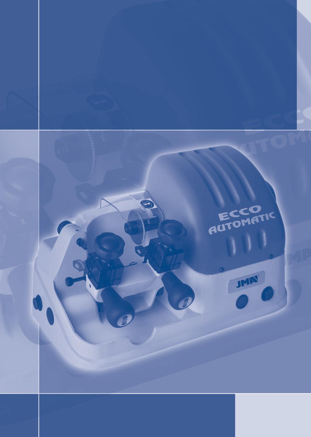
3 Presentation Machine and general aspects Characteristcis. General aspects The ECCO-AUTOMATIC copying machine has been designed taking current EEC safety regulations into account. The safety of the personnel involved in the handling of this type of machines can only be achieved with a well-designed personal safety programme. This involves the introduction of a maintenance programme and the following of certain recommendations, together with compliance with the safety regulations mentioned in this manual. The ECCO-AUTOMATIC is an automatic copying machine that is both robust and precise. It is designed to duplicate flat keys of cylinder locks, car keys, and cruciform (cross-shaped) and special keys.. Family of keys The ECCO-AUTOMATIC machine copies the following types of keys: - Flat keys. - Car keys. - Cruciform keys. Although the installation of the machine is straightforward, we recommend that you should not try to install, adjust, or handle it without first reading this manual. The machine leaves the factory ready for use; it only needs to be calibrated for the use that it will be given.. The ECCO-AUTOMATIC machine is presented in a tough cardboard box, protected by packing foam, of the following dimensions: Width = 0 mm, length = 0 mm, height = 0 mm Weight of the machine plus packaging = Kg. When you unpack the machine, inspect it carefully in case it has been damaged in transit. If you find any anomaly, notify the haulier immediately and do not touch the machine until the haulier s agent has carried out the corresponding inspection. To move the machine from one place to another, we advise you to lift the machine only by its base.. Transport and packaging Identifying label The ECCO-AUTOMATIC copying machine has the following identifying label specifying the serial number or number plate of the machine, the name and address of the manufacturer, the EC mark, and the year of manufacture. See figure. 8. Head Neck Upper stop Lower stop Notching Bit Blade Tip 8 0 Cutter Brush Cutter guard Motor guard -side clamp Clamp handle Slide Slide handles Positioners Slide advance limiter Feeler Depth adjustment command of the feeler Feeler blocking screw Motor/brush start-up push-button Motor start-up front push-button Red ignition pilot light See figure Emergency switch for stopping the milling cutter. Nomenclature of the key Main elements of the machine Technical data The main technical data are quoted below: Motor: Single-phase 0V, 0Hz, 0.8Kw, 0 rpm,. A. or Single-phase 0V, 0Hz, 0.8Kw, 00 rpm,. A. Cutter: High speed steel (HSS) Δ x x mm. Cutter turning speed:,0 rpm. Clamps: Of steel with trunnion sides. Displacement of the slide: Automatic, on self-lubricating bearings, and activated by an off-centre motor-reducer. Actual run: Axis X = mm. = maximum copying length. Dimensions: Width = 0 mm, depth = mm, height = 80 mm. Weight: Kg.
4 Effectiveness and operation. Components and functional parts. Machine adjustment.. Accessories See figure 8-size fixed spanners Spanners for lateral and depth adjustment of the machine Wedges for the tip stop of the key Wedges with notches for copying cruciform keys Set of Allen keys (,.,,, ). Rods of Δ.0 Rods of Δ.0 The ECCO-AUTOMATIC copying machine has types of adjustment (Lateral, Depth of cut, and Positioners). The copying machine is supplied with three adjustments having been carried out, as these are determined during the assembly stage of the machine. Only in exceptional cases will the machine need a lateral adjustment or an adjustment of the positioners. In contrast, each time the cutter is changed a depth of cut adjustment must be carried out if optimum copying quality is to be guaranteed... Electrical circuit See figure 0 The main components of the electrical and electronic circuits are as follows: 8 Current collector Circuit breaker Motor Motor-reducer Microswitches Front push-button (copying) Left-hand side push-button (brush) Red pilot light Emergency switch for stopping the milling cutter.. Emergency switch for stopping the milling cutter See figure To prevent accidents, this automatic key-cutting machine is equipped with an emergency switch, located on the front right part of the machine. In case of emergency, block this switch to stop the cutter from turning. The cutter will stop immediately, although the slide will continue to move forward until it has finished the coding cycle. If the slide should hit an obstacle, the motor controlling it will require extra power to move the slide, and the slide will stop. It will continue working when the obstacle is removed. NOTE: While the emergency switch is blocked, the milling cutter cannot be turned (by starting a coding cycle or by pressing the button that works the plane). If you wish to continue using the machine (turning the milling cutter), the emergency switch must therefore be unblocked... -side clamp The clamp is designed to secure different families of keys on each side. The figure shows the copying possibilities on each of the sides of the clamp. ) The copying of a key with support on the blade: Side : Keys with normal bit. Side : Keys with narrow bit. ) The copying of a key by trunnion on the guide (profile): Side : Keys with a guide on the lower part. Side : Keys with a guide on the upper part. See figure ) The copying of NEIMAN-type keys by trunnion on the guide. See figure.. Side control and adjustment Secure the adjustment keys () on face no. of the clamps, going as far as the tip stop plates () (with these inserted into the groove located further to the right). Unblock the slide and bring the clamps near to the copying index (I) and the cutter (F). To do this, the steps below must be followed: - Start the cutting cycle. - When the feeler touches the bit of the key, turn off the machine by activating the general switch located at the back. - At this point, unplug the power cable as a safety measure. Bring the clamps with the adjustment keys () towards the copying index (I) and the cutter (F), in such a way that the adjustment keys are correctly positioned regarding the copying index and the cutter. If the notches of the adjustment keys do not duly coincide with the copying index and the cutter, proceed as follows: - By loosening slightly the studs (T) of the axis we can move the cutter to the right or to the left. The cutter should be moved to a position in which it coincides on the notch of the corresponding adjustment key. To carry out this operation it is necessary to release the motor guard in advance. - The distance is thus adjusted, with the copying index (I) and the cutter (F) coinciding in the respective rebates of the adjustment keys. Secure the studs (T) of the axis. Finally, move the slide manually towards the furthest position on the left, and block it by pressing downwards. Activate the general machine switch again. Take great care, as when this switch is activated again the machine will start up instantaneously until the cutting cycle that had been started before turning off the machine is completed. NOTE: After a lateral adjustment, an adjustment of the positioners is always carried out. See figure 8.. Control and adjustment of the depth of cut Secure the adjustment keys () on face no. of the clamps, going as far as the tip stop plates () (with these inserted into the groove located furthest to the right). Unblock the slide and bring the clamps nearer to the copying index (I) and the cutter (F). To do this, the steps below must be followed: - Start the cutting cycle.
5 - When the feeler touches the bit of the key, turn off the machine by activating the general switch located at the back. - At this point, unplug the power cable as a safety measure. Bring the clamps with the adjustment keys () towards the copying index (I) and the cutter (F), in such a way that the adjustment keys rest on the copying index and the cutter. Turn the cutter by hand. If it touches the adjustment key slightly, the machine is correctly adjusted. If when the cutter is turned it moves freely without touching anything, this indicates that the cutter is retarded in relation to the feeler and that the machine cutting is insufficient. On the contrary, if the cutter is blocked at the adjustment key, this means that the cutter is ahead of the feeler and that the machine cutting is excessive. If any of these incidents occur, proceed as follows: - Release the stud (L) blocking the copying index (I) and turn the micrometric screw (H). - Advance or retard the copying index until the cutter turns and touches the adjustment key slightly. Then tighten the screw (L) of the copying index and the machine will be operating perfectly. Finally, move the slide manually towards the furthest position on the left, and block it by pressing downwards. Activate the general machine switch again. Take great care, as when this switch is activated again the machine will start up instantaneously until the cutting cycle that had been started before turning off the machine is completed. See figure.. Control and adjustment of the positioners The left face of the positioner on the right-hand side (P) must coincide with the left-hand side of the cutter (F) when the slide is to the extreme right; these sides of the cutter and the positioner determine the start of the copying cycle for the key. In order to carry out this adjustment, follow the steps below: - Turn off the machine by using the general switch to the rear. - Unblock the slide and move it manually to the extreme right; release the slide when this position is reached. - On supporting the tip stop plate () on the lefthand side of the cutter (F), the left-hand side of the positioner (P) must coincide with the tip stop plate (). - If this does not occur, release the stud (T) securing the positioner (P) and secure it again in its correct position. The distance between the right positioner (P) and the left positioner (P) must coincide with the distance between the cutter (F) and the copying index (I). In order to carry out this adjustment therefore, follow the steps below: - Keep the machine switched off and the slide in an extreme right-hand position. - On supporting the tip stop plate () on the lefthand side of the copying index (), the left-hand side of the positioner (P) must coincide with the tip stop plate (). - If this does not occur, release the stud (T) securing the positioner (P) and secure it again in its correct position. Finally, replace the slide in the rest position. See figure 0. Key copying operation BEWARE! When used correctly, the ECCO-AUTOMATIC copying machine is absolutely safe. However, it should not be forgotten that the work cycle is automatic and does not involve handling by the operator. Therefore, if the copier should involuntarily move his/her hands too close to the work area of the machine, there may be a risk of cut or crushed fingers. In case of emergency, block this switch to stop the cutter from turning. BEWARE! To work in total safety during the various copying stages, follow these instructions: Work with dry hands. The cutter guard should be in place in any copying operation. Use protective goggles. Make sure the machine is connected to earth. Do not move hands near the cutter when it is in operation. Only turn on the machine when slide operations have finished (secure key in the clamp, etc).. Copying a key Turn the clamps in order to locate the correct blocking side of the key, according to the type of key to be copied. Both the original key and the key blank should be introduced through the left side of the respective clamps. To make a copy, place the original key in the lefthand clamp and the key blank in the right-hand clamp, making sure to: - Support the key stop against the positioner. - Press the clamp, keeping the blade of the key duly supported on the base of the clamp. Remove the positioners. Unblock the slide by pressing downwards, and drag it in this position towards the extreme right. In this position, release the slide gently. Press the two start-up push-buttons at the same time (for some seconds). These buttons are the one on the left-hand side of the machine and the one on the front of it. The copying cycle will begin. This cycle will last approximately 0 seconds. At the end of the copying cycle, the cutter and the slide stop automatically. Block the slide again in its rest position by pressing downwards, and later release it gently. Release the keys from the clamps. Activate the brush by using the left-hand side push-button in order to eliminate the shavings. NOTE: The front red pilot light is always on and indicates that the copier is being supplied with power. NOTE: For optimum operation of the machine, it is advisable to replace the cutter when it is worn or blunt. It must be taken into account that the time the cutters lasts depends on several factors (mainly on the material of the keys being copied) but as a guide the cutter may be said to be capable of cutting some 000 keys.
6 Maintenance and safety.. Copying a key without a stop Introduce the two wedges () into one of the vertical grooves (R) of each clamp, depending on the length of the key to be copied. Support the tips of the keys against the wedges (). The keys will thus be adjusted. Finally, press the clamps and withdraw the wedges (). Before starting the cutting cycle, check that the start of the notching of the key is to the right of the tip of the feeler (to make sure that all the teeth of the key will be reproduced), and that the head of the key is to the left of the tip of the feeler (to make sure that there will not be an undesired collision between the head of the key and the tip of the feeler). See figure.. Copying a cruciform key This type of key is copied on side of the clamp. The keys must always be introduced into the clamps from left to right. Introduce the two wedges (), with the opening or rebate facing upwards, into one of the vertical grooves (R) of the clamp, depending on the length of the key to be copied. Support the tips of the keys against the wedges (). The keys will thus be adjusted. Finally, press the clamps and withdraw the wedges (). The cutting of the key is carried out in three operations, turning and supporting each time the stop of the key against the wedge (). Before starting the cutting cycle, check that the start of the notching of the key is to the right of the tip of the feeler (to make sure that all the teeth of the key will be reproduced), and that the head of the key is to the left of the tip of the feeler (to make sure that there will not be an undesired collision between the head of the key and the tip of the feeler). See figure When carrying out any maintenance operation, the following conditions must be complied with: Never carry out any maintenance with the machine in operation. The electric power cable must be disconnected. The instructions in this manual must be closely followed. Use original spare parts.. Changing the cutter To change the cutter proceed as follows: Turn off the machine using the general switch and disconnect the power cable. Loosen the two studs of the cutter guard and remove it momentarily. Using the two 8-size fixed spanners, block the axis of the cutter and release the nut (K) left-hand thread securing the cutter (F). Replace the cutter and finally replace the cutter guard. After changing the cutter it is advisable to carry out a lateral and depth adjustment of the copier.. Changing the brush To change the brush proceed as follows: Turn off the machine using the general switch and disconnect the power cable. Loosen the two studs of the cutter guard and remove it momentarily. Using the two 8-size fixed spanners, block the axis of the cutter and release the screw (R) using an Allen key. Replace the brush and finally replace the cutter guard. Adjusting the depth of the slide See figure This adjustment serves to protect the clamps from possible collisions between the feeler and the cutter. The distance between the cutter-feeler and the clamps should be about 0. mm. If this distance is changed, proceed as follows: Unblock the slide and bring the clamps near to the feeler and the cutter. In order to do this, follow the steps below: - Place any key in the left-hand clamp and start the cutting cycle. - When the feeler is more or less in the middle of the bit of the key, turn off the machine by activating the general switch to the rear. - Disconnect the power cable as a security measure. - Take out the key that was secured to the lefthand clamp. Loosen slightly the blocking stud (Z) using an Allen key. By turning the stop stud (W) clockwise or anticlockwise, the clamps can be moved towards or away from the cutter and feeler.
7 Once the distance adjustment has been carried out, block again the stop stud (W) by using a blocking stud (Z). Finally, move the slide manually towards the furthest position on the right, and block it by pressing downwards. Activate the general machine switch again. Take great care, as when this switch is activated again the machine will start up instantaneously until the cutting cycle that had been started before turning off the machine is completed. See figure. Safety recommendations Do not try to start up or handle the machine until all security aspects, installation instructions, the operating guide, and maintenance procedures have been considered and understood. Always cut off the power supply before carrying out any cleaning or maintenance work. Always keep the machine and its surroundings clean. Always work with dry hands. Protective goggles should be used even if the machine has protection elements. Make sure the machine has an earth connection. In case of emergency, block this switch to stop the cutter from turning.
TITAN-BIT KEY-CUTTING MACHINE INSTRUCTION MANUAL
 TITAN-BIT KEY-CUTTING MACHINE INSTRUCTION MANUAL Contents: 1 PRESENTATION AND GENERAL ASPECTS... 3 1.1 GENERAL POINTS... 3 1.2 TRANSPORT AND PACKING... 3 1.3 IDENTIFICATION LABEL... 3 2 CHARACTERISTICS
SENA INSTRUCTION MANUAL
 SENA INSTRUCTION MANUAL CONTENTS: 1 PRESENTATION AND GENERAL ASPECTS... 2 1.1 GENERAL POINTS... 2 1.2 TRANSPORT AND PACKING... 2 1.3 IDENTIFICATION LABEL... 2 2 CHARACTERISTICS OF THE MACHINE... 3 2.1
General Machine Instructions
 General Machine Instructions Cyclone Cyclone Plus Storm Storm Plus Note these instructions are based on the Cyclone machines, But the Cylinder Section is the same on the Storm Machines Tempest Tempest
OPERATION AND MAINTENANCE HANDBOOK D407270XA
 OPERATION AND MAINTENANCE HANDBOOK D407270XA vers. 1.0 Thank you for choosing one of Silca s high quality key cutting machines. This machine has been designed, tested and produced in our factory using
Operating manual. D425118XA vers.1.0
 Operating manual D425118XA vers.1.0 2004 SILCA S.p.A - Vittorio Veneto This manual has been drawn up by SILCA S.p.A. All rights reserved. No part of this publication may be reproduced or used in any form
SPIDA SAW OPERATIONS MANUAL
 SPIDA SAW OPERATIONS MANUAL CM SERIAL NUMBER. OCTOBER 2000 CONTENTS Page description 1.) Contents 2.) Safety First 3.) CM Overview 4.) CM Specifications 5.) CM Installation 6.) CM Operation Setting the
S E L E C T I O N. Arm Curl. User manual
 S E L E C T I O N T H E S T R E N G T H E V O L U T I O N User manual The identification plate of the and manufacturer, affixed behind the seat, gives the following details: A Name and address of the manufacturer
Thomas Scientific Swedesboro, NJ U.S.A.
 Thomas Scientific Swedesboro, NJ 08085-0099 U.S.A. Wiley Mini Mill 3383-L10 (115 V, 60 HZ) USE AND CARE OF CATALOG NUMBER: 3383-L10 Wiley Mini Mill (115 V, 60 HZ) PRELIMINARY 1. Mill has been properly
Operating, Servicing, and Safety Manual Model " Foot Shear CAUTION: Read and Understand
 Operating, Servicing, and Safety Manual Model 3000 52" Foot Shear CAUTION: Read and Understand These Operating, Servicing, and Safety Instructions, Before Using This Machine. SAFETY The purpose of the
TUCANA-02 P PORTABLE END MILLING MACHINE USER S MANUAL
 TUCANA-02 P PORTABLE END MILLING MACHINE USER S MANUAL 1 CONTENTS Page 1. General Information 3 1.1. Introduction 3 1.2. Manufacturer 3 2. Machine s Description and Purpose of Use 3 2.1. Machine s description
Elderfield & Hall, Inc., Kama Bandsaw AD 105S. Instruction Manual: Introduction to the Manual. General Precautions. Equipment. Machine.
 Elderfield & Hall, Inc., www.kooltools.com 10901 McBride Lane, Knoxville TN, 37932. Phone: 865.671.7682. Fax: 865.671.7686. Email: bob@kooltools.com Kama Bandsaw AD 105S 110 Volt, Single Phase 2 ¼ HP Portable
S E L E C T I O N. Upper Back. User manual
 and S E L E C T I O N T H E S T R E N G T H E V O L U T I O N User manual and and The identification plate of the and manufacturer, affixed to the frame on the side opposite the padded rest, gives the
Lumber Smith. Assembly Manual. If you are having problems assembling the saw and need assistance, please contact us at:
 Lumber Smith Assembly Manual If you are having problems assembling the saw and need assistance, please contact us at: 804-577-7398 info@lumbersmith.com 1 Step 1 Safety Carefully read the Owners Manual.
Z14 MANUAL TÉCNICO TECHNICAL MANUAL
 Z14 MANUAL TÉCNICO TECHNICAL MANUAL Z14 TECHNICAL INSTRUCTIONS CONTENTS: 1.- Opening the machine 2.- Changing the bridge 3.- Checking if cleaning and greasing is needed 4.- Puller runner bolts 5.- Tray
UNPACKING. Thank you for purchasing the Manual Capsule Filling Machine from KARISHMA PHARMA MACHINES.
 UNPACKING Thank you for purchasing the Manual Capsule Filling Machine from KARISHMA PHARMA MACHINES. Please take sufficient time and read this manual carefully before you start installation and operation
MANUAL BEVELLING AND DEBURRING SYSTEM B15 AIR
 MANUAL BEVELLING AND DEBURRING SYSTEM B15 AIR ord. No. 27 220 Operating Instructions for the device Subject to change 1 Table of Contents General Information 3 Description of the machine B15 AIR 3 Identification
4. Z-axis assembly. 4. Z-axis assembly. Written By: Josef Prusa manual.prusa3d.com Page 1 of 18
 4. Z-axis assembly Written By: Josef Prusa 2017 manual.prusa3d.com Page 1 of 18 Step 1 Get the necessary tools 13/17mm spanners 3.6mm flathead screwdriver Needle-nose pliers 2.5 and 1.5mm Allen key Step
30DC Speed Lathe Manual
 30DC Speed Lathe Manual The Crozier Model 30DC Speed Lathe is our most popular model. It has many standard features not found on any other machine in its class or price range. Standard Features 3/4 HP
Operating Manual. Original Instructions. D439848XA vers. 4
 Original Instructions D439848XA vers. 4 EN (c) 2012 SILCA S.p.a. Vittorio Veneto This manual has been drawn up by SILCA S.p.a. All rights reserved. No part of this publication can be reproduced or circulated
- 4 - Fig. 3b. Fig. 1b. Fig. 2. Fig. 2b MT 300
 MP 00 Manual 1 7 6 9 8 5 1 1 10 11 1 Fig. 1a Fig. 1b MT 00 Breite Buche Erle Pappel Balsa 0 0,5 0,8 0,8 0,8 max. Zustellung mm 0 0, 0,6 0,8 0,8 60 0, 0, 0, 0,8 80 0,1 0,1 0, 0,6 n Messerwelle = 6.000/min
Top spin Nr /
 Top spin Nr. 1840 0000 / 1840 1000 Bedienungsanleitung 21-6680 28052014 / A Made in Germany Ideas for dental technology Top spin Nr. 1840 0000 / 1840 1000 Contents 1. Introduction...2 1.1 Symbols...2 2.
3D PRINTER. Pack 11. Anything you can imagine, you can make! 3D technology is now available for you at home! BUILD YOUR OWN
 BUILD YOUR OWN Pack 11 Anything you can imagine, you can make! 3D PRINTER Compatible with Windows 7 & 8 Mac OS X 3D technology is now available for you at home! BUILD YOUR OWN 3D PRINTER CONTENTS PACK
JD-12. Instruction & Parts Manual
 JD-12 Instruction & Parts Manual Framon Manufacturing Company, Inc. 909 W Washington Avenue Alpena, MI 49707 Phone: 989-354-5623 Fax: 989-354-4238 E-mail: support@framon.com Website: www.framon.com The
Operating Instructions
 02 ENG 28.01.2008 9:14 Uhr Seite 11 Contents 1 Declaration of Compliance 2 Proper Use 3 Overview 4 General Safety Rules 5 Specific Safety Rules 6 Operation 6.1 Switching the paint remover On/Off 6.2 Locking
Table of Content. Machine Features and Functions. Specifications. Configuration and Working Principle 5. Machine Operation. Machine Adjustments
 Table of Content Safety Instructions Machine Features and Functions Specifications 2 3 4 Configuration and Working Principle 5 Machine Operation 7 Machine Adjustments 8 Machine Installation 9 Machine Remove
INSTALLATION MANUAL GIOTTO SCREEN
 INSTALLATION MANUAL GIOTTO SCREEN Before installing the Giotto screen, please read the following instructions carefully: The Giotto screen must be used INDOORS ONLY. It is forbidden to stay under the Giotto
Triplematic User manual
 Triplematic User manual Original instructions Document no: DOC-101. Issue: 1 Date: March 2016. 2016 Markusson Professional Grinders AB All rights reserved. Table of contents 1 Introduction.....................................................
Fig. 2 DORMA-Glas Stand/Issue 02/03 Seite/Page 1/7
 FSW Installation instructions Track rail 75 x 72 mm 1. Ceiling substructure and installation of the track rail (Fig. 1): The track rail must be bolted over its entire length (including the stacking track
Export Service Bulletin
 Applies To: Models With Sidewinder-Type Keys ALL Export Service Bulletin 01-077 October 2002 Cutting Sidewinder-Type Keys With the MATRIX H Key Cutting Machine (Supersedes 01-077, dated December 2001)
Flexproof-Cutter AF-30
 Habasit AG Postfach, CH-4153 Reinach-Basel Phone ++41 61 715 15 15 Fax ++41 61 715 15 55 Operating Instructions 3703 Author: Gul/Nyk Page 1 of 16 Replaces: Edition 9803 The is a device for preparing (die-cutting)
CHAINSAW SHARPENER MODEL: ECSS-1
 CHAINSAW SHARPENER MODEL: ECSS-1 Part No: 3402075 ASSEMBLY & INSTRUCTION MANUAL LS0409 INTRODUCTION Thank you for purchasing this CLARKE product Before attempting to use the product, it is essential that
Javelin Integra Inspired Design Precision Engineering
 Javelin Integra Inspired Design Precision Engineering USER INSTRUCTIONS Thank you for choosing the Keencut Javelin Integra. Every effort has been made to bring you a precision engineered product with the
Basic steps to time the Gammill quilting machine s rotary sewing hook
 Basic steps to time the Gammill quilting machine s rotary sewing hook 1.) Turn the machine off and unplug it. 2.) With the needle bar in the raised position, remove the bobbin and bobbin case. 3.) Remove
Operation manual for Core-drill (cutter) sharpening machine KBS/2
 sharpening machine KBS/2") Operation manual for Core-drill (cutter) sharpening machine KBS/2 Origina version Please keep for further use Kaindl-Schleiftechnik D-75203 Königsbach-Stein Remchinger Str. 4 Germany Tel.: +49 7232 / 4001-0
Operation manual for Core-drill (cutter) sharpening machine KBS/2 Origina version Please keep for further use Kaindl-Schleiftechnik D-75203 Königsbach-Stein Remchinger Str. 4 Germany Tel.: +49 7232 / 4001-0
Quill Stop V2 Installation Guide 11/16/2014
 Thank you for purchasing the Quill Stop for the Sieg X3 (Grizzly G0463) and SX3 (Grizzly G0619) mills. Your feedback is always appreciated. Please email questions and comments to gregpriest@cox.net. What
Due to possible damage in shipping, the vertical stop assembly has been removed from this machine.
 Due to possible damage in shipping, the vertical stop assembly has been removed from this machine. To assemble, insert the threaded rod through the shroud opening in the top of the machine. Start the four
SAM. Model: STV-C65 LCD Mobile Visualized Stand Instruction Manual. Weight Capacity: 1251bs / 56.7kg Suits LCD Flat Panel Display: 42"-55" Page 20
 SAM Model: STV-C65 LCD Mobile Visualized Stand Instruction Manual Weight Capacity: 1251bs / 56.7kg Suits LCD Flat Panel Display: 42"-55" 20 Step 6 LCD Mobile Lift Stand Model: STV-C65 Cable management
MODEL T " SPIRAL CUTTERHEAD INSTALLATION INSTRUCTIONS
 MODEL T27449 8" SPIRAL CUTTERHEAD INSTALLATION INSTRUCTIONS The Model T27449 indexable insert spiral cutterhead is designed to replace the straightknife cutterhead on the Grizzly jointer Model G0490W/G0490XW
Tapping Screw (W/Flange) 46 Cord Armor 47 Tube (D) 48 Cord. 45 Cord Clip. Tapping Screw (W/Flange) 10 Gear Cover Ass'y. 12 Socket (B) Ass'y
 46 Cord Armor 47 Tube (D) 48 Cord. 45 Cord Clip. Tapping Screw (W/Flange) 10 Gear Cover Ass'y. 12 Socket (B) Ass'y") W8VB The exploded assembly drawing should be used only for authoized service center. W8VB Item No. Part time 1 Magnetic Hex. Socket 2 Sub Stopper 3 O-Ring (S-16) 4 Locator (A) 5 Lock Sleeve (A) 6 O-Ring
W8VB The exploded assembly drawing should be used only for authoized service center. W8VB Item No. Part time 1 Magnetic Hex. Socket 2 Sub Stopper 3 O-Ring (S-16) 4 Locator (A) 5 Lock Sleeve (A) 6 O-Ring
8 x 5 PLANER THICKNESSER OPERATING INSTRUCTIONS MODEL: W588
 8 x 5 PLANER THICKNESSER OPERATING INSTRUCTIONS MODEL: W588 Charnwood, Cedar Court, Walker Road, Bardon, Leicestershire, LE67 1TU Tel. 01530 516 926 Fax. 01530 516 929 Email; sales@charnwood.net website;
S E L E C T I O N. Vertical Traction. User manual
 and S E L E C T I O N T H E S T R E N G T H E V O L U T I O N User manual and and The identification plate of the and manufacturer, affixed behind the backrest, gives the following details: A Name and
Geology, Prospectors, Mining, Metallurgy, Assaying, Environmental, Geotechnical
 LEGEND INC. Geology, Prospectors, Mining, Metallurgy, Assaying, Environmental, Geotechnical 988 Packer Way Sparks, NV 89431 Tel: (786) 786-3003 Fax: (775) 786-3613 Email: info@lmine.com Web: www.lmine.com
Inventory (Figure 2)
") MODEL T24631 8" SPIRAL CUTTERHEAD Installation INSTRUCTIONS For questions or help with this product contact Tech Support at (570) 546-9663 or techsupport@grizzly.com Introduction The Model T24631 spiral
MODEL T24631 8" SPIRAL CUTTERHEAD Installation INSTRUCTIONS For questions or help with this product contact Tech Support at (570) 546-9663 or techsupport@grizzly.com Introduction The Model T24631 spiral
OPERATING INSTRUCTIONS MODULGRAV. Tel. +49 (0) Fax +49 (0) homepage:
 Fax +49 (0) homepage:") OPERATING INSTRUCTIONS MODULGRAV Kolpingstraße -7 D-784 Singen / Htwl. Postfach 80 D-784 Singen / Htwl. Tel. +49 (0) 77 88-0 Fax +49 (0) 77 88 66 e-mail: info@elma-ultrasonic.com homepage: www.elma-ultrasonic.com
OPERATING INSTRUCTIONS MODULGRAV Kolpingstraße -7 D-784 Singen / Htwl. Postfach 80 D-784 Singen / Htwl. Tel. +49 (0) 77 88-0 Fax +49 (0) 77 88 66 e-mail: info@elma-ultrasonic.com homepage: www.elma-ultrasonic.com
 GENERAL OPERATIONAL PRECAUTIONS WARNING! When using electric tools, basic safety precautions should always be followed to reduce the risk of fire, electric shock and personal injury, including the following.
Band-Master ATS Nano Pneumatic Banding Tool Operating Instructions
 Band-Master ATS 601-118 Nano Pneumatic Banding Tool CONTENTS 601-118 Overview... 3 Safety.... 5 Initial Tool Set-up... 5 Regulator assembly mounting... 5 Attach tool head to regulator.... 6 Operating instructions...
12mm (Max) 6mm (Max) 82mm (Max) 12mm (Max) 6mm (Max)
 6mm (Max) 82mm (Max) 12mm (Max) 6mm (Max)") 1 1 2 2 3 3 82mm (Max) 12mm (Max) 12mm (Max) 6mm (Max) 4 4 5 6 8 6mm (Max) 0.5 0mm 1 5 6 7 7 8 9 9 A = B 10 11 12 D B 1 13 14 15 0 C A D E 16 17 18 F G D B N H J G I K 19 A 20 G L 21 C K 1mm L M 1mm 22
1 1 2 2 3 3 82mm (Max) 12mm (Max) 12mm (Max) 6mm (Max) 4 4 5 6 8 6mm (Max) 0.5 0mm 1 5 6 7 7 8 9 9 A = B 10 11 12 D B 1 13 14 15 0 C A D E 16 17 18 F G D B N H J G I K 19 A 20 G L 21 C K 1mm L M 1mm 22
OPERATING INSTRUCTIONS
 OPERATING INSTRUCTIONS Manually-operated die cutter flex and step flex AFZ-1200 H08M000057 1 HABASIT ITALIANA S.P.A. VIA MEUCCI, 8 I 31029 VITTORIO VENETO (TV) MACHINE MODEL: AFZ-1200 AND AFZ-1200/P DESCRIPTION:
Pow-R-Feed Systems Service Manual
 Pow-R-Feed Systems Service Manual Important Safety Instructions Please read this manual carefully and follow its instructions. Improper use or failure to follow these instructions could result in serious
Cut-True 16M Manual Paper Cutter
 Cut-True 16M Manual Paper Cutter 2/2013 OPERATOR MANUAL FIRST EDITION TABLE OF CONTENTS TOPIC PAGE Specifications 1 Safety Guidelines 1 Assembly 2 Overview 3 Description of Equipment Parts 3-4 Operation
ABM International, Inc.
 ABM International, Inc. Lightning Stitch required 1 1.0: Parts List head and motor assembly (Qty. 1) Reel stand (Qty. 1) Needle bar frame clamp (Qty. 1) Motor drive (Qty. 1) 2 Cable harness with bracket
SUPER PRO GUN & SUPER PRO GUN II
 MAGNUM VENUS PRODUCTS Maintenance & Repair Manual Part No. M6707-1-1 Revision 04.14.01 Maintenance & Repair Corporate HQ & Mfg. Phone: (727) 573-2955 Fax: (727) 571-3636 Email: info@magind.com Web: www.magind.com
Model 72D Twin Blade Rotary Wire Stripper
 110 Fairgrounds Drive P.O. Box 188 Manlius, NY 13104-0188 USA 315.682.9176 FAX: 315.682.9160 OPERATOR S MANUAL Model 72D Twin Blade Rotary Wire Stripper PRODUCTION WIRE PROCESSING EQUIPMENT Website: www.carpentermfg.com
1. Turn off or disconnect power to unit (machine). 2. Push IN the release bar on the quick change base plate. Locking latch will pivot downward.
. 2. Push IN the release bar on the quick change base plate. Locking latch will pivot downward.") Figure 1 Miniature Quick Change Applicators, of the end feed type, are designed to crimp end feed strip terminals to prestripped wires. Each applicator is set up to accept the strip form of certain specific
Figure 1 Miniature Quick Change Applicators, of the end feed type, are designed to crimp end feed strip terminals to prestripped wires. Each applicator is set up to accept the strip form of certain specific
Electric Router. Please read and fully understand the instructions in this manual before operation and keep this manual safe for future
 Electric Router FOR HELP OR ADVISE ON THIS PRODUCT PLEASE CALL OUR CUSTOMER SERVICE HELP LINE : 0509 500400 THE MANUFACTURER RESERVES THE RIGHT TO ALTER THE DESIGN OR SPECIFICATION TO THIS PRODUCT WITHOUT
10 SLIDING MITRE SAW MODEL NO: CMS10S2
 10 SLIDING MITRE SAW MODEL NO: CMS10S2 PART NO: 6461514 OPERATION & MAINTENANCE INSTRUCTIONS LS0312 INTRODUCTION Thank you for purchasing this CLARKE 10 Sliding Mitre Saw. Before attempting to use this
ATD AMP Variable Speed Reciprocating Saw Owner s Manual
 ATD-10535 7 AMP Variable Speed Reciprocating Saw Owner s Manual Manufactured in China To ATD Tools, Inc. Specifications TECHNICAL SPECIFICATIONS Voltage: 120V Frequency: 60Hz Power input: 7 Amps No load
REC Series Rack Installation Guide
 REC Series Rack Installation Guide 1 REC Series Rack Installation Guide TABLE OF CONTENTS SECTION SAFETY WARNINGS 1 600 WIDE EXPLODED VIEW 2 800 WIDE EXPLODED VIEW 3 SWITCHING DOOR HANDING 4 STABILIZING
Pencil Hardness Tester BEVS 1301
 Pencil Hardness Tester BEVS 1301 User Manual PAGE 1 1. Introduction BEVS pencil hardness tester offers an easy to use method for the determination of film hardness for a coating applied to a flat substrate,
Cutting Off Saw. Model:TV-350. Operation Manual
 Cutting Off Saw Model:TV-350 Operation Manual 1 Table of content 1. Introduction..3 1.1 General...3 1.2 Safety regulations.3 1.3 Guarantee.. 4 2. Technical data.. 4 2.1 Main groups...4 2.2 Survey and sketch
Operators Manual (Manual A)
") CD201 SINGLE COLUMN CARD DISPENSER Operators Manual (Manual A) Contents A1 Scope... 1 A2 Specifications... 1 A3 Installation... 2 3.1 Unpacking and inspection... 2 3.2 Opening and closing the door... 2
CD201 SINGLE COLUMN CARD DISPENSER Operators Manual (Manual A) Contents A1 Scope... 1 A2 Specifications... 1 A3 Installation... 2 3.1 Unpacking and inspection... 2 3.2 Opening and closing the door... 2
Inventory (Figure 2)
") MODEL T10130/T10126 6" & 8" SPIRAL CUTTERHEAD INSTRUCTIONS The Model T10126/T10130 indexable insert spiral cutterheads are designed to replace straightknife cutterheads from the Grizzly jointer Models
MODEL T10130/T10126 6" & 8" SPIRAL CUTTERHEAD INSTRUCTIONS The Model T10126/T10130 indexable insert spiral cutterheads are designed to replace straightknife cutterheads from the Grizzly jointer Models
CS Unitec, Inc. 22 Harbor Avenue, Norwalk, CT Phone: Toll-free:
 CS Unitec, Inc. 22 Harbor Avenue, Norwalk, CT 06850 Phone: 203-853-9522 Toll-free: 800-700-5919 Email: info@csunitec.com CS Unitec, Inc. 22 Harbor Avenue, Norwalk, CT 06850 Phone: 203-853-9522 Toll-free:
IRM 2500 Rotation plate for oval rings (operating manual)
") IRM 2500 Rotation plate for oval rings (operating manual) Laban-Produkttechnik Table of contents Table of contents 1 Introduction / information for the user... 3 1.1 Purpose of this operating manual...
IRM 2500 Rotation plate for oval rings (operating manual) Laban-Produkttechnik Table of contents Table of contents 1 Introduction / information for the user... 3 1.1 Purpose of this operating manual...
Removing and Replacing the Y-truck
 Service Documentation Removing and Replacing the Y-truck To remove and replace the Y-truck you will need the following tools: 4mm Allen wrench 12mm stamped flat wrench #2 Phillips screwdriver (magnetic
TAKE-A-LABEL Power Dr. Nunica, MI Phone (616) Fax (616)
 Fax (616)") OPERATIONS MANUAL MODEL TAL-3100C CONTINUOUS DUTY TAMP- LABELER TAKE-A-LABEL 16900 Power Dr. Nunica, MI 49448 Phone (616) 837-9300 Fax (616) 837-9301 http://www.take-a-label.com E-Mail: sales@take-a-label.com
OPERATIONS MANUAL MODEL TAL-3100C CONTINUOUS DUTY TAMP- LABELER TAKE-A-LABEL 16900 Power Dr. Nunica, MI 49448 Phone (616) 837-9300 Fax (616) 837-9301 http://www.take-a-label.com E-Mail: sales@take-a-label.com
Side Winder R o u t e r L i f t.
 Woodpeckers PRECISION WOODWORKING TOOLS Side Winder R o u t e r L i f t. INSTALLATION INSTRUCTIONS The wrench handle must be pointing left in order to fully insert or remove it. Lift Wrench Once fully
Knife grinding machine K3 H/K
 Knife grinding machine K3 H/K 01.11.2010 GS-Schleiftechnik, Leyher Str. 61 a, D-90431 Nürnberg Phone 0049/9193/4404, Fax 0049/9193/4391 e-mail: info@gs-de.eu 1 Table of Contents A. SAFETY... 3 A.1 THE
UK10 UK11. First published: June No.KX03023
 UK10 UK11 First published: June 2003 No.KX03023 INTRODUCTION Thank you for purchasing Kansai Special s UK series machine. Please study this instruction manual carefully before operating the machine. 1.
Referencing 0,0 position
 Page 1 of 11 TITLE: SABRE X-Axis Lead Screw Replacement Procedure Gerber FastFact #: 2013 Supplied by: Gerber Hardware Support Last Modified: March 1, 2011 Summary: The following procedure explains how
Pocket Door Kit PD1 / PD2 Installation Instructions. Kit Contents.
 Pocket Door Kit PD1 / PD2 Installation Instructions Kit Contents. 1, Create Rough Opening In Stud Wall Construct rough opening ensuring all sides are square and level. Rough opening should be; Height =
Maintenance Information
 16601023 Edition 2 January 2014 Air Impact Wrench 2705P1 Maintenance Information Save These Instructions Product Safety Information WARNING Failure to observe the following warnings, and to avoid these
Magnetic Base Drilling Machine A100/32. Operators Instruction Manual And Spare Parts Listings
 Magnetic Base Drilling Machine A100/32 Operators Instruction Manual And Spare Parts Listings Index Chapter 1. Technical Overview. Chapter 2. Warnings and Safety Instructions. Chapter 3. Operating Instructions.
CONDITIONS OF SALE AND WARRANTY
 CONDITIONS OF SALE AND WARRANTY 1. Read carefully this operator's handbook before operating our P35 corking machine. 2. F.lli Marchisio & C.Spa guarantees his P35 corking machine in case of breakages caused
SawStop. Contractor Fence Assembly OWNER S MANUAL. Model CNS-SFA
 Contractor Fence Assembly OWNER S MANUAL Model CNS-SFA Warranty warrants to the original retail purchaser of the Contractor Fence Assembly accompanying this manual that the fence assembly will be free
10 BANDSAW OPERATING INSTRUCTIONS MODEL: W715
 Machinery & Tooling at its best! 10 BANDSAW OPERATING INSTRUCTIONS MODEL: W715 Charnwood, Cedar Court, Walker Road, Bardon, Leicestershire, LE67 1TU Tel. 01530 516926 Fax. 01530 516929 email; sales@charnwood.net
1) Place the reactor stand on a sturdy bench with the bottom plate facing toward the front.
 Place the reactor stand on a sturdy bench with the bottom plate facing toward the front.") Assembly Instructions for ChemRxnHub Reactor Systems 1) Place the reactor stand on a sturdy bench with the bottom plate facing toward the front. Loosen knobs on the right and left using 2 hands of the
Assembly Instructions for ChemRxnHub Reactor Systems 1) Place the reactor stand on a sturdy bench with the bottom plate facing toward the front. Loosen knobs on the right and left using 2 hands of the
Elcometer Muller Laboratory Grinder
 English Elcometer 2000 Muller Laboratory Grinder Operating Instructions English is a registered trademark of Elcometer Limited. All other trademarks acknowledged. Copyright Elcometer Limited. 2009. All
TWISTER. Operating manual DM vers.2.0. Members of the Kaba Group
 TWISTER Operating manual DM327039 vers.2.0 Members of the Kaba Group (c) 2001 - Vittorio Veneto This manual has been drawn up by SILCA S.p.A. rights reserved. No part of this publication may be reproduced
OPERATING INSTRUCTIONS
 ROTTERMANN AG CH-8832 Wollerau Tel. +41/44-687'10'01 Fax +41/44-687'10'11 info@rottermann.com Bevel trimmer ROGAtrim KS4-3p OPERATING INSTRUCTIONS I:\DATEN\TEXTE\7000\GEB_ANL\KS_TSGEB\GB_MAN\EKS4_3P.WPD
STOP. V00029AC Rev. 04 READ ALL OF THE FOLLOWING INSTRUCTIONS BEFORE REMOVING CABINET FROM SKID TOOL LIST. NET-ACCESS S-Type Network Cabinets
 Rev. 04 STOP READ ALL OF THE FOLLOWING INSTRUCTIONS BEFORE REMOVING CABINET FROM SKID NET-ACCESS S-Type Network Cabinets -Phillips screwdriver -Flatblade screwdriver -22mm socket wrench -15mm socket wrench
Quick Set Dovetail Jig
 Quick Set Dovetail Jig FOR HELP OR ADVISE ON THIS PRODUCT PLEASE CALL OUR CUSTOMER SERVICE HELP LINE : 01509 500359 THE MANUFACTURER RESERVES THE RIGHT TO ALTER THE DESIGN OR SPECIFICATION TO THIS PRODUCT
Operating manual D435566XA. vers. 3.0
 Operating manual D435566XA vers. 3.0 GB 2011 SILCA S.p.A - Vittorio Veneto This manual has been drawn up by SILCA S.p.A. All rights reserved. No part of this publication may be reproduced or used in any
DP-8 H. H. MØRCH. Instructions. Contents of the packing. Spatial requirements. Mounting the bush
 DP-8 Instructions H. H. MØRCH Contents of the packing In the packing of the tonearm you will find the arm base in which the bearings are encapsulated in a heavy body. This is the link between the moveable
INSTRUCTIONS FOR ASSEMBLING YOUR CLEARMOUNT MITER SAW SCALE
 INSTRUCTIONS FOR ASSEMBLING YOUR CLEARMOUNT MITER SAW SCALE Pictures shown are our SW7 but these instructions apply to all of our scales. Special information for other models is noted. ** Read & Follow
Before use please read & understand this manual, paying particular attention to the safety instructions.
 OPERATOR S MANUAL AND PARTS LIST 12 HAND PUSH ROLLER MOWER - THHMR Sales & Helpline 01793 333220 www.thehandy.co.uk Before use please read & understand this manual, paying particular attention to the safety
Profiform 200 Profiform 320. Operating manual
 Profiform 200 Profiform 320 Operating manual Profiform 200 / Profiform 320 Operating manual Page 1 Table of contents 1. General information Page 2 2. Profile of the Profiform sheet metal working machines
OPERATING INSTRUCTIONS
 OPERATING INSTRUCTIONS Rotary Microtome CUT 4062 / CUT 5062 / CUT 6062 CUT 6062 illustrated above INS1000GB 2012-01-06 Instructions CUT4062 / CUT 5062 / CUT 6062 2 CONTENTS 1. INTENDED USE... 4 2. SYMBOLS...
COMPLEX GRINDER OF MILL& DRILL
 COMPLEX GRINDER OF MILL& DRILL MODEL: MR-F6 OPERATING INSTRUCTION PLEASE REMEMBER 1. When using electric tools, machines or equipment, basic safety precautions should always be followed to reduce the risk
Solid Sample Holder Accessory
 Installation category I Pollution degree 2 Equipment class III Introduction The Solid Sample Holder for the Agilent Cary Eclipse is an accessory that enables you to perform fluorescence measurements on
Model:CB-MRC. Instruction Manual of Mini Recessed Motorized Screen
 GRANDVIEW REPRODUCING GENUINE COLORS GRANDVIEW REPRODUCING GENUINE COLORS Instruction Manual of Mini Recessed Motorized Screen Grandview Crystal Screen Canada Ltd. #11-3751 North Fraser Way, Marine Way
Hedge Trimmer Attachment HA110 HA850 Complément Taille-haie HA110 HA850 Tijeras cortasetos (suplemento) HA110 HA850
 HA110 HA850") Operator s manual Manual d utalisation Manual de instrucciones Hedge Trimmer Attachment HA110 HA850 Complément Taille-haie HA110 HA850 Tijeras cortasetos (suplemento) HA110 HA850 GB FR ES KEY TO SYMBOLS
Operator s manual Manual d utalisation Manual de instrucciones Hedge Trimmer Attachment HA110 HA850 Complément Taille-haie HA110 HA850 Tijeras cortasetos (suplemento) HA110 HA850 GB FR ES KEY TO SYMBOLS
installation instructions
 installation instructions Easi-Plan WC Frame 820mm with Dual Flush Cistern ref: EPWC-05-1005 Easi-Plan WC Frame 980mm with Dual Flush Cistern ref: EPWC-05-1505 EASI-PLAN installation instructions Parts
OPERATOR'S MANUAL ROUTER MOUNTING KIT
 OPERATOR'S MANUAL MOUNTING KIT 4950301 (FOR USE WITH BT3000 AND BT3100 TABLE SAWS) Your new router mounting kit has been engineered and manufactured to Ryobi's high standard for dependability, ease of
Dust Collector. Model No: DC2200 (FM300S)
") Dust Collector Model No: DC2200 (FM300S) GENERAL SAFETY INSTRUCTIONS Before attempting to operate this machine, it is important that you read, understand and follow these instructions very carefully. They
Dust Collector Model No: DC2200 (FM300S) GENERAL SAFETY INSTRUCTIONS Before attempting to operate this machine, it is important that you read, understand and follow these instructions very carefully. They
Instruction Manual. Manual Furniture Mover. Note: Owner/Operator must read and understand this instruction manual before using the furniture mover.
 Instruction Manual Manual Furniture Mover Note: Owner/Operator must read and understand this instruction manual before using the furniture mover. I - Contents 1. Application 2 Specifications 3.Assembly
OWNERS MANUAL FOR MEC 306XP/408XP WOBBLE
 OWNERS MANUAL FOR MEC 306XP/408XP WOBBLE PLEASE READ AND FULLY UNDERSTAND THE INSTRUCTIONS PRIOR TO SETTING OR TUNING THE MACHINE. Page 1 CAUTION: ANY MEC CLAY TARGET MACHINE MUST BE IN THE DISARMED STATE
END MILL RE-SHARPENER EMG-413
 END MILL RE-SHARPENER EMG-413 OPERATING INSTRUCTIONS -TABLE OF CONTENTS- A.SAFETY INSTRUCTIONS -------- 1 B.NAMES OF COMPONENTS ----- 2 C.OPERATIONS ------------------------ 3 D.REPLACING THE WHEEL --------
MODEL T " SPIRAL CUTTERHEAD INSTRUCTIONS
 MODEL T10125 6" SPIRAL CUTTERHEAD INSTRUCTIONS The Model T10125 spiral cutterhead is designed to replace the straight knife cutterhead on the Model G0452 6" jointer. The total procedure of changing the
IM-2 SE UNDERPINNER.!!! For your safety!!! Read the instructions manual carefully SAP: 0
 MANUAL IM-2 SE UNDERPINNER!!! For your safety!!! Read the instructions manual carefully SAP: 0 OPERATIONS 0504272 INTRODUCTION Congratulation upon your purchase of the INMES IM-2 SE Underpinner, designed