Hakki Pilke Falcon. The operator must read and understand these instructions before operating the firewood
|
|
|
- Norman Briggs
- 6 years ago
- Views:
Transcription
8 772 7300, Fax +358 (0)8 772 7320 info@maaselankone.fi www.")
1 ENGLISH 1 Hakki Pilke Falcon FIREWOOD PROCESSOR Instructions for assembly, operation and maintenance EC Declaration of Conformity Safety instructions Guarantee terms The operator must read and understand these instructions before operating the firewood MAASELÄN KONE OY Valimotie 1, FI Haapajärvi, Finland Tel (0) , Fax +358 (0) info@maaselankone.fi
2 2 1. General information Introduction Purpose of use Machine models and basic information Operating conditions Safety instructions Noise and vibration Warning symbols Setting up the machine for operation and transport Receipt inspection Main components of the machine Arranging the machine for operation and transport Connecting the machine to a power source Lifting and moving the machine Additional hydraulics connections Operating the machine Controls and functions of the machine Before using the machine Performing a test run on the machine Feeding and sawing wood Log splitting Using the output conveyor After use Maintenance and adjustment of the machine Disconnecting the machine from its power source Adjusting the log length Height adjustment of the splitting knife Replacing the splitting knife Adjusting the length of the splitting motion Adjusting the tightness and alignment of the output conveyor s belt Cutting blade and drive end Changing the oil Changing the oil of the multiplier gearbox Conveyor maintenance Lubrication... 32
3 Saw chain lubrication Solenoid and pressure regulating valves Washing and cleaning Storage Maintenance table Failures and remedial measures Cause-effect table for failures and their removal Jamming of the cutting blade Jamming of the wood on the splitting knife Connection diagram Hydraulics diagram (P.T.O model) Hydraulics diagram (Electric model) Guarantee terms and declaration of conformity EC Declaration of Conformity for the machine... 44
4 4 1. General information 1.1. Introduction The purpose of this manual is to ensure that the machine is used in the manner intended by the manufacturer, taking safety into consideration. Everyone operating the machine or working in close proximity to it must study this manual carefully. Operators of the machine are expected to have basic skills in tractor handling, such as utilising the cardan shaft drive and the tractor's lifting equipment. Before commencing work, operators must also familiarise themselves with the machine's control and safety equipment, and ensure their proper operation. Additional information on Maaselän Kone Oy's products is available on our website at Keep this manual in the immediate vicinity of the machine Purpose of use The Hakki Pilke Falcon firewood processor is designed for the preparation of firewood from pruned wood or logs. The firewood processor must not be used to process any treated wood, such as is found in construction waste. Sand, nails or other impurities in the wood may damage the machine. The maximum diameter of the logs to be split is 35 cm. This limit must not be exceeded. When estimating the diameter of the log you are about to split, note that the shape of the log and other factors, such as branches and burrs, make the actual diameter larger, and may prevent the log from being fed to the machine. Do not spit logs that exceed 50 cm in length Machine models and basic information Model TR Electricity Driving power Tractor's cardan shaft (TR) Electric motor Weight 865 kg 880 kg TR/Electrical drive min 25 hp/max 500 rpm 7,5 kw (min. 16 A, type D fuse) Height/width/length transport position 250/255/135 (cm) in transport position Input/output 220/400 (cm) conveyor Saw bar/chain bar: 16 groove 1.5 mm. chain: 67 loops, pitch Max log diameter 35 cm Max/min log length Log max 50 cm; min 17 cm The machine s serial number, manufacturing date, weight, operating voltage (electrically-operated machines) and model are indicated on the grey type plate located on the machine frame, below the locking latch of the output conveyor, on the right side of the operator.
5 1.4. Operating conditions 5 The temperature range within which the machine can be operated is -20 to +30 C. In the winter, the operator must ensure that there is no risk of slipping in the working area. The working area must be level and clear of unnecessary items. No unauthorised persons must enter the working area. The working area must also be sufficiently illuminated. These requirements must be met for the entire duration of the work. The machine may not be used indoors Safety instructions This device is intended to be operated by only one operator. The danger zone around the device is 10 metres. Persons under 18 years of age may not operate the machine. The operator must ensure that use of the device does not cause danger to others and that there are no unauthorised persons in the danger zone. The machine may not be operated while under the influence of alcohol or other drugs, or when tired. The machine may not be operated unless the operator has familiarised themselves with this instruction manual. The machine has been designed solely for the making of firewood. The machine must be placed in the transport position whenever it is moved. When transporting the machine on a public road, it must be equipped with additional lights. The operator is not permitted to modify the structure or operation of the machine, or to remove protective equipment. The operator must wear sufficiently tight-fitting work clothing, protective goggles and safety footwear. Before starting up the machine, the operator must ensure that the machine and its guards are intact. When powering the machine with a tractor, the operator must ensure that the cardan shaft is undamaged and that the rpm range is correct. The machine must be attached to the tractor's lifting equipment during operation. Before starting up the firewood processor, the operator must ensure that all the control and safety devices are functional. When cleaning or maintaining the machine, it must be disconnected from its power source. Note! Do not leave a running machine unsupervised! 1.6. Noise and vibration The vibration values do not exceed 2.5 m/s2.


6 Warning symbols Read the machine s manual before operating the machine. Wear eye and ear protection. Wear safety footwear and work gloves. Do not wear any loose items of clothing. Always grab the piece of wood or log from the side. Lifting point for forklift. Beware of moving parts. Beware of the cardan shaft. Beware of the chain. Beware of the splitting knife. Only one person may operate the machine. Disconnect the power supply before maintenance procedures.


7 7 The danger zone around the machine is 10 metres. Risk of crushing The maximum speed for the cardan shaft is 500 rpm. The rotation direction is in the direction of the arrow. The maximum permitted angle of the conveyor is 40. Do not walk under the conveyor. Hydraulic oil Saw chain oil Danger zone Lubrication point

8 2. Setting up the machine for operation and transport Receipt inspection Dispose of the machine s packaging materials in an environmentally friendly manner. Check that the machine has not sustained any damage during transit, and ensure that all necessary parts are included in the package. In the event of any defects or damage, contact the retailer immediately Main components of the machine The main components of the Hakki Pilke Falcon firewood processor are presented in the figure below. A. Input conveyor B. Control unit C. Cutting and splitting unit D. Output conveyor Figure 1. Main components of the machine

. 2. Remove the other end C of the support leg holder from the lug (Figure 2). Figure 2. 3.")
9 2.3. Arranging the machine for operation and transport 9 Before arranging the machine for transport, ensure that the operating conditions, detailed in Section 1.4, are met and review the safety instructions in Section 1.5. Note! Inspect and clean the machine before setting it up for transport! Placing the input conveyor in the operating or transportation position Place the input conveyor in the operating position as follows: 1. Ensure that sufficient room is available to lower the input conveyor (approx. 2 m). 2. Remove the other end C of the support leg holder from the lug (Figure 2). Figure Release the lock by removing cotter pin A in Figure 3 and turning locking latch B in Figure 2 out of its slot. Note! At the same time, hold the end of the input conveyor with your left hand! Figure 3.

10 10 4. Lower the input conveyor with your left hand while simultaneously using your right hand to guide support leg D in Figure 4 to slot E, as shown in Figure 4. When placing the input conveyor in the transport position, lift the conveyor to the upper position, turn locking latch B into its slot and insert cotter pin A, as illustrated in Figure 2. Use holder C to lock the support leg in place, as shown in Figure 2. Figure 4.

 for the discharge opening of the conveyor. Figure 5. 4.")
11 11 Placing the output conveyor in the operating or transport position Place the output conveyor in the operating position as follows: 1. Ensure that there is sufficient room for lowering the output conveyor. 2. Turn off the machine and disconnect it from the power source. 3. Keep lock A open and lower the output conveyor with a winch to its lowest position. Note! If the machine features a selfcleaning output conveyor, leave sufficient clearance (approx. 30 cm) for the discharge opening of the conveyor. Figure Turn the upper section of the conveyor into the operating position by using handle B in Figure 6. Figure 6.
 and lock the upper section of the output conveyor to the operating position using lock D in Figure 8.")

12 12 5. Turn support bar C of the output conveyor in Figure 7 to the side. 6. Use a winch to lift the conveyor to the desired angle (max 40 ) and lock the upper section of the output conveyor to the operating position using lock D in Figure 8. Figure 7. Figure 8. Place the output conveyor in the transport position as follows: 1. Turn off the machine. 2. Release lock D, shown in Figure 7, and lower the conveyor to the lowest possible position with the winch. 3. Turn support bar C in Figure 6 to a position over the belt, and turn the upper section of the conveyor onto the lower section using handle B in Figure Turn the conveyor to the middle position. See Section Turn splitting groove guard E in Figure 8 into the transport position, as shown in Figure Lift the conveyor with the winch until it locks into the raised position. Ensure that lock A (Figure 4) settles properly into place. Note! Do not stand on the output conveyor! Do not use the winch if the belt is worn!

13 2.4. Connecting the machine to a power source 13 Tractor-powered model A tractor-powered firewood processor must be connected to a three-point lifting device and the tractor's cardan shaft. Connecting the cardan shaft is a task for only one person. When connecting the machine to the tractor's lifting equipment, the tractor cabin must be free of people, in order to prevent any accidental contact with the controls. Check all the connecting devices of the tractor and the firewood processor before connecting them. Never use faulty equipment. Figure 9. When using the cardan shaft, observe any instructions that are provided by the manufacturer of the shaft. The machine requires 7.5 kw of power, which must be taken into account with regard to the capacity of the cardan shaft. A suitable cardan shaft is of power class four. Make sure that the connected shaft is locked to the splined shaft of the multiplier gear. Connect the chain that prevents the turning motion of the guard to hole B shown in Figure 9. Hang the cardan shaft from hook A in Figure 9 when the machine is not being operated and it is disconnected from the tractor. Finally, ensure that all the connections are safe and secure. Never use a damaged or unprotected cardan shaft. Note! Tractor-powered machines must be attached to the lifting equipment of the tractor.

, the current phase is incorrect. Figure 10.")
14 14 Electrically-powered model An electrically-powered machine functions with a power of 7,5 kw. The IP rating of the electric motor is 55. The fuse must be a min. 16 A type D fuse. The electrical cable must be at least 5 x 4 mm², and it must be connected to the socket in Figure 10. The firewood processor can be activated with the green starter button on the front section of the machine. Use the red button to turn off the machine. If the electric motor rotates in the wrong direction (i.e. the machine makes an abnormal noise and the hydraulic functions are inoperable), the current phase is incorrect. Figure 10. Electric motor connector. We recommend using an extension cord that allows you to switch the current phase, or an adapter. Note! If the extension cord does not have a phase switch, the electrical work related to changing the phase must only be performed by an electrician. Note! Only connect the machine to a fault current protected socket. Figure 11. Starter.

15 Lifting and moving the machine When moving the machine, make sure that the moving and lifting capacity of your tractor or forklift is sufficient for the weight of the machine (approx. 750 kg). Only lift the machine by the indicated lifting points or with the lifting equipment of the tractor. Figure 12. Lifting points of the machine When connecting the machine to the tractor's lifting equipment, the tractor cabin must be free of people, in order to prevent any accidental contact with the controls. Check all the connecting devices of the tractor and the firewood processor before connecting them. Never use faulty equipment. The pins that are used to connect the pushbars and drawbars to the machine must be of the correct size, and the appropriate locking pins must be used to secure them. The machine must be placed in the transport position if it is to be moved more than 5 metres. Exercise extreme caution when moving the machine in the operating position. Always lower the machine to the ground when you stop. Note! Incorrect lifting may cause a hazardous situation or damage the machine.


16 Additional hydraulics connections Using the quick couplings of the additional hydraulics Connect the additional hydraulics (e.g. log lifter) by pushing the auxiliary device s hydraulic hoses into quick couplings A and B in Figure 13. Use the quick couplings in Figure 13 with control lever B in Figure 15. Figure 13. Using the quick couplings of the auxiliary feed rollers The auxiliary feed rollers can be connected in series with the input conveyor. This way, the rollers are automatically synchronised to operate with the input conveyor when feeding logs with lever E. 1. Connect the auxiliary feed roller hoses to quick couplings C and D in Figure Open valve A in Figure 14, i.e. to the down, which allows oil to flow to quick couplings C and D shown in Figure Make sure that the rotation direction of the rollers is the same as the conveyor s direction. If necessary, change the order of the hoses in quick couplings C and D in Figure 14. Figure 14. Note! Always close valve A (turn it into the right) when quick couplings C and D in Figure 14 are not used!

17 17 3. Operating the machine 3.1. Controls and functions of the machine Figure 15. Controls Names and functions of the controls in Figure 15: A. Splitting cylinder control lever - Pushing the lever to the left returns the splitting cylinder to the initial position. - Pushing the lever to the right makes the splitting cylinder perform the splitting motion. B. Control valve for an auxiliary device, such as a log lifter, (accessory) C. Adjustment screw for the pressure of the bar s downward motion. Rotating the screw clockwise accelerates the bar s descent, and vice versa. Note! In the electrically-powered model, the adjustment screw is different and operates in the opposite way, meaning that rotating the screw anti-clockwise accelerates the bar s descent, and vice versa. D. Wood gripper handle. With the handle, wood can be pressed against the table during sawing in order to make cutting the wood as safe and stable as possible. E. Control lever for the saw bar and output conveyor. - Saw bar up/down: push the lever forward/backward - Input conveyor control right/left: push the lever to the upper right and upper left F. Adjustment of the running speed of the output conveyor (accessory). - Turning the knob anti-clockwise increases the output conveyor s speed. - The belt rotation slows down and eventually stops when the knob is turned clockwise. G. Height adjustment of the splitting knife.
18 Before using the machine Before the actual operation of the machine a test run and functional test must be carried out. Both the test run and testing can only be performed by a person who has studied the machine s manual. Before the test run, all of the components of the firewood processor must be checked. If any faults or wear and tear that may affect the safe use of the machine are discovered, the processor must not be used until the faulty or worn component is replaced and safe use can be ensured. Before using the machine, the operator must ensure that the machine has not sustained any damage the machine s operating environment is in accordance with Section 1.4 the machine is positioned on a solid foundation no unauthorised persons are within the machine s danger zone all guards and safety devices are in place and functional opening the splitting and cutting guard stops the machine s hazardous functions (see items 11, 15, 16 and 17 in Sections 3.3) the hydraulic hoses and pipes are undamaged (the pipes must be replaced if there is a tear in the hoses or pipes, if they leak, or if the surface layer of the hydraulic hose has worn all the way down to the supporting weave.) the machine does not leak oil the machine functions properly (Section 3.3). Note! Do not use the machine if the requirements listed above are not met! 3.3. Performing a test run on the machine 1. Check that the guard for the firewood processor's cutting and splitting section is down. 2. Check that the input and output conveyors are in the operating position. 3. Ensure that the splitting groove is empty. 4. Make sure that you are familiar with the functions of the machine's controls. If necessary, refer to Section Activation. 6. Tractor drive: Start the tractor and connect the output, starting with a slow speed and increasing the speed to a maximum of 410 rpm. 7. Electrical drive: Connect the cable to the socket of the firewood processor, start the machine by pressing the start button and wait a moment. This will activate the electric motor at full speed. 8. Activate the machine s splitting motion by lowering the saw bar fully into the lower position and lifting it back up using lever E (Figure 15). The splitting motion must be normal. The splitting motion can also be started by pulling lever A in Figure 15 to the right side. 9. Do the following to ensure that the blade chain lubrication functions automatically: (If necessary, see Section 4.12). a. Use lever E in Figure 15 to perform a few sawing motions without any actual logs. b. Turn off the machine and disconnect it from the power source. c. Open the guard and see if the blade chain has been supplied with oil.
19 Ensure that the saw chain begins running when you lower the saw bar by about 2 cm using lever E (Figure 15). Note! In cold weather, the saw valve shaft may be sluggish at first, which means that the saw bar must be driven to the bottom position pair times for the saw chain to run. 11. Start the splitting motion and stop it by opening the cradle guard of the cutting and splitting section. 12. Ensure that the splitting knife returns to the initial position (in the middle of the splitting motion) also by pushing lever B in Figure 15 to the left. 13. Test run the feed and return motion of the input conveyor using lever E in Figure 15 by pushing the lever to the upper right (belt runs to the right) and upper left (belt runs to the left). 14. Start the output conveyor by using control F in Figure 15 (accessory) to adjust the speed to an appropriate level for the conveyor. 15. Ensure that the guard does not open when the saw bar is spinning. 16. Ensure that the splitting motion or saw blade cannot be activated with the guard open. If a fault occurs during the test run, determine the cause of the fault and take remedial action as deemed necessary. The machine must be shut down and disconnected from the power source for the duration of both the diagnostics and repairs. Note! When the temperature of the hydraulic oil is <5 C, the lowering speed of the saw bar must be adjusted to a slower than normal level for at least 20 minutes. Once the oil has warmed up sufficiently, you can return the saw bar lowering speed back to normal. Note! Do not leave a running machine unsupervised! 3.4. Feeding and sawing wood The input conveyor feeds the wood to be processed into the machine. Feed wood into the machine using control lever E in Figure 15 of Section 3.1. When feeding wood into the machine, make sure that it does not present a risk of your clothes, hands or other parts getting caught in the machine, for example, due to the shape of the log. Do not use your hand to guide the log into the cutting section. Adjust the wood measuring device to the desired length and make sure that the speed of the output conveyor belt is suitable by adjusting it. 1. Choose the log to process. Note that the maximum log diameter is 35 cm. The knottiness and shape of the log increase the diameter. 2. Use the input conveyor to feed wood into the cutting section by pushing lever E in Figure 15, Section 3.1, to the upper right position. You can cancel the feed by pushing lever E to the upper left position. 3. Once the log stops for cutting in the mechanical measuring device, lock the log in place with the wood press by pressing handle D of the press (please see Figure 15) downward. 4. Cut the log by pulling lever E in Figure 15 back, which activates the saw chain and lowers the saw bar. 5. Return the saw bar to the raised position by pushing lever E in Figure 15 forward, which automatically activates the splitting function. Note! You cannot use an electrically powered machine to saw during the splitting motion of the splitting beam!
20 20 Placing logs on the input table We recommend the use of auxiliary devices, such as the HakkiFeed 422 timber deck. If a timber deck is not attached to the machine, the maximum allowed log length is 4.5 m. Always lift and place wood on the input table in a safe manner that does not endanger the operator. Note! The placing of logs directly on the input table with a loader is strictly prohibited. Note! Ensure that the log's centre of gravity stays on the conveyor. Sawing the last log When sawing wood, the second to last piece should be sawn in such a way that the remaining piece is of a sufficient length. This ensures that the log will stay firmly under the wood gripper and that the sawing will be steady and safe. Drive the last piece of wood directly into the splitting section, and start the splitting process with control lever A or lever E in Figure Log splitting The splitting beam performs the splitting motion automatically whenever the saw bar is lowered all the way down using lever E (Figure 15) and raised back up again. In other words, the splitting motion starts automatically when the log is dropped into the splitting groove after cutting and the saw bar is lifted back up. In addition to this, control lever A in Figure 15 can be used to activate the splitting by pushing the lever to the right and returning it to the initial position. This function is useful, for example, when the last log to be split has been driven into the splitting groove. In this way, the operator does not have to unnecessarily move the saw bar into the lower position. Instead, the splitting function can be activated much faster using this lever. The machine s splitting motion can be interrupted by pushing control lever B in Figure 15 to the left. The splitting can also be halted by raising the machine s guard when the saw bar is in the upper position.
. As necessary, the above procedure can be used to split wood without cutting it. 21 3.6.")
21 Re-splitting or splitting without cutting 1. Raise the guard of the cutting and splitting section. 2. Place the log you want to split in the splitting groove. 3. Close the guard of the cutting and splitting section. 4. Activate the splitting using lever A (Figure 15). As necessary, the above procedure can be used to split wood without cutting it Using the output conveyor The belt of the Hakki Pilke Falcon firewood processor s output conveyor is driven by a hydraulic motor. You can adjust the belt s rotating using adjuster knob F in Figure 15 (accessory). If your machine features a selfcleaning output conveyor (accessory), the optimal running speed for the belt can be determined by trying different settings. The split logs should only just pass over the separation plate. The separation plate can be adjusted with adjustment screws B in Figure 24. The output conveyor can be adjusted laterally and vertically. The following describes how the conveyor can be turned laterally by using turning lever A and handle B in Figure 16: Figure 16. Release the lock of the conveyor by pushing lever A in Figure 16 towards the conveyor, and turn the conveyor to the desired position with handle B. The maximum operating angle for the output conveyor is 40. The maximum angle is indicated in the label (Figure 17) and the instructions attached to the output conveyor.

22 22 Figure 17. If the conveyor is jammed for any reason, its running speed must be set to zero and the machine must be shut down before removing the cause. There must be at least 50 cm between the end of the output conveyor and the pile of processed firewood. Note! The operator must ensure that the distance between the debris discharge opening (accessory) and the pile of debris that accumulates under it is at least 20 cm After use 1. After you have finished making firewood, stop the output conveyor, shut down the machine and remove the firewood from the splitting groove and conveyor. 2. Ensure that the machine has not been damaged. 3. Place the output conveyor into a position that allows the conveyor and firewood processor to be moved safely off the processed firewood. 4. Clean the machine. If you will not be using the firewood processor for a while, do the following: 5. As necessary, use your tractor's hydraulics or a forklift to hoist the firewood processor and carefully move it to a location where you can place the input and output conveyors as well as the working platform into their transport and storage positions. 6. Place the conveyors into the transport and storage position. 7. Clean and maintain the machine. 8. Store the machine according to the instructions in Section 4.15.
23 4. Maintenance and adjustment of the machine 23 The machine must be disconnected from its power source before maintenance, adjustment, replacement or cleaning procedures. Only use spare parts that are supplied by the manufacturer or your retailer. If the guards of the machine have to be removed for maintenance, they must always be reattached before activating the machine. After maintenance and adjustment measures, the machine must be test run according to the instructions in Section Disconnecting the machine from its power source Tractor-powered model Turn off the tractor and disconnect the machine s cardan shaft from the tractor. Electrically-powered model Turn off the machine and disconnect the power cable from the socket. Ensuring that the machine is inactive Once you have disconnected the machine from its power source, always ensure that the machine is completely inactive before performing any other measures! 4.2. Adjusting the log length The Hakki Pilke Falcon firewood processor is equipped with a mechanical log measurement device with an incremented adjustment value of cm. 1. Turn the machine off, disconnect it from any power source, and open the protective cover of the machine. 2. When the wood limiter is in the splitting position, set it to the desired length by removing cotter pin B (Figure 18) in the limiter's locking pin and by pulling out locking pin A. Lock limiter plate C (Figure 18) in the desired position. Reinsert locking pin A and cotter pin B. Note! If necessary, turn the limiter plate to the correct position, according to the thickness of the log. (See Figures 19 and 20). Figure 18. Log length adjustment


24 24 Figure 19. Limiter plate position for smaller logs Figure 20. Limiter plate position for large logs of more than 25 cm in diameter 4.3. Height adjustment of the splitting knife The splitting knife can be moved up and down by moving control lever G in Figure 15. The splitting knife can be raised by moving lever G in Figure 15 to the left and vice versa, as indicated by the label in Figure 21. Logs should always be as centred as possible when passing the blade in order to keep the size of the firewood consistent. Figure 21. The knife can be driven to the lowest position in one go by raising the knife and clearing the space under the knife of firewood. The machine must be shut down and disconnected from its power source for the duration of the cleaning.
, as shown in Figure 22")

25 Replacing the splitting knife Exercise extreme caution when handling the knife, and wear protective gloves. 1. Remove any firewood under the splitting knife and lower it to the lowest position using lever F (Figure 15), as shown in Figure Shut down the machine and disconnect it from its power source. 3. Open the guard and lift the splitting knife out of its slot. 4. Install a new splitting knife by reversing the above steps. Figure Adjusting the length of the splitting motion 1. Shut down the machine and disconnect it from its power sources. 2. Remove wood gripper locking pin A and pin B in Figure Remove the entire wood gripper as well as the fastening bolts (5 pcs) in Figure 23, and detach the guard. Figure 23.
 rotate adjustment screw B further in relation to plate A (Figure 24). 5.")
26 26 4. Adjustment screw B (Figure 24) defines the stroke length of the splitting cylinder, i.e. the phase in which the splitting valve turns from the splitting position to the reverse position. If the stroke is too short, for example, (i.e. the splitting cylinder does not go sufficiently close to the splitting knife) rotate adjustment screw B further in relation to plate A (Figure 24). 5. Adjustment screw C (Figure 24) defines the initial position of the splitting cylinder. By adjusting the screw, you can affect when the splitting valve stops the reverse motion of the splitting cylinder and stops the cylinder altogether. If the splitting beam will not go into the initial position properly (i.e. the beam remains visible on the side of the splitting groove), turn adjustment screw C further in relation to plate D. Note! The covers and guards must be reattached after maintenance. Figure 24.

")
27 Adjusting the tightness and alignment of the output conveyor s belt The tightness and alignment of the output conveyor s bet can be adjusted using nuts A in Figure 25 (2 pcs). Loosen adjustment nut A on the side to which you wish the belt to run. Note! The conveyor in the picture is a selfcleaning output conveyor available as an accessory. It separates debris and sawdust from the processed firewood. The following things significantly affect the operation of the debris removal device: the angle of the discharge conveyor, the speed of the belt and the distance of separation plate C (Figure 25) from the upper roller of the conveyor. In other words, the debris separation result is better the steeper the angle (however, no more than 40 degrees), the lower the speed and the longer the distance between separation plate C and the upper roller. The distance of separation plate C is optimised at the factory in conjunction with the testing of the machine. However, the adjustment can be changed, if necessary. Figure Cutting blade and drive end If the cutting blade of the machine does not penetrate the wood properly or the cut is skewed, the blade chain is most likely blunt. It is a good idea to keep a replacement chain handy, so that you do not need to interrupt your work to sharpen the chain. Replacing and tightening the saw chain Replace the saw chain as follows: 1. Shut down the machine and disconnect it from its power source. 2. Open the guard. 3. Loosen saw bar bolts B in Figure Fully loosen adjustment screw A for saw chain tension (Figure 26). 5. Remove the old saw chain. 6. Install the new saw chain and ensure that the cutting teeth come first in relation to the rotating direction. 7. Lift the saw bar from the front section to tighten the chain as you are attaching the bolts. 8. Use adjustment screw A to tighten the chain and tighten fastening bolts B (Figure 26). Figure 26.

28 28 To check the tension of the saw chain, wear protective gloves and pull the lower edge of the chain. The tension is correct if you can pull out three to four teeth of the chain into full view by applying moderate force. Note! Use protective gloves when handling the saw! Replacing the saw bar Replace the saw bar as follows: 1. Remove the saw chain according to steps 1 5 of Section 4.7 Replacing and tightening the saw chain. 2. Remove the saw bar bolts (2 pcs) and remove fastening plate A in Figure Remove the saw bar from the groove. 4. Place the new flange against gear wheel B in Figure 27, twist it into the groove and loosely attach the saw bar bolts and fastening plate A. 5. Attach and tighten the saw chain according to steps 6 8 of Section 4.7 Replacing and tightening the saw chain. Figure 27.


29 Changing the oil Change the hydraulic oil of the firewood processor as follows: 1. Shut the machine down and disconnect it from its power sources. 2. Open filler cap A of the hydraulic oil tank in Figure 28 (this will allow the oil to drain more easily). 3. Open drain plug B in Figure 29 and drain the oil into a suitable container. 4. Open the cover of hydraulic filter C in Figure 28 and replace the filter. 5. Tighten plug B firmly, and fill the tank with fresh oil (approx. 65 litres). 6. Finally, ensure that the oil level settles at the halfway point of gauge D in Figure 28. Figure 28. Figure 29.
, as well as drain cap C, and drain the oil into a suitable container. 2.")

30 Changing the oil of the multiplier gearbox 1. Open filler cap A in Figure 30 (this will allow the oil to drain more easily), as well as drain cap C, and drain the oil into a suitable container. 2. Close drain cap C and open inspection cap B (Figure 30). 3. Add appropriate oil into the angle transmission through filling hole A, until the oil surface reaches inspection hole B (Figure 30). 4. Finally, close caps A and B in Figure 30. Figure Conveyor maintenance Replacing and tightening the belt of the input conveyor Replace the belt of the input conveyor as follows: 1. Shut the machine down and disconnect it from its power sources. 2. Raise and lock the input conveyor into the transport position. (See Section 2.3). 3. Move the belt joint to a suitable height. 4. Disconnect the joint by using, for example, pliers to pull out pin A (Figure 31) holding the joint together. Figure 31.
, until you can pull the belt out from other end")

 to adjust the belt. Figure 33. The belt is at the correct tension when its middle section is raised approx.")
31 31 5. Remove the old belt. 6. Insert the new belt from the side of the input conveyor's drive roller through opening B (Figure 32), until you can pull the belt out from other end C (Figure 33). Note! If necessary, remove the guard of the input conveyor in accordance with the instructions in Section 4.5. Figure Lead the rest of the belt under the wood gripper, around the rear roller and, finally, behind the conveyor. 8. Connect the joint by inserting pin A (Figure 31) in the joint. 9. Turn the conveyor back to the operating position and tighten the belt. Use adjustment nuts D (Figure 34) to adjust the belt. Figure 33. The belt is at the correct tension when its middle section is raised approx. 5 cm when the conveyor is in the operating position. An excessively tight belt may be damaged more easily, and it places unnecessary strain on the bearings of the conveyor. Figure 34.
32 32 Replacing and tightening the belt of the output conveyor The instructions for tightening and aligning the output conveyor are presented in Section 4.6. Replace the belt of the output conveyor as follows: 1. Pull out the pin locking the conveyor in place, and lower the conveyor to the ground. 2. Shut the machine down and disconnect it from its power sources. 3. Move the belt joint to the beginning of the conveyor. 4. Fold the conveyor, but do not place the belt support in the transportation position. This will allow the belt to hang loose. 5. Disconnect the joint by opening the bolts. 6. Remove the old belt. 7. First, insert the new belt under the folded conveyor (bottom opening) from the end of the conveyor with the plates facing down. Feed the belt in until you can pull it out from the other end of the conveyor. Pull out a length of approx. 60 cm. 8. Push the other end of the belt into the upper section of the folded conveyor (top opening) from the end of the conveyor. Feed it in until you can connect the joint. 9. Pull the excess belt to the beginning of the conveyor. 10. Open the conveyor to the operating position, and tighten and adjust the belt. The belt is at the correct tension when its middle section is raised approx. 15 cm when the conveyor is in the operating position. An excessively tight belt may be damaged more easily, and it places unnecessary strain on the bearings of the conveyor. Replacing the plates of the output conveyor The plates of the output conveyor can be replaced by disconnecting the bolt joints (3 x M8) fastening the plates and replacing the plates with new ones. It is recommended to move the belt into a position that puts the plate to be replaced above the conveyor. Shut the machine down and disconnect it from the power source for the duration of the procedure Lubrication All of the firewood processor's lubrication points, which require Vaseline, have been labelled. The lubrication must be performed every 50 hours. There are nine lubrication points, presented in Figures In order to access all grease nipples, remove the bolts circled in Figure 35 (or loosen them enough to slide the plate out) and remove the cover plate. 1. Hinged nipples of the saw drive end (2 pcs) in Figures 36 and Hinged nipples of the control shaft (2 pcs) in Figures 38 and Grease nipple for the input conveyor's drive roller in Figure Guard nipples (2 pcs) in Figures 41 and Grease nipple for the output conveyor's turning device in Figure Grease nipple for the wood limiter in Figure 44.


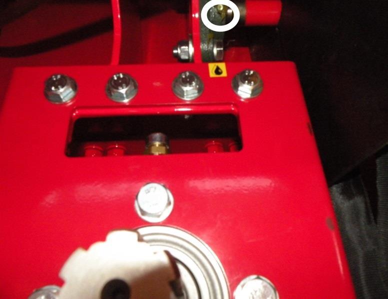

33 33 Figure 35. Figure 36. Figure 37. Figure 38. Figure 39. Figure 40.


34 34 Figure 41. Figure 42. Figure 43. Figure 44.
.")


35 Saw chain lubrication The saw chain is automatically lubricated whenever the saw bar is pressed down. In other words, the oil is pressure-fed from canister B in Figure 45 using oil pump A (Figure 45). The amount of saw chain oil can be adjusted with adjustment screw F (Figure 46). When the screw is tightened, less oil is fed to the saw chain, and vice versa. Inspection opening E in Figure 47 can be used to monitor the oil level. Oil should be added when there is approx. 5 cm of oil left in the canister. Detach the protective cover of the canister by removing locking screw D in Figure 47 and lifting the protective cover using opening C. Figure 45. Figure 46. Figure 47.


. Finally, tighten the locking screw.")
 Figure 49. 3. Relief valve of the output conveyor (85 bars) Figure 51. 4. Relief valve of the high-speed valve (accessory, 150 bars) Figure 50.")
36 Solenoid and pressure regulating valves The pressure regulating valves are adjusted to the correct settings at the factory. The firewood processor's guarantee becomes void if the factory adjustments are changed. If you need to change the adjustments, first contact the manufacturer or retailer and follow their instructions carefully. Changing the cartridge settings incorrectly may damage the machine or render it hazardous to operate. The relief valve adjustments can be changed as follows: loosen the locking nut and rotate the hex socket screw clockwise or anti-clockwise (when turning the screw clockwise, the pressure increases and vice versa). Finally, tighten the locking screw. The locations of the relief valves are indicated in the following figures. 1. Relief valve of the saw motor (190 bars) Figure Relief valve of the splitting valve (240 bars) Figure Relief valve of the output conveyor (85 bars) Figure Relief valve of the high-speed valve (accessory, 150 bars) Figure 50. Figure 48. Figure 49. Figure 50. Figure 51.
37 Washing and cleaning Loose debris and sawdust can be cleaned from the machine with pressurised air, for example. The machine can also be washed with a pressure washer, as long as the water jet is not aimed directly at the bearings or electrical equipment. Always ensure that the machine and the working area are sufficiently clean when operating the machine. The machine must always be cleaned after use. Clean the machine as necessary, and always before storing the machine for a prolonged time. After washing, the machine must be lubricated according to the instructions in Section Storage The firewood processor must be stored on a level and solid foundation. Although the machine is intended for outdoor use, it should be covered and stored in a sheltered location or indoors. Before prolonged storage, the machine must first be cleaned, then washed according to Section 4.14 and lubricated according to Section Maintenance table Target Task Daily Interval 100 h Interval 500 h Substance/accesso ry item Multiplier gearbox Check X SAE 80/90 approx. (TR model only) 1st change X 0.5 l See section Subsequent X 4.9. Hydraulic oil Check X Amount approx. 65 l Normal conditions 1st change X E.g. Teboil S 32 Subsequent X Oil filter Always CR 50 when changing oil All levers Lubrication X Lubrication oil Cutting blade Sharpen as necessary /1.5 Machine Clean Wash X Electric motor Clean X Electrical Clean X equipment Winch and strap Check X
38 5. Failures and remedial measures 5.1. Cause-effect table for failures and their removal 38 Failure Cause Remedial measure The splitting force is insufficient to split the wood. The relief valve of the splitting valve has been tightened excessively. The seal of the splitting cylinder piston is leaking. Clean and open the relief valve slightly by rotating the tightening hex socket screw (Figure 49). First ask for additional instructions from the retailer of your machine! Change the cylinder seals. The belt of the input conveyor does not move. The output conveyor does not move. The cutting motion does not fully cut the log. 1. The belt is too loose. 1. Tighten the belt in accordance with the instructions in Section 4.10 Replacing and tightening the belt of the input conveyor. 1. The belt is too loose. 2. The output conveyor's relief valve is leaking. The path of the saw bar is incorrectly adjusted. 1. Tighten the belt in accordance with the instructions in Section 4.10 Replacing and tightening the belt of the output conveyor. 2. Clean the relief valve (Figure 51) or replace it as necessary. Lower the path of the cutting flange. The saw chain does not properly sink into the wood. The machine starts but none of the functions work. The machine makes an abnormal noise. The electric motor does not start. 1. Saw chain is dull or veers to the side (due to uneven sharpness). 2.The saw bar is crooked. The electric motor runs in the wrong direction. 1. The machine makes a loud noise, but does not start. 2. The input cable is faulty. 1. Sharpen or replace the saw chain. 2. File the bar to make it straight. See Section The fuse of the transmission has burnt. Replace it. 2. Replace the cable. The motor tends to stop, and the thermal relay is easily triggered. The cutting blade does not move downwards. The thermal relay is broken or incorrectly adjusted. The machine guard is open. Contact the retailer. Close the guard.
39 Jamming of the cutting blade If the cutting blade gets jammed in the log, stop sawing and try again on another section of the log. If the cut is misaligned because the bar drags to one side, the degree of sharpness of the saw chain must be checked. A chain that is not evenly sharp will always drag towards the blunter side, which will make cutting a thick log impossible. Moreover, sawing with an evenly dull chain is inefficient, and the chain must be sharpened or replaced (see Section 4.7) Jamming of the wood on the splitting knife If a piece of wood gets jammed on the splitting knife in a situation where the splitting force is insufficient to push the piece past the knife despite several attempts to do so, do the following: 1. Restore the splitting cylinder to its initial position with reversing lever A (Figure 15). 2. Ensure that the log to be split does not exceed the maximum allowable dimensions. 3. Lift the splitting knife to the highest possible position with lever G (Figure 15) and activate the splitting. 4. If necessary, cut a sufficiently thick piece of wood (approx. 10 cm), place it into the splitting groove behind the jammed piece and activate the splitting process. The new piece will then push the jammed piece past the knife. 5. Lower the knife by approx. 5 cm and repeat step 3. Repeat step 4 until the jammed wood has passed the blade, piece by piece.
40 40 6. Connection diagram
41 41 7. Hydraulics diagram (P.T.O model)
42 42 8. Hydraulics diagram (Electric model)
43 9. Guarantee terms and declaration of conformity 43 We grant a guarantee for our machines, with the following conditions: 1. This guarantee covers defects caused by manufacturing or material failures, except for defects in components that are classified as parts that will sustain wear and tear. 2. The guarantee is valid for the original buyer, starting from the day of purchase for one (1) year, but for no more than 1,000 operating hours. 3. The guarantee becomes void if a. the instruction manual is not observed when using the machine b. the machine is used for a purpose other than that which is defined by the manufacturer c. modifications are made to the operation of the machine d. parts that are not original spare parts are used in the machine e. the maintenance procedures defined in the instructions are neglected. 4. A guarantee demand has to be issued in writing immediately upon discovery of a defect to the seller or the manufacturer. Repair under guarantee requires that the customer can reliably prove that the guarantee is valid. 5. The guarantee does not include standard adjustments, user guidance, care, maintenance or cleaning procedures. 6. Repair under guarantee requires that no attempts have been made to fix the machine or a part of it before a written notification of the defect has been issued to the seller, manufacturer or importer. 7. Only a serviceman authorised by the manufacturer or the importer is allowed to carry out a repair under guarantee. Washing, cleaning, or changing oils and fuels done while carrying out the said repair are not covered by the guarantee. 8. The repair work hours are compensated for, according to the standard rates as defined by the manufacturer. 9. The manufacturer of the machine is not liable to compensate for any travelling costs that may result from the repair work. 10. A spare part will be delivered free of charge when using the usual means intended for such parts, in accordance with the normal schedule. 11. The receiver is liable for costs occurring from special deliveries, such as express mail.
44 44 EC Declaration of Conformity for the machine (Machinery Directive 2006/42/EC, Appendix II A) Manufacturer: Maaselän Kone Oy Address: Valimotie 1, FI Haapajärvi, Finland Name and address of the person who is authorised to compile the technical file: Name: Tapio Aittokoski Valimotie 1, FI Haapajärvi, Finland The aforementioned person assures that Hakki Pilke Falcon firewood processor Serial number: is compliant with the applicable regulations of the Machinery Directive (2006/42/EC). Location and date: Haapajärvi 1 March 2014 Signature: Anssi Westerlund Managing Director
Hakki Pilke Raven 33
 ENGLISH 1 Hakki Pilke Raven 33 FIREWOOD PROCESSOR Instructions for assembly, operation and maintenance EC Declaration of Conformity Safety instructions Guarantee terms THE OPERATOR MUST READ AND UNDERSTAND
Hakki Pilke 38 Easy. The operator must read and understand these instructions before operating the log splitter!
 English 1 Hakki Pilke 38 Easy LOG SPLITTER Instructions for assembly, operation and maintenance EU Declaration of Conformity Safety instructions Warranty terms The operator must read and understand these
Hakki Pilke Falcon 35
 ENGLISH 1 / 41 Hakki Pilke Falcon 35 FIREWOOD PROCESSOR Instructions for assembly, operation and maintenance EC Declaration of Conformity Safety instructions Guarantee terms The operator must read and
1 / 47. Hakki Pilke 50 Pro. The operator must read and understand these instructions before operating the machine!
 ENGLISH 1 / 47 Hakki Pilke 50 Pro FIREWOOD PROCESSOR Instructions for assembly, operation and maintenance EC Declaration of Conformity Safety instructions Guarantee terms The operator must read and understand
Hakki Pilke. Expert 37 / Easy 37
 ENGLISH 1 Hakki Pilke Expert 37 / Easy 37 LOG SPLITTER - Instructions for assembly, operation and maintenance - EU Declaration of Conformity - Safety instructions - Warranty terms The operator must read
1 (94) HakkiPilke 42 EASY. Valimotie 1, FI Haapajärvi, Finland tel , fax
 HakkiPilke 42 EASY. Valimotie 1, FI Haapajärvi, Finland tel , fax") ENGLISH 1 (94) HakkiPilke 42 EASY LOG SPLITTER - Instructions for assembly, operation, and maintenance - EU Declaration of Conformity - Safety instructions - List of spare parts - Terms of guarantee Valimotie
ENGLISH 1 (94) HakkiPilke 42 EASY LOG SPLITTER - Instructions for assembly, operation, and maintenance - EU Declaration of Conformity - Safety instructions - List of spare parts - Terms of guarantee Valimotie
Hakki Pilke OH 27. The operator must read and understand these instructions before operating the log splitter!
 English Hakki Pilke OH 27 LOG SPLITTER Instructions for assembly, operation and maintenance EU Declaration of Conformity Safety instructions Warranty terms The operator must read and understand these instructions
Read all instructions before using the log splitter, especially safety instructions.
 Operation manual for log splitter ELH500, ELH700, ELH1100, TRH700 och TRH1100 Read all instructions before using the log splitter, especially safety instructions. Faxes Fabriks AB Hestravägen 7 330 26
Palax Lifter Hydraulic log lifter
 Instruction and Spare Parts Manual Palax Lifter Hydraulic log lifter Instructions must always be consulted before using the device PALAX Lahdentie 9 FI-61400 Ylistaro, FINLAND Tel. +358 6 4745100 Fax.
Operating and Maintenance Instructions
 !! Operating and Maintenance Instructions Keep for future reference PTO400 Log Splitter 1 Index INDEX...2 SAFETY...3 LABELS..4 QUICK GUIDE including storage and transport... 5 IN DEPTH INSTRUCTIONS...
FIREWOOD PROCESSORS.
 FIREWOOD PROCESSORS www.maaselankone.fi FIREWOOD PROCESSORS The Best Firewood Processing Technology There Is! Maaselän Kone Oy is a Finnish company with more than 30 years experience of manufacturing wood
Horizontal and Vertical. Metal Cutting Band Saw MODEL: BS-115
 Horizontal and Vertical Metal Cutting Band Saw MODEL: BS-5 SAFETY. Know your band saw. Read the operator s Manual carefully. Learn the operations, applications and limitation.. Use recommended accessories.
OXDALE PRODUCT LTD OPERATING AND MAINTENANCE MANUAL TM400 AND TM400 BIG BASE LOG SPLITTER KEEP FOR FUTURE USE
 OXDALE PRODUCT LTD OPERATING AND MAINTENANCE MANUAL TM400 AND TM400 BIG BASE LOG SPLITTER KEEP FOR FUTURE USE 1 CONTENTS Safety 3 Labels 5 Quick Guide 6 In Depth Instructions 8 Operating Instructions 12
Cutting Off Saw. Model:TV-350. Operation Manual
 Cutting Off Saw Model:TV-350 Operation Manual 1 Table of content 1. Introduction..3 1.1 General...3 1.2 Safety regulations.3 1.3 Guarantee.. 4 2. Technical data.. 4 2.1 Main groups...4 2.2 Survey and sketch
Operating Manual. for CUTTING, PERFORATING, BENDING SLB120
 Operating Manual for CUTTING, PERFORATING, BENDING SLB120 31040\B06eng 0896 0 Contents 1. Scope of delivery... 1 2. Technical specifications... 1 3. Applications... 1 4. Commissioning... 2 5. Cutting...
8 TONNE LOG SPLITTER
 8 TONNE LOG SPLITTER MODEL NO: LOGBUSTER 9 PART NO: 3402043 OPERATION & MAINTENANCE INSTRUCTIONS LS03/16 INTRODUCTION Thank you for purchasing this CLARKE 8 Tonne Log Splitter. Before attempting to use
FBX-PA-2AC. Third edition : April No
 FBX-PA-2AC Third edition : April 2006 No. 060058 INTRODUCTION Thank you very much for purchasing Kansai Special FBX series. Read and study this Instruction Manual carefully before you start any of the
VARIABLE SPEED WOOD LATHE
 MODEL MC1100B VARIABLE SPEED WOOD LATHE INSTRUCTION MANUAL Please read and fully understand the instructions in this manual before operation. Keep this manual safe for future reference. Version: 2015.02.02
Operation manual for log conveyor 100, 200 mm Read all instructions before using the log conveyor, especially safety instructions.
 Operation manual for log conveyor 100, 200 mm. Read all instructions before using the log conveyor, especially safety instructions. Faxes Fabriks AB Hestravägen 7 330 26 Burseryd Tel +46 (0)371-500 08
Tapping Screw (W/Flange) 46 Cord Armor 47 Tube (D) 48 Cord. 45 Cord Clip. Tapping Screw (W/Flange) 10 Gear Cover Ass'y. 12 Socket (B) Ass'y
 46 Cord Armor 47 Tube (D) 48 Cord. 45 Cord Clip. Tapping Screw (W/Flange) 10 Gear Cover Ass'y. 12 Socket (B) Ass'y") W8VB The exploded assembly drawing should be used only for authoized service center. W8VB Item No. Part time 1 Magnetic Hex. Socket 2 Sub Stopper 3 O-Ring (S-16) 4 Locator (A) 5 Lock Sleeve (A) 6 O-Ring
W8VB The exploded assembly drawing should be used only for authoized service center. W8VB Item No. Part time 1 Magnetic Hex. Socket 2 Sub Stopper 3 O-Ring (S-16) 4 Locator (A) 5 Lock Sleeve (A) 6 O-Ring
CHAINSAW SHARPENER MODEL: ECSS-1
 CHAINSAW SHARPENER MODEL: ECSS-1 Part No: 3402075 ASSEMBLY & INSTRUCTION MANUAL LS0409 INTRODUCTION Thank you for purchasing this CLARKE product Before attempting to use the product, it is essential that
Operating and Maintenance Instructions Keep for future reference
 Operating and Maintenance Instructions Keep for future reference TM400 Log Splitter 1 Index SAFETY... 3 LABELS.... 4 QUICK GUIDE including storage and transport... 5 IN-DEPTH INSTRUCTIONS.... 6 OPERATING
25 TONNE HYDRAULIC PRESS MODEL NO: AHP 26
 WARNING: Read these instructions before using the machine 25 TONNE HYDRAULIC PRESS MODEL NO: AHP 26 PART NO: 7615115 OPERATION & MAINTENANCE INSTRUCTIONS LS1211 INTRODUCTION Thank you for purchasing this
SERVICE MANUAL FOR HOMELOCK M1034D 2034D 1134DW 1134D
 SERVICE MANUAL FOR HOMELOCK M1034D 2034D 1134DW 1134D 11.2000 2.2012 I HOW TO USE THIS MANUAL... 1 II HOW TO ADJUST... 2 1. Height of needle bar... 2 2. Position of the lowerlooper... 3 3. Timing of the
Electric Chainsaw Sharpener
 FPP CHAINSS Electric Chainsaw Sharpener Instruction Manual For your own safety, please ensure you have read these instructions before use and have fully understood all the safety guidelines. Specifications
VARIABLE SPEED WOOD LATHE. Model DB900 INSTRUCTION MANUAL
 VARIABLE SPEED WOOD LATHE Model DB900 INSTRUCTION MANUAL 1007 TABLE OF CONTENTS SECTION...PAGE Technical data.. 1 General safety rules....1-3 Specific safety rules for wood lathe.....3 Electrical information.4
Operation Manual and Parts Book. Wessex Country Log Splitter LS100 Hydraulically Powered, Tractor Mounted. Product Code: LS100
 Operation Manual and Parts Book Wessex Country Log Splitter LS100 Hydraulically Powered, Tractor Mounted. Product Code: LS100 Manufacturers and Distributors of Quality Equipment CONTENTS 3...Welcome to
Tube Facing Tool.
 www.swagelok.com Tube Facing Tool This manual contains important information for the safe and effective operation of the Swagelok TF72 series tube facing tool. Users should read and understand its contents
CONTENTS PRECAUTIONS BEFORE STARTING OPERATION PREPARATION FOR OPERATION CAUTIONS ON USE OPERATION
 CONTENTS PRECAUTIONS BEFORE STARTING OPERATION ------------------------------------- 1 PREPARATION FOR OPERATION 1. Adjustment of needle bar stop position ---------------------------------------------------------
10 Ton LOG SPLITTER MODEL NO: Log Buster 4 PART No:
 10 Ton LOG SPLITTER MODEL NO: Log Buster 4 PART No: 3402025 OPERATION & MAINTENANCE INSTRUCTIONS 1603 ISS 4 Thank you for purchasing this CLARKE 10 ton manually operated Log Splitter. Before attempting
34 o Clipped Head Air Frame Nailer
 34 o Clipped Head Air Frame Nailer MODEL: CFN34 Part No. 3110397 OPERATING & MAINTENANCE INSTRUCTIONS 1207 SPECIFICATIONS Min. Hose Size (ID)... 6 mm (1/4 ) Ave. Air Consumption... 14.8 cfm Operating Pressure...
HOLE CUTTER SHARPENER ASSEMBLY & SERVICE MANUAL
 HOLE CUTTER SHARPENER ASSEMBLY & SERVICE MANUAL WARNING You must thoroughly read and understand this manual before operating the equipment, paying particular attention to the Warning & Safety instructions.
FBX1104P FBX1104 FBX1106P FBX1106
 FBX1104P FBX1104 FBX1106P FBX1106 Second edition : September 2004 No. 040037 INTRODUCTION Thank you for your purchasing Kansai Special's FBX Series. Read and study this instruction manual carefully before
RANGE OF PALAX FIREWOOD PROCESSORS
 COMBI M II - 3 KS 35-6 POWER 70S - 10 POWER 100S - 14 RANGE OF PALA FIREWOOD PROCESSORS Common features Discharge conveyor A common feature of all machines is the redesigned, 4,3 m long and 0,2 m wide
Policy Sponsor: Assistant Vice President Facilities Management. Responsible Unit: Trade Services
 Safe Work Instructions for Powered Mitre Cut Hack Saw (Mitercut Model 220M) Policy Sponsor: Assistant Vice President Facilities Management Responsible Unit: Trade Services Approval Date: November 2016
ULTRA CUTTER MINI SAW
 ULTRA CUTTER MINI SAW OPERATORS INSTRUCTION MANUAL Per OSHA 1926.503 it is the machine owner s responsibility to ensure that all workers using this Ultra Cutter Mini Saw are thoroughly trained in its use
SPIDA SAW OPERATIONS MANUAL
 SPIDA SAW OPERATIONS MANUAL CM SERIAL NUMBER. OCTOBER 2000 CONTENTS Page description 1.) Contents 2.) Safety First 3.) CM Overview 4.) CM Specifications 5.) CM Installation 6.) CM Operation Setting the
STARTING SERIAL NUMBER PARTS LIST FOR. Wellsaw MODEL 600 METAL CUTTING BAND SAW
 STARTING SERIAL NUMBER 11075 PARTS LIST FOR Wellsaw MODEL 600 METAL CUTTING BAND SAW Wellsaw 2829 N. Burdick, Kalamazoo, MI 49004 Phone: 269-345-1132 Fax: 269-345-0095 Rev 171005 INSTALLATION, OPERATION
ELECTRIC SLIP ROLL MACHINE. Model: ESR-1300X2.5/ESR-1300X4.5 ESR-1550X3.5/ESR-1580X2.0
 ELECTRIC SLIP ROLL MACHINE Model: ESR-1300X2.5/ESR-1300X4.5 ESR-1550X3.5/ESR-1580X2.0 Operation Manual Table of contents I MAIN SPECIFICATION...2 II SAFETY INSTRUCTIONS.. 2 III OPERATION INSTRUCTIONS..4
Hydraulic Clamp Carrier. Installation & Operation Manual
 Hydraulic Clamp Carrier Installation & Operation Manual Hydraulic Clamp Carrier Installation & Operation Manual Quick Machinery Company 8272 Peninsula Drive Kelseyville, CA 95451 phone: (707) 272-6719
OXDALE PRODUCT LTD OPERATING AND MAINTENANCE MANUAL SE400 LOG SPLITTER KEEP FOR FUTURE USE
 OXDALE PRODUCT LTD OPERATING AND MAINTENANCE MANUAL SE400 LOG SPLITTER KEEP FOR FUTURE USE 1 CONTENTS Safety 3 Labels 6 Quick Guide 7 In Depth Instructions 9 Warranty Information 16 Technical Specifications
8-Ton Manual Splitter OWNER S MANUAL
 8-Ton Manual Splitter OWNER S MANUAL WARNING: Read carefully and understand all ASSEMBLY AND OPERATION INSTRUCTIONS before operating. Failure to follow the safety rules and other basic safety precautions
Cut-Off Machine Model CC 14SE
 Cut-Off Machine Model CC 14SE Handling instructions NOTE: Before using this Electric Power Tool, carefully read through these HANDLING INSTRUCTIONS to ensure efficient, safe operation. It is recommended
 GENERAL OPERATIONAL PRECAUTIONS WARNING! When using electric tools, basic safety precautions should always be followed to reduce the risk of fire, electric shock and personal injury, including the following.
INTRODUCTION KEY TO SYMBOLS
 GRINDLUX 4000 GRINDL UX 4000 GRINDLUX 40 00 GRINDLUX 4000 GR INDLUX 4000 GRINDLU X 4000 GRINDLUX 400 0 GRINDLUX 4000 GRIN DLUX 4000 GRINDLUX 4000 GRINDLUX 4000 GRINDLUX 4000 GRIND LUX 4000 GRINDLUX 4 000
Screwfeeder Troubleshooting Guide
 Symptom General Cause Specific Cause Solution Illustration No Screws are being fed to the screwdriver Screw jam in screw delivery tubing Insufficient Screw Blast to deliver screw Adjust Screw Blast Inline
Geology, Prospectors, Mining, Metallurgy, Assaying, Environmental, Geotechnical
 LEGEND INC. Geology, Prospectors, Mining, Metallurgy, Assaying, Environmental, Geotechnical 988 Packer Way Sparks, NV 89431 Tel: (786) 786-3003 Fax: (775) 786-3613 Email: info@lmine.com Web: www.lmine.com
Hedge Trimmer Attachment HA 110 HA 850 Complément Taille-haie HA 110 HA 850 Tijeras cortasetos (suplemento) HA 110 HA 850.
 HA 110 HA 850.") Operator s manual Manual d utilisation Manual de instrucciones Hedge Trimmer Attachment HA 110 HA 850 Complément Taille-haie HA 110 HA 850 Tijeras cortasetos (suplemento) HA 110 HA 850. GB English FR ES
Operator s manual Manual d utilisation Manual de instrucciones Hedge Trimmer Attachment HA 110 HA 850 Complément Taille-haie HA 110 HA 850 Tijeras cortasetos (suplemento) HA 110 HA 850. GB English FR ES
Power Train Lift Max. Capacity: 1,250 lbs.
 655 EISENHOWER DRIVE OWATONNA, MN 55060 USA PHONE: (507) 455-7000 TECH. SERV.: (800) 533-6127 FAX: (800) 955-8329 ORDER ENTRY: (800) 533-6127 FAX: (800) 283-8665 INTERNATIONAL SALES: (507) 455-7223 FAX:
Repair manual. Fifth-wheel coupling JSK 38/50
 Repair manual Fifth-wheel coupling JSK 38/5 ZDE 199 3 12 E 6/212 1 Foreword Table of contents Page Fifth wheel couplings are connecting parts that must comply with very high safety requirements and must
Power Planer 1900B/N1900B/1902
 Power Planer 1900B N1900B 1902 SPECIFICATIONS Model 1900B/N1900B/1902 Planing width... 82 mm Planing depth... 1 mm Shiplapping depth... 9 mm No load speed (min -1 )...16,000 Overall length... 290 mm Net
Hedge Trimmer Attachment HA110 HA850 Complément Taille-haie HA110 HA850 Tijeras cortasetos (suplemento) HA110 HA850
 HA110 HA850") Operator s manual Manual d utalisation Manual de instrucciones Hedge Trimmer Attachment HA110 HA850 Complément Taille-haie HA110 HA850 Tijeras cortasetos (suplemento) HA110 HA850 GB FR ES KEY TO SYMBOLS
Operator s manual Manual d utalisation Manual de instrucciones Hedge Trimmer Attachment HA110 HA850 Complément Taille-haie HA110 HA850 Tijeras cortasetos (suplemento) HA110 HA850 GB FR ES KEY TO SYMBOLS
12mm (Max) 6mm (Max) 82mm (Max) 12mm (Max) 6mm (Max)
 6mm (Max) 82mm (Max) 12mm (Max) 6mm (Max)") 1 1 2 2 3 3 82mm (Max) 12mm (Max) 12mm (Max) 6mm (Max) 4 4 5 6 8 6mm (Max) 0.5 0mm 1 5 6 7 7 8 9 9 A = B 10 11 12 D B 1 13 14 15 0 C A D E 16 17 18 F G D B N H J G I K 19 A 20 G L 21 C K 1mm L M 1mm 22
1 1 2 2 3 3 82mm (Max) 12mm (Max) 12mm (Max) 6mm (Max) 4 4 5 6 8 6mm (Max) 0.5 0mm 1 5 6 7 7 8 9 9 A = B 10 11 12 D B 1 13 14 15 0 C A D E 16 17 18 F G D B N H J G I K 19 A 20 G L 21 C K 1mm L M 1mm 22
INSTRUCTION BOOK AND PARTS LIST
 Rag Cutter MODEL WE WARNING This machine is equipped with a very sharp knife. Keep hands, arms, and hair away from the knife area at all times. Misuse of this machine or failure to follow all safety instructions
OPERATING INSTRUCTIONS PALAX Power 100 powered by tractor powered by electricity swing conveyor of 4.3-metres with hydraulic motor
 OPERATING INSTRUCTIONS PALAX Power 100 powered by tractor powered by electricity swing conveyor of 4.3-metres with hydraulic motor SERIAL NUMBER YEAR OF MANUFACTURE Palax Lahdentie 9 FI-61400 Ylistaro,
E.C. HOPKINS LTD PGO4 PEANUT GRINDER OPERATORS MANUAL AND PARTS LIST
 E.C. HOPKINS LTD PGO4 PEANUT GRINDER OPERATORS MANUAL AND PARTS LIST E.C. HOPKINS LTD UNIT 1, 82 KETTLES WOOD DRIVE, WOODGATE BUSINESS PARK, WOODGATE VALLEY, BIRMINGHAM B32 3DB TEL NO. +44 (0)121 506 6095
Fifth-wheel coupling JSK 38/50
 Repair manual Fifth-wheel coupling JSK 38/5 ZDE 199 3 12 E 6/25 1 LT SK38C-3 English RevA Foreword Table of contents Page Fifth wheel couplings are connecting parts that must comply with very high safety
GENERAL OPERATIONAL PRECAUTIONS PRECAUTIONS ON USING CUT-OFF MACHINE
 GENERAL OPERATIONAL PRECAUTIONS WARNING! When using electric tools, basic safety precautions should always be followed to reduce the risk of fire, electric shock and personal injury, including the following.
10" Wet Tile Cutting Saw
 8035735 10" Wet Tile Cutting Saw Owner s Manual Read and understand all instructions before operation. Keep this manual for future reference pg. 2 SPECIFICATIONS ITEM DESCRIPTION Overall Dimensions (saw
JARVIS. Model25CL-4,5,6 Hock Cutter and Loin Dropper. 25CL--5 Front Legs and Horns. 25CL--4 Hind Legs and Horns. 25CL--6 Loins
 Model25CL-4,5,6 Hock Cutter and Loin Dropper 25CL--4 Hind Legs and Horns 25CL--5 Front Legs and Horns 25CL--6 Loins EQUIPMENT SELECTION... Ordering No. TABLE OF CONTENTS... Page 25CL--4... 4025007 25CL--5...
GENERAL OPERATIONAL PRECAUTIONS PRECAUTIONS ON USING DISC GRINDER
 GENERAL OPERATIONAL PRECAUTIONS WARNING! When using electric tools, basic safety precautions should always be followed to reduce the risk of fire, electric shock and personal injury, including the following.
20 Ton HYDRAULIC SHOP PRESS
 20 Ton HYDRAULIC SHOP PRESS Stock Number W41063 OWNER S MANUAL WARNING! It is the owner and/or operators responsibility to study all WARNINGS, operating, and maintenance instructions contained on the product
JARVIS. Model BR-3 Blade Reconditioner ... EQUIPMENT TABLE OF
 - Model BR-3 Blade Reconditioner EQUIPMENT SELECTION.......... Ordering No. TABLE OF CONTENTS............................ Page Model BR-3 (100 mm Blade) 115V/60Hz............ 4011003 220V/50Hz............
Core EZ. Operating Manual. Toll Free B East Broadway Avenue Tampa, FL 33619
 Operating Manual 3702 West Central Avenue Santa Ana, CA 92704 Toll Free 1-866-987-7297 11 High Street Suffield, CT 06078 www.ussaws.com 8004B East Broadway Avenue Tampa, FL 33619 Introduction This manual
WALK-BEHIND SPREADER 50 LB. CAPACITY Model 99623
 WALK-BEHIND SPREADER 50 LB. CAPACITY Model 99623 Assembly, Operating, and Maintenance Instructions Diagrams within this manual may not be drawn proportionally. Due to continuing improvements, actual product
Hedge Trimmer Attachment Complément Taille-haie Tijeras cortasetos (suplemento) Operator s manual Manual d utalisation Manual de instrucciones
 Operator s manual Manual d utalisation Manual de instrucciones") HÄcksaxtillsats HA110 HA850 Jonsered Hedge Trimmer Attachment Complément Taille-haie Tijeras cortasetos (suplemento) GB FR ES Operator s manual Manual d utalisation Manual de instrucciones KEY TO SYMBOLS
HÄcksaxtillsats HA110 HA850 Jonsered Hedge Trimmer Attachment Complément Taille-haie Tijeras cortasetos (suplemento) GB FR ES Operator s manual Manual d utalisation Manual de instrucciones KEY TO SYMBOLS
planer/thicknesser 200 x 120mm
 instructions for planer/thicknesser 200 x 120mm model no: sm1311 Thank you for purchasing a Sealey product. Manufactured to a high standard, this product will, if used according to these instructions,
7. Operating instructions: EFL 300
 7. Operating instructions: EFL 300 Copyright 2015 by Endecotts Ltd. 59 1. Setting up Technical specifications SIEVE SHAKER MODEL: EFL 300 General Information The new EFL 300 combines the best features
MODEL 83 Pail Handler
 MORSE MFG. CO., INC. 727 West Manlius Street P.O. Box 518 East Syracuse, NY 13057-0518 Phone: 315-437-8475 Fax: 315-437-1029 Email: service@morsemfgco.com Website: www.morsemfgco.com COPYRIGHT 2005 MORSE
TABLE OF CONTENTS DESCRIPTION. Safety Instructions Assembly Operation... 7
 TABLE OF CONTENTS DESCRIPTION PAGE Warranty... 1 Safety Instructions... 2 Assembly... 3 Operation... 7 #360 Grain Cleaner Drawings... 8 #360 Grain Cleaner Parts List... 10 Utility Auger Option Drawing...
Circular Saw MODEL MT581. WARNING: For your personal safety, READ and UNDERSTAND before using. SAVE THESE INSTRUCTIONS FOR FUTURE REFERENCE.
 ENGLISH Circular Saw MODEL MT58 005337 DOUBLE INSULATION I N S T R U C T I O N M A N U A L WARNING: For your personal safety, READ and UNDERSTAND before using. SAVE THESE INSTRUCTIONS FOR FUTURE REFERENCE.
3.2.3 Rear Door Window and Quarter Window Carrier Assembly
 Tighten all bolts. Tighten bolts marked -1- and -2- in specified sequence. Tightening torque: 8 Nm Remaining bolts can be tightened in any sequence. Insert door window -3- through window recess without
OPERATOR S MANUAL AND PARTS LIST 4 and 6 Ton Log Splitters - THLS-4 and THLS-6. Spares & Support:
 OPERATOR S MANUAL AND PARTS LIST 4 and 6 Ton Log Splitters - THLS-4 and THLS-6 Spares & Support: 01793 333212 www.thehandy.co.uk Before use please read & understand this manual, paying particular attention
TIN KNOCKER TK 1624 SLITTER INSTRUCTIONS & PARTS DIAGRAM. Shown with Optional Stand
 1 TIN KNOCKER TK 1624 SLITTER INSTRUCTIONS & PARTS DIAGRAM Shown with Optional Stand TAAG MACHINERY CO. (Master Distributor) 1257-B Activity Dr. Vista, CA 92081 Tel: (800) 640-0746 Fax: (760) 727-9948
Instructions for Stone Cutting Machine
 Technical data Kg. Instructions for Stone Cutting Machine SCM600 3HP 2800rpm IP55 SCM800 3HP 2800rpm IP55 SCM1000 2800rpm IP55 SCM1200 2800rpm IP55 L=600 B=85(165) L=800 B=85(175) 500x510 0 or 45 600lt/h
REPAIR INSTRUCTIONS. Cat. No Cat. No MILWAUKEE ELECTRIC TOOL CORPORATION. SDS Max Demolition Hammer. SDS Max Rotary Hammer
 Cat. No. 9-0 SDS Max Demolition Hammer Cat. No. -0 SDS Max Rotary Hammer MILWAUKEE ELECTRIC TOOL CORPORATION W. LISBON ROAD BROOKFIELD, WISCONSIN 00-0 8-9-0 d 000 8-9-0 d Special Tools Require Forcing
1. Turn off or disconnect power to unit (machine). 2. Push IN the release bar on the quick change base plate. Locking latch will pivot downward.
. 2. Push IN the release bar on the quick change base plate. Locking latch will pivot downward.") Figure 1 Miniature Quick Change Applicators, of the end feed type, are designed to crimp end feed strip terminals to prestripped wires. Each applicator is set up to accept the strip form of certain specific
Figure 1 Miniature Quick Change Applicators, of the end feed type, are designed to crimp end feed strip terminals to prestripped wires. Each applicator is set up to accept the strip form of certain specific
SAFETY AND OPERATING MANUAL
 SAFETY AND OPERATING MANUAL BladeRunner X2 WX572 9 10 8 11 5 7 12 6 20 1 2 4 3 14 13 15 A2 A1 17 18 B2 B1 1 2 1 2 19 B3 3 4 2 C 1 D1 D1 C 2 1 E1 D2 1 2 E2 1 2 F G1 G1 F OFF ON G2 G3 H1 H2 I1 I2 I1 I2 J
UNIVERSAL WORKSTATION
 ASSEMBLY AND OPERATING INSTRUCTIONS UNIVERSAL WORKSTATION FOX Model F50-179 1 Universal Workstation FOX MODEL F50-179 TABLE OF CONTENTS Safety instructions Page 3 Specific safety instructions for workbenches..
DL5000 INSTRUCTION MANUAL. DIAMOND TECH Innovations For Creativity DL 5000 DIAMOND LASER BAND SAW OPERATIONS MANUAL
 DIAMOND TECH Innovations For Creativity DL 5000 DIAMOND LASER BAND SAW OPERATIONS MANUAL - PAGE 1 Before You Begin Read and follow all instructions carefully. After unpacking all components, assemble band
Impact Wrench MODEL TW1000. WARNING: For your personal safety, READ and UNDERSTAND before using. SAVE THESE INSTRUCTIONS FOR FUTURE REFERENCE.
 ENGLISH Impact Wrench MODEL TW000 00605 DOUBLE INSULATION I N S T R U C T I O N M A N U A L WARNING: For your personal safety, READ and UNDERSTAND before using. SAVE THESE INSTRUCTIONS FOR FUTURE REFERENCE.
ABM International, Inc. Navigator Assembly Manual
 ABM International, Inc. 1 1.0: Parts List Tablet (Qty. 1) Tablet mount (Qty. 1) NOTE: Mount may appear and operate different then image below Control Box (Qty. 1) Motor Power Supply (Qty. 1) 2 X-axis motor
Lumber Smith. Assembly Manual. If you are having problems assembling the saw and need assistance, please contact us at:
 Lumber Smith Assembly Manual If you are having problems assembling the saw and need assistance, please contact us at: 804-577-7398 info@lumbersmith.com 1 Step 1 Safety Carefully read the Owners Manual.
WX8800 WX8700 LX5801 WX8842 WX MC30
 WX8800 WX8700 LX5801 WX8842 WX8842-1 MC30 First published : August 1991 Third edition : August 2004 No. 040037 INTRODUCTION Thank you for your purchasing Kansai Special's WX Series. Read and study this
MANUAL PLASTIC STRAPPING TOOL MODEL P404
 OPERATION MANUAL / SPARE PARTS LIST MANUAL PLASTIC STRAPPING TOOL MODEL P404 43.0404.02 43040402.en/MAS/ 12.05 INDEX PAGE 1 SAFETY INSTRUCTIONS 2 2 TECHNICAL DATA 3 3 OPERATION ELEMENTS 4 4 ADJUSTMENT
Band-Master ATS Nano Pneumatic Banding Tool Operating Instructions
 Band-Master ATS 601-118 Nano Pneumatic Banding Tool CONTENTS 601-118 Overview... 3 Safety.... 5 Initial Tool Set-up... 5 Regulator assembly mounting... 5 Attach tool head to regulator.... 6 Operating instructions...
SHOP PRESS ASSEMBLY INSTRUCTIONS
 SHOP PRESS ASSEMBLY INSTRUCTIONS CP403-40 TON ELECTRIC PRODUCTION PRESS CP405-50 TON ELECTRIC PRODUCTION PRESS WITH WINCH PRESS SPECIFICATIONS Arcan Model No. A B C D E F G H I J K L CP403 74" 32" 29.75"
C-1650P 16 Gauge, 1/2 Medium Crown Stapler
 C-1650P 16 Gauge, 1/2 Medium Crown Stapler MANUAL/WARNING: IMPORTANT PLEASE READ BEFORE USING TOOL Please read the following operating instructions manual. Refer to this manual for safety, adjustment and
Veto spring agitator / kw burner heads
 7.2004/2 Enclosure for Veto Chip Matic/ Veto Chip Matic Maxi instruction manual. Veto spring agitator / 160 640 kw burner heads Instruction manual Manufacturer ALA TALKKARI Veljekset Ala-Talkkari Oy Fin-62130
x 43 Wood Lathe
 Please dispose of packaging for the product in a responsible manner. It is suitable for recycling. Help to protect the environment, take the packaging to the local amenity tip and place into the appropriate
Impact Wrench MODEL 6905B MODEL 6906
 ENGLISH Impact Wrench MODEL 6905B MODEL 6906 005305 DOUBLE INSULATION I N S T R U C T I O N M A N U A L WARNING: For your personal safety, READ and UNDERSTAND before using. SAVE THESE INSTRUCTIONS FOR
Agricultural Mechanics and Technology Power Tool Safety Rules
 Agricultural Mechanics and Technology Power Tool Safety Rules Name: BAND SAW Use: Cutting curves, circles and irregular shapes. 1. Use clean SHARP blades. 2. The teeth should always point DOWN. 3. Adjust
ATD AMP Variable Speed Reciprocating Saw Owner s Manual
 ATD-10535 7 AMP Variable Speed Reciprocating Saw Owner s Manual Manufactured in China To ATD Tools, Inc. Specifications TECHNICAL SPECIFICATIONS Voltage: 120V Frequency: 60Hz Power input: 7 Amps No load
Cottage Style Dock Instructions
 Cottage Style Dock Instructions Table of Contents 1. Dock Assembly and Set-Up 1.1 Quick Start 1.2 Positioning Quick Clips 1.3 Installing Dock Legs 1.4 Installing Foot Pads 1.5 Installing Cross Braces 1.6
ELECTRIC TOOL CORPORATION
 Cat. No. -0 / Hex Demolition Hammer Cat. No. 0-0 Spline Rotary Hammer MILWAUKEE ELECTRIC TOOL CORPORATION W. LISBON ROAD BROOKFIELD, WISCONSIN 00-0 -9-00 d 000 -9-00 d SpecialTools Require Forcing discs
ULTRA CUTTER PRO OPERATORS INSTRUCTION MANUAL. This manual covers all models 9, 11 and 13 HP
 ULTRA CUTTER PRO OPERATORS INSTRUCTION MANUAL This manual covers all models 9, 11 and 13 HP Per OSHA 1926.503 it is the machine owner s responsibility to ensure that all workers using this Ultra Cutter
GEARED HEAD DRILL / MILL MACHINE INSTRUCTION MANUAL
 www.industrialtool.com.au GEARED HEAD DRILL / MILL MACHINE INSTRUCTION MANUAL READ CAREFULLY AND UNDERSTAND THESE INSTRUCTIONS BEFORE USE. LIMITED WARRANTY Industrial Tool & Machinery Sales (hereinafter
Operation Manual Model #
 3-Point Hitch Vertical/Horizontal Log Splitter Operation Manual Model # 100450 This safety alert symbol identifies important safety messages in this manual. Failure to follow this important safety information
SERVICE MANUAL PARTS LIST MODEL: NH40
 SERVICE MANUAL & PARTS LIST MODEL: NH40 CONTENTS What to do when... 1-3 SERVICE ACCESS Face Cover... 4 Bed Cover... 5 Free-arm Cover... 6 Front Cover... 7 Rear Cover... 8 MECHANICAL ADJUSTMENT Presser
C a r r i a g e A s s e m b l y R e p l a c e m e n t
 E1 TF-CR C a r r i a g e A s s e m b l y R e p l a c e m e n t October 2007 Software Version 5.0 and higher IMPORTANT! TigerStop must be enabled with a code that must be obtained from TigerStop Customer