The legal validity of this report can only be claimed on presentation of the complete report.
|
|
|
- Loraine Rose
- 5 years ago
- Views:
Transcription

1
2 Contents Page No 1 Introduction General Description of Construction Leaf Sizes Configurations Leaf Size Adjustment Overpanels Fanlights and Side Screens Glazing Door Frames Edging Materials Leaf Facing Materials Intumescent Materials Adhesives Tested Hardware Additional & Alternative Hardware Classification of Timber Door Gaps Structural Opening Fixings Sealing to Structural Opening Insulation Smoke Control Conclusion Declaration by the Applicant Limitations Validity Appendix A ; Performance Data Appendix B ; Steel Door Frames Appendix C ; Glazing Systems Appendix D ; Revisions Appendix E ; Data Sheets Ref: Chilt/A12151 Page 2 of 68
3 1 Introduction This document constitutes a global assessment to collate the fire resistance evidence for Blankfort Inc., Blankfort 30 and Blankfort 30+ fire resisting doorsets. The assessment uses established extrapolation and interpretation techniques in order to extend the scope of application by determining the limits for the design based on the tested constructions and performances obtained. The assessment is an evaluation of the potential fire resistance performance, if the elements were to be tested in accordance with BS 476: Part 22: General Description of Construction 2.1 Blankfort 30 The primary construction for Blankfort 30 door leaves covered by this assessment comprises the following designs: Core: Element Species/type Dimensions (mm) (lamels of one of the following tested species) Top rail (leaves over 2150mm high) Facings Eastern white pine Grey pine Spruce Same material as core Chipboard (particleboard) Lamel size: max 42 wide x thick Lamel size: max 42 wide x thick Lamel size: max 42 wide x thick Density (kg/m 3 ) 450* 500* * 100 wide As core 9 thick 650* Lippings: Hardwood Minimum 6 thick 582 *Stated nominal density Note: The design may also be produced in 50654mm thick versions as required, providing adjustment is made to the core thickness. Ref: Chilt/A12151 Page 3 of 68
4 2.2 Blankfort 30+ The primary construction for Blankfort 30+ door leaves covered by this assessment comprises the following designs: Core: Element Species/type Dimensions (mm) (lamels of one of the following tested species) Top rail (leaves over 2150mm high) Outer Facings Inner Eastern white pine Grey pine Spruce Same material as core Lamel size: max 30 wide x 21 thick Lamel size: max 30 wide x 21 thick Lamel size: max 30 wide x 21 thick Density (kg/m 3 ) 450* 500* * 100 wide As core MDF 3 thick 700* Chipboard (particleboard) 9 thick 650* Lippings: Hardwood Minimum 6 thick 582 * Stated nominal density Note: The design may also be produced in 50654mm thick versions as required, providing adjustment is made to the core thickness. 3 Leaf Sizes Assessment for increased leaf dimensions is based on the design s performance and the characteristics exhibited during test. Data sheets specifying the maximum assessed leaf sizes and graphs showing the permitted gradient between maximum height and width are contained in appendix E. Doorsets containing leaves with smaller dimensions than those stated are deemed to be less onerous and are therefore automatically covered. Ref: Chilt/A12151 Page 4 of 68
5 4 Configurations Based on the test evidence listed in appendix A, this assessment covers the following doorset configurations: Abbreviation LSASD & ULSASD DASD LSASD+OP & ULSASD+OP DASD+OP LSADD & ULSADD DADD LSADD+OP & ULSADD+OP DADD+OP Description Latched & unlatched single acting single doorset Double acting single doorset Latched & unlatched single acting single doorset with overpanel Double acting single doorset with overpanel Latched & unlatched single acting double doorset Double acting double doorset Latched & unlatched single acting double doorset with overpanel Double acting double doorset with overpanel Unequal leaf double doorsets are covered by this assessment with no restriction on the smaller leaf dimension. 5 Leaf Size Adjustment Door leaves of this design may be altered as follows: Element Leaf Lipping Reduction The manufactured size of the leaf may be reduced in height or width without restriction but reduction in height must be from the bottom edge only with the top rail dimension (where present) remaining unaltered. The dimensions stated in section 10 may be reduced by 20% for fitting purposes. If reductions in leaf width or height are made, lippings must be replaced and bonded correctly to maintain the minimum specified lipping dimensions. 6 Overpanels Overpanels of the same construction as the door leaves may be used either flush with the leaf heads or when separated by a transom. In either case the overpanel must be fully contained within the door frame (see following diagram). If a transom is required to separate the leaf heads from the overpanel, it must be to the same specification as the door frame (see the note under the table in section 9.1). Door frame joints must utilise one of the following four methods: mortise and tenon joints; half lapped joints; mitre joints; butt joints (see section 9.2). Ref: Chilt/A12151 Page 5 of 68


6 All methods require joints to be tight, with no gaps, and require mechanical fixing with the appropriate size ring shank nails or screws. Butt joints must be additionally bonded with urea formaldehyde or equivalent. Overpanels must be fixed by: Screwing through the rear of the frame with steel screws passing at least 30mm into the centre line of the overpanel. Fixings must be no more than 100mm from each corner and a maximum of 250mm centres in between. Maximum overpanel heights are as follows: Single doorsets mm; Double doorsets mm. The intumescent seals specified for the jambs in appendix E, must be fitted in the concealed edges of the overpanel or frame reveal. Providing the intumescent seals are fitted to all edges of the overpanel, the frame to overpanel junction is permitted to have a maximum 2mm gap tolerance. The intumescent seal specification for flush overpanel assemblies (junction between leaf heads and overpanel) must comply with the details given in appendix E. Overpanel fixings Intumescent seals Transom Leaf head 7 Fanlights and Side Screens 7.1 General Timber frame doorsets may include glazed fanlights or side screens. The timber frame and glazing beads must be hardwood with a minimum density of 640 kg/m 3, whilst the frame section must be a minimum of 70mm x 44mm. The door frame and screen construction must comply with the specification contained in section 9. The maximum assessed fanlight and side screen dimensions are detailed in the table below, subject to the following restriction: The glazing system and glass must be able to demonstrate adequate performance when tested as a window or screen in accordance with BS 476: Part 22: 1987 or BS EN : 2000 or 2008, at the pane dimensions to be installed. Ref: Chilt/A12151 Page 6 of 68

.")

7 Screen Element Configuration Height (mm) Width (mm) Fanlight Side screen Single & double doorsets Single & double doorsets 600 Overall door height Overall door width 600 NB: MDF and softwood frame doorsets are not assessed for glazed fanlights or side screens without specific test evidence (see section 7.2 for options). Bead fixings Assessed glass type Glazing seal Transom Leaf head Note: Drawing is representative of doorset construction only, actual construction must be as the text within this document specifies. Ref: Chilt/A12151 Page 7 of 68
8 7.2 Common frame sections The following drawings depict possible constructions of common frame sections for the screens and door frame jambs: Option 1 6 One frame section Door leaf Glazed screen element Option 2 6 Back to back frame section Option 3 6 Back to back frame section with separating post When using separate sections of timber, as shown above (option 2 and 3), each section must be suitably fixed to one another using appropriate steel screw fixings and glued using one of the adhesives approved for the lipping in the adhesive section of this report. Screws must be fixed at 600mm centres and locate to approx 2/3 depth of the adjacent timber section. The overall frame section and material must match that given in this assessment for each glass type and glazing specification. Joints must be tight with no gaps. It is permitted to include maximum 3mm (w) x 3mm (d) quirks at the junction of each timber section for option 2 and 3. Drawing is representative of each type of common frame member, actual construction in terms of intumescent seal location and material etc. must be as the text within this document specifies. Ref: Chilt/A12151 Page 8 of 68
9 7.3 Screen elevations The following drawing depicts a possible door and glazed screen configuration. The diagram is for information only. All details to remain as specified herein. Fanlight Transom Common frame section for side screens and door frame jamb Mullions Side screens Glazed Blankfort 30 or Blankfort Specific Glass Types The following sections provide a scope of approval for different glass types when used for glazing fanlights or side screens. Fanlights may be used in conjunction with side screens subject to the specification given for each of the glass types. Unless stated in the following sections, all construction details for the doorset must remain as specified in the main assessment. Ref: Chilt/A12151 Page 9 of 68
10 7.4.1 EW30 (7mm thick) CGI Ltd Transom/mullion details: Minimum 75mm deep x 40mm thick softwood or hardwood (min density 510kg/m 3 ). This timber section can be used for both door jambs and transoms above doors included within screens and for the perimeter framing of the screen and the transoms and mullions separating individual panes of glass within the fanlights and side screens. Glazing details: 15mm high x 32mm deep hardwood beads (minimum density 640kg/m 3 ). The bead shape may be square or incorporate a o chamfer; 50mm long size 668 steel wood screws at maximum of 70mm from corners and 200mm centres inserted at 30 o to the plane of the glass; 10mm x 2mm Interdens located between the glass and the beads; 5mm high x 7mm wide x 40mm long hardwood or non6combustible setting blocks with 5mm expansion allowance to all edges. Maximum single pane dimensions: Screen Element Height (mm) Width (mm) Fanlight Side screen The pane dimensions given above represent the maximum permitted width against maximum permitted height. Panes with smaller dimensions are acceptable; Transoms supporting single panes above 900mm wide must be centrally supported by at least one vertical mullion. Multiple panes: The fanlights and side screens may comprise multiple panes of glass providing the total doorset and screen assembly does not exceed 2950mm high and the transom/mullion restrictions above are complied with. Leaf configurations and screen dimensions: The total width of the screen assembly is unlimited; The screen assembly may only contain 1 No. single or double leaf doorset. Ref: Chilt/A12151 Page 10 of 68
11 7.4.2 EW30 Maxi (11mm thick) CGI Ltd Transom/mullion details: Minimum 75mm deep x 40mm thick hardwood (min density 640kg/m 3 ). This timber section can be used for both door jambs and transoms above doors included within screens and for the perimeter framing of the screen and the transoms and mullions separating individual panes of glass within the fanlights and side screens. Glazing details: 20mm high x 30mm deep hardwood beads (minimum density 640kg/m 3 ). The bead shape may be square or incorporate a o chamfer; 50mm long size 668 steel wood screws at maximum of 70mm from corners and 200mm centres inserted at 30 o to the plane of the glass; 10mm x 2mm Interdens located between the glass and the beads; 5mm high x 11mm wide x 40mm long hardwood or non6combustible setting blocks with 5mm expansion allowance to all edges. Maximum single pane dimensions: Screen Element Height (mm) Width (mm) Fanlight Side screen The pane dimensions given above represent the maximum width against maximum height. Panes with smaller dimensions are acceptable. Multiple panes: The fanlights and side screens may comprise multiple panes of glass providing the total doorset and screen assembly does not exceed 2950mm high and the transom/ mullion restrictions above are complied with. Leaf configurations and screen dimensions: The total width of the screen assembly is unlimited; The screen assembly may only contain 1 No. single or double leaf doorset. Ref: Chilt/A12151 Page 11 of 68
12 7.4.3 EI30 (15mm thick) CGI Ltd Transom/mullion details: Minimum 80mm deep x 40mm thick hardwood (min density 640kg/m 3 ). This timber section can be used for both door jambs and transoms above doors included within screens and for the perimeter framing of the screen and the transoms and mullions separating individual panes of glass within the fanlights and side screens. Glazing details: 20mm high x 23mm deep hardwood beads (minimum density 640kg/m 3 ). The bead shape may be square or incorporate a o chamfer; 50mm long size 668 steel wood screws at maximum of 70mm from corners and 200mm centres inserted at 30 o to the plane of the glass; 7mm x 2mm Egopren glazing tape located between the glass and the beads; 15mm x 2mm Kerafix Pan 200 edge seal fitted around edge of glass; 3mm high x 15mm wide x 80mm long hardwood or non6combustible setting blocks with 5mm expansion allowance to all edges. Maximum single pane dimensions: Screen Element Height (mm) Width (mm) Fanlight Side screen The pane dimensions given above represent the maximum width against maximum height. Panes with smaller dimensions are acceptable; Transoms supporting single panes above 1100mm wide must be centrally supported by at least one vertical mullion. Multiple panes: The fanlights and side screens may comprise multiple panes of glass providing the total doorset and screen assembly does not exceed 2950mm high and the transom/ mullion restrictions above are complied with. Leaf configurations and screen dimensions: The total width of the screen assembly is unlimited; The screen assembly may only contain 1 No. single or double leaf doorset. Ref: Chilt/A12151 Page 12 of 68
13 mm Pyranova Schott Transom/mullion details: Minimum 68mm deep x 80mm thick softwood or hardwood (min density 400kg/m 3 ). This section must be used for door jambs and transom above head of door leaves; Minimum 68mm deep x 40mm thick softwood or hardwood (min density 400kg/m 3 ) can be used for the perimeter framing of the screen and the transoms and mullions separating individual panes of glass within the fanlights and side screens. Glazing details: 20mm high x 23.5mm deep hardwood beads (minimum density 640kg/m 3 ). The bead shape may be square or incorporate a o chamfer; 40mm long size 668 steel wood screws at maximum of 70mm from corners and 200mm centres inserted at 30 o to the plane of the glass; 8mm x 3mm closed cell foam glazing tape located between the glass and the beads; 3mm high x 15mm wide x 80mm long hardwood or non6combustible setting blocks. Maximum single pane dimensions: Screen Element Height (mm) Width (mm) Fanlight Side screen The pane dimensions given above represent the maximum width against maximum height. Panes with smaller dimensions are acceptable; Transoms supporting single panes above 1100mm wide must be centrally supported by at least one vertical mullion. Multiple panes: The fanlights and side screens may comprise multiple panes of glass providing the total doorset and screen assembly does not exceed 2950mm high and the transom/ mullion restrictions above are complied with. Leaf configurations and screen dimensions: The total width of the screen assembly is unlimited; The screen assembly may only contain 1 no. single or double leaf doorset. Ref: Chilt/A12151 Page 13 of 68
14 mm Pyroshield 2 Pilkington Glass Transom/mullion details Minimum 80mm deep x 44mm thick softwood or hardwood (min density 510kg/m 3 ). This timber section can be used for both door jambs and transoms above doors included within screens and for the perimeter framing of the screen and the transoms and mullions separating individual panes of glass within the fanlights and side screens. Glazing details: 15mm high x 20mm deep hardwood beads (minimum density 640kg/m³) with an 18º chamfer; 40mm long size 668 steel wood screws at maximum of 50mm from corners and 150mm centres inserted at 45 to the glass; 10mm x 2mm Interdens located between the glass and the beads; 3mm high x 6mm wide x 40mm long hardwood or non6combustible setting blocks fitted at 300mm centres along bottom edge of glass with 3mm expansion allowance to all edges. Maximum single pane dimensions: Screen Element Height (mm) Width (mm) Fanlight Side screen The pane dimensions given above represent the maximum permitted width against maximum permitted height. Panes with smaller dimensions are acceptable. Multiple panes: The fanlights and side screens may comprise multiple panes of glass providing the total doorset and screen assembly does not exceed 2950mm high and the transom/ mullion restrictions above are complied with. Leaf configurations and screen dimensions: The total width of the screen assembly is unlimited; The screen assembly may only contain 1 No. single or double leaf doorset. Ref: Chilt/A12151 Page 14 of 68
15 mm Pyrodur 30;104 Pilkington Glass Transom/mullion details: Minimum 80mm deep x 44mm thick hardwood (min density 640kg/m 3 ). This timber section can be used for both door jambs and transoms above doors included within screens and for the perimeter framing of the screen and the transoms and mullions separating individual panes of glass within the fanlights and side screens. Glazing details: 20mm high x 20mm deep hardwood beads (minimum density 640kg/m³) with an 15º chamfer; 40mm long size 668 steel wood screws at maximum of 50mm from corners and 150mm centres inserted at 30 to the glass; 20mm x 2mm Interdens located between the glass and the beads; 3mm high x 6mm wide x 40mm long hardwood or non6combustible setting blocks fitted at 300mm centres along bottom edge of glass with 3mm expansion allowance to all edges. Maximum single pane dimensions: Screen Element Height (mm) Width (mm) Fanlight Side screen The pane dimensions given above represent the maximum permitted width against maximum permitted height. Panes with smaller dimensions are acceptable. Multiple panes: The fanlights and side screens may comprise multiple panes of glass providing the total doorset and screen assembly does not exceed 2950mm high and the transom/ mullion restrictions above are complied with. Leaf configurations and screen dimensions: The total width of the screen assembly is unlimited; The screen assembly may only contain 1 No. single or double leaf doorset. Ref: Chilt/A12151 Page 15 of 68
16 mm Pyrodur 60;10 Pilkington Glass Transom/mullion details: Minimum 80mm deep x 44mm thick hardwood (min density 640kg/m 3 ). This timber section can be used for both door jambs and transoms above doors included within screens and for the perimeter framing of the screen and the transoms and mullions separating individual panes of glass within the fanlights and side screens. Glazing details: 20mm high x 20mm deep hardwood beads (minimum density 640kg/m³) with an 15º chamfer; 40mm long size 668 steel wood screws at maximum of 50mm from corners and 150mm centres inserted at 30 to the glass; 20mm x 2mm Interdens located between the glass and the beads; 3mm high x 6mm wide x 40mm long hardwood or non6combustible setting blocks fitted at 300mm centres along bottom edge of glass with 3mm expansion allowance to all edges. Maximum single pane dimensions: Screen Element Height (mm) Width (mm) Fanlight Side screen The pane dimensions given above represent the maximum permitted width against maximum permitted height. Panes with smaller dimensions are acceptable. Multiple panes: The fanlights and side screens may comprise multiple panes of glass providing the total doorset and screen assembly does not exceed 2950mm high and the transom/ mullion restrictions above are complied with. Leaf configurations and screen dimensions: The total width of the screen assembly is unlimited; The screen assembly may only contain 1 No. single or double leaf doorset. Ref: Chilt/A12151 Page 16 of 68
17 mm Pyrostop 30;10 Pilkington Glass Transom/mullion details: Minimum 95mm deep x 44mm thick hardwood (min density 640kg/m 3 ). This timber section can be used for both door jambs and transoms above doors included within screens and for the perimeter framing of the screen and the transoms and mullions separating individual panes of glass within the fanlights and side screens. Glazing details: 20mm high x 37mm deep hardwood beads (minimum density 640kg/m3). Can be square or chamfered; 60mm long size 668 steel wood screws at maximum of 50mm from corners and 150mm centres inserted at 45 to the glass; 12mm x 3mm Hodgsons Sealants Firestrip 30 located between the glass and the beads; 5mm high x 15mm wide x 40mm long hardwood or non6combustible setting blocks fitted at 300mm centres along bottom edge of glass with 5mm expansion allowance to all edges. Maximum single pane dimensions: Screen Element Height (mm) Width (mm) Fanlight Side screen The pane dimensions given above represent the maximum permitted width against maximum permitted height. Panes with smaller dimensions are acceptable. Multiple panes: The fanlights and side screens may comprise multiple panes of glass providing the total doorset and screen assembly does not exceed 2950mm high and the transom/ mullion restrictions above are complied with. Leaf configurations and screen dimensions: The total width of the screen assembly is unlimited; The screen assembly may only contain 1 No. single or double leaf doorset. Ref: Chilt/A12151 Page 17 of 68
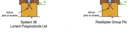
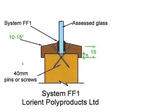
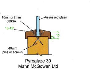
18 8 Glazing 8.1 General The doorset design has demonstrated that it is capable of tolerating glazed apertures, whilst providing a margin of over performance. The maximum total assessed glazed area is 1.92m 2, which may be distributed using multiple panes, with a maximum single pane area of 1.32m 2. Glazing is acceptable within the following parameters. 8.2 Assessed Glazing Systems The glazing system may be as tested, or alternatively one of the following tested proprietary systems: Glazing System Manufacturer 1. Therm6A6Strip 30 Intumescent Seals Ltd. 2. Therm6A6Glaze 45 Intumescent Seals Ltd. 3. Fireglaze 30 Sealmaster Ltd. 4. Firestrip 30 Hodgsons Sealants Ltd. 5. Pyroglaze 30 Mann McGowan Ltd. 6. System 36 Lorient Polyproducts Ltd. 7. FF1 Lorient Polyproducts Ltd. 8. R8913 Pyroplex Ref: Chilt/A12151 Page 18 of 68
19 8.3 Assessed Glass Products Assessed glass types are as follows: Glass Type Manufacturer Thickness (mm) Max Area (m 2 ) 1. Fivestar (see note 2) Vetrotech Saint Gobain Pyroshield Pilkington Group Ltd. 6 & Pyroshield 2 Pilkington Group Ltd. 6 & Pyroswiss Classic (see note 2) Vetrotech Saint Gobain Pyran S Schott Glass Ltd Pyrostem CGI Ltd Pyroguard EW 30 CGI Ltd Pyranova S3.07 Schott UK Ltd Pyrobelite 7 AGC Flat Glass UK Pyrodur Pilkington Group Ltd Pyrodur Pilkington Group Ltd Pyroguard EW MAXI CGI Ltd Pyranova 156S2.0 Schott UK Ltd Pyrobelite 12 AGC Flat Glass UK Pyrodur Pilkington Group Ltd Swissflam Lite Vetrotech Saint Gobain AG Pyroguard EI 30 CGI Ltd Pyrostop Pilkington Group Ltd Pyrobel 16 AGC Flat Glass UK Notes: 1. All glass types must be fitted strictly in accordance with the manufacturers' tested details/installation requirements, particularly with reference to suitable tolerances for expansion of the glass pane. 2. 6mm Pyroswiss and Fivestar manufactured by Vetrotech may only be used with glazing system 3 (Firestrip 30) listed in section Glass types 12 and are fully insulating for 30 minutes in terms of the criteria set out in BS 476: Part 20: Ref: Chilt/A12151 Page 19 of 68
20 8.4 Glazing beads and Installation Glazing beads must be from hardwood as specified in the following table: Material Profile Min Density (kg/m³) Application Hardwood Splayed 640 All proprietary systems detailed in section 8.2 and all glass types listed in section 8.3 Hardwood Square 640 All proprietary systems detailed in section 8.2 with glass types 9619 listed in section 8.3 An alternative to the proprietary splayed bead systems is a square hardwood bead which may be used either with or without a 3mm high x 3mm deep quirk (see appendix B for diagram of profile). Square beads may only be used with glass types 9619, and with all proprietary systems listed in section 8.2. The shape of glazed apertures is not restricted providing the glazing system can accommodate the profile. Glazed apertures must not be nearer than 100mm to any leaf edge. Multiple apertures are acceptable up to the maximum approved area with a minimum dimension of 80mm separating the apertures. All timber for glazing beads must be joinery quality straight grained and free from splits, checks and knots. Glazing beads must be retained in position with 40mm long x 2mm diameter steel pins or 40mm long No 8 screws, inserted at 35640º to the vertical at no more than 50mm from each corner and at 150mm maximum centres. False timber beads may be applied to glass types 9611 and using one of the following intumescent glazing products: Glazing System Manufacturer 1. Therm6A6Strip 30 Intumescent Seals Ltd. 2. Fireglaze 30 Sealmaster Ltd. 3. Firestrip 30 Hodgson Sealants Ltd. 4. Envirograf Product 77 6 G10/10 Intumescent Systems Ltd. 5. Intumescent mastic or silicone tested for glazing applications to BS 476: Part 22: 1987 or BS EN : 2000 or 2008 Various Seals for false glazing beads must be a minimum of 10mm wide x mm thick. Preformed strip systems 164 may be self adhesive and grooved into the rear of the glazing bars. Sectional drawings detailing the proprietary glazing systems are contained in appendix C. Ref: Chilt/A12151 Page 20 of 68
: Material Section Size (mm) Min Density (kg/m³)")
21 9 Door Frames 9.1 Door Frame Construction Door frames for Blankfort 30 and Blankfort 30+ may be timber or MDF as follows (for steel door frame option see appendix B): Material Section Size (mm) Min Density (kg/m³) Application Leaf Size Range (mm) Softwood/ hardwood* 70 x Not permitted with flush overpanel See appendix E Hardwood* 70 x All All MDF 70 x All See appendix E *If the doorset features a transomed overpanel (i.e. constructed using a section of door blank), the door frame must be softwood or hardwood with a minimum section of 70mm x 32mm and of the minimum densities stated above. Framing for doorsets with side screens and fanlights must meet the relevant specification in section 7. All door frame timber must be to class J30 as specified in BS EN 942: 2007 (see section 16). A 12mm deep planted stop is adequate for single acting frames whilst double acting frames may be scalloped or square (see diagram below). Frame joints may be mortice and tenoned, mitred, half lapped or butted and with no gaps (see section 9.2). All jointing methods require mechanical fixing with the appropriate size ring shank nails or screws. The following diagram depicts the assessed frame profiles and dimensions: A = min 70mm B = min mm (see table above) C = min 12mm R = radius from floor spring 8mm max radius to create a maximum 2mm edge profiling Standard Scalloped Profiled edges Ref: Chilt/A12151 Page 21 of 68
22 9.2 Door Frame Joints Half Lapped Joint Mitre Joint Mortise and Tenon Joint Butt Joint Note: Drawing is representative of each type of door frame joint, actual construction in terms of intumescent seal location and material etc. must be as the text within this document specifies. Ref: Chilt/A12151 Page 22 of 68
23 9.3 Door frame installations The following diagrams indicate acceptable and unacceptable door frame installations: Max 10 x 10mm shadow gap with 2mm intumescent mastic capping or 10 x 4mm PVC encased intumescent seal 15mm 6 to 10mm Permitted Permitted Permitted Not Permitted Not Permitted Permitted 10 Edging Materials 10.1 Timber Lippings Blankfort 30 and 30+ designs must be lipped in accordance with the following specification: Material Size (mm) Min Density (kg/m³) Timber for lippings must be straight grained joinery quality hardwood, free from knots splits or checks 1. Flat = 6mm to 16mm thick with a maximum of 2mm profiling permitted at corners of lipping (see section 9.1) 2. Rounded = 8mm618mm with a radius matching the distance between leaf edge and floor pivot (see section 9.1) 3. Rebated = 18mm to 28mm thick with a 12mm deep rebate (equal or offset) 582 Notes: 1. Single doorsets are not permitted with rebated vertical edges; 2. Single & double doorsets without overpanels only require lipping on the vertical edges; 3. Doorsets with flush overpanels (i.e. no transom) must be lipped on the vertical edges and additionally at the bottom edge of the overpanel and top edge of the doors; Ref: Chilt/A12151 Page 23 of 68
24 4. Doorsets with flush overpanels may have the head junctions and meeting edges rebated concurrently; 5. Lippings for concealed intumescent material must be bonded with urea formaldehyde; 6. If a leaf head junction or meeting edge detail is to incorporate an offset rebate, the specified rebated intumescent detail must be used (see appendix E) with a minimum of 3mm from the edge of the intumescent strip to the leaf edge being maintained. The intumescent may be positioned closer to the upstand in order to achieve this requirement; 7. A chamfer is permitted to the lipping at the leading edge of leaves providing the door gaps meet the requirements of section PVC Edge Protectors It is possible to fit proprietary edge protectors to this doorset design providing they have suitable supporting test evidence to BS 476: Part 22: 1987 or BS EN : 2000 or 2008, when fitted to timber doorsets of similar construction to this design. The end user must satisfy themselves that the test evidence supports the proposed end use application. Construction Specialities UK Ltd can provide edge protectors with supporting test evidence for this doorset design and must be contacted to confirm exact requirements ( 11 Leaf Facing Materials 11.1 Structural Facings Blankfort 30 The primary facing material for this doorset design is minimum 9mm thick chipboard (nominal density 650kg/m³). Other test data has been generated on alternative face materials, which may be used in lieu of the chipboard. See the table below for details: Material 9mm MDF 5mm plywood Minimum Density 720kg/m 3 640kg/m 3 Performance Data Test RF98018 incorporated 10mm thick MDF facings and recorded a 36% over run in performance. This provides confidence in the MDF option for all configurations with a maximum leaf size of 3076mm high x 1017mm wide (see note under table in appendix A) Tested under CFR where a good resistance to burn through and high product stability were shown. The medium scale nature of the tested specimen will enable assessment of the use of this face material to be used for single leaf doorsets (latched and unlatched, option for transomed overpanels only) albeit with a maximum leaf size of 2040mm high x 925mm wide. Note that the core needs to be thicker than that used with 9mm face products in order to maintain 44mm minimum leaf thickness Ref: Chilt/A12151 Page 24 of 68
25 11.2 Structural Facings Blankfort 30+ The tested facing arrangement for this door design is listed below: Element Species/type Dimensions (mm) Density (kg/m 3 ) Facings Inner Chipboard Outer MDF The inner facing of chipboard is considered to be of structural importance to the fire resistance of the door design and substitution of alternative materials is therefore not permitted. The outer MDF facing at 3mm thick is considered to have limited influence on the structural strength of the door in terms of fire resistance and the following materials have been assessed as alternative options: 3mm thick plywood (640kg/m 3 ); 3mm thick chipboard (640kg/m 3 ) Decorative and Protective Facings The following additional facing materials are permitted for this door design since they would degrade rapidly under test conditions without significant effect: Facing Material Maximum Permitted Thickness (mm) Paint 0.5 Timber veneers 2 PVC/Plastic laminates 2 Decorative paper / non6metallic foil 0.5 Notes 1. Metallic facings are not permitted except for push plates and kick plates; 2. The door leaf thickness may be reduced by a total maximum of 0.5mm for calibration purposes in order to accommodate the chosen finish; 3. Materials must not conceal intumescent strips; 4. PVC/Plastic laminates must not be applied to the edges of leaves (other than those covered by section 10.2 of this assessment). Ref: Chilt/A12151 Page 25 of 68
26 12 Intumescent Materials 12.1 General It is important that the type, size and fitting detail for the intumescent seals remains as tested. These products can often exhibit significantly different characteristics, which could alter the performances obtained during test, and therefore they must not be considered interchangeable, irrespective of whether the product has been tested and the seal dimensions are maintained. The intumescent materials tested for this doorset design are as follows: Application Location Product/Manufacturer Edge seals Hinges Lock/latches Top pivots & flush bolts Fitted in the frame jambs or leaf edges Under both blades (leaves over 2300 (h)) Under forend & keep (forends & keeps over 150mm high) Lining all sides of the mortices 1. PVC encased Palusol 100 Lorient Polyproducts Ltd or Mann McGowan Ltd. 2. Therm6A6Flex and Therm6A6Seal Intumescent Seals Ltd. 3. Type 617 Lorient Polyproducts Ltd. 4. Pyroplex Pyroplex Ltd. 1. 1mm Interdens Dufaylite Developments Ltd. 2. 1mm MAP paper Lorient Polyproducts Ltd. 3. 1mm Therm6A6Flex Intumescent Seals Ltd 4. 1mm Pyrostrip Mann McGowan Ltd. 1. 1mm Interdens Dufaylite Developments Ltd. 2. 1mm MAP paper Lorient Polyproducts Ltd. 3. 1mm Therm6A6Flex Intumescent Seals Ltd 4. 1mm Pyrostrip Mann McGowan Ltd. 1. 1mm MAP paper 6 Lorient Polyproducts Ltd. 2. 1mm thick Interdens 6 Dufaylite Developments Ltd. 3. 1mm G30 Sealmaster Ltd. 4. 1mm Therm6A6Strip 6 Intumescent Seals Ltd 5. 1mm Therm6A6Flex 6 Intumescent Seals Ltd Concealed intumescent material must be Palusol 100 and is permitted for the vertical edges of single leaf doorsets only and when used with hardwood door frames. Concealed material must be grooved into the rear of the lipping and not into the leaf edges. The seal specification for each configuration is shown in appendix E. Ref: Chilt/A12151 Page 26 of 68
27 12.2 Anti;ligature intumescent detail To help maintain the anti6ligature status of fire resisting doorsets installed within mental health facilities it is necessary to provide for the option of fitting perimeter intumescent seals in short lengths (minimum 200mm). Investigative testing carried out by CIFL has shown that the fitting of perimeter intumescent seals as short lengths is acceptable subject to the following specification: Element Leaf configuration Specification LSASD & LSADD Maximum leaf size 2100mm (h) x 1000mm (w) providing leaf size is covered by relevant data sheet in appendix E for intumescent seal types listed in this table below Door frame Softwood (min 510 kg/m 3 ) Intumescent seal length Minimum frame section 6 70mm (w) x 32mm (t) Minimum 200mm Intumescent seal type Seal fixing (optional) 1. Type 617 Lorient Polyproducts Ltd. 2. Therm6A6Seal ISL 20mm long fine gauge steel pins located 25mm from the end of each length of intumescent Notes: 13 Adhesives 1. The joint between each section of intumescent strip must be tightly butted to each other with no gaps; 2. It must be ensured that the intumescent material is present for its full length within its PVC casement for each strip section when fitted to the leaf edge or frame reveal; 3. All other details must remain as specified herein. The following adhesives must be used in construction: Element Core lamels Facings Lipping Product/Manufacturer Type 1 x6linked PVA Type 1 x6linked PVA, PU Urea formaldehyde (required for lipping concealed intumescents)/pu/mr PVA/x6linked PVA Ref: Chilt/A12151 Page 27 of 68
28 14 Tested Hardware The following hardware has been successfully incorporated in the tests on this design: Element Make/type Size (mm) Hinges Closers Locks/latches Threshold seals Royde & Tucker H105 lift off hinges Dorma TS73V face fixed overhead closer Dorma ITS 96 concealed overhead closer Dorma BTS75 floor spring assemblies Standard 63mm and 75mm mortise latches with aluminium lever handles Lorient Polyproducts Ltd. IS8010 seal 98 x 82 (overall) See manufacturers information See manufacturers information See manufacturers information 6 See manufacturers information 15 Additional & Alternative Hardware 15.1 Latches & Locks Latches and locks must either be as tested, or alternatively components with the following specification are acceptable: Maximum forend and strike plate dimensions: Maximum body dimensions: 235mm high by 25mm wide by 4mm thick 18mm thick by 100mm wide by 165mm high Intumescent protection: See section 12 Materials: All parts essential to the locking/latching action (including the latch bolt, forend and strike) to be steel or brass with a melting point 800 o C Ref: Chilt/A12151 Page 28 of 68
29 15.2 Hinges Blankfort 30 and Blankfort 30+ door leaves must be hung on a minimum of 3 hinges. Leaves over 2300mm high must fit 4 hinges. Hinges with the following specification are acceptable: Blade height: Blade width (excluding knuckle): mm mm Blade thickness: Fixings: Materials: Hinge positions (to top of blade): mm Minimum of 4 No. 30mm long No. 8 or No.10 steel wood screws per blade Steel, stainless steel, or brass with a melting point 800 o C Top: mm from the head 2 nd and 3 rd equispaced between top and bottom Bottom Intumescent protection: See section Safehinge mm from the foot It is possible to fit the Safehinge TM product to the Blankfort 30 and 30+ designs. The end user must satisfy themselves that the test evidence supports the proposed end use application. Distributors of the Safehinge TM product can provide supporting test evidence for this doorset design and must be contacted to confirm exact requirements Automatic Closing Automatic closing devices, must either be as tested or components of equal specification that has demonstrated contribution to the required performance of these types of 30 minute doorset design, when tested to BS476: Part 22: 1987 or BSEN : 2000 or Note: The top pivots to floorspring assemblies must be protected with 1mm thick intumescent gasket (see section 12) or alternatively the manufacturers tested intumescent pack Flush Bolts Flush bolts may be incorporated centrally into the top and bottom of one meeting edge, providing the following maximum dimensions are not exceeded and the components are fitted opposite the edge fitted with intumescent strips: 200mm long x 20mm deep x 20mm wide. Ref: Chilt/A12151 Page 29 of 68
30 Flush bolts must be steel or brass and the mortice must be as tight to the mechanism as is compatible with its operation. All edges of the mortice must be protected with intumescent gaskets as specified in section 12. Alternatively, the hardware manufacturers tested gaskets may be used. Flush bolt mechanism Door leaf Intumescent gaskets 15.6 Pull Handles These may be surface6fixed to the door leaf provided that they are steel or brass and the length is limited to 1200 mm between the fixing points. No additional intumescent protection is required provided that the hole for the bolt through the leaf is tight Push Plates/Kick Plates Face6fixed hardware such as push plates and kick plates may be fitted to the doorsets on both sides of the door leaf. These items of hardware are permitted up to a maximum of 20% of the door leaf area if mechanically fixed and a maximum of 30% if bonded with a contact or other thermally softening adhesive. Plates must not return around the door edges Door Selectors These may be freely applied, provided that they are not invasive in the leaf edges or door frames. Those that are invasive will require fire resistance test/assessment evidence to support their use. No additional intumescent protection is required unless test evidence dictates otherwise. Ref: Chilt/A12151 Page 30 of 68
31 15.9 Door Security Viewers Door security viewers with brass or steel bodies of a diameter less than or equal to 15mm may be used provided that the through6hole is bored tight to the case of the viewer (maximum tolerance +1 mm). Lenses must be glass and the item must be bedded in to a tested intumescent mastic Panic Hardware Panic ironmongery may be fitted, provided that its installation does not require the removal of any timber from the leaf, stop or frame reveal and it in no way interferes with the self6closing action of the door leaf Cable;Way Based on the integrity performance of the doorset construction, with no burn through of the core material, we consider it acceptable to allow the provision for a concealed cable6way to facilitate electro6magnetic closing/latching mechanisms. The cable6way must be concealed in the following way: 1. A hole drilled centrally through the leaf of maximum 10mm diameter; 2. The cable for the electronic closing/latching mechanisms must be no more than 2mm smaller in diameter than the hole through the leaf; 3. The cable for the electronic closing/latching mechanism must be PVC encased; 4. Cable ways are only permitted for use with latched, single leaf, single acting doorsets with maximum leaf dimensions of 2100mm (h) x 900mm (w); 5. The hole must be located below 1500mm from the threshold and must be spaced a minimum of 90mm from any apertures within the leaf, e.g. glazing, air transfer grilles or letter plates etc. This approval is subject to the hardware manufacturer having the appropriate test evidence for the product for use with this type of 30 minute construction. Test evidence generated in steel doorsets is not acceptable. Any tested intumescent gaskets for the lockset, closing mechanism, receiver plate, cable loops, etc. must be replicated Air Transfer Grilles Air transfer grilles may be fitted providing the product has suitable test evidence to BS 476: Part 22: 1987 or BS EN : 2000 or 2008, that demonstrates a minimum 30 minutes integrity performance when installed within a timber based doorset of comparable thickness. Margins to the leaf edges will remain as detailed for glazing and the position of the unit will be dictated by the pressure regime tested in the proving evidence (normally below mid height). The area occupied by the air transfer grille must not exceed 0.2m 2 and must be deducted from the area of glazing, if both elements are fitted. If it is required to fit air transfer grilles outside of the aforementioned scope, guidance and appropriate test evidence must be sought from the manufacturer of the grille, including permitted numbers of grilles, spacing within the door leaf, additional intumescents, aperture liners and location within the doorset (with respect to pressure regime). Ref: Chilt/A12151 Page 31 of 68
32 15.13 Acoustic, Weather and Dust Seals Silicon based flame retardant acoustic, weather and dust seals (e.g. Norseal 710, 720 and Lorient IS1212, IS1511, IS7025, IS7060) may be fitted to this doorset design with out compromising the performance, providing their fitting does not interfere with the activation of the intumescent seals or hinder the self closing function of the leaves Threshold Seals The following types of automatic threshold drop seals may be recessed in to the bottom rail of leaves to this design without compromising the performance: Lorient Polyproducts IS8010si Pemko 411 AR Raven RP8Si Athmer Sound6Ex Duo L615 Norseal Letter Boxes/Plates Letter boxes/plates may be fitted providing the product can demonstrate contribution to the required performance of this type of 30 minute doorset design, when tested to BS 476: Part 22: 1987 or BS EN : 2000 or 2008, when installed within a timber based doorset of comparable thickness. Margins to the leaf edges must remain as detailed for glazing. The position of the letter box/plate will be dictated by the pressure regime tested in the proving evidence (normally below mid height). 16 Classification of Timber All timber must meet or exceed class J30 as specified in BS EN 942: 2007, providing any defects are repaired. Refer to relevant section in this report for specific requirements. 17 Door Gaps Door gaps and alignment tolerances must fall within the following range: Location Door edge gaps Alignment tolerances Threshold Dimension Representative of those tested but as a guideline, a minimum of 2mm and a maximum of 4mm Leaves must not be proud of each other or from the door frame by more than 1mm 10mm between bottom of leaf and top of floor covering 18 Structural Opening The supporting construction must be capable of staying in place and intact for the full period of fire resistance required from the doorset. Ref: Chilt/A12151 Page 32 of 68
33 19 Fixings The frame jambs are to be fixed to the supporting construction using steel fixings at 600mm maximum centres. The fixings must be of the appropriate type for the supporting construction and must penetrate to a minimum depth of 40mm. For doorsets without fanlights or overpanels, it is not necessary to fix the frame head, although packers must be inserted. Where fanlights or overpanels are fitted it will be necessary to secure the head of the frame using the fixing specification for the jambs as stated above. 20 Sealing to Structural Opening The door frame to structural opening gap must be protected using one of the following methods: 1. Gaps up to 10mm must be sealed on both sides with a 10mm depth of acrylic intumescent mastic, fire tested for this application to BS 476: Part 22: 1987 or BS EN : 2000 or Joint must be fitted with 15mm thick architraves overlapping at least 15mm each side. 2. Gaps between 10mm and 20mm must be tightly packed with mineral fibre capped on both sides with a 10mm depth of acrylic intumescent mastic, fire tested for this application to BS 476: Part 22: 1987 or BS EN : 2000 or Architraves are optional. 3. Gaps up to 20mm filled with proprietary fire stopping product (e.g. expanding PU foam or preformed compressible intumescent foam). Products must be tested for this application to BS 476: Part 22: 1987 or BS EN : 2000 or Joint must be fitted with 15mm thick architraves overlapping at least 15mm each side. Frame fixing Frame fixing Acrylic intumescent mastic Architrave for joints not filled with mineral wool and optional for filled joints Fire stopping product Mineral fibre infill for joints exceeding 10mm Architrave Ref: Chilt/A12151 Page 33 of 68
34 4. Timber based or non6 combustible subframe up to 50mm thick, with no gaps between the components. Joint must be fitted with 15mm thick architraves overlapping at least 15mm each side. Frame fixing Architrave Timber based or non6 combustible subframe Fixing for subframe 5. Timber based or non6 combustible subframe up to 50mm thick, with gaps up to 10mm between the components filled on both sides with 10mm depth of acrylic intumescent mastic or full depth expanding PU foam, fire tested for this application to BS 476: Part 22: 1987 or BS EN : 2000 or Joint must be fitted with 15mm thick architraves overlapping at least 15mm each side. Frame fixing Sub frame fixing 15mm thick architrave 10mm of acrylic intumescent mastic or full depth PU foam Guidance for various methods of sealing the frame to structural opening gap is also given in BS 8214: 2008, Code of practice for fire door assemblies, which may be referred to where appropriate. Note: Drawings are representative of doorset installation only, actual installations must be as the text within this document specifies. 21 Insulation Insulation performance may be claimed for a doorset to this design meeting the following: Type Partially insulating Fully insulating Details Doorsets with timber frames incorporating up to 20% of non6insulating glazing Doorsets unglazed or including 30 minute insulating glazing (e.g. 15mm Pyrostop or 16mm Pyrobel) 22 Smoke Control If the doorset design is required to provide a smoke control function to comply with Building Regulations, then it must be fitted with a smoke seal or combined intumescent/smoke seal, that has been tested in accordance with BS 476: Part 31: Section 31.1 and demonstrated to maintain the leakage rate below 3m 3 /m/h when tested at 25Pa. Ref: Chilt/A12151 Page 34 of 68
35 In order to satisfy the requirements of BS EN threshold gaps for doorsets intended to control the spread of ambient temperature smoke should be, where practicable, sealed by a (flexible edge) seal either with a leakage rate not exceeding 3m 3 /h per metre at 25Pa or just contacting the floor, giving an even contact with the floor but not exhibiting significant increased frictional forces that could interfere with the closing action of the door. Where the fitting of a threshold seal is impracticable, and effective smoke sealing is required, the threshold gap should not exceed 3mm at any point. Providing the smoke seals, any interruptions, door gaps, type/configuration of door is consistent with the tested detail, then the doorset will comply with current smoke control legislation and a suffix S may be added to the designation. Any other installed components where smoke leakage may occur must also be taken into account. Note: The incorrect specification and fitting of smoke seals may impair the operation of a doorset and therefore compromise the fire resistance performance. 23 Conclusion If the Blankfort Inc. Blankfort 30 and Blankfort 30+ doorsets, constructed in accordance with the specification documented in this global assessment, were to be tested in accordance with BS 476: Part 22: 1987, it is our opinion that they would provide a minimum of 30 minutes integrity and insulation (subject to section 21). Ref: Chilt/A12151 Page 35 of 68
36 24 Declaration by the Applicant 1) We the undersigned confirm that we have read and comply with obligations placed on us by FTSG Resolution No 82: ) We confirm that the component or element of structure, which is the subject of this assessment, has not to our knowledge been subjected to a fire test to the Standard against which this assessment is being made. 3) We agree to withdraw this assessment from circulation should the component or element of structure be the subject of a fire test to the Standard against which this assessment is being made. 4) We are not aware of any information that could adversely affect the conclusions of this assessment. 5) If we subsequently become aware of any such information we agree to ask the assessing authority to withdraw the assessment. Signed Name: For and on behalf of Blankfort Inc. Ref: Chilt/A12151 Page 36 of 68
37 25 Limitations 26 Validity The following limitations apply to this assessment: 1) This assessment addresses itself solely to the elements and subjects discussed and does not cover any other criteria. All other details not specifically referred to should remain as tested or assessed. 2) This assessment is issued on the basis of test data and information to hand at the time of issue. If contradictory evidence becomes available, CIF reserves the right to withdraw the assessment unconditionally but not retrospectively. 3) This assessment has been carried out in accordance with Fire Test Study Group Resolution No 82: ) Opinions and interpretations expressed herein are outside the scope of UKAS accreditation. 5) This assessment relates only to those aspects of design, materials and construction that influence the performance of the element(s) under fire resistance test conditions. It does not purport to be a complete specification ensuring fitness for purpose and long6term serviceability. It is the responsibility of the client to ensure that the element conforms to recognised good practice in all other respects and that, with the incorporation of the guidance given in this assessment, the element is suitable for its intended purpose. 1) The assessment is initially valid for 5 years after which time it must be submitted to Chiltern International Fire Ltd for technical review and re6appraisal. 2) This assessment report is not valid unless it incorporates the declaration given in Section 24 duly signed by the applicant. Signature: Name: James Godfrey Peter Barker Title: Product Assessor Senior Consultant Ref: Chilt/A12151 Page 37 of 68
38 Appendix A Performance Data Primary Data Report No. Configuration Leaf Size (mm) RF95059 RF95106 RF95111 RF96015 RF97104 (steel door frames) RF RF00004 ULSASD ULSASD DADD + OP ULSASD ULSADD + OP B: LSASD ULSASD ULSASD / / Test Standard Performance (mins) BS 476: Part 22: BS 476: Part 22: BS 476: Part 22: BS 476: Part 22: BS 476: Part 22: (glass) 43 (perimeter) BS 476: Part 22: BS 476: Part 22: 1987 A = 41 B = 49 C = 41 BS 476: Part 22: Door A tested in RF has been used to assess 10mm thick MDF faces for use with the Blankfort 30 design, for all configurations, up to the maximum leaf dimensions given in section It has been deemed acceptable to permit this variation due to the door having exhibited a comparable degree of stability when compared to the chipboard faced doors in the same test and the door achieving a significant over run (36%) beyond the required 30 minutes fire resistance, when tested at 2600mm high. Ref: Chilt/A12151 Page 38 of 68
39 Report No. Configuration Leaf Size (mm) RF00035 RF01114 BTC 10939F RF06157 CFR RF07031 (Lorient Palusol and Type 617 in softwood frame A07051 Rev B (Lorient Palusol and Type 617 seals) RF08125 (Chiltern Fire research test for MDF frames) ULSASD ULSASD ULSASD ULSASD ULSASD ULSASD ULSADD Various ULSADD (both doorsets) Various Test Standard Performance (mins) BS 476: Part 22: BS 476: Part 22: BS 476: Part 22: BS 476: Part 22: 1987 BS 476: Part 22: 1987 A = 33 B = 56 A = 32 B = 34 BS 476: Part 22: BS 476: Part 22: 1987 A = 35 B = 44 BS 476: Part 22: and 60 BS 476: Part 22: Ref: Chilt/A12151 Page 39 of 68
40 Report No. Configuration Leaf Size (mm) RF (Blankfort 30+ test comparison with RF96015) RF11007 (Pyroplex perimeter intumescent) ULSADD + OP ULSADD / / Test Standard BS 476: Part 22: 1987 Performance (mins) 47 (glazing) 55 (perimeter) BS 476: Part 22: RF09061 was devised to replicate RF96015 for comparison of the Blankfort 30 design and the Blankfort 30+ design. RF96015 (Blankfort 30) was selected because of its onerous construction (rebated meeting edge, rebated flush over panel, double leaf, unlatched). The criteria for permitting Blankfort 30+ as an additional design within this scope of application was for the doorset to perform at least as well as that originally tested. The Blankfort 30+ design performed for 55 minutes (excluding the glazing) and has therefore been considered as capable of providing at least the same level of fire resistance performance as the Blankfort 30 design. All design options given with this document are therefore applicable to both the Blankfort 30 and Blankfort 30+, unless stated otherwise. Supplementary Data Report No. Configuration Leaf Size (mm) CFR IF09029 (CIFL test 200mm lengths of intumescent) RF09134 (EW30 Pyroguard) RF09201 (EW30 Pyroguard) RF10070 (EW30 Pyroguard) ULSASD Bespoke test sample Doorset/ screen Doorset/ screen Doorset/ screen x 1170 test sample N/A N/A N/A Test Standard BS EN : 2008 Performance (mins) 40 BS 476: Part 20: BS EN : 2008 BS EN : 2008 BS EN : 2008 Doorset: 29 Screen: 34 Doorset: 33 Screen: 33 Doorset: 29 Screen: 32 Ref: Chilt/A12151 Page 40 of 68
41 Report No. Configuration Leaf Size (mm) RF10081 (EW30 Pyroguard) RF10120 (EW30 Pyroguard) RF10163 (EW30 Maxi Pyroguard) IFT (EI30 Pyroguard) IFT Revision 1 (15mm Pyranova) WF (Pyranova S3.07) RF00138 (7 Pyrodur) RF01024 Revision A (10 Pyrodur) RF03068 (7 Pyrodur) RF05037 (15 Pyrostop) RF10028 (Pyroshield 2) Doorset/ screen Doorset/ screen Doorset/ screen Doorset/ screen Doorset/ screen LSASD Doorset/ screen Doorset/ screen Doorset/ screen Doorset/ screen Doorset/ screen N/A N/A N/A N/A N/A N/A N/A N/A N/A N/A Test Standard BS EN : 2008 BS EN : 2008 BS EN : 2008 BS EN : 2008 BS EN : 2008 Performance (mins) Doorset: 29 Screen: 32 Doorset: 32 Screen: 32 Doorset: 38 Screen: 38 Doorset: 34 Screen: 34 Doorset: 35 Screen: 35 BS EN : BS EN : 2000 BS 476: Part 22: 1987 BS EN : 2000 BS EN : 2000 BS 476: Part 22: 1987 Doorset: 40 Screen: 32 Doorset: 60 Screen: 57 Doorset: 37 Screen: 37 Doorset: 43 Screen: 59 Doorset: 39 Screen: 39 Ref: Chilt/A12151 Page 41 of 68
42 1. Introduction Appendix B Blankfort 30 and Blankfort 30+ Steel Frames This appendix contains information relating to Blankfort 30 and Blankfort 30+ doorsets, incorporating steel door frames. The assessment uses the same extrapolation and interpretation techniques applied for the main assessment, and is conducted in terms of fire resistance performance judged against BS476: Part 22: General specification of construction The door leaves for Blankfort 30 and Blankfort 30+ steel framed doorsets are manufactured in accordance with the specification detailed in section 2 of Chilt/A All other aspects of the leaf construction specification are identical to that detailed in the main assessment except where specifically discussed in the following paragraphs. 3. Leaf sizes and configurations Doorset B tested in RF97036 comprised a latched, single leaf, single acting doorset and achieved 30 minutes performance exactly. It is not therefore possible to offer increase in leaf size beyond that tested. The following are the maximum permitted leaf sizes and configurations: LSASD (latched single acting single doorset): mm high x 910mm wide. 4. Intumescent Materials The following intumescent materials from Lorient Polyproducts Ltd. must be fitted to the doorsets: Single Doorsets Head 20 x 6mm LP2006 in the frame reveal and 10 x 2mm Interdens in the leaf Jambs 20 x 6mm LP2006 in the frame reveal 5. Door Frames The approved frame specification for doorsets to this design is contained in the table below: Head & Jambs Material Profiled 1.6 thick (16 SWG) mild steel frame manufactured in two sections and spot welded together along the intumescent seal rebate (it is also permitted for the frame to be constructed as one section) Stops Integral 16 deep Dimensions (mm) 129 wide x 67 thick (including a 16mm deep x 48mm wide integral stop) Architrave Integral 51 wide x 13 thick Ref: Chilt/A12151 Page 42 of 68
43 Fixings must be of the appropriate type and length for the structural opening medium and must include a minimum of 5 fixings per jamb and one at the head. The construction of frames may be varied within the following parameters: X Z Y X: +/6 50% Y: +/6 35% (providing the frame reveal dimensions are maintained) Z: + 100% and 0% The frame must be back filled with timber, mortar, concrete, plasterboard or Supalux (Promat) as tested. Rockwool, glass fibre and ceramic wool must not be used. 6. Structural openings Blankfort 30 and Blankfort 30+ steel framed doorsets may be fitted into the following types of structural opening: Cast dense concrete; Dense concrete blocks or brickwork; Masonry; Lightweight concrete; Lightweight aerated concrete; Timber stud partition; Steel stud partition.* Gaps between doorframes and structural openings must be protected with proprietary materials that have been successfully tested for this application. *Structural opening must incorporate the additional framework as tested (i.e. boxed studs infilled with softwood). Ref: Chilt/A12151 Page 43 of 68

44 Appendix C Proprietary 30 Minute Glazing Systems Ref: Chilt/A12151 Page 44 of 68
The basic tested construction for door leaves to this design comprises the following.
 Contents Page No 1 Introduction... 3 2 General Description of Construction... 3 3 Leaf Sizes... 3 4 Configurations... 3 5 Leaf Size Adjustment... 4 6 Overpanels... 4 7 Glazing... 5 8 Lippings... 6 9 Leaf
Title: Global Assessment Blankfort 30 & Blankfort 30+ Doorsets for 30 Minutes Fire Resistance. Report No: Chilt/A12151 Rev D. WF Contract:
 Title: Global Assessment Blankfort 30 & Blankfort 30+ Doorsets for 30 Minutes Fire Resistance. Report No: WF Contract: 391845 Valid 12 th November 2017 Valid Until: 12 th November 2022 Prepared for: Blankfort
Simply Fire Doors FD60 Data Sheet
 Simply Fire Doors FD60 Data Sheet 1. Over View This door leaf (frame if supplied) has been fire tested and is certified by Chiltern International Fire Ltd as being capable of providing fire resistance
Palusol SW Door Cores Technical Manual
 Palusol SW Door Cores Technical Manual The New Innovation in Door Core Technology Introducing Palusol SW Benefits Palusol SW is a ready made laminated board material that can be used to manufacture both
The legal validity of this report can only be claimed on presentation of the complete report.
 Contents Page No 1 Introduction... 3 2 General Description of Construction... 3 3 Leaf Sizes... 4 4 Configurations... 4 5 Leaf Size Adjustment... 4 6 Overpanels... 4 7 Glazing... 7 8 Facing Materials...
Title: WF Report No: FEA/F98164 Revision M. WF Contract No: Prepared for: Pacific Rim Wood Ltd
 Title: Global Fire Resistance Assessment of Flamebreak Doorsets 30 Minutes Fire Resistance Valid From: 23 rd February 2018 Valid Until: 23 rd February 2023 WF Report No: WF Contract No: 396630 Prepared
Blankfort TM 60+ MDF. Description. Construction
 Blankfort 60+ MDF BM Trada Certification Q-Mark Fire Door Scheme Certified Product Certificate 006/010 applies Description Blankfort 60+ MDF is a high density MDF or hardboard faced with high density particleboard
Title: Global Fire Resistance Assessment of PT Yasanda Decorative Grooved Doorsets 30 Minutes Fire Resistance
 Title: Global Fire Resistance Assessment of PT Yasanda Decorative Grooved Doorsets 30 Minutes Fire Resistance Valid From: 17th August 2016 Valid Until: 17th August 2021 WF Report No: WF Contract No: BMT/CNA/F16103
Title: Global Fire Resistance Assessment of EGGER FD30 & FD30 Decor 44mm Door Blanks. 30 Minutes Fire Resistance. Valid From: 18 th January 2016
 Title: Global Fire Resistance Assessment of EGGER FD30 & FD30 Decor 44mm Door Blanks 30 Minutes Fire Resistance Valid From: 18 th January 2016 Valid Until: 19 th June 2018 WF Report No: WF Contract No:
A F LCON PANEL PRODUCTS LTD
 FA LCON PANEL PRODUCTS LTD General: Whereas Strebord doors have been successfully tested for Severe duty performances (DD171) with hardware fixed with wood screws (See Section 11 - Mechanical Performances).
FLAMEBREAK TECHNICAL MANUAL
 Hardware 8.1 Hardware General: FLAMEBREAK is a laminated wood core product providing for universal screw fixing without the necessity to provide for additional timber bocking to receive hardware. For use
Optima fd60. Technical Support Manual. Innovative Solutions. Halspan Fabrication Door Assemblies Frames Doors Acoustic Doors Glass Fire Doors
 Technical Support Manual 2015 Optima fd60 Innovative Solutions To Access and Fire Safety Halspan Fabrication Door Assemblies Frames Doors Acoustic Doors Glass Fire Doors Contents Introduction Optima FD60
6.1. Glass & Glazing General
 General 6.1 General: Doors are glazed primarily for the safety of users of a building. However, glazing is often used as a means for expressing aesthetic considerations. Flamebreak provides for a stable
Optima fd30. Technical Support Manual. Innovative Solutions. Halspan Fabrication Door Assemblies Frames Doors Acoustic Doors Glass Fire Doors
 Technical Support Manual 2015 Optima fd30 Innovative Solutions To Access and Fire Safety Halspan Fabrication Door Assemblies Frames Doors Acoustic Doors Glass Fire Doors Contents Introduction Optima FD30
Hardwood Splayed Bolection Bead. with FD60 Glass Types 1 ~ 12 (See page 6.5) when used with approved FD60 glazing systems. (See page 6.15).
 when used with approved FD60 glazing systems. (See page 6.15).") 6.14 4 FD60 Splayed Section Hardwood Glazing Bead - General splay Fig. 6. Aperture Dimension Hardwood Splayed Bolection Bead! Generally Hardwood splayed bolection beads are approved for use with FD60 Glass
6.14 4 FD60 Splayed Section Hardwood Glazing Bead - General splay Fig. 6. Aperture Dimension Hardwood Splayed Bolection Bead! Generally Hardwood splayed bolection beads are approved for use with FD60 Glass
6.1. General: Glass & Glazing. Glass & Glazing
 General: Doors are glazed primarily for the safety of users of a building. However, glazing is often used as a means for expressing aesthetic considerations. Strebord provides for a stable core construction
CERTIFICATE OF APPROVAL No CF 718 PILKINGTON GROUP LIMITED
 CERTIFICATE OF APPROVAL No CF 718 This is to certify that, in accordance with TS00 General Requirements for Certification of Fire Protection Products The undermentioned products of Prescot Road, St. Helens
6.1. General: Glass & Glazing. Glass & Glazing
 General: Doors are glazed primarily for the safety of users of a building. However, glazing is often used as a means for expressing aesthetic considerations. Strebord provides for a stable core construction
Fire Door Maintenance Scheme Accepted Repair Techniques
 01 Damage to lipping. If the lipping has splits and gouges where the timber has been broken away, the damaged area should be cleanly cut away by removing the relevant section of timber. A section of hardwood
CERTIFICATE OF APPROVAL No CF SEALMASTER (A division of Dixon International Group Ltd)
") CERTIFICATE OF APPROVAL No CF 5387 1 This is to certify that, in accordance with TS00 General Requirements for Certification of Fire Protection Products The undermentioned products of (A division of Dixon
CERTIFICATE OF APPROVAL No CF 5387 1 This is to certify that, in accordance with TS00 General Requirements for Certification of Fire Protection Products The undermentioned products of (A division of Dixon
FIRESTRIP 30 Version No.3 Revision Date: 19/07/2013 Page 1 of 5
 Version No.3 Revision Date: 19/07/2013 Page 1 of 5 DESCRIPTION An Intumescent Strip Sealant 12mm x 3mm which can provide 30 minutes resistance to the passage of fire and smoke when used to glaze a wide
Optima fd30. Technical Support Manual. Innovative Solutions. Halspan Fabrication Door Assemblies Frames Doors Acoustic Doors Glass Fire Doors
 Technical Support Manual 2015 Optima fd30 Innovative Solutions To Access and Fire Safety Halspan Fabrication Door Assemblies Frames Doors Acoustic Doors Glass Fire Doors Contents Introduction Optima FD30
A F LCON PANEL PRODUCTS LTD
 FA LCN PANEL PRDUCTS LTD General: Doors are glazed primarily for the safety of users of a building. However, glazing is often used as a means for expressing aesthetic considerations. Strebord provides
IFC FIELD OF APPLICATION REPORT PAR/10341/01
 COMMERCIAL IN CONFIDENCE This document is provided for the purpose of demonstrating compliance with the appropriate performance levels required by a designated third party. It should not be divulged to
CERTIFICATE OF APPROVAL No CF 581 CGI INTERNATIONAL LIMITED
 CERTIFICATE OF APPROVAL No CF 581 This is to certify that, in accordance with TS General Requirements for Certification of Fire Protection Products The undermentioned products of International House, Millfield
Unexposed face prior to testing
 Chiltern House Stocking Lane Hughenden Valley High Wycombe Buckinghamshire HP14 4ND UK Our t +44 (0) 1494 569 800 f +44 (0) 1494 564895 e cif@chilternfire.co.uk w www.chilternfire.co.uk 18 th April 2013
PFPF and FTSG Agreed Assessment Rules for: Timber Based Doorset. FTSG N288 (e)
") PFPF and FTSG Agreed Assessment Rules for: Timber Based Doorset FTSG N288 (e) 03 December 2004 PFPF and FTSG Agreed Assessment Rules for: Timber Based Doorsets Introduction The aim of the document is to
PFPF and FTSG Agreed Assessment Rules for: Timber Based Doorset FTSG N288 (e) 03 December 2004 PFPF and FTSG Agreed Assessment Rules for: Timber Based Doorsets Introduction The aim of the document is to
FLAMEBREAK. Lippings & Facings 1. General: Rev.D
 FLAMEBREAK Lippings & Facings 1 General: TM FLAMEBREAK Door Blanks are supplied with mixed tropical hardwood stiles and rails as part of the core structure. The stiles and bottom rail can be removed for
CERTIFICATE OF APPROVAL No CF 5428 SEALMASTER
 CERTIFICATE OF APPROVAL No CF 5428 1 This is to certify that, in accordance with TS00 General Requirements for Certification of Fire Protection Products The undermentioned products of (A division of Dixon
fd30 Technical Support Manual Innovative Solutions Pro Tech fd30 to Access and Fire Safety
 Technical Support Manual Pro Tech fd30 fd30 Innovative Solutions to Access and Fire Safety www.halspan.com Page 1 INTRODUCTION... 3 AN INTRODUCTION TO FIRE DOORS... 3 INTRODUCING PRO TECH... 4 PRODUCT
CERTIFICATE OF APPROVAL No. ME 5048 WENG MENG INDUSTRIES SDN BHD
 CERTIFICATE OF APPROVAL No. ME 5048 Lot 11, Jalan 8, Kompleks Perabot Olak Lempit, 42700, Kuala Langat, Selangor Darul Ehsan, Malaysia Tel: +603 3149 1188 Fax: +603 3149 2800 Email: yhl@sandor.com.my Have
FD30 & FD60 FRAME & DOOR INSTALLATION GUIDE
 FD30 & FD60 FRAME & DOOR INSTALLATION GUIDE SUPPORTING CONSTRUCTION The supporting construction may be timber or steel stud plasterboard partition, metal stud demountable partition or masonry wall, but
A F LCON PANEL PRODUCTS LTD
 & Facings FA LCN PANEL PRDUCTS LTD Door Core General: Strebord doors for internal use should be Lippings, particularly lippings at the closing & lipped on two vertical edges in hardwood as a meeting stiles
Section 2 - Applications - General
 Section 2 - Applications - General Section 2A - FD30 Strebord 35+, 38+, 44 Superpan with MDF Wood Frames Section 2B - FD30 Strebord 35+, 38+, 44, Superpan Strebord with Steel Frames Section 2C - FD30 Strebord
fd30 Innovative Solutions Technical Support Manual Halspan Prima to Access and Fire Safety
 fd30 Innovative Solutions to Access and Fire Safety Halspan Fabrication > Doorsets > Frames > Doors > Acoustic Doors > Glass > Fire Dooors Halspan Prima www.halspan.com 1 C2006 Introduction An Introduction
CERTIFICATE OF APPROVAL No. ME 5047 WENG MENG INDUSTRIES SDN BHD
 CERTIFICATE OF APPROVAL No. ME 5047 Lot 11, Jalan 8, Kompleks Perabot Olak Lempit, 42700, Kuala Langat, Selangor Darul Ehsan, Malaysia Tel: +603 3149 1188 Fax: +603 3149 2800 Email: yhl@sandor.com.my Have
CERTIFICATE OF APPROVAL No CF 284 INTUMESCENT SEALS
 CERTIFICATE OF APPROVAL No CF 284 This is to certify that, in accordance with TS00 General Requirements for Certification of Fire Protection Products The undermentioned products of The Old Brewery, Pampisford,
9.1. Door Assembly Coordination. Ÿ Architrave is not described in
 9.1 Introduction: This document provides for general guidance with regard to the coordination of bespoke door assemblies. The document includes recommendations with regard to the reference points generally
A F LCON PANEL PRODUCTS LTD
 FA LCON PANEL PRODUCTS LTD Experience suggests that the coordination of doorsets with floor levels can be particularly difficult when considering regulations relating to threshold gaps and the possibility
fd90 Technical Support Manual Innovative Solutions Halspan Fabrication Door Assemblies Frames Doors Acoustic Doors Glass Fire Doors
 Technical Support Manual 2015 fd90 Innovative Solutions To Access and Fire Safety Halspan Fabrication Door Assemblies Frames Doors Acoustic Doors Glass Fire Doors HALSPAN FD90 Page 1 AN INTRODUCTION TO
Prima fd30. Technical Support Manual. Innovative Solutions. Halspan Fabrication Door Assemblies Frames Doors Acoustic Doors Glass Fire Doors
 Technical Support Manual 2015 Prima fd30 Innovative Solutions To Access and Fire Safety Halspan Fabrication Door Assemblies Frames Doors Acoustic Doors Glass Fire Doors PRIMA FD30 Page 1 CONTENTS INTRODUCTION...
CERTIFICATE OF APPROVAL No CF 731 ALLGOOD PLC
 CERTIFICATE OF APPROVAL No CF 731 1 This is to certify that, in accordance with TS00 General Requirements for Certification of Fire Protection Products The undermentioned products of 63-83 Brearley Street,
Adjustment Has adjustment strike block screw for sealing action adjustment.
 RP8 Si A concealed, acoustic automatic door bottom silicon seal for medium temperature smoke and fire door applications. RP8Si is spring loaded to lift clear off the floor as soon as the door leaf is opened
03/05. CI/SfB (22) scion. The beauty of natural wood
 scion. The beauty of natural wood") CI/SfB 03/05 (22) scion The beauty of natural wood scion tenon scion at a glance BOARD ROOMS EXECUTIVE OFFICE SUITES RECEPTION AREAS CONFERENCE SUITES GENERAL OFFICE CLEAN ROOM LIGHT INDUSTRIAL Areas of
CI/SfB 03/05 (22) scion The beauty of natural wood scion tenon scion at a glance BOARD ROOMS EXECUTIVE OFFICE SUITES RECEPTION AREAS CONFERENCE SUITES GENERAL OFFICE CLEAN ROOM LIGHT INDUSTRIAL Areas of
veria Innovative Solutions Technical Support Manual Halspan Veria to High Performance Door Blanks
 veria Innovative Solutions to High Performance Door Blanks 2010 Halspan Fabrication > Doorsets > Frames > Doors > Acoustic Doors > Glass > Fire Dooors Halspan Veria www.halspan.com 1 C2010 Introduction
Aluminium Window Scheme to BS4873 & PAS24:2016
 SCOPE OF CERTIFICATION Aluminium Window Scheme to BS4873 & PAS24:2016 Manufacturer of Enhanced Security Windows in accordance with the Exova BM TRADA Q-Mark Scheme requirements. (Check with Secured by
Encore 20 Min. FIRE RATED DOORS WARNOCK HERSEY ENCORE - STANDARD PANEL - 20 MIN. RATING
 Encore 20 Min 20 Minute (Positive Pressure) - Category B Manufacturing Specifications MAXIMUM SIZES All doors shall have a minimum thickness of 1-3/4" + 1/16" Single Swing: 4/0 x 8/0 Standard Pair: 8/0
Halspan FD120 Technical Support Manual
 Halspan FD120 Technical Support Manual 2015 Version Contents An Introduction to Fire Doors... 3 What Fire Door Testing Is About... 3 Introducing Halspan... 4 Timber Frame Specification... 5 Minimum Section...
Installation Instructions
 TEL: 09 579-8895 FAX: 09 579-2933 EMAIL: sales@nzfiredoors.co.nz NZ Fire Doors Ltd, 89 Gavin Street, Ellerslie, PO Box 12709, Penrose 1642, Auckland, New Zealand. www.nzfiredoors.co.nz Installation Instructions
General guidance. L20Doors/ Shutters/ Hatches. 1 Fire doors
 Doors/ Shutters/ Hatches General guidance 1 Fire doors 1 Fire Doors For guidance on specifying fire resisting doors, see: BS 8214. TRADA Wood Information, Section 1, sheet 13. Both the Building Regulations
Infinity 20 Min. FIRE RATED DOORS WARNOCK HERSEY INFINITY - STANDARD RAISED - 20 MIN. RATING SOFTWOOD STILE
 Infinity 20 Min Note: 20 Minute (Positive Pressure) Category A & B Manufacturing Specifications MAXIMUM SIZES All doors shall have a minimum thickness of 1-3/4" + 1/16" Single Swing: 4/0 x 9/0 Standard
FIRE RATED DOOR AND FRAME GENERAL REQUIREMENTS
 FIRE RATED DOOR AND FRAME GENERAL REQUIREMENTS These requirements apply to all fire rated doors, frames, and windows. Requirements for the installation of these assemblies are included in the Standard
A F LCON PANEL PRODUCTS LTD
 FA LCON PANEL PRODUCTS LTD 1 General: The performance of building products may be expressed in terms of Thermal Conductivity (lambda-value) OR, Thermal Transmittance (U value): Thermal Conductivity: The
INSTALLATION INSTRUCTIONS. Thermal Entrances AA 250/AA 425 THERMAL DOOR WITH TRIFAB 601/601T FRAMING
 JANUARY, 2014 1 INSTALLATION Thermal Entrances AA 250/AA 425 THERMAL DOOR WITH TRIFAB 601/601T FRAMING INSTRUCTIONS 2 FRAME ASSEMBLY JANUARY, 2014 601442 SHEAR BLOCK BALL BEARING NRP BUTT (FACTORY APPLIED
Hardware Fitting Accessories Door Seals
 Areas of application Protection against cold, draught and vermin Reduces light leakage, sound insulation Smoke control, fire resistance Reduces the energy consumption of air conditioning systems (see following
CERTIFICATE OF APPROVAL No CF 767 RUTLAND UK
 CERTIFICATE OF APPROVAL No CF 767 This is to certify that, in accordance with TS00 General Requirements for Certification of Fire Protection Products The undermentioned products of Whittington Way, Chesterfield,
05/11. CI/SfB (22) fire & sound. tenon. A cost effective performer.
 fire & sound. tenon. A cost effective performer.") CI/SfB 05/11 (22) fire & sound tenon A cost effective performer fire & sound tenon fire & sound at a glance BOARD ROOMS EXECUTIVE OFFICE SUITES CONFERENCE SUITES GENERAL OFFICE CLEAN ROOMS LIGHT INDUSTRIAL
CI/SfB 05/11 (22) fire & sound tenon A cost effective performer fire & sound tenon fire & sound at a glance BOARD ROOMS EXECUTIVE OFFICE SUITES CONFERENCE SUITES GENERAL OFFICE CLEAN ROOMS LIGHT INDUSTRIAL
EI60 FD60 EI60 SMOKE SEAL. F6002 R UK - Feb (pair) Rebated meeting edge
 Rebated meeting edge") F6002 R UK - Feb 2011 (pair) Rebated meeting edge Product denomination : FD602 Door leaf : Huet solid timber core. Thickness: 51 mm with hardwood stiles all round. Equal or unequal leaves with rebated
F6002 R UK - Feb 2011 (pair) Rebated meeting edge Product denomination : FD602 Door leaf : Huet solid timber core. Thickness: 51 mm with hardwood stiles all round. Equal or unequal leaves with rebated
Liniar Window. installation guide
 Liniar Window installation guide This installation guide is designed to show you the best way to fit Liniar windows, and covers all styles of window made from Liniar s lead-free 70mm PVCu profile. Not
ASS 70 FD folding/sliding door installation guide
 ASS 70 FD folding/sliding door installation guide 2 Preparation IMPORTANT These doors should be fitted by competent and trained installers. Please read these instructions thoroughly before beginning the
ASS 70 FD folding / sliding door. Installation Guide
 ASS 70 FD folding / sliding door Installation Guide IMPORTANT! These doors should be fitted by competent and trained installers. Please read these instructions thoroughly before beginning the installation.
Method of Build 1. Fire. Sound
 Method of Build 1 General Viso Fire & Acoustic in the solid form differs from most other systems as it can be erected using 12.5mm & 15.0mm boards within the same Aluminium framework. Also hidden fix board
A Guide to Best Practice in the Specification and Use of Fire-Resistant Glazed Systems
 SPECIALISTS IN FIRE RATED GLASS AND GLAZING tel 0121 521 2180 email info@fireglassuk.com A Guide to Best Practice in the Specification and Use of Fire-Resistant Glazed Systems TIMBER SCREENS AND DOORS
Victory Fire Door Inspections
 Vickie Evans, FDAI Over 30 years in door and hardware industry DHI instructor and Education Advocate Certified Fire Door Inspector To compartmentalize a building Deter the spread of smoke and flames Fire
The Fire Resistance Performance of Advantage, Advantage Plus and NOR400 Letterboxes and DV Door Viewers within Timber Based Doorsets
 Exova Warringtonfire Holmesfield Road Warrington WA1 2DS United Kingdom T : +44 (0) 1925 655 116 F : +44 (0) 1925 655 419 E : warrington@exova.com W: www.exova.com Title: The Fire Resistance Performance
Title: The Fire Resistance Performance of Advantage, Advantage Plus and NOR400 Letterboxes and DV Door Viewers within Timber Based Doorsets
 Exova Warringtonfire Holmesfield Road Warrington WA1 2DS United Kingdom T : +44 (0) 1925 655 116 F : +44 (0) 1925 655 419 E : warrington@exova.com W: www.exova.com Title: The Fire Resistance Performance
* * 22 & 22-F. Please give these instructions to building owner after device is installed BS EN 1125 : 2008
 *911407-00* Rim device 911407-00 22 & 22-F Installation Instructions BS EN 1125 : 2008 Devices covered by these instructions: 22 Rim Exit Device 22-F Rim Fire Exit Device These instructions are presented
PERIMETER SMOKE SEALS
 Trade Name: Raven Products Door Seals PERIMETER SMOKE SEALS Raven Door Seals : RP120 : RP150 : RP10Si : RP24Si : RP47Si : RP78Si : RP84Si : RP93Si : RP94Si Raven Door Sealing Systems are available to combat
XL JOINERY LTD LA PORTE VISTA MODULAR 3 ASSEMBLY INSTRUCTIONS
 XL JOINERY LTD LA PORTE VISTA MODULAR 3 2090mm High x 4687mm Wide ASSEMBLY INSTRUCTIONS READ AND UNDERSTAND THESE INSTRUCTIONS FULLY PRIOR TO STARTING INSTALLATION. IT IS STRONGLY RECOMMENDED THAT A COMPETENT
FIRE RATED DOOR AND FRAME GENERAL REQUIREMENTS
 ` FIRE RATED DOOR AND FRAME GENERAL REQUIREMENTS These requirements apply to all fire rated doors, frames, and windows. Requirements for the installation of these assemblies are included in the Standard
SPECIAL DOORS & FIRE DOORS
 COMPLETE HIGH QUALITY SOLUTIONS SPECIAL DOORS & FIRE DOORS May 2016 Q U A L I T Y PERFORMANCE AT AN AFFORDABLE PRICE Syro Industry takes the problems out of door specification. Simply let us know your
method of build Komfire-75 partitioning system 75mm Steel Stud & Plasterboard Partitioning System with Square Aluminium Cover Trims KOMFORT
 821 811 342 821 835 853 863 840 12.5mm Plasterboard 837 75mm Steel Stud & Plasterboard Partitioning System with Square Aluminium Cover Trims Note: For clarity the cavity infill has not been shown 854 342
Halspan Technical Manual 2006
 Introduction An Introduction to Fire Doors 2 Introducing Halspan Independent Verification 3 Halspan FD120 Specification Timber Frames Timber Frame Profiles 4 Door gaps, Lipping Details Single Action 5
Product data sheet R106FS POWERMATIC FREE SWING DOOR CLOSER
 Product data sheet R106FS POWERMATIC FREE SWING DOOR CLOSER The Powermatic Free Swing Door Closer, once installed with a power supply, allows the door to operate normally and function the same as a door
Trim type: Shadow gap. Fire rating: FD30. Enigma. Pocket sliding door systems. Installation instructions FD30 S
 Trim type: Shadow gap Fire rating: FD0 Enigma Pocket sliding door systems 1 2 FD0 S Installation instructions Thank you for choosing Enigma To ensure the installation process is simple and efficient we
Installation Guide. WarmCore. Folding Sliding door system. Glass Packing. Pre-Installation. Removing the Existing Door.
 WarmCore Installation Guide Pre-Installation Glass Packing p5 Removing the Existing Door Glazing Sequence p6 Preparing the Opening Glass Packing Locations for Toe & Heel p6 Door Alignment Sill Options
A F LCON PANEL PRODUCTS LTD
 FA LCON PANEL PRODUCTS LTD Introduction to Strebord $ Strebord 35+, 38+, 44, 54 & Superpan Materials are purpose made, multi-layer particle boards designed specifically for use in the manufacture of high
Side Light Frame Pack Assembly Instructions
 Please read this complete set of assembly instructions before starting the installation and only when you understand the construction method start to follow the step by step guide. IDENTIFY THE PACK CONTENTS
CERTIFICATE OF APPROVAL No CF 370 SAMUEL HEATH & SONS PLC
 CERTIFICATE OF APPROVAL No CF 370 This is to certify that, in accordance with TS00 General Requirements for Certification of Fire Protection Products The undermentioned products of Leopold Street, Birmingham,
Folding Sliding door system
 Folding Sliding door system Installation guide V1.1 Nov 2014 p2 This document is offered as guidance for WarmCore folding sliding door installations - for full survey and installation guidelines please
Side Light Frame Pack Assembly Instructions
 Side Light Frame Pack Assembly Instructions Please read this complete set of assembly instructions before starting the installation and only when you understand the construction method start to follow
SCW Series Product Assembly Manual 2008 SCW CURTAIN WALL
 SCW Series Product Assembly Manual 2008 SCW CURTAIN WALL 2.1.ii 07.08 SCW Curtain Wall Introduction The Company Senior Aluminium Systems are a group of companies based in the United Kingdom supported through
Standard program overview Steel smoke-proof doors
 Smoke-proof doors Standard program overview Steel smoke-proof doors Pos. Product 1 RS-1 Steel door (thin rebated) Smoke-proof door in accordance EN 1634-3 / DIN 18095 Dimensions W 625-1350 H 1750-2500
 CI/SfB 11/12 (22) fire & sound A cost effective performer fire & sound Areas of use L IA L IN IGH DU T ST R G OF EN FI ERA CE L fire & sound at a glance E OF XEC FI UT CE IV SU E IT ES CO SU N IT FER ES
wellington french patio doorset fitting & fixing guidelines
 wellington french patio doorset fitting & fixing guidelines CAUTION SAFETY: Large windows and glass units are heavy and may be hazardous. Great care MUST be taken to avoid injury during manual handling
The Fire Resistance Performance Of Timber Or Mineral Composite Based Insulated Doorsets When Fitted With HOPPE and ARRONE Pull Handles
 Exova Warringtonfire Holmesfield Road Warrington WA1 2DS United Kingdom T : +44 (0) 1925 655 116 F : +44 (0) 1925 655 419 E : warrington@exova.com W: www.exova.com Title: The Fire Resistance Performance
Installation Guide. Bi-fold Doors
 Installation Guide Bi-fold Doors Installation Guide Components box 1. 6. 2. 3. 7. 5. 4. 8. Contents 1. Fixing plugs 2. Wedge gasket 3. Bottom trolley 4. Top trolley 5. Magnetic keep (x 2 if door height
Metal Sound Retardant Door Hardware Information Bulletin
 574 West Otterman Street Greensburg, PA 15601 Toll Free: (800) 979-7300 Local: (724) 834-7300 Fax: (724) 830-2871 Email: overly@overly.com DOOR COMPANY Metal Sound Retardant Door Hardware Information Bulletin
experts in veneer doors and panels since 1837
 Unit 1400 1st Floor Montagu Court Kettering Parkway Kettering Venture Park Kettering Northamptonshire NN15 6XR T +44 (0) 1844 219600 E graefe@graefe.co.uk www.graefe.co.uk GRAEFE EXPERTS IN VENEER DOORS
Series D200 Narrow Stile Series D300 Medium Stile * D500 Wide Stile ** Standard Aluminum Swing Entrance Doors
 E F C O C O R P O R A T I O N Visit us on the web at efcocorp.com IMPACT GRADE BALLISTIC GRADE Series D200 Narrow Stile Series D300 Medium Stile * D500 Wide Stile ** Manufacturer Configurations Narrow
patio door installation guide
 patio door installation guide Measuring & surveying p2 Mechanical jointing p5 Installation p5 Hardware adjustment p7 Sealing of outer frame p7 Cleaning p7 Walk through clearances p8 Minimum and maximum
The Range: CENTRO SONAR FIRMUS INCLUSA ACCESSIO. Bespoke Architectural Doorsets.
 The Range: CENTRO SONAR FIRMUS INCLUSA ACCESSIO Bespoke Architectural Doorsets. SELECT Doorsets A uniquely creative concept We have combined the best doorset manufacturing processes with our in-depth knowledge
This section includes a detailed guide to what sound attenuation is and how to attain the optimum performance.
 This section includes a detailed guide to what sound attenuation is and how to attain the optimum performance. Included are product brochures from the following Strebord partners: Ltd Lorient Ltd Sealed
IF INSTALLING ANY OF THE PORTMAN SELF CLOSING SYSTEMS, PLEASE READ THE CORRESPONDING FITTING INSTRUCTIONS SUPPLIED WITH THE CLOSING SYSTEM FIRST
 Set A Set B PFD60 Fire Door Kit FITTING INSTRUCTIONS IF INSTALLING ANY OF THE PORTMAN SELF CLOSING SYSTEMS, PLEASE READ THE CORRESPONDING FITTING INSTRUCTIONS SUPPLIED WITH THE CLOSING SYSTEM FIRST SUGGESTED
Installation - Sub Cills
 Installation - Sub Cills Fitting of Subcill Drainage paths through the sub-cill can be seen on the illustration alongside so care must be taken to ensure they are not obstructed and that screw fixings
Method of Build 1. General
 Method of Build 1 General GLAZED ELEVATIONS Viso Double Glazed in glazed form differs from many other systems as the vertical joints can have Viso dry joints or the unique HIDDEN mullion post between glazed
BUILDING A STORM DOOR
 BUILDING A STORM DOOR BY NEAL BARRETT Illustrations by George Retseck If you're in the market for a storm door, you probably know that there are many styles and models available. However, most of them
ASTM E 283, ASTM E 547, AND ASTM E 330 TEST REPORT. Rendered to: SIMPSON DOOR COMPANY
 ASTM E 283, ASTM E 547, AND TEST REPORT Rendered to: SIMPSON DOOR COMPANY SERIES/MODEL: Simpson Door Fir 1501 PRODUCT TYPE: Wood Inswing Door with Side Lites Report No: Test Date: 04/02/04 Report Date:
VEKA GROUP PATIO DOOR PATIO DOOR PATIO DOOR UNCONTROLLED DOCUMENT AUTHOR PHIL GREGORY VEKA _IMAGINE PATIO_INSTALLER AID
 VEKA GROUP VEKA _IMAGINE PATIO_INSTALLER AID UNCONTROLLED DOCUMENT VEKA GROUP USE OF THIS MANUAL Guidelines Advice & General Information. Although it is possible to manufacture a five metre four pane patio
Pocket Door Kit PD1 / PD2 Installation Instructions. Kit Contents.
 Pocket Door Kit PD1 / PD2 Installation Instructions Kit Contents. 1, Create Rough Opening In Stud Wall Construct rough opening ensuring all sides are square and level. Rough opening should be; Height =