Sized for Print. Primary timing chain - from 08/ L, without supercharger. Special Service tools. Camshaft Setting Tool
|
|
|
- Archibald Riley
- 5 years ago
- Views:
Transcription

1 Primary timing chain - from 08/ L, without supercharger Special Service tools Camshaft Setting Tool Timing chain tensioning tool Wedges, primary chain /26
2 Crankshaft Setting Peg /645 Removal 1. Open the engine compartment and fit paintwork protection sheets. 2. Set the engine compartment cover to the service access position. 2/26
3 3. Disconnect the battery ground cable. Remove the battery cover. 4. Remove the Timing Cover. See: Timing Cover\Service and Repair 5. If required (not necessary), to prevent accidental damage, remove the VVT solenoid from each bush carrier. Remove the bolt which secures the solenoid to the bush carrier. Remove the solenoid from the bush carrier and store it in a clean plastic bag. 3/26

4 6. Remove the VVT bush carrier from Bank 1. Remove the three bolts which secure the carrier to the cylinder block. Release the carrier from the two ring dowels and remove it. 4/26
5 7. Remove the seals from the bush carrier. Remove the sealing rings from the carrier bush groove. 8. Remove the VVT bush carrier from Bank 2. Remove the two bolts and one nut which secure the carrier to the cylinder block. Release the carrier from the two ring dowels and remove it. 5/26
6 9. Remove the seals from the bush carrier. Remove the sealing rings from the carrier bush groove 10. Raise the vehicle on a ramp. 11. Remove the crankshaft position sensor. Remove the bolt which secures the crankshaft position sensor to the flywheel housing. Remove the sensor and allow it to hang free under the engine. Remove the access grommet (for torque converter bolts) from the housing. 12. Install the damper securing bolt (old one) to the crankshaft, hand-tight only. 6/26
7 13. Rotate the crankshaft until the triangular arrow indent on the drive plate is visible through the access hole; confirm that the timing flat on each camshaft is uppermost. 14. Install the crankshaft setting peg to the crankshaft position sensor location. Install the crankshaft setting peg Position the crankshaft so that the setting peg engages fully into the timing slot. Install and tighten the bolt to secure the setting peg. 15. Remove the damper securing bolt from the crankshaft. 7/26

8 16. Lower the vehicle on the ramp. 17. Install the camshaft locking tool to Bank 1 camshafts, aligning the shafts slightly as necessary. 8/26

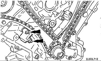
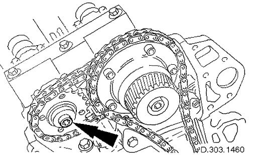
9 18. Loosen the bolt which secures the sprocket to the camshaft. 19. Loosen the bolt which secures the VVT unit to the camshaft. 20. Remove the primary chain tensioner bolts. 9/26


10 21. Remove the tensioner assembly. Remove the tensioner. Remove the tensioner back-plate. 22. Remove the chain tensioner blade. Remove the pivot bolt which secures the tensioner blade. Remove the tensioner blade. 23. Remove the chain from the VVT unit and from the crankshaft pulley. 10/26

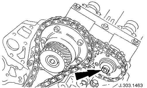
11 24. Remove the camshaft locking tool and transfer it to Bank 2 camshafts, aligning the shafts slightly as necessary Loosen the bolt which secures the sprocket to the camshaft. 11/26

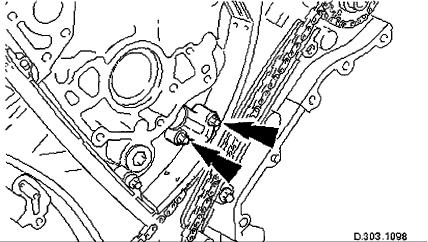
12 26. Loosen the bolt which secures the VVT unit to the camshaft. 27. Remove the primary chain tensioner bolts. 12/26

13 28. Remove the tensioner assembly. Remove the tensioner. Remove the tensioner back-plate. 29. Remove the chain tensioner blade. Remove the pivot bolt which secures the tensioner blade Remove the tensioner blade. 30. Reposition the VVT unit and exhaust camshaft sprocket forward along thecamshaft bosses and remove the chain 13/26
14 from the VVT unit and from the crankshaft sprocket. 31. Note the orientation of the sprockets relative to each other (half a tooth out of line). 32. Clean and inspect all relevant components. Installation 14/26

15 1. Install the chain tensioning tool to the exhaust camshaft sprocket, Bank 2. Reposition the sprocket (and the VVT unit) for the most advantageous position for use of the tool. Remove the tool. 2. Install the primary timing chain, Bank 2. Install the primary chain over the crankshaft sprocket and the VVT unit sprocket. There must be no slack on the drive side of the primary chain and the VVT unit must not be rotated on the camshaft (or the tensioning tool may not fit). Slide the VVT and exhaust sprocket fully rearwards onto the respective camshafts. 15/26
 between the primary chain tensioner and tensioner blade, to take up the slack in the chain. http://alldatapro.")
16 3. Install the primary chain tensioner blade. Position the tensioner blade to the cylinder block. Install the retaining / pivot bolt and tighten it to Nm. 4. Install the primary chain tensioner assembly. Use a wedge (or two if required) between the primary chain tensioner and tensioner blade, to take up the slack in the chain. 16/26
17 5. Tighten the exhaust camshaft sprocket securing bolt. Install the chain tensioner tool to the sprocket holes. Apply force to the tool in an anti-clockwise direction to tension the chain on its drive side. Whilst applying the opposing force to the sprocket and chain, tighten the sprocket securing bolt to Nm. 17/26
, check that the wedges are still in place, tighten the VVT unit securing bolt in two stages.")
18 6. Tighten the VVT unit securing bolt. Whilst still applying the opposing force to the sprocket and chain (using ), check that the wedges are still in place, tighten the VVT unit securing bolt in two stages. First to Nm and then finally to Nm. Remove the chain tensioning tool and the wedges(s). 7. Remove the camshaft locking tool and transfer it to Bank 1 camshafts, aligning the shafts slightly as necessary. 18/26
 for the most advantageous position for use of the tool. Remove the tool. http://alldatapro.")
19 8. Install the chain tensioning tool to the exhaust camshaft sprocket, Bank 1. Reposition the sprocket (and the VVT unit) for the most advantageous position for use of the tool. Remove the tool. 19/26


20 9. Install the primary timing chain, Bank 1. Install the primary chain over the crankshaft sprocket and the VVT unit sprocket. There must be no slack on the drive side of the primary chain and the VVT unit must not be rotated on the camshaft (or the tensioning tool may not fit). 10. Install the primary chain tensioner blade. Position the tensioner blade to the cylinder block. Install the retaining / pivot bolt and tighten it to Nm. 20/26

21 11. Install the primary chain tensioner assembly. Use a wedge (or two if required) between the primary chain tensioner and tensioner blade, to take up the slack in the chain. 12. Tighten the exhaust camshaft sprocket securing bolt. Install the chain tensioner tool to the sprocket holes. Apply force to the tool in an anti-clockwise direction to tension the chain on its drive side. Whilst applying the opposing force to the sprocket and chain, tighten the sprocket securing bolt to Nm. 21/26
, check that the wedges are still in place, tighten the VVT unit securing bolt in two stages.")
22 13. Tighten the VVT unit securing bolt. Whilst still applying the opposing force to the sprocket and chain (using ), check that the wedges are still in place, tighten the VVT unit securing bolt in two stages. First to Nm and then finally to Nm. Remove the chain tensioning tool and the wedge(s). 14. Remove the camshaft locking tool Raise the vehicle on the ramp. 16. Remove the crankshaft setting tool /26
23 17. Install the crankshaft position sensor. Install the sensor to the flywheel housing and install the securing bolt. Tighten to 6-8 Nm. Install the access grommet to the housing. 18. Lower the ramp. 19. Install new seals to the VVT bush carrier, Bank 1. Install the new sealing rings to the carrier bush Groove. 23/26

24 20. Install the VVT bush carrier to the cylinder block. Lubricate the seals and the bush. Install the bush carrier assembly. Check that the ring dowels are engaged squarely. Fully locate the assembly as much as possible by hand pressure. Install the three securing bolts. Tighten to Nm. 24/26

25 21. Install new seals to the VVT bush carrier, Bank 2. Install the new sealing rings to the carrier bush groove. 22. Install the VVT bush carrier to the cylinder block. Lubricate the seals and the bush. Install the bush carrier assembly. Check that the ring dowels are engaged squarely. Fully locate the assembly as much as possible by hand pressure. Install the two securing bolts and one nut. Tighten to Nm. 25/26
26 23. Install the VVT solenoid to each bush carrier, if removed earlier. Check the seal areas and locate the solenoid to the bush carrier. Install the securing bolt. Tighten to 8-10 Nm. 24. Install the Timing Cover. 25. Move the engine compartment cover from the service position and connect the gas struts. 26. Remove the paint protection sheets and close the cover. 27. Connect the battery and install the battery cover. 26/26
vw-wi://rl/a.en-gb.a00.5a60.27.wi:: xml?xsl=3
 Page 1 of 7 Removing and installing balance shaft assembly Special tools and workshop equipment required Locking pin -T10115- Locking tool -T10255- Removing Remove sump Chapter. Rotate crankshaft to TDC
DRIVE COMPONENTS REMOVAL. 9. FXCW/C: see Figure Remove bolt (9), sprocket retainer (8), and thrust washer (7). NOTE PRIMARY DRIVE LOCKING TOOL
, sprocket retainer (8), and thrust washer (7). NOTE PRIMARY DRIVE LOCKING TOOL") DRIVE COMPONENTS REMOVAL PART NUMBER HD-7977 TOOL NAME PRIMARY DRIVE LOCKING TOOL S To remove the primary chain, remove compensating sprocket, clutch assembly and primary chain as an assembly:. Remove
DRIVE COMPONENTS REMOVAL PART NUMBER HD-7977 TOOL NAME PRIMARY DRIVE LOCKING TOOL S To remove the primary chain, remove compensating sprocket, clutch assembly and primary chain as an assembly:. Remove
Installation Instructions
 The IMS ETERNAL FIX PATENT PENDING Installation Instructions EPS recommends professional installation for the Eternal IMS Fix. Please take all precautionary safety measures. We also recommend putting the
3.2.3 Rear Door Window and Quarter Window Carrier Assembly
 Tighten all bolts. Tighten bolts marked -1- and -2- in specified sequence. Tightening torque: 8 Nm Remaining bolts can be tightened in any sequence. Insert door window -3- through window recess without
1 of 2 3/3/2017 4:49 PM
 1 of 2 3/3/2017 4:49 PM Front Door Window, Assembly Overview 1 - Window guide - Inserted on flange 2 - Door 3 - Inner window recess seal - Inserted on flange 4 - Bolt - 20 Nm 5 - Carrier assembly - Window
RTI TECHNOLOGIES, INC.
 RTI TECHNOLOGIES, INC. BRC500 & BRC550 Arbor/Spindle Mechanism Adjustment & Service Technical Instructions The arbor/spindle mechanism of the BRC500/550 is designed to be robust for long life. Occasionally
Typical Group D Rear Acoustical Cover Installation
 SERIES 60 SERVICE MANUAL 1. Gear Case Cover 5. Bolt 2. Gear Case 6. Acoustical Cover 3. Acoustical Cover Snap 7. Acoustical Cover 4. Acoustical Cover Clip 8. Nut Figure 1-179 Typical Group D Rear Acoustical
To install new top weight plate bushings in G7 strength units.
 1/5 PURPOSE To install new top weight plate bushings in G7 strength units. RE-WORK PARTS REQUIRED - ZMS4000424 Top Weight Plate Bushing (Quantity 4 per machine). - Matrix Top Weight Plate Bushing Removal
Enginetech Inc Tech Assistance ext. 340 or 237. January 2000 TB 1758
 Enginetech Inc Tech Assistance 800-410-3664 ext. 340 or 237 Mfg: Removal & Replacement Of Rocker Arms & Shaft Assembly On 1993-99 Chrysler 3.2 & 3.5L VIN J, F & G Engines The AERA Technical Committee offers
Basic steps to time the Gammill quilting machine s rotary sewing hook
 Basic steps to time the Gammill quilting machine s rotary sewing hook 1.) Turn the machine off and unplug it. 2.) With the needle bar in the raised position, remove the bobbin and bobbin case. 3.) Remove
Before use please read & understand this manual, paying particular attention to the safety instructions.
 OPERATOR S MANUAL AND PARTS LIST 12 HAND PUSH ROLLER MOWER - THHMR Sales & Helpline 01793 333220 www.thehandy.co.uk Before use please read & understand this manual, paying particular attention to the safety
Anti-Chattering Retrofit Assembly
 Anti-Chattering Retrofit Assembly Please follow through these instructions carefully and thoroughly. If you have questions, feel free to contact a Bend-Tech service representative at our office 651-257-8715
LS7 CHEVROLET TOP MOUNT Installation Manual For Systems with A/C #13460 / #13490
 LS7 CHEVROLET TOP MOUNT Installation Manual For Systems with /C #13460 / #13490 PLESE RED LL INSTRUCTIONS EFORE INSTLLING NY COMPONENTS OF THE TRU TRC SERPENTINE SYSTEM Important: Thoroughly read the instructions,
Removing Right-Side. Components. Right-Side. Components. Click Here to Go Back AT THIS POINT
 Click Here to Go Back NOTE: There is an oil passage beneath the driven gear/drive gear assembly. This passage should be plugged prior to removing the driven gear and drive gear. Failure to do so could
Maintenance Information
 16601023 Edition 2 January 2014 Air Impact Wrench 2705P1 Maintenance Information Save These Instructions Product Safety Information WARNING Failure to observe the following warnings, and to avoid these
CIRRUS AIRPLANE MAINTENANCE MANUAL
 PROPELLER ASSEMBLY 1. DESCRIPTION The propeller assembly consists of a hollow aluminum hub which supports the propeller blades and also houses the pitch changing mechanism. Movement of propeller blades
(6) Plastic Retainers. Passenger/Right. Passenger/Right Support Brackets
 Plastic Retainers. Passenger/Right. Passenger/Right Support Brackets") PART#R102580 PARTS LIST: 1 Driver/Left HD Running Board 4 8mm Bolt/Nut Plates 1 Passenger/Right HD Running Board 4 8mm Plastic Retainers 2 Driver/Left & Center Mount Bracket 14 8mm-1.25 x 30mm Hex Bolts
PART#R102580 PARTS LIST: 1 Driver/Left HD Running Board 4 8mm Bolt/Nut Plates 1 Passenger/Right HD Running Board 4 8mm Plastic Retainers 2 Driver/Left & Center Mount Bracket 14 8mm-1.25 x 30mm Hex Bolts
N. 15th Street, Middlesboro, KY FLIP TARP DUMP BODY INSTALLATION INSTRUCTIONS
 1-800-248-7717 1002 N. 15th Street, Middlesboro, KY 40965 FLIP TARP DUMP BODY INSTALLATION INSTRUCTIONS Congratulations on your purchase of a Mountain Flip Tarp Dump Body tarping system. With tarping systems
Door window. Front door window, assembly overview
 64-50 Door window Front door window, assembly overview 1 - Window channel Pushed onto flange 2 - Door window Removing Page 64-52 Adjusting Page 64-53 3 - Door 4 - Outer window channel Pushed onto flange
Customer Notice: Congratulations again on your SawStop purchase, and thank you! -SawStop Tualatin, OR
 Customer Notice: Congratulations on the purchase of this Sliding Crosscut Attachment. As the owner of a SawStop saw, you are familiar with our high standards for quality, fit and finish. Different from
NUMBER: S.M. REF.: Listed in Table ENGINE: Series 50/50G DATE: October 2013 SUBJECT: MACHINING CYLINDER BLOCK COUNTERBORES
 NUMBER: 10 25 13 S.M. REF.: Listed in Table ENGINE: Series 50/50G DATE: October 2013 SUBJECT: MACHINING CYLINDER BLOCK COUNTERBORES ADDITIONS, REVISIONS, OR UPDATES Publication Number Platform Section
Additional Information
 NUMBER: 1 34 13 S.M. REF.: Listed in Table ENGINE: EPA04/07 Series 60 DATE: January 2013 SUBJECT: CHECKING CYLINDER LINER PROTRUSION ADDITIONS, REVISIONS, OR UPDATES Publication Number Platform Section
Replacement of Pitch Link Retainer and Service Improvement of the Pitch Control System. Effectivity: Helicopters manufactured prior to January, 1981
 Page 1 of 12 Date: December 2, 1981 Subject: Models: Replacement of Pitch Link Retainer and Service Improvement of the Pitch Control System F-28C and 280C Effectivity: Helicopters manufactured prior to
Installation instructions for FC14S Forward Controls for Shadow ACE and Aero 1100
 Installation instructions for FC14S Forward Controls for Shadow ACE and Aero 1100 It is highly recommended that you use a thread lock compound such as Loctite brand on all threads to keep them from vibrating
ELECTRIC TOOL CORPORATION
 Cat. No. -0 / Hex Demolition Hammer Cat. No. 0-0 Spline Rotary Hammer MILWAUKEE ELECTRIC TOOL CORPORATION W. LISBON ROAD BROOKFIELD, WISCONSIN 00-0 -9-00 d 000 -9-00 d SpecialTools Require Forcing discs
SECTION 9: PARTS. Table Breakdown REF PART # DESCRIPTION REF PART # DESCRIPTION
 SECTION 9: PARTS Table Breakdown 1 2 3 4 5 6 7 8 9 10 11 12 13 14 15 16 17 18 19 20 21 22 23 24 23 25 17 26 27 8 1 P0675001 CAP SCREW M8-1.25 X 30 15 P0675015 SUPPORT BLOCK 2 P0675002 TABLE SUPPORT BLOCK
Installation instructions for FC9 & FC18 Forward Controls for Yamaha V-Max
 Installation instructions for FC9 & FC18 Forward Controls for 1985-2007 Yamaha V-Max It is highly recommended that you use a thread lock compound such as Loctite brand on all threads to keep them from
APS Small Seeds Box Assembly Instructions
 APS Small Seeds Box Assembly Instructions For APS15 Series All Purpose Seeder Manual No. 313-473M Before You Start! When you see this symbol, the subsequent instructions and warnings are serious - follow
Inspection. Assembly Install the springs. 1. Discard the 0-rings. 2. Clean all parts in cleaning solvent.
 6010-34 Inspection 3. Install the springs. 1. Discard the 0-rings. 2. Clean all parts in cleaning solvent. 3. If spring test equipment is available, check the tension of each spring according to the specifications
REPAIR INSTRUCTIONS. Cat. No Cat. No MILWAUKEE ELECTRIC TOOL CORPORATION. SDS Max Demolition Hammer. SDS Max Rotary Hammer
 Cat. No. 9-0 SDS Max Demolition Hammer Cat. No. -0 SDS Max Rotary Hammer MILWAUKEE ELECTRIC TOOL CORPORATION W. LISBON ROAD BROOKFIELD, WISCONSIN 00-0 8-9-0 d 000 8-9-0 d Special Tools Require Forcing
Orbital Test Stand. Operations and Assembly Manual. Department of Mechanical Engineering Northern Arizona University Flagstaff, AZ 86011
 Orbital Test Stand Operations and Assembly Manual Department of Mechanical Engineering Northern Arizona University Flagstaff, AZ 86011 TABLE OF CONTENTS 1.0 Components List... 2 2.0 Assembly Instructions...
To remove sanding pad, turn counterclockwise.
 Disassembly Instructions - Dynorbital EXTREME Models: All Important: Disconnect sander from the air supply. Notice: Use these instructions along with the tool manual. To avoid damage, use the special repair
It s a good idea to identify the Front and Rear cylinder heads. before starting the teardown process.
 It s a good idea to identify the Front and Rear cylinder heads using a paint pen before starting the teardown process. Use a 17/64 drill bit (or 6mm if you have metric drills or round stock) to lock the
Replacing the build plate clamps
 Repair manual Replacing the build plate clamps Instructions The build plate clamps hold the glass plate in place on the heated bed. There are two fixed in place at the back of the heated bed and two at
RULTRACT RETRACTOR CABLE REPLACEMENT INSTRUCTIONS. Rultract, Inc. is the ONLY authorized service center in the U.S.A.
 RULTRACT RETRACTOR CABLE REPLACEMENT INSTRUCTIONS Rultract, Inc. is the ONLY authorized service center in the U.S.A. When your Rultract instrument needs repair or service, contact Rultract Inc. or Rultract
2. Install two guide studs, J 36107, to the gear case. See Figure
 SERIES 60 SERVICE MANUAL 2. Install two guide studs, J 36107, to the gear case. See Figure 1-174. 1. Front Gear Case Cover 4. Locating Dowel (Round) 2. Front Engine Lift Bracket 5. Locating Dowel (Diamond)
TorqueMaster Replacement Spring
 TorqueMaster Replacement Spring Installation Instructions NOTE: Use these installation instructions in conjunction with the TorqueMaster Repair / Replacement Spring Program literature. Copyright 999 Wayne-Dalton
3-506 NOTE: CC054D
 Click Here to Go Back Fig. 3-506 NOTE: Position the shift lever part way onto the splines and verify the subtransmission is in Hi range. If not, shift into Hi range. Fig. 3-509 CC054D 25. Place the speedometer
Electric Skein Winder
 Electric Skein Winder Assembly and Use Package Contents 1 - Triangular Body (w/ motor) 1 - Cross Arm 1 - Left Foot (w/ yarn guide) 1 - Right Foot 1 - Adjustable Finger (w/ yarn clip) 3 - Adjustable Fingers
Section A December 2009
 Section A ELEVATOR December 2009 1A Index 1. 47-011053-004 Deflection Chain Gear w/bearing Complete 2. 11-051772-001 Lockwasher (12 mm) 3. 47-011130-004 Bearing Bolt 4. 47-011245-003 Lower Chain Guide
Parts Sheet. RSX096 High Force, Rod Style Actuator EXPLODED VIEW - RSX _00_RSX09. * Specify stroke length when ordering A/R = As Required
 RSX0 High Force, Rod Style Actuator Parts Sheet 00_00_RSX0 EXPLODED VIEW RSX0 0 0 0 PART NO or ITEM Config. Code DESCRIPTION QTY. 0 Leadscrew/Rollerscrew (Standard) Leadscrew/Rollerscrew (TRR Option) 0
Hardware and Components:
 Hardware and Components: (A) 4X 5/16 x 1 Carriage Bolt (B) 2X 5/16 x 2-1/4 Carriage Bolt (C) 2X 5/16 x 3-1/4 Hex Bolt (D) 2X 5/16 x 3/4 Hex Bolt (E) 2X 5/16 x 1-1/4 Hex Bolt (F) 5/16 x 2-1/4 Hex Bolt (G)
RPS. XR Front Drive Updates CORPORATION
 FACTORY CAT 1. To start a replacement of the XR Front Wheel Drive, make sure the machine is on level ground with the rear wheels chocked and always disconnect the batteries. 2. Locate the Positive and
ABM International, Inc. Navigator Assembly Manual
 ABM International, Inc. 1 1.0: Parts List Tablet (Qty. 1) Tablet mount (Qty. 1) NOTE: Mount may appear and operate different then image below Control Box (Qty. 1) Motor Power Supply (Qty. 1) 2 X-axis motor
Installation Instructions
 Installation Instructions For 4 foot / 1.2m Diameter Ultra-high Performance Antenna Model ADxxG-4-T2 Before Installation, please read the instructions carefully. This instruction guide covers the installation
C a r r i a g e A s s e m b l y R e p l a c e m e n t
 E1 TF-CR C a r r i a g e A s s e m b l y R e p l a c e m e n t October 2007 Software Version 5.0 and higher IMPORTANT! TigerStop must be enabled with a code that must be obtained from TigerStop Customer
Tuf-Lite and Tuf-Lite II Fans 4000 Series Hub
 Tuf-Lite and Tuf-Lite II Fans 4000 Series Hub INSTALLATION MANUAL Hudson Tuf-Lite and Tuf-Lite II fan blades Adjustable Pitch Fan Assembly 15 thru 20 Diameter Hudson Tuf-Lite (black) fan blades are made
ABM International, Inc.
 ABM International, Inc. Lightning Stitch required 1 1.0: Parts List head and motor assembly (Qty. 1) Reel stand (Qty. 1) Needle bar frame clamp (Qty. 1) Motor drive (Qty. 1) 2 Cable harness with bracket
Assembly Instructions
 P/N 8650/8655 Assembly Instructions NOTE: Your Sherline CNC Cam Grinder is double boxed and secured to a wooden shipping frame. Upon delivery, check the outer box for damage. If the box is damaged, take
Small Block Ford. 289 / 302 / 351W / 5.0 Installation Manual For Systems with A/C #13600 / #13620
 Small Block Ford 289 / 302 / 351W / 5.0 Installation Manual For Systems with A/C #13600 / #13620 Billet Specialties, Inc. 500 Shawmut Avenue. La Grange, Illinois 60526 Tech Line (708) 588-0505 Fax (708)
w w w. h d o n l i n e s h o p. d e TIMKEN BEARING CONVERSION TOOL GENERAL INSTALLATION -J04672 REV Kit Number Models
 -J067 REV. 008-07- GENERAL Kit Number 8-08 Models TIMKEN BEARING CONVERSION TOOL For model fitment information, see the P&A Retail Catalog or the Parts and Accessories section of www.harley-davidson.com
Big Block Installation Manual For Systems without A/C
 Big Block Installation Manual For Systems without A/C Billet Specialties, Inc. 500 Shawmut Ave. La Grange, IL 60526 Tech Line (708) 588-0505 Fax (708) 588-7181 Hardware List For Chevrolet Big Block Tru
Hardware and Components:
 Hardware and Components: (A) 5/16 x 2 Hex Bolt (B) 5/16 x 2-1/4 Hex Bolt (C) 5/16 x 2-1/2 Hex Bolt (D) 4X 5/16 x 3/4 Hex Bolt (E) 4X 5/16 x 1-1/4 Hex Bolt (F) 11X 5/16 Flat Washer (G) 12X 5/16 Nylock Nut
Sliding Crosscut Table installation guide
 Sliding Crosscut Table installation guide model tsa-sa48 A Note About Color Variations Among Anodized Aluminum Components Congratulations on the purchase of this SawStop Sliding Crosscut Table. We at SawStop
AFB (AIR FAN BEARING) INSTALLATION GUIDE
 INSTALLATION GUIDE") 654 AFB (AIR FAN BEARING) INSTALLATION GUIDE AFB PARTS Bearing Housing - Secured together with two 3/8 x 1.25 in. Cap Screws Black Wiper Seals - Secured together with O-ring cord (Subsequently depicted
654 AFB (AIR FAN BEARING) INSTALLATION GUIDE AFB PARTS Bearing Housing - Secured together with two 3/8 x 1.25 in. Cap Screws Black Wiper Seals - Secured together with O-ring cord (Subsequently depicted
Tuf-Lite and Tuf-Lite II Fans 4000 Series Hub
 Tuf-Lite and Tuf-Lite II Fans 4000 Series Hub INSTALLATION MANUAL Hudson Tuf-Lite and Tuf-Lite II fan blades Adjustable Pitch Fan Assembly 15 thru 20 Diameter Hudson Tuf-Lite (black) fan blades are made
Multi-Wing Z Series Fans Blade Pitch Angle Setting Instructions
 Multi-Wing Z Series Fans Blade Pitch Angle Setting Instructions Before You Begin: To maintain balance of fan: Mark the hub castings across a joint, so the fan hub can be reassembled in the same orientation.
Tuf-Lite III Fans 3000K Series Hub
 Tuf-Lite III Fans 3000K Series Hub INSTALLATION MANUAL Adjustable Pitch Fan Assembly 11 thru 15 Diameter Hudson Tuf-Lite III fan blades Hudson Tuf-Lite III fan blades are of single piece fiberglass reinforced
model tsa-sa48 Sliding Crosscut Table installation guide
 model tsa-sa48 Sliding Crosscut Table installation guide A Note About Color Variations Among Anodized Aluminum Components Congratulations on the purchase of this SawStop Sliding Crosscut Table. We at SawStop
Front axle components, overview
 j a t Front axle components, overview 40-1 General Information Load bearing components and parts of the suspension must not be welded or straightened. Vehicles without drive axle must not be moved, or
SUPER PRO GUN & SUPER PRO GUN II
 MAGNUM VENUS PRODUCTS Maintenance & Repair Manual Part No. M6707-1-1 Revision 04.14.01 Maintenance & Repair Corporate HQ & Mfg. Phone: (727) 573-2955 Fax: (727) 571-3636 Email: info@magind.com Web: www.magind.com
MUELLER. Improved, Centurion Series, Modern Improved, and 107. Fire Hydrants. Inserting Extention Sections. Reliable Connections
 insertion Instructions manual MUELLER Improved, Centurion Series, Modern Improved, and 107 table of contents PAGE Centurion Series Fire Hydrant Adding an Extention 2-3 Improved Fire Hydrant Inserting Extention
PET*STAR 4 OPERATOR MANUAL
 Operator Manual 17315060 Rev. 0 (PS - 4) PET*STAR 4 OPERATOR MANUAL Paragraph Page 1.0 INTRODUCTION... 2 2.0 INSTALLATION... 2 3.0 ALIGNMENT... 2 4.0 SPHERICAL ROLLER BEARING & PILLOW BLOCK... 5 5.0 OUTBOARD
Drake Off Road Hood Hold Downs Installation Guide
 Installation Time: 30 Minutes Tools Required: Drake Off Road Hood Hold Downs Installation Guide 3/8 drive ratchet 13mm socket 10mm socket (deep-well socket helpful) 13mm wrench (2x) 4mm allen wrench 5mm
JARVIS. Model Brisket Scissor EQUIPMENT... TABLE OF
 Model 423-17 Brisket Scissor EQUIPMENT SELECTION... Ordering No. TABLE OF CONTENTS... Page Model 423--17... 4037003 Air Filter / Regulator / Lubricator 3022003 Air Hose Assembly... 3059018 Balancer...
Tuf-Lite II Fans 3000H Series Hub
 Tuf-Lite II Fans 3000H Series Hub INSTALLATION MANUAL Adjustable Pitch Fan Assembly 5 through 14 Diameter Hudson Tuf-Lite II Fan Blades Hudson Tuf-Lite II (white, prev. Blue**) are made from fiberglass
Tuf-Lite II Fans 3000H Series Hub
 Tuf-Lite II Fans 3000H Series Hub INSTALLATION MANUAL Adjustable Pitch Fan Assembly 5 through 14 Diameter Hudson Tuf-Lite II Fan Blades Hudson Tuf-Lite II (white, prev. blue**) fan blades are made from
Tuf-Lite II Fans 3000HC Series Hub
 Tuf-Lite II Fans 3000HC Series Hub INSTALLATION MANUAL Hudson Tuf-Lite II fan blades Adjustable Pitch Fan Assembly 8 through 10 Diameter Hudson Tuf-Lite II (White) are made from fiberglass reinforced vinyl-ester
1. Turn off or disconnect power to unit (machine). 2. Push IN the release bar on the quick change base plate. Locking latch will pivot downward.
. 2. Push IN the release bar on the quick change base plate. Locking latch will pivot downward.") Figure 1 Miniature Quick Change Applicators, of the end feed type, are designed to crimp end feed strip terminals to prestripped wires. Each applicator is set up to accept the strip form of certain specific
Figure 1 Miniature Quick Change Applicators, of the end feed type, are designed to crimp end feed strip terminals to prestripped wires. Each applicator is set up to accept the strip form of certain specific
INSTALLATION INSTRUCTIONS 6 OVAL BENT END SIDEBARS DODGE RAM 1500, CREW CAB PART#: /241533B
 PARTS LIST: 1 Driver/Left Sidebar 24 8mm x 24mm x 2mm Flat Washers 1 Passenger/Right Sidebar 12 8mm Lock Washers 3 Driver/left, Passenger Center and Rear 6 8mm Hex Nuts 3 INSTALLATION INSTRUCTIONS 6 OVAL
FLIP TARP SINGLE & DOUBLE UNDERBODY TRAILERS
 1-800-248-7717 1002 N. 15th Street, Middlesboro, KY 40965 FLIP TARP SINGLE & DOUBLE UNDERBODY TRAILERS INSTALLATION INSTRUCTIONS Congratulations on your purchase of a Mountain Flip Tarp Trailer system.
INSTALLATION INSTRUCTIONS 3"/4 BENT END SIDEBARS FORD F-150 SUPERCREW PART # DZ /DZ
 INSTALLATION INSTRUCTIONS 09-12 FORD F-150 SUPERCREW PART # DZ 372697/DZ 372699 PARTS LIST: 1 Driver/Left Sidebar 4 1/2 Lock Washers 1 Sidebar 4 12mm x 32mm OD x 3mm Flat Washers 1 Driver/Left Mounting
Eraser Conveyor Belt Cleaning System IWARNING Always obey all applicable safety rules. Be sure all power to the conveyor has been disconnected and con
 INSTALLATION GUIDE LIB-CP-REA-03-01 Rev. 10 Eraser Conveyor Belt Cleaning System ARGONICS Eraser Conveyor Belt Cleaning System IWARNING Always obey all applicable safety rules. Be sure all power to the
Click Here to Go Back
 Click Here to Go Back Fig. -94 Fig. -97 CC42D 10. Remove the cap screw securing the gear shift stopper plate pin retainer; then remove the retainer. Fig. -95 CC45D 12. Remove the link arm and account for
It is highly recommended that you use a thread lock compound such as Loctite brand on all threads to keep them from vibrating loose.
 Installation instructions for FC12 Forward Controls for Kawasaki Vulcan 750 It is highly recommended that you use a thread lock compound such as Loctite brand on all threads to keep them from vibrating
What is a fastener? A device to locate or hold parts
 What is a fastener? A device to locate or hold parts As a repair technician you will become skilled at removing, reconditioning, replacing, and installing fasteners. An important skill to learn is how
Instruction Sheet RADIO FREQUENCY SYSTEMS. Install. Instr. for Microwave Parabolic Antennas 2.4 m (8 ft) No Rev.
 No Rev.") Instruction Sheet No. 412764 Rev. B ECO 12469 Install. Instr. for Microwave Parabolic Antennas 2.4 m (8 ft) These Installation Instructions are valid for antennas in the following version: reflector 2.4
Instruction Sheet No. 412764 Rev. B ECO 12469 Install. Instr. for Microwave Parabolic Antennas 2.4 m (8 ft) These Installation Instructions are valid for antennas in the following version: reflector 2.4
LU6X-130 Instructions and Parts List (including LU6X Basic) Operating Instructions
 Operating Instructions") LORTONE LU6X-130 Item # 061-092 LU6X Basic Item # 061-090 LU6X-130 Instructions and Parts List (including LU6X Basic) Operating Instructions Introduction The LU6X is one the most versatile pieces of equipment
LORTONE LU6X-130 Item # 061-092 LU6X Basic Item # 061-090 LU6X-130 Instructions and Parts List (including LU6X Basic) Operating Instructions Introduction The LU6X is one the most versatile pieces of equipment
INSTALLATION INSTRUCTIONS
 INSTALLATION INSTRUCTIONS PROTRAXX OVAL STEP BAR APPLICATION: 2009-2017 Dodge Ram 1500 Crew/Quad Cab 2010-2017 Dodge Ram 2500/500 Crew Cab PART NUMBER: 21-550, 21-555, 21-50, 21-55 AUTOMOTIVE PRODUCTS,
INSTALLATION INSTRUCTIONS
 INSTALLATION INSTRUCTIONS PARTS REQUIRED Single QuickStand Lite Parts A (1) Lower Arm A B C D B (1) Upper Arm C (1) Base D (1) Base Plate E (1) M8 Dynamic Arm Long F (1) Clamp Bracket G H (1) VESA Plate
Small Block Ford. 289 / 302 / 351W / 5.0 Installation Manual For Systems without A/C #13605 / #13625
 Small lock Ford 289 / 302 / 351W / 5.0 Installation Manual For Systems without /C #13605 / #13625 illet Specialties, Inc. 500 Shawmut venue. La Grange, Illinois 60526 Tech Line (708) 588-0505 Fax (708)
BHJ Products, Inc. Parts List & Instructions
 Product Name: O-Ring Groove Cutter Adjustable Tool Block Upgrade Page 1 of 5 Prototype Kit Contents: 1x Adjustable Tool Block 1x Adjustable Tool Holder 1x Graduated Adjusting Screw 1x 1/8 Registration
LANVRT10. Instructions. Lankota Vertical Unload Auger Removal Tool for JD 00 to S series combines. 270 West Park Avenue Huron, SD
 LANVRT10 Instructions Lankota Vertical Unload Auger Removal Tool for JD 00 to S series combines 270 West Park Avenue Huron, SD 57350 866-526-5682 Page 1 Numerical Parts List Part Numbers Description Quantity
C-15 Truck Engine 9NZ00001-UP(SEBP ) - Document Structure. Media Number -RENR Publication Date -01/07/2008 Date Updated -22/07/2008
 - Document Structure. Media Number -RENR Publication Date -01/07/2008 Date Updated -22/07/2008") Page 1 of 8 Shutdown SIS Previous Screen Product: TRUCK ENGINE Model: C-15 TRUCK ENGINE 9NZ Configuration: C-15 Truck Engine 9NZ00001-UP Disassembly and Assembly C-15, C-16 and C-18 Truck Engines Media
Page 1 of 8 Shutdown SIS Previous Screen Product: TRUCK ENGINE Model: C-15 TRUCK ENGINE 9NZ Configuration: C-15 Truck Engine 9NZ00001-UP Disassembly and Assembly C-15, C-16 and C-18 Truck Engines Media
caroma marc newson shower mixer
 caroma marc newson shower mixer PLUMBERS INSTALLATION INSTRUCTIONS IS1215A(07/12) Important Information Brazed connections should NOT be made directly onto the mixer, as excessive heat will cause permanent
SERVICE PARTS LIST. M18 FUEL SAWZALL Reciprocating Saw F56A BULLETIN NO CATALOG NO
 47(5x) 46 45 00 44 0 59 43 42 84 51 57 46 47 48 59 83 64 77 48 47(2x) 49(2x) 40 58 See service note on page 5 41 82 51 40 41 42 43 44 45 87 52 27 28 34 57 29 (6x) 60 28 EXAMPLE: Component Parts (Small
IMPORTANT WARRANTY & INSTALLATION INSTRUCTIONS ATTACHED
 IMPORTANT WARRANTY & INSTALLATION INSTRUCTIONS ATTACHED For Full-Color Installation Instructions, Please Visit: VOLANT.COM and Search by Part Number Please be sure to review the enclosed instructions prior
DO35 MAINTENANCE INSTRUCTIONS
 CUSTOMER INFORMATION SHEET NO. 038 DO35 MAINTENANCE INSTRUCTIONS (DO35 V3 LAUNCHED PRODUCTION JUNE 2017) Table of Contents 1.0 Replacing Spindle Bushes V3... 22 2.0 Replacing Locking Mechanism V3... 6
Tuf-Lite III Fans K Hi Temp 3000KHT Series Hub
 Tuf-Lite III Fans K Hi Temp 3000KHT Series Hub INSTALLATION MANUAL Adjustable Pitch Fan Assembly 11 thru 15 Diameter Hudson Tuf-Lite III fan blades Hudson Tuf-Lite III Hi Temp (Red) fan blades are of single
JARVIS. Model25CL-4,5,6 Hock Cutter and Loin Dropper. 25CL--5 Front Legs and Horns. 25CL--4 Hind Legs and Horns. 25CL--6 Loins
 Model25CL-4,5,6 Hock Cutter and Loin Dropper 25CL--4 Hind Legs and Horns 25CL--5 Front Legs and Horns 25CL--6 Loins EQUIPMENT SELECTION... Ordering No. TABLE OF CONTENTS... Page 25CL--4... 4025007 25CL--5...
001-Component-build. Build the following Contraptor components before assembly:
 001-Component-build Build the following Contraptor components before assembly: http://www.contraptor.org/make-linear-rail-v2#assembly http://www.contraptor.org/make-linear-bearings-v2#assembly http://www.contraptor.org/make-sliding-elements#assembly
Tuf-Lite II Fans H Hi Temp 3000HT Series Hub
 Tuf-Lite II Fans H Hi Temp 3000HT Series Hub INSTALLATION MANUAL Hudson Tuf-Lite II Hi Temp Fan Blades Adjustable Pitch Fan Assembly 5 through 14 Diameter Hudson Tuf-Lite II Hi Temp fan blades (Red) are
Form No Assembly & Operating Instructions for: SAFETY PRECAUTIONS
 Form No. 0230 Assembly & Operating Instructions for: 833 20300 83 2220 837 0-0008 078 SHOP PRESS Max. Capacity: 2 Ton These instructions are intended for various shop presses. Some models are shipped assembled
2012+ F30 320i, 328i F22 228i Carbon Fiber S-FLO Intake INSTALLATION GUIDE FOR RACING USE ONLY
 PERFORMNCE ENGINEERING FOR EUROPEN UTOS INSTLLTION GUIDE 2012+ F30 320i, 328i 2014+ F22 228i Carbon Fiber S-FLO Intake FOR RCING USE ONLY Congratulations on your purchase of the WE Tuning Carbon Fiber
Power Train Lift Max. Capacity: 1,250 lbs.
 655 EISENHOWER DRIVE OWATONNA, MN 55060 USA PHONE: (507) 455-7000 TECH. SERV.: (800) 533-6127 FAX: (800) 955-8329 ORDER ENTRY: (800) 533-6127 FAX: (800) 283-8665 INTERNATIONAL SALES: (507) 455-7223 FAX:
4.2 - PUMP MAINTENANCE MODELS: AC, AS, WC, WS
 4.2 - PUMP MAINTENANCE MODELS: AC, AS, WC, WS 4.2.1 - EXPLODED VIEW DRAWING REF NO. 1 2 4 QTY 3 1 1.5 5 ¾ HP HP HP HP HP DESCRIPTION PART # 1 CASE 1.25 x 1 NPT 018266 1 CASE 1.25 X 1 NPT 018268 1 CASE
Passenger/Right Center and Rear Support Brackets. Driver/Left Center and
 PARTS LIST: 1 Driver/Left HD Running Board 24 8mm x 24mm OD x 2mm Flat Washers 1 Passenger/Right HD Running Board 12 s 3 Driver/Left front, passenger center/rear Support Brackets 6 8mm-1.25 Hex Nuts 3
IMPORTANT WARRANTY & INSTALLATION INSTRUCTIONS ATTACHED
 IMPORTANT WARRANTY & INSTALLATION INSTRUCTIONS ATTACHED Please Forward All Attached Information to Consumer Warranty Not Valid Unless Returned to Volant Performance STOP Please be sure to review the enclosed
SERVICE PARTS LIST PAGE 1 OF 6 BASE ASSEMBLY SPECIFY CATALOG NO. AND SERIAL NO. WHEN ORDERING PARTS 12" DUAL BEVEL COMPOUND MITER SAW B27B
 PAGE 1 OF 6 BASE ASSEMBLY 00 0 EXAMPLE: Component Parts (Small #) Are Included When Ordering The Assembly (Large #). SPECIFY CATALOG NO. AND NO. WHEN ORDERING PARTS = Part number change from previous service
Heacent 3D printer assembly manual. Prusa i3
 Heacent 3D printer assembly manual Prusa i3 Y-axis assembly 1. Y axis motor section: Find the belowing parts bag, Y-axis motor Assembled parts are separated as shown below, note that the motor between