G0614 Control Box Parts
|
|
|
- Norma Stevenson
- 5 years ago
- Views:
Transcription
 546-9663 or techsupport@grizzly.")

1 READ THIS FIRST Model G0613/G0614 ***IMPORTANT UPDATE*** 192 For Machines Mfd. Since 07/06 and Owner's Manual Revised 12/07 For questions or help with this product contact Tech Support at (570) or The following changes were recently made to this machine since the owner's manual was printed: pump rotary switch, wiring diagram, and component diagram. G0613: Changed G0614: Changed parts, wiring diagram, and components diagram Aside from 106this information, all other content in the owner's manual applies and MUST be read and under104safety. IMPORTANT: Keep this update with the owner's manual for future reference. 104 stood for your own For questions or help, contact 109 our Tech Support at (570) or G0613 Parts V2 REF PART # 255V2 P V2 DESCRIPTION PUMP ROTARY SWITCH XB7ND21 V Figure 1. G0613 control panel REF Rotary Switch PART # P DESCRIPTION Figure 2. G0613 pump motor capacitor. RUN CAPACITOR FJ SHGSR-V 3MFD 450V COPYRIGHT MAY, 2017 BY GRIZZLY INDUSTRIAL, INC. WARNING: NO PORTION OF THIS MANUAL MAY BE REPRODUCED IN ANY SHAPE OR FORM WITHOUT THE WRITTEN APPROVAL OF GRIZZLY INDUSTRIAL, INC. #JH18697 PRINTED IN TAIWAN G0613/G0614 Update (Mfd. Since 07/06) -1-
2 G0614 Control Box Parts 247V2 250V3 251V3 252V V2 252V3 253V2 256V2 254V2 255V2 257V2 REF PART # DESCRIPTION REF PART # DESCRIPTION 246V2 P V2 FUSE HOUSING GIKO KA FSB V V2 P V2 ON BUTTON AP-PBF-22-1/0G V V2 P V2 FUSE 7 X 30MM 1A V V2 P V2 SPEED SWITCH AP-ASS-223-2AW V V3 P V3 CONTACTOR CAI D404A V V2 P V2 ROTARY SWITCH AP-ASS-222-1AW V V3 P V3 CONTACTOR CO9D10G7 V V2 P V2 OFF BUTTON AP-PBF-22-1-BR V V3 P V3 CONTACTOR CO9D10G7 V V2 P V2 E-STOP BUTTON AP ALEPBC-22-1BR V V3-1 P V3-1 OL RELAY NTH 4.5-6A V G0614 Headstock & Pump Motor Parts 7V V3 44V2 40V3 81 REF PART # DESCRIPTION REF PART # DESCRIPTION 7V3 P V3 BODY FRAME V V2 P V2 HANDLE PIPE V V3 P V3 KNOB BOLT M X 25 6-LOBE V P CAP SCREW M X 25 40V3 P V3 FIXED BLOCK V P SET SCREW M X 8-2- G0613/G0614 Update (Mfd. Since 07/06)
 Qty A. Splash Tray... 1 B. Vise Clamp Handle... 1 C. Blade Tension Handles... 2 D. Work Stop Arm... 1 E. Work Stop Rod... 1 F. Headstock Handle... 1 G. Hardware.")
 Qty A. Splash Tray... 1 B. Vise Clamp Handle... 1 C. Blade Tension Handles... 2 D. Work Stop Arm... 1 E. Work Stop Rod... 1 F. Front/Rear Panel... 2 G. Left/Right Panel.")
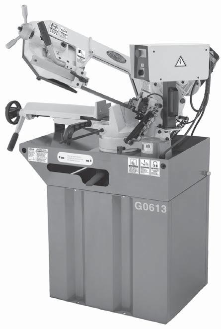
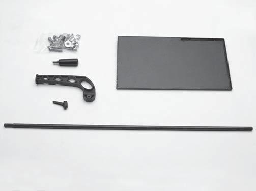
3 G0613 Inventory Inventory The following is a list of items shipped with your machine. Before beginning setup, lay these items out and inventory them. If any non-proprietary parts are missing (e.g. a nut or a washer), we will gladly replace them; or for the sake of expediency, replacements can be obtained at your local hardware store. Shipping Crate: (Figure 1) Qty A. Splash Tray... 1 B. Vise Clamp Handle... 1 C. Blade Tension Handles... 2 D. Work Stop Arm... 1 E. Work Stop Rod... 1 F. Headstock Handle... 1 G. Hardware... 1 Carriage Screws x 5 8"... 8 Hex Nuts Flat Washers 10mm... 4 Hex Bolts M x H. Front/Rear Panels... 2 I. Left/Right Panels... 2 G0614 Inventory Shipping Crate: (Figure 2) Qty A. Splash Tray... 1 B. Vise Clamp Handle... 1 C. Blade Tension Handles... 2 D. Work Stop Arm... 1 E. Work Stop Rod... 1 F. Front/Rear Panel... 2 G. Left/Right Panel... 2 H. Hardware... 1 Carriage Screws x 5 8"... 8 Hex Nuts 5/ Flat Washers 10mm... 4 Hex Bolts M x A B C E F D G A B C H D Figure 2. G0614 inventory. H E F G I NOTICE If you cannot find an item on this list, carefully check around/inside the machine and packaging materials. Often, these items get lost in packaging materials while unpacking or they are pre-installed at the factory. Figure 1. G0613 inventory. G0613/G0614 Update (Mfd. Since 07/06) -3-
4 G0613 Control Box Diagram ON/OFF KJD V 15A ON/OFF Switch Control Panel Terminal Block Start Capacitor 300 MFD 250V Run Capacitor 30 MFD 250V To Power Cord To Limit Switch To Saw Motor To Pump -4- G0613/G0614 Update (Mfd. Since 07/06)


5 G0613 Control Box Figure 3. G0613 control box wiring. Figure 4. G0613 control panel. G0613/G0614 Update (Mfd. Since 07/06) -5-


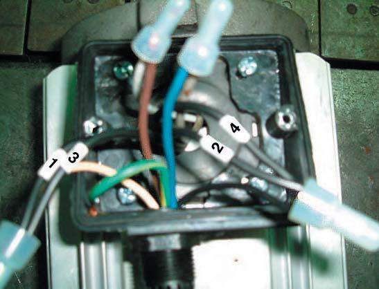
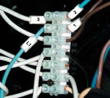
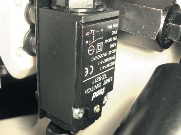
6 G0613 Component Wiring Pump Motor 3MFD 450V Ground Figure 5. Pump motor wiring. Main Motor Ground Figure 6. Main motor wiring. Limit Switch Figure 7. Limit switch wiring. -6- G0613/G0614 Update (Mfd. Since 07/06)
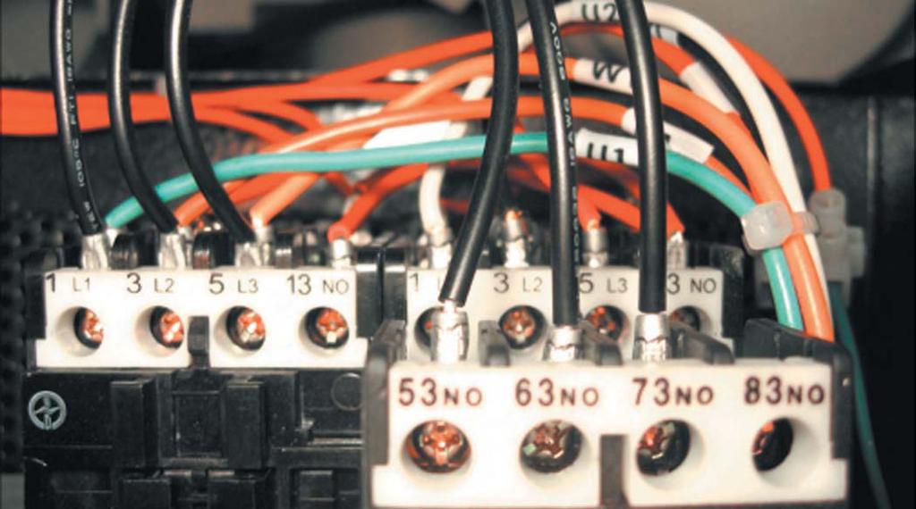
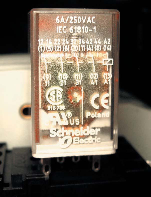
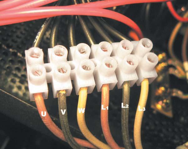
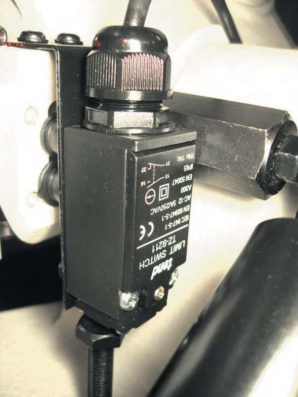
7 OFF Button G0614 Wiring Diagram ON Button Cutting Speed Switch E-Stop Button Pump 1L1 3L2 5L3 13NO 1L1 3L2 5L3 13NO Relay MY-4 220V 2T1 4T2 6T3 14NO 2T1 4T2 6T3 14NO Ground Ground Ground To Pump Motor To Saw Motor To Limit Switch To Power Cord G0613/G0614 Update (Mfd. Since 07/06) -7-


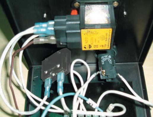
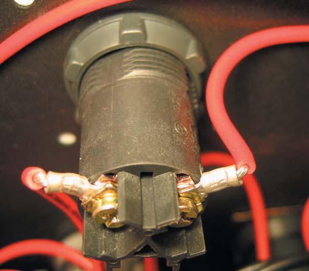
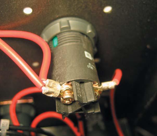
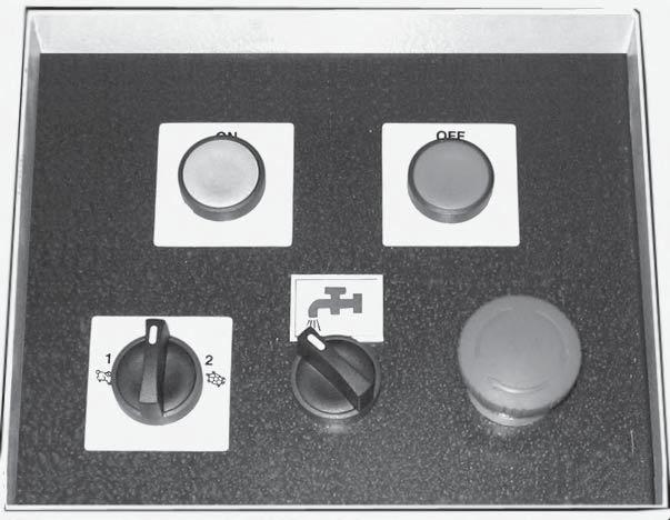
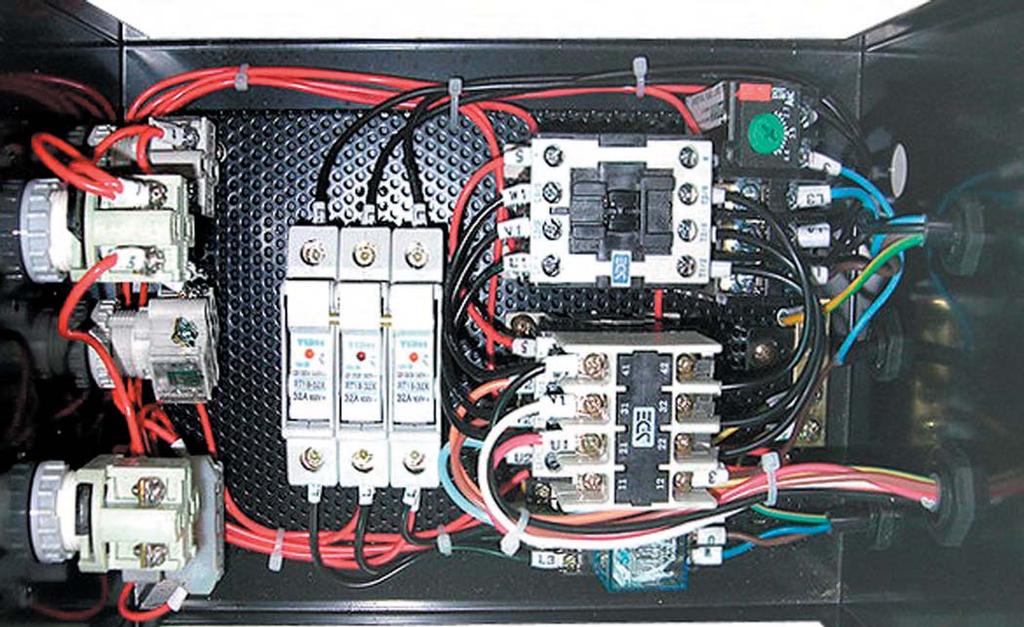
8 G0614 Control Box Figure 8. G0614 control box wiring. Figure 9. G0614 control panel. -8- G0613/G0614 Update (Mfd. Since 07/06)


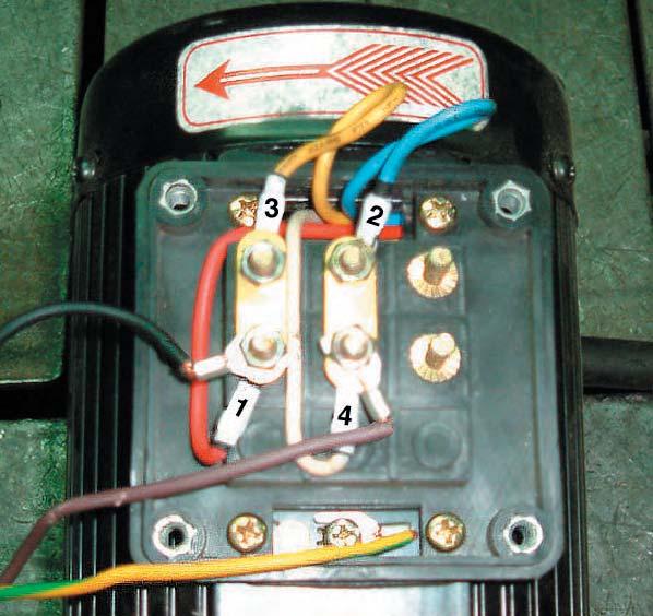
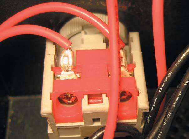
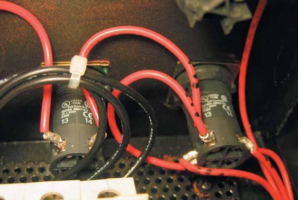
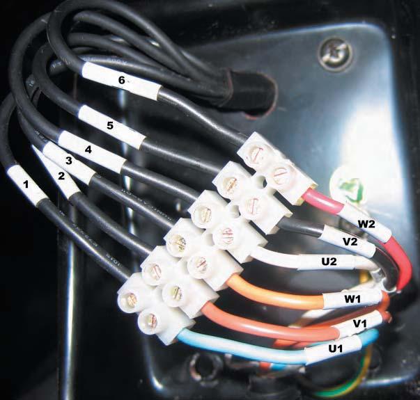
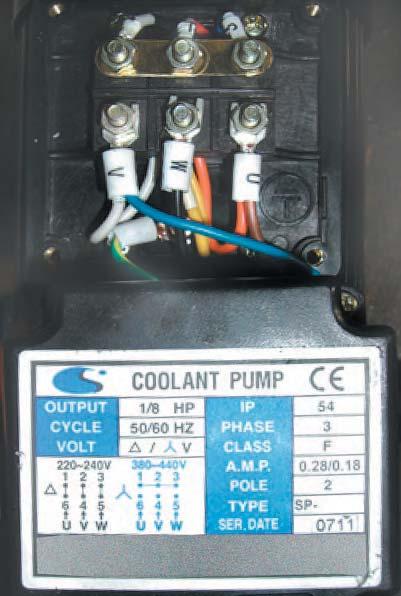
9 G0614 Component Wiring Main Motor GND Figure 10. Motor wiring. Pump Motor GND Figure 11. Pump motor wiring. Limit Switch Figure 12. Limit switch wiring. G0613/G0614 Update (Mfd. Since 07/06) -9-
10
11
12
13
14
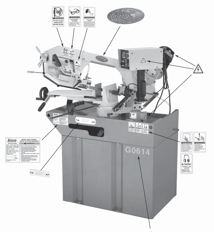
15 Main Specifications: Operation Info Blade Speeds FPM Blade Size " x 82" Head Swivel... 0 to 60 Cutting capacities: 0, round... 7" 0, rectangular...5" x 8 1 4" +45, round " +45, rectangular...4" x 4 1 4" +60, round... 2" +60, rectangular " x 2" Miter cutting capacity... 0 to 60 Other Specifications: Country of Origin...Taiwan Warranty...1 Year Serial Number Location...Grizzly ID Label Features: Swivel Base with Degree Scale Centralized Control Panel Heavy-duty All Steel, One Piece Base Adjustable Hydraulic Down Feed Extra Clamping Capacity Vise with Lever Lock Quick Release Vise Tooth Selection Chart Built-in Cutting fluid System Automatic Shut Off Adjustable Blade Guide System Blade Wheels Have Heavy-duty Ball Bearings -4- G0613/14 Swivel Mast Metal Cutting Bandsaw
16
17 Main Specifications: Operation Info Blade Speeds...170, 341 FPM Blade Size...1" x " Head Swivel... 0 to 60 Cutting capacities: 0, round " 0, rectangular...6" x 9 1 2" +45, round... 5" +45, rectangular...5" x 5" +60, round " +60, rectangular " x 2 3 4" Miter cutting capacity... 0 to 60 Other Specifications: Country of Origin...Taiwan Warranty...1 Year Serial Number Location...Grizzly ID Label Features: Swivel Base with Degree Scale Two-Speed Motor Centralized Control Panel Heavy-duty All Steel, One Piece Base Adjustable Hydraulic Down Feed Extra Clamping Capacity Vise with Lever Lock Quick Release Vise Tooth Selection Chart Built-in Cutting fluid System Automatic Shut Off Adjustable Blade Guide System Blade Wheels Have Heavy-duty Ball Bearings and Carbide Rub Blocks -6- G0613/14 Swivel Mast Metal Cutting Bandsaw
18

19
20
21
22
23
24
25
26

27
28


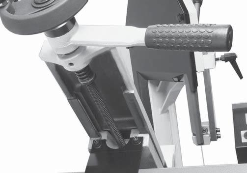
29 Cutting Fluid System FIRE HAZARD! DO NOT cut magnesium when using oil-water solutions as a cutting fluid! Always use a cutting fluid intended for magnesium. The water in the solution will cause a magnesium-chip fire. 4. ON, Figure12 Note: Cutting Fluid Page 26 To use the cutting fluid system: Figure 11 Figure12 NOTICE Keep the screen clear so cutting fluid can recycle to the pump reservoir. NEVER operate the pump with the reservoir below the low mark or you will over-heat the pump and void your warranty! 5. Figure11
30
31
32
33
34
35
36
37


38


39
40
41
42
43
44
45
46
47
48
49
50
51
52
53
54
55
56
57
58
59
60
61
62
63
64 Parts List (G0613) REF PART # DESCRIPTION REF PART # DESCRIPTION 100 P VISE JAW ADJUSTABLE ROD 131 P HEX NUT M P RETAINER 132 P HEX BOLT M X P SWIVEL ARM 133 P HEX PLUG 3/8PT P HEX BOLT M X P CAP SCR M6-1 X P HEX NUT M P LOCK WASHER 6MM 104 P HEX BOLT M X P PUMP 110V, SINGLE PHASE 105 P DISTANCE SET ROD P COOLANT HOSE 106 P KNOB NUT M P CYLINDER BRACKET 107 P BRACKET 143 P CYLINDER 108 P PHLP HD SCR M6-1 X P CAP SCREW M X P BALL BEARING P CAP SCREW M X P BUSHING 180 P BUTTON HD CAP SCR M X P BEARING COVER 181 P FLAT WASHER 8MM 112 P SPANNER NUT M30 X P HANDWHEEL 113 P CAP SCREW M6-1 X P ROLL PIN 114 P LOCK WASHER 6MM 184 P BEARING COVER 115 P SPRING ANCHOR 185 P BALL BEARING P L-BRACKET 186 P VISE BED 117 P LOCK WASHER 8MM 187 P TENSION SPRING 118 P CAP SCREW M X P BUSHING 119 P PHLP HD SCR M5-.8 X P PHLP HD SCR M6-1 X P SCREEN 190 P VISE JAW BRACKET(FRONT) 121 P BASE 191 P VISE PLATE P BASE CABINET 192 P FLAT HD SCR M X P COVER 193 P SET SCREW M X P SWIVEL PLATE 194 P HEX NUT M P HEX NUT M P O-RING 125 P HEX BOLT M X P FLAT WASHER 8MM 126 P FIXED PLATE 197 P CAP SCREW M X P BUTTON HD CAP SCR M6-1 X P LEADSCREW A 128 P CAP SCREW M X P LEADSCREW LOCK LEVER 129 P NUT 199 P VISE JAW BRACKET(REAR) 130 P ADJUSTABLE HANDLE P GIB G0613/14 Swivel Mast Metal Cutting Bandsaw -53-
65
66
67
68
69
70
71
72
73
74
75
76
77
G0614 Control Box Parts
 READ THIS FIRST Model G0613/G0614 ***IMPORTANT UPDATE*** 192 For Machines Mfd. Since 07/06 and Owner's Manual Revised 12/07 For questions or help with this product contact Tech Support at (570) 546-9663
G0614 Control Box Parts
 G0614 Control Box Parts 247V2 250V3 251V3 252V3-1 246V2 252V3 253V2 256V2 254V2 255V2 257V2 246V2 P0614246V2 FUSE HOUSING GIKO KA FSB102-1-2 V2.07.06 253V2 P0614253V2 ON BUTTON AP-PBF-22-1/0G V2.07.06
Headstock and Bow Breakdown (G0613)
") SECTION 8: PARTS Headstock and Bow Breakdown (G0613) -48- G0613/14 Swivel Mast Metal Cutting Bandsaw Parts List (G0613) 1 PSB64M CAP SCREW M10-1.5 X 25 43 P0613043 HANDLE 2 PW04M FLAT WASHER 10MM 44 P0613044
SECTION 8: PARTS Headstock and Bow Breakdown (G0613) -48- G0613/14 Swivel Mast Metal Cutting Bandsaw Parts List (G0613) 1 PSB64M CAP SCREW M10-1.5 X 25 43 P0613043 HANDLE 2 PW04M FLAT WASHER 10MM 44 P0613044
READ THIS FIRST. For questions or help with this product contact Tech Support at (570) or
 or") READ THIS FIRST Model G0811 ***IMPORTANT UPDATE*** For Machines Mfd. Since 02/16 and Owner's Manual Printed 11/16 For questions or help with this product contact Tech Support at (570) 546-9663 or techsupport@grizzly.com
READ THIS FIRST Model G0811 ***IMPORTANT UPDATE*** For Machines Mfd. Since 02/16 and Owner's Manual Printed 11/16 For questions or help with this product contact Tech Support at (570) 546-9663 or techsupport@grizzly.com
READ THIS FIRST. For questions or help with this product contact Tech Support at (570) or
 or") READ THIS FIRST Model G4002/G4003 ***IMPORTANT UPDATE*** For Machines Mfd. Since December, 2014 and Owner's Manual Printed April, 2014 For questions or help with this product contact Tech Support at (570)
READ THIS FIRST Model G4002/G4003 ***IMPORTANT UPDATE*** For Machines Mfd. Since December, 2014 and Owner's Manual Printed April, 2014 For questions or help with this product contact Tech Support at (570)
SECTION 9: PARTS Cabinet & Base
 SECTION 9: PARTS 5 5-1 48 3 75 90 49 4 91 333 46 47 30 89 88 2 34 33 37 36 78 35 32 326 316 49 42 45 83 84V2 43 1 7 8 9 12 87 10 11 Cabinet & Base 31 17 20 40 39 136 41 135 85 86 8 28 26 18 19 21 19 370
Operating Instructions and Parts Manual. 10 x 16 Horizontal Band Saw Models J-7020, J-7040
 Operating Instructions and Parts Manual 10 x 16 Horizontal Band Saw Models J-7020, J-7040 JET 427 New Sanford Road LaVergne, Tennessee 37086 Part No. M-414472 Ph.: 800-274-6848 Revision C2 03/2014 www.jettools.com
READ THIS FIRST. For questions or help with this product contact Tech Support at (570) or
 or") READ THIS FIRST Models G0453, G0453Z, G0454, G0454Z ***IMPORTANT UPDATE*** For Machines Mfd. Since 09/17 and Owner's Manuals Revised 11/12 For questions or help with this product contact Tech Support at
READ THIS FIRST Models G0453, G0453Z, G0454, G0454Z ***IMPORTANT UPDATE*** For Machines Mfd. Since 09/17 and Owner's Manuals Revised 11/12 For questions or help with this product contact Tech Support at
READ THIS FIRST. For questions or help with this product contact Tech Support at (570) or
 or") READ THIS FIRST Model G0668 ***IMPORTANT UPDATE*** For Machines Mfd. Since June, 2008 and Owner's Manual Printed February, 2008 For questions or help with this product contact Tech Support at (570) 546-9663
READ THIS FIRST Model G0668 ***IMPORTANT UPDATE*** For Machines Mfd. Since June, 2008 and Owner's Manual Printed February, 2008 For questions or help with this product contact Tech Support at (570) 546-9663
Base/Stand Model G9743 (Mfg. since 12/07) V V2 86V V2 89V
 V V2 86V V2 89V") SECTION 9: PARTS 97 364 102 101 33 34 32 29 31 30 366 96 83 372 367 368 365 100 99 98 370 369 95 28 374 377 373 376 375 77 68 94 95 87V2 93 Base/Stand 1 2 62 61 78 26 27 15 16 17 79 25 76 88V2 9 21 18
SECTION 9: PARTS 97 364 102 101 33 34 32 29 31 30 366 96 83 372 367 368 365 100 99 98 370 369 95 28 374 377 373 376 375 77 68 94 95 87V2 93 Base/Stand 1 2 62 61 78 26 27 15 16 17 79 25 76 88V2 9 21 18
READ THIS FIRST. For questions or help with this product contact Tech Support at (570) or
 or") READ THIS FIRST Model G0728-31 ***IMPORTANT UPDATE*** For Machines Mfd. Since 01/17 and Owner's Manual Revised 09/14 For questions or help with this product contact Tech Support at (570) 546-9663 or techsupport@grizzly.com
READ THIS FIRST Model G0728-31 ***IMPORTANT UPDATE*** For Machines Mfd. Since 01/17 and Owner's Manual Revised 09/14 For questions or help with this product contact Tech Support at (570) 546-9663 or techsupport@grizzly.com
Parts Breakdown G4030
 Parts Breakdown G4030 G4030 6 1 2" x 10" Metal-Cutting Bandsaw -35- Parts Breakdown G4030-36- G4030 6 1 2" x 10" Metal-Cutting Bandsaw Parts Breakdown G4030 G4030 6 1 2" x 10" Metal-Cutting Bandsaw -37-
SECTION 9: PARTS. Electrical REF PART # DESCRIPTION REF PART # DESCRIPTION
 SECTION 9: PARTS Electrical 1 P4002001 START BUTTON 52 P4002052 CONTACTOR GSC1CJX4-D 110V 2 P4002002 INDICATOR LIGHT 53 P4002053 CONTACTOR JZC3-40D 110V 3 P4002003 JOG BUTTON 54 P4002054 FUSE HOLDER 4
READ THIS FIRST. For questions or help with this product contact Tech Support at (570) or
 or") READ THIS FIRST Model G5912Z/G7214Z/G8621 ***IMPORTANT UPDATE*** For Machines Mfd. Since 1/17 and Owner's Manual Printed 2001 For questions or help with this product contact Tech Support at (570) 546-9663
READ THIS FIRST Model G5912Z/G7214Z/G8621 ***IMPORTANT UPDATE*** For Machines Mfd. Since 1/17 and Owner's Manual Printed 2001 For questions or help with this product contact Tech Support at (570) 546-9663
IMPORTANT: Chuck guard MUST be installed before drill chuck!
 IMPORTANT: Chuck guard MUST be installed before drill chuck! Model G7945/G7946 ***IMPORTANT UPDATE*** For Machines Mfg. Since December, 2012 and Owner's Manual Revised August, 2009 The following changes
SECTION 9: PARTS. Headstock A 126A 127A-1 REF PART # DESCRIPTION REF PART # DESCRIPTION
 SECTION 9: PARTS Headstock 120 121 113 115 112 111 110 109 108 105 106 107 135 101 119A 121 120 118 114 115 107 106 104 123 122 118 114 126A 105 126 103 102 126B 127A-1 131 127A 124 133 134 126C 129 130
SECTION 9: PARTS Main
 -64- Model G0765 (Mfd. Since 5/15) 1 2 3 4 5 6 7 8 9 9 10 10 11 11 12 12 13 14 15 16 17 18 19 20 21 21 22 23 23 24 25 26 27 28 29 30 31 32 33 35 36 37 38 39 40 41 42 43 44 44 45 157 46 47 48 49 50 50 51
SECTION 9: PARTS. Accessories
 SECTION 9: PARTS Accessories 2 1 1-1 1-2 3 4 39 138 35 135 40 34 33 7 6 401V2 36 36-3 36-2 28 29 30 27 26 31 32 25 22 24 23 16-21 15 14 10 11 9 13 12 36-1 37 38 1 P4003G0001 4-JAW INDEPENDENT CHUCK ASSEMBLY
ST1014 PARTS ST1014 Headstock Breakdown
 ST1014 PARTS ST1014 Headstock Breakdown 112 114 23 104 105 108 102 106 20 19 21 22 101 100 103 111 38 14 15 37 46 44 47 45 107 93 39 41 40 67 110 109 74 75 76 11 12 13 9 8 6 10 31-2 31-3 3 2 7 26 24 31-1
SECTION 9: PARTS. Accessories
 SECTION 9: PARTS Accessories 2 1 1-1 1-2 3 4 39 138 35 135 40 34 33 7 6 5 401V2 36 36-3 36-2 28 29 30 27 26 31 32 25 22 24 23 16-21 15 14 10 11 9 13 12 36-1 37 38 1 P4003G0001 4-JAW INDEPENDENT CHUCK ASSEMBLY
SECTION 10: PARTS. Headstock
 33 32 31 30 7 SECTION 10: PARTS 34 23 36 22 15 14 12 35 37 48 39 41 42 50 40 25 38 38 26 39 42 44 41 25 26 40 51 43 52 10 5 53 9 4 1 27 2 21 19 20 Headstock 8 16 11 17 18 14 13 7 6 45 47 46 3 1 P0768001
READ THIS FIRST. For questions or help with this product contact Tech Support at (570) or
 or") READ THIS FIRST Model G0503 ***IMPORTANT UPDATE*** For Machines Mfd. Since 11/06 and Owner's Manual Revised 05/11 For questions or help with this product contact Tech Support at (570) 546-9663 or techsupport@grizzly.com
READ THIS FIRST Model G0503 ***IMPORTANT UPDATE*** For Machines Mfd. Since 11/06 and Owner's Manual Revised 05/11 For questions or help with this product contact Tech Support at (570) 546-9663 or techsupport@grizzly.com
SECTION 9: PARTS Jointer Breakdown
 Model G0490/G0490X (Mfd. Since 8/12) -49-1 3 8 7 9 12 14 15 16 18 21 23 24 24 28 29 32 33 37 38 38 44 45 49 50 51 53 55 56 57 58 59 61 60 64 65 66 68 72 75 80 81 82 83 84 85 86 87 88 90 91 92 94 93 96
PARTS Stand Breakdown
 PARTS Stand Breakdown 35-5 35-2 35-4 63 1 2 3 4 5 35-1 35-3 36 37 38 39 35 34 33 32 30 28 6 7 8 21 29 23 22 27 26 25 24 42 43 44 45 46 47 9 10 62 61 60 51 11 59 19 18 12 12 13 58 14 57 15 56 55 54 53 52
SECTION 9: PARTS Main
 SECTION 9: PARTS Main 58 63 67 66 65 67 66 59 58 49 58 48 49 61A 61 64 62 55 50 35-3 34 35-1 57 56 41 42 151 51 50 33A 35-2 30A 30A-1 35 38 39 31 32 18 40 43 44 68 51 41 45 46 57 56 55 47 152 153 20 21
MODEL G0760 8" X 29" MILL/DRILL w/stand & POWER FEED MANUAL INSERT
 MODEL G0760 8" X 29" MILL/DRILL w/stand & POWER FEED MANUAL INSERT The Model G0760 is the same machine as the Model G0705 except the Model G0760 has an X-axis table power feed. Except for the differences
SECTION 10: PARTS. Headstock
 33 32 31 30 7 SECTION 10: PARTS 34 23 36 22 15 14 12 35 37 48 39 41 42 50 40 25 38 38 26 39 42 44 41 25 26 40 51 43 52 10 5 53 9 4 1 27 2 21 19 20 Headstock 8 16 11 17 18 14 13 7 6 45 47 46 3 1 P0768001
Exploded View Saw Base - Model 7060 Semi-Automatic Cut-Off Band Saw
 Exploded View Saw Base - Model 7060 Semi-Automatic Cut-Off Band Saw 136 137 135 134 132 131 133 113 114 115 117 116 118 119 120 121 79 78 77 107 108 65 76 110 109 66 10 9 6 11 5 4 8 7 75 74 73 72 111 112
SECTION 9: PARTS Headstock Case and Shift
 SECTION 9: PARTS Headstock Case and Shift 3 1 2 10-1 10-2 8 9 10 6 7 19 10-3 15 11 12 25 16 17 18 14 13 12 32 26 29 20 21 33 34 27 35 37 28 43 22 38 39 40 31 45 28 43 23 41 5 28 43 44 30 36-80- Model G0709
READ THIS FIRST. The following changes were recently made to these machines since the owner's manual was printed:
 READ THIS FIRST Model G0609/G0609X ***IMPORTANT UPDATE*** For Machines Mfg. Since August, 2012 and Owner's Manual Revised February, 2008 The following changes were recently made to these machines since
SECTION 9: PARTS. Table Breakdown REF PART # DESCRIPTION REF PART # DESCRIPTION
 SECTION 9: PARTS Table Breakdown 1 2 3 4 5 6 7 8 9 10 11 12 13 14 15 16 17 18 19 20 21 22 23 24 23 25 17 26 27 8 1 P0675001 CAP SCREW M8-1.25 X 30 15 P0675015 SUPPORT BLOCK 2 P0675002 TABLE SUPPORT BLOCK
SECTION 9: PARTS Main
 63 58 62 61A 66 65 67 66 67 58 58 59 64 SECTION 9: PARTS 162 161 Main 160 45 152 21 20 17 153 166 33 30A 31 32 135 144 133 136 34 35-2 35-3 131 16 130 134 139 15 35-1 137 14V2 151 140 38 143 150 18 142
Main Parts. -6- Model G0555LA35 (Mfd. Since 10/17) 30A V
 30A V") 60 49 50 76 41 65 66 44 46 43 42 47 51 63 58 64 59 48 62 16 61V2 50 51 55 56 57 70 49 69 64 55 56 43 57 167 154 41 40 8 22 30A 44 45 3 4 Main Parts 14 15 16 7 168 155 30 195 34 194 186 6 68 24 115 116
60 49 50 76 41 65 66 44 46 43 42 47 51 63 58 64 59 48 62 16 61V2 50 51 55 56 57 70 49 69 64 55 56 43 57 167 154 41 40 8 22 30A 44 45 3 4 Main Parts 14 15 16 7 168 155 30 195 34 194 186 6 68 24 115 116
SECTION 10: PARTS Body
 -76- Model G0690/G0691 (Mfd. 6/15+) SECTION 10: PARTS 55V2 55-1 55-2 55-3V2 55-5 55-6 8 9 9 56 10 10 68 69 70 71 55-4 1 2 3 4 5 6 7 8 9 14 15 18 19 20 21 22 23 24 25 26 27 27 28 29 30 31 32 32 33 33 34
G8145Z Cabinet Breakdown & Parts List
 PROG FUN DATA KEYPAD RPM T.S MPM RUN STOP RESET G8145Z Cabinet Breakdown & Parts List 14 11 12 16 18 8 10 15 17 9 13 21 22 19 20 24 25 7 4 3 5 6 23 2 19 20 27 28 26 1 1 P8145Z001 WHEEL DOOR LOWER 15 P8145Z015
G8146Z Cabinet Breakdown & Parts List
 PROG FUN DATA KEYPAD RPM T.S MPM RUN STOP RESET G8146Z Cabinet Breakdown & Parts List 29 30 31 32 35 33 34 14 16 18 11 12 10 8 15 17 9 13 22 21 19 20 24 25 4 4-1 7 4-2 4-4 3 2 5 4-3 6 19 20 23 27 28 26
SECTION 9: PARTS Stand/Brake/Coolant Pump
 SECTION 9: PARTS Stand/Brake/Coolant Pump 8-1 18 3 4 2 8 7 20 6 5 19 7 1 17 23 42 22 21 25 24 31 62 26 27 29 28 30 55 5 56 57 32 33 66 60 61 63 64 22 9 54 53 2 10 10 2 11 10 16 9 58 10 67 10 34 65 35 36
Main Breakdown. Model G0531B/G0566B V2 (G0531B) 80V2-2
 80V2-2") Main Breakdown 53 85-1 54 59 54 56 54 52 55 57 175 53 56 85 29 119-2 114 89 22 119-2 119 107 119-5 119-3 119-6 119-1 29 22 119-4 114 112 96 113 114 100 116 117 105 120 102 103 108 115 99 98 92 91 90 73
Main Breakdown 53 85-1 54 59 54 56 54 52 55 57 175 53 56 85 29 119-2 114 89 22 119-2 119 107 119-5 119-3 119-6 119-1 29 22 119-4 114 112 96 113 114 100 116 117 105 120 102 103 108 115 99 98 92 91 90 73
MODEL G0501 SLIDING TABLE SAW
 MODEL G0501 SLIDING TABLE SAW MANUAL UPDATE The Sliding Table Saw has changed slightly from when the manual was originally written. We have improved the crosscut fence, extension tables, blade guard assembly,
SECTION 9: PARTS Table
 SECTION 9: PARTS Table 33 We do our best to stock replacement parts when possible, but we cannot guarantee that all parts shown are available for purchase. Call (800) 523-4777 or visit www.grizzly.com/
D('00 D]^ ('&'. G8IKJ
![D('00 D]^ ('&'. G8IKJ](/thumbs/90/103707123.jpg "D('00 D]^ ('&'. G8IKJ") 1 2 5 6 7 8 11 12 10 13 14 15 27 28 16 26 29 30 25 17 19 20 22 21 32 23 24 31 42 43 33 34 40 41 35 49 36 37 51 52 53 44 45 46 47 38 39 48 18-40- 1 XM1099001 CONTROL PANEL FACE 29 XPCAP50M CAP SCREW M5-.8
1 2 5 6 7 8 11 12 10 13 14 15 27 28 16 26 29 30 25 17 19 20 22 21 32 23 24 31 42 43 33 34 40 41 35 49 36 37 51 52 53 44 45 46 47 38 39 48 18-40- 1 XM1099001 CONTROL PANEL FACE 29 XPCAP50M CAP SCREW M5-.8
G0513X2 Main -87- G0513 Series Bandsaws 82V V2 82-6V2 95A V2 82-5V2 82-1V2 82-4V V A
 G0513X2 Main 23 55 22 48 17 17-1 17-2 21 7 17-3 17-2 17-4 24 17-5 18-5 22 24 21 55A 50 8 9 49 11 12 13 14 15 47 16 10 46 45 3 44 43 39 38 37 39 40 32 33 36 42 34 35 2 25 28 18-4 18-2 18-3 31 30 29 18-1
SECTION 9: PARTS G0513/G0513P/G0513ANV
 SECTION 9: PARTS G0513/G0513P/G0513ANV Main 21 22 23 82-6 82-5 48 22 19 20 24 18 17 24 17 26 21 55 17 16 14 15 32 33 34 20 18 27 25 50 13 47 18 82-1 175 35 55A 49 9 11-1 10 46 45 11 12 44 176 39 38 37
READ THIS FIRST. For questions or help with this product contact Tech Support at (570) or
 or") READ THIS FIRST Model G5912Z/G7214Z/G8621 ***IMPORTANT UPDATE*** For Machines Mfd. Since 1/17 and Owner's Manual Printed 2001 For questions or help with this product contact Tech Support at (570) 546-9663
READ THIS FIRST Model G5912Z/G7214Z/G8621 ***IMPORTANT UPDATE*** For Machines Mfd. Since 1/17 and Owner's Manual Printed 2001 For questions or help with this product contact Tech Support at (570) 546-9663
G0513X2 Main. G0513 Series Bandsaws (Mfd. Since 07/18) A V2
 A V2") G0513X2 Main 55 17 48 7 16 55A 14 15 49 13 47 50 12 10 71 70 72 73 59 69 74 46 11 9 8 76 5 75 4 68 81 80 67 66 48 50 39 78 79 23 17-3 17-2 17-1 17-4 17-2 21 22 24 17-5 32 33 34 35 28 2 45 3 38 44 39 43
G0513X2 Main 55 17 48 7 16 55A 14 15 49 13 47 50 12 10 71 70 72 73 59 69 74 46 11 9 8 76 5 75 4 68 81 80 67 66 48 50 39 78 79 23 17-3 17-2 17-1 17-4 17-2 21 22 24 17-5 32 33 34 35 28 2 45 3 38 44 39 43
SECTION 9: PARTS. Headstock
 SECTION 9: PARTS We do our best to stock replacement parts when possible, but we cannot guarantee that all parts shown are available for purchase. Call (800) 52-4777 or visit www.grizzly.com/parts to check
GEAR HEAD METAL LATHE
 GEAR HEAD METAL LATHE MODEL G4002 / G4003 PARTS LIST COPYRIGHT 2000 BY GRIZZLY INDUSTRIAL, INC. WARNING: NO PORTION OF THIS MANUAL MAY BE REPRODUCED IN ANY SHAPE OR FORM WITHOUT THE WRITTEN APPROVAL OF
Coolant Tank Screen Leg Idle End Lockwasher 64 B-015B Leg Drive End Machine Screw 1/4-20 x 3/4 Round Head
 Always give model number, serial number and part number when ordering repair parts. BED, COOLANT & DASH POT PARTS LIST (Cont'd.) REF NO. PART NUMBER DESCRIPTION 19 B-077 Vise Slide Block 20 B-045 Vise
Horizontal Band Saw. Operating Instructions and Parts Manual. Models EHB-1018VM EHB-1018VMH
 Operating Instructions and Parts Manual Horizontal Band Saw Models EHB-08VM EHB-08VMH JET 427 New Sanford Road LaVergne, Tennessee 37086 www.jettools.com Ph.: 855-336-4032 Part No. M-89070 REV B2 08/204
M1014 7" x 12" Metal Cutting Bandsaw PARTS -38-
 14 13 15 16 18 17 55 10 12 11 19 54 9 20 53 7 5 4 60 7 3 1 28 6 2 61 23 27 26 29 21 24 25 22 32 32 33 35 36 37 38 49 48 47 40 39 34 30 59 51 52 46 45 44 43 42 42 41 50 56 57 58-38- Parts List 1 XM1014001
Headstock Gear System
 Headstock Gear System (0000 Series Parts) 10 7 6 5 4 3, 2 16 11 12 13 14 15 9,8 1 90 17 18 19 20 21 22 23 24 25 26 27 28 29 30 31 32 33 34 91 93 94 95 96 97 98 99 100 102 104 106 108 109 92 101 103 105
READ THIS FIRST Models G0544/G5850Z/ G5851Z/G7213Z
 READ THIS FIRST Models // G5851Z/G7213Z ***IMPORTANT UPDATE*** For Machines Mfd. Since 12/16 and Owner's Manual Revised 03/06 For questions or help with this product contact Tech Support at (570) 546-9663
SECTION 9: PARTS G0453Z
 parts breakdown SECTION 9: PARTS G0453Z Headstock Breakdown 4 3 2 20 26 104 21 19 23 22 24 99 97 98 25 94 95 93 14 15 39 40 107 86 41 42 45 62 30 66 61 60 13 9 10 12 11 27 31 33 34 35 73 77-1 77 36 3738
SECTION 9: PARTS. Accessories 2-1
 SECTION 9: PARTS Accessories 2-2 3 1 1-3 1-1 2 2-1 5 12 1-2 13 11 31 10 9 7 6 4 15 8 14 19 20 21 23 24 28 29 30 18 17 16 25 27 1 P0750G0001 3-JAW CHUCK ASSEMBLY 6" D1-5 SCROLL 13 P0750G0013 DRL CHK KEY
The following change was recently made since the owner's manual was printed:
 READ THIS FIRST Model G0531B/G0566B/ G0568/G0569 ***IMPORTANT UPDATE*** For Machines Mfd. Since 08/04 and Owner's Manual Revised 05/15 For questions or help with this product contact Tech Support at (570)
Trajan 1319ADR Fabricating Saw Parts and Service Manual Order Parts From
 www.trajansaw.com Trajan 1319ADR Fabricating Saw Parts and Service Manual Order Parts From www.bandsawparts.com 713-884-1101 CODE_NO PART_NO DESCRIPTION SPECIFICATION QTY 1S 103005AS Stand 1.00 2 103009
SECTION 9: PARTS. Electrical Box. (0000 Series Parts) 0000 Series Parts List
 0000 Series Parts List") SECTION 9: PARTS Electrical Box (0000 Series Parts) 0000 Series Parts List 1 P04920001 CONTACTOR 6 P04920006 FUSE 2A (LC1-D0910, B5, 24V, 50HZ) 7 P04920007 FUSE HOUSING 2 P04920002 CONTACTOR 8 P04920008
SECTION 9: PARTS Electrical Box (0000 Series Parts) 0000 Series Parts List 1 P04920001 CONTACTOR 6 P04920006 FUSE 2A (LC1-D0910, B5, 24V, 50HZ) 7 P04920007 FUSE HOUSING 2 P04920002 CONTACTOR 8 P04920008
HYDRAULIC CONTROL DETAILS PARTS LIST
 Always give model number, serial number and part number when ordering repair parts. HYDRAULIC CONTROL DETAILS PARTS LIST REF NO. PART NUMBER DESCRIPTION 1 101939 Hydraulic Tank 2 101940 Hydraulic Tank
READ THIS FIRST. The following changes were recently made to these machines since the owner's manual was printed:
 READ THIS FIRST Model G0656/P/PX/X ***IMPORTANT UPDATE*** For Machines Mfg. Since April, 2014 & Owner's Manual Printed September, 2009 The following changes were recently made to these machines since the
MODEL G0604X 6" EXTREME SERIES PARALLELOGRAM JOINTER MANUAL INSERT
 MODEL G0604X 6" EXTREME SERIES PARALLELOGRAM JOINTER MANUAL INSERT The Model G0604X is the same as the Model G0604, except it has a 1 1 2 HP 110/220V motor. Besides the data sheet, parts, and wiring diagram
MODEL G0632Z 16" X 42" VARIABLE- SPEED WOOD LATHE MANUAL INSERT
 MODEL G0632Z 16" X 42" VARIABLE- SPEED WOOD LATHE MANUAL INSERT The Model G0632Z is the same machine as the Model G0632 except it has a higher full-load current rating, a different inverter and inverter
535A. Main Components. Pipe and Bolt Threading Machine. Printed in U.S.A. Ridge Tool Company/Elyria, Ohio, U.S.A.
 Pipe and Bolt Threading Machine A Main Components 0 Screw, Button Head /" - 0 x /" () Washer, Flat /" ()" Top Cover 0 Base Bottom Cover Screw, Pan Head # - x " () Carriage Assembly 0 Front Support Bar
MODEL T10815 GRINDING ATTACHMENTS INSTRUCTIONS
 MODEL T10815 GRINDING ATTACHMENTS INSTRUCTIONS For questions or help with this product contact Tech Support at (570) 546-9663 or techsupport@grizzly.com Introduction Designed to work exclusively with the
MODEL G0759 MILL/DRILL w/stand & DRO MANUAL INSERT
 MODEL G0759 MILL/DRILL w/stand & DRO MANUAL INSERT The Model G0759 is the same machine as the Model G0704 except the Model G0759 has a 3-axis DRO. Besides the differences noted in this insert, all other
SECTION 9: PARTS G7945/G7946
 SECTION 9: PARTS G7945/G7946 Main Parts 22 53 25 26 31 139 32 32-1 60 38 59 38-1 119 35 37 31 38-3 124 125 45A-2 45A-4 45A-1 31 60 45A-3V2 120 121 62 28 28-1 28 27 34 50 51 39 41 126 137 36 46 40 63 33
SECTION 9: PARTS G0514X
 SECTION 9: PARTS G0514X Main 48 23 24 21 55 17 19 22 24 50 49 3 22 26 17 21 15 14 16 13 46 47 10 32 7 38 33 3435 37 12 44 45 41 42 43 11 40 8 39 165 166 1 11-1 29 30 25 28 26 27 5 4 58 57 64 65 56 68 62
SECTION 9: PARTS Column Breakdown
 SECTION 9: PARTS Column Breakdown 3 4 5 6 7 8 12 2 1 9 10 11 20 21 13 14 15 18 16 17 25 26 27 28 29 3 31 31-1 32 33 34 35 36 37 39 38 47 48 46 45 3644 44 43 40 41 42 24 23 22 52 51 50 30 49 57 58 59 60
SECTION 9: PARTS Fence & Cutterhead
 (G0855 Only) (G0856 Only) SECTION 9: PARTS Fence & Cutterhead 1 2 3 4 65 6 5 23 111 111 7 27 130 131 132 133 136 134 135 117 12 40 8 9 13 10 9 14 15 8 11 18 25 29 63 19 20 21 17 22 28 26 26 24 40-3 40-2
SECTION 10: PARTS G1023RL
 SECTION 10: PARTS 131 132 133 G1023RL (All) Main 121 118 119 128 126 125 124 123 124 122 120 119 128 116 6V2 5 4V2 4-1 129 127 128 117 26V3 26-3V2 26-1 6-2 (G1023RLWX) 26-2 26-4V3 7 6-1 1 (G1023RL) 19-1
POWER FEEDER MODEL G1128 AND MODEL G1129 PARTS LIST
 POWER FEEDER MODEL G1128 AND MODEL G1129 PARTS LIST COPYRIGHT 1995 BY GRIZZLY IMPORTS, INC. WARNING: NO PORTION OF THIS MANUAL MAY BE REPRODUCED IN ANY SHAPE OR FORM WITHOUT THE WRITTEN APPROVAL OF GRIZZLY
Main Breakdown. ST " Bandsaw -41-
 Main Breakdown ST1000 14" Bandsaw -41- Main Breakdown Parts List REF PART # DESCRIPTION REF PART # DESCRIPTION 1 XST1000001 MOTOR 3/4HP 110/220V 48 XPHTEK4M TAP SCREW M4 X 8 1-1 XST1000001-1 FAN COVER
1822-I. Spindle Assembly. Pipe and Bolt Threading Machine. Ridge Tool Company/Elyria, Ohio, U.S.A. 2* 3 4 5* * *
 -I Pipe and Bolt Threading Machine Spindle Assembly * * * 0 * * * 0 * * 0* * * Rear Cover * Screw () * Washer () Top Cover w/clips (Includes,, ) * J Clip () Front Cover * Screw () Pivot Rod Support ()
SECTION 9: PARTS. Table. Spiral Cutterhead For Model G0452Z Cutterhead For Models G0452/P Model G0452/P/Z (Mfg.
 SECTION 9: PARTS Table 17 18 19 87 86 21 262-3 262-1 262-2 27 28 29 30 22 23 24 35 36 37 38 262 25 26 2 13 Cutterhead For Models G0452/P 10 45 12 13 7 8 9 50A 6 11 31 14 15 16 12 13 81 82 83 84 32 85 33
ST1007/ST1012 PARTS ST1007
 ST1007/ST1012 PARTS ST1007 Main Breakdown 30-7 30-8 30-10 30-9 30-1 30-3 30-6 30-2 30-4 30-5 82 83 84 77 78 79 80 30 60 59 58 62 64 61 46 44 63 66 65 55 56 26 45 27 45 27 25 43 37 41 50 42 72 73 51 53
SECTION 9: PARTS. G9860/G9860ZX Cabinet Breakdown & Parts List
 MIN SECTION 9: PARTS G9860/G9860ZX Cabinet Breakdown & Parts List 9 33 34 5 11 237V4 236V2 10 23 32 17 12 13 16 POWER STOP 5000 15 14 17 31 27 35 30 17 26 3 1 33 34 1 P9860001 BASE 17 PS68M PHLP HD SCR
PARTS. W1669 & W1670 Parts PARTS. Model W1669/W1670 (For Machines Mfd. Since 04/18) 66V A A A 28A
 66V A A A 28A") W1669 & W1670 Parts 23 66V2 22 21 25 26 53A 62 63 89 64 9 65 24 20 15 16A 54 93 10 16A-1 81 77 94 53 79 102 103 28 36 8 30 19 31 32 32-1 109 28A 28 27 34 33 56 49 76 76 19-3 19-1 19-2 38-1 89 35 60 59
W1669 & W1670 Parts 23 66V2 22 21 25 26 53A 62 63 89 64 9 65 24 20 15 16A 54 93 10 16A-1 81 77 94 53 79 102 103 28 36 8 30 19 31 32 32-1 109 28A 28 27 34 33 56 49 76 76 19-3 19-1 19-2 38-1 89 35 60 59
BUY PARTS ONLINE AT GRIZZLY.COM!
 SECTION 9: PARTS Tables, Fence & Cutterhead 28 29 26 27 25 23 23 22 24 22 35 37 36 38 16 15 17 18 39 11 14 19 20 21 13 12 6 7 8 9 10 1 2 5 49 3 4 3 31 30 6 7 94 93 95 40 96 43 42 44 45 46 47 48 55 55-4
SECTION 10: PARTS. Body
 SECTION 10: PARTS Body 1 P0715P001 EXTENSION WING 17 PS14M PHLP HD SCR M6-1 X 12 2 PCAP88M CAP SCREW M10-1.25 X 25 18 PLW03M LOCK WASHER 6MM 3 PLW06M LOCK WASHER 10MM 19 PWF06M FENDER WASHER 6MM 4 PW04M
SECTION 11: PARTS Main
 SECTION 11: PARTS Main 55 48 21 20 22 7 18 19 23 17 17 18 21 22 14 15 16 32 33 34 26 27 50 49 13 47 35 2 18 20 55A 12 11 8 10 45 46 3 38 37 44 53 36 51 42 25 30 29 28 43 99 103 98 100 52 101 5 4 58 57
Number Wheeler P/N Description Set Rex P/N Notes Base 1 J Support, Right 1 J Support, Left 1 J Nut (M8)
") 1 603500 Base 1 J001 2 603501 Support, Right 1 J002 3 603502 Support, Left 1 J003 4 600328 Nut (M8) 4 5 600130 Spring Washer (8mm) 4 6 600344 Roll Pin (M6x30) 4 7 600129 Socket Hd Cap Screw (M8x25) 4 8
1 603500 Base 1 J001 2 603501 Support, Right 1 J002 3 603502 Support, Left 1 J003 4 600328 Nut (M8) 4 5 600130 Spring Washer (8mm) 4 6 600344 Roll Pin (M6x30) 4 7 600129 Socket Hd Cap Screw (M8x25) 4 8
SECTION 9: PARTS. Table & Column Breakdown
 SECTION 9: PARTS Table & Column Breakdown Table & Column Parts List 201 P1126201 TABLE HANDWHEEL 230 P1005603 LIMIT STOP SLEEVE 205 P1126205 LEADSCREW ASSY M23.5-2.5 X 468 2121 P11262121 INDICATOR PLATE
Trajan 270 European Style Parts and Service Manual Order Parts From
 www.trajansaw.com Trajan 270 European Style Parts and Service Manual Order Parts From www.bandsawparts.com 713-884-1101 1 198005 Body Frame 1 2 198008 Anchor Block 1 2A 198151 Anchor Plate 1 2B HT001 Round
Model W1819/W1820 (Mfg. Since 09/11) PARTS. Body V V PARTS -79-
 PARTS. Body V V PARTS -79-") -79- Model W1819/W1820 (Mfg. Since 09/11) 155V2 155-1 155-2 155-3V2 155-6 155-5 108 109 109 156 110 110 168 169 170 171 101 102 103 104 105 106 107 108 109 114 115 118 119 120 121 122 123 124 125 126 127
-79- Model W1819/W1820 (Mfg. Since 09/11) 155V2 155-1 155-2 155-3V2 155-6 155-5 108 109 109 156 110 110 168 169 170 171 101 102 103 104 105 106 107 108 109 114 115 118 119 120 121 122 123 124 125 126 127
Column & Stand. -4- Model G0759 (Mfd. Since 1/14)
") Column & Stand 3 4 5 6 7 8 12 2 1 9 10 11 20 21 13 14 15 18 16 17 25 3 26 27 28 29 31 31-1 32 33 34 47 46 45 3644 48 35 36 37 39 43 44 42 38 40 41 412 24 23 22 52 51 50 30 49 412-2 412-1 57 58 39 59 60
Column & Stand 3 4 5 6 7 8 12 2 1 9 10 11 20 21 13 14 15 18 16 17 25 3 26 27 28 29 31 31-1 32 33 34 47 46 45 3644 48 35 36 37 39 43 44 42 38 40 41 412 24 23 22 52 51 50 30 49 412-2 412-1 57 58 39 59 60
MODEL T28173/T28174 ROLLER TABLES INSTRUCTIONS
 MODEL T28173/T28174 ROLLER TABLES INSTRUCTIONS FOR MODELS MFD. SINCE 10/17 For questions or help with this product contact Tech Support at (570) 546-9663 or techsupport@grizzly.com Rails Rollers Reversible
PARTS G9729 Lathe Bed
 PARTS G9729 Lathe Bed 114 132 126 125 131 133 129 128 130 127 139 124 10 124 123 122 135 137 147 144 121 148 146 149 136 138 140 150 152 142 143 141 151 153 21 168 20 19 18 17 162 22 147 13315 14 13131
SECTION 9: PARTS. Table
 SECTION 9: PARTS We do our best to stock replacement parts when possible, but we cannot guarantee that all parts shown are available for purchase. Call (800) 523-4777 or visit www.grizzly.com/parts to
Model W1854 (For Machines Mfd. Since 02/18) PARTS. Main Breakdown 42-1 PARTS -46-
 PARTS. Main Breakdown 42-1 PARTS -46-") 3 144 1 143 119 1 4-1 14 140 13 4 1 1 4 14 11 7 108 134 131 13 14 100 1 8 16 9 80 93 40 14 146 39 Main Breakdown 133 117 130 10 3 19 3 11 10 9 38 9 7 6 4 13 7 134 16 138 141 Model W184 (For Machines Mfd.
3 144 1 143 119 1 4-1 14 140 13 4 1 1 4 14 11 7 108 134 131 13 14 100 1 8 16 9 80 93 40 14 146 39 Main Breakdown 133 117 130 10 3 19 3 11 10 9 38 9 7 6 4 13 7 134 16 138 141 Model W184 (For Machines Mfd.
SECTION 10: PARTS. Body. 440V Conversion Kit
 SECTION 10: PARTS We do our best to stock replacement parts when possible, but we cannot guarantee that all parts shown are available for purchase. Call (800) 523-4777 or visit www.grizzly.com/parts to
MODEL H9565 BALL BEARING GUIDE FOR G0513/G0514 INSTRUCTION SHEET
 MODEL H9565 BALL BEARING GUIDE FOR G0513/G0514 INSTRUCTION SHEET Introduction The Model H9565 replaces the upper and lower Euro-style guides on your G0513 or G0514 Bandsaw. Inventory (Figure 1) A. Upper
SECTION 9: PARTS. Stand REF PART # DESCRIPTION REF PART # DESCRIPTION
 SECTION 9: PARTS Stand 1 2 6 8 3 4 5 7 9 6 13 11 28 27 17 15 14 28 27 17 29 18 20 21 22 26 1 2 4 6 3 5 10 9 12 15 16 12 23 17 25 24 9 21 1 P0716001 HANDLE GRIP 16 P0716016 RIGHT LONG TOP BRACE 2 P0716002
ALUMA-CLASSIC FENCE W1716 & W1720 INSTRUCTION MANUAL
 ALUMA-CLASSIC FENCE W1716 & W1720 INSTRUCTION MANUAL Phone: Phone: 1-360-734-3482 On-Line On-Line Technical Technical Support: Support: tech-support@woodstockint.com tech-support@shopfox.biz COPYRIGHT
SECTION 8: PARTS Cabinet Breakdown
 SECTION 8: PARTS Cabinet Breakdown G0641 Double Miter Saw -39- Cabinet Parts List 1 P0641001 SAFETY HOOD 17 PB03M HEX BOLT M8-1.25 X 16 2 P0641002 FRONT GUARD 18 PW01M FLAT WASHER 8MM 3 PW01M FLAT WASHER
PARTS. Base Cabinet & Motor PARTS. Model W1745W (For Machines Mfd. Since 9/16) V2 22V2-3 22V2-4 22V2-1 22V2-2
 V2 22V2-3 22V2-4 22V2-1 22V2-2") Model W1745W (For Machines Mfd. Since 9/16) Base Cabinet & Motor 22V2-1 22V2-2 22V2-5 22V2-9 22V2-8 22V2-7 22V2-6 22V2-3 22V2-4 22V2 23 24 26 25 46 47 48 49 44 45 15 14 16 17 50 18 13 12 11 7 20 9 8 9
Model W1745W (For Machines Mfd. Since 9/16) Base Cabinet & Motor 22V2-1 22V2-2 22V2-5 22V2-9 22V2-8 22V2-7 22V2-6 22V2-3 22V2-4 22V2 23 24 26 25 46 47 48 49 44 45 15 14 16 17 50 18 13 12 11 7 20 9 8 9
HEADSTOCK (CASTNG & CONTROLS)
") HEADSTOCK (CASTNG & CONTROLS) REF.NO. PART NO. DESCRIPTION Q'TY 1 VE2101 HEADSTOCK CASTING 1 2 VE2134 HEADSTOCK COVER 1 3 VE2116 SHAFT 1 4 VE2117 GEAR 1 5 VE2118 WASHER 1 6 VE2119 SHAFT 1 7 VE2120 GEAR
HEADSTOCK (CASTNG & CONTROLS) REF.NO. PART NO. DESCRIPTION Q'TY 1 VE2101 HEADSTOCK CASTING 1 2 VE2134 HEADSTOCK COVER 1 3 VE2116 SHAFT 1 4 VE2117 GEAR 1 5 VE2118 WASHER 1 6 VE2119 SHAFT 1 7 VE2120 GEAR
MODELS W1723 and W " PLANERS PARTS LIST
 MODELS W1723 and W1724 15" PLANERS PARTS LIST Phone: 1-360-734-3482 On-Line Technical Support: tech-support@shopfox.biz COPYRIGHT DECEMBER, 2003 BY WOODSTOCK INTERNATIONAL, INC. WARNING: NO PORTION OF
G0604 6" X 56" Jointer -43- Jointer Parts Breakdown
 G0604 6" X 56" Jointer -43- Jointer Parts Breakdown Jointer Parts List 1 P0604001 HANDLE 43 PS68M PHLP HD SCR M6-1 X 10 2 P0604002 STUD 44 PW03M FLAT WASHER 6MM 3 P0604003 BUSHING 45 P0604045 BALL HANDLE
Model W1837 (For Machines Mfd. Since 8/18) PARTS. Main PARTS -83-
 PARTS. Main PARTS -83-") -83- Main 29 30 31 34 35 36 37 38 39 40 41 42 43 44 45 46 47 48 49 50 51 52 53 54 55 56 57 58 61 62 63 64 65 66 67 68 69 70 71 72 73 74 75 113 96 90 91 92 93 95 96 97 98 100 101 102 103 104 105 106 109
-83- Main 29 30 31 34 35 36 37 38 39 40 41 42 43 44 45 46 47 48 49 50 51 52 53 54 55 56 57 58 61 62 63 64 65 66 67 68 69 70 71 72 73 74 75 113 96 90 91 92 93 95 96 97 98 100 101 102 103 104 105 106 109
SECTION 9: PARTS. Main Breakdown -36- Model G5394 (Mfd. Since 11/08)
") SECTION 9: PARTS Main Breakdown 105 137 136 113-1 113 141 140 113-2 113-3 111 113-4 114 135 143 144 101 121-1 -1 116 147-1 121-2 115 120 121 107 108 164 162 160 158 138 109 127 126 160 158 123 127 123
SECTION 9: PARTS Main Breakdown 105 137 136 113-1 113 141 140 113-2 113-3 111 113-4 114 135 143 144 101 121-1 -1 116 147-1 121-2 115 120 121 107 108 164 162 160 158 138 109 127 126 160 158 123 127 123
W1812 Owner's Manual (Mfd. Since 02/11) PARTS. Headstock 11V2 30V2 95V V2 8 25V2 41V2 25V2 23V2 27V2 PARTS -45-
 PARTS. Headstock 11V2 30V2 95V V2 8 25V2 41V2 25V2 23V2 27V2 PARTS -45-") -45- Headstock 20 21 23V2 8 25V2 23V2 25V2 26 28 87 88 57 56 40 47 39 39 37 46 33 34 42 63 13 2 93 93 71 70 69 17 41V2 92 30V2 31 32 7 38 35 33 34 37 40 43 16 11V2 1 4 5 9 61 62 61 62 18 10 3 8 19 14 95V2
-45- Headstock 20 21 23V2 8 25V2 23V2 25V2 26 28 87 88 57 56 40 47 39 39 37 46 33 34 42 63 13 2 93 93 71 70 69 17 41V2 92 30V2 31 32 7 38 35 33 34 37 40 43 16 11V2 1 4 5 9 61 62 61 62 18 10 3 8 19 14 95V2