USER S GUIDE SG-FCA3+ SG-FC4560 SG-FC6090 SG-FC76106 FLATBED CUTTER
|
|
|
- Delphia White
- 5 years ago
- Views:
Transcription
1 USER S GUIDE SG-FCA3+ SG-FC4560 SG-FC6090 SG-FC7606 FLATBED CUTTER
2 .Introduction of Product 2.Tool Description 3.Operation 4.Software 5.Fault and Maintenance 6.Performance Parameter
3 CHAPTER Introduction of product. Type and Specification.2 Standard Parts.3 Parts Names.4 Control Panel
4 . Type and Specification Effective Cutting Area Model Effective Contour Cutting Area Stand SG-FCA mm mm No SG-FC4560P mm mm No SG-FC mm mm Yes SG-FC mm mm Yes.2 Standard Parts Item Qty Specription Air pump Vacuum suction Hose Vacuum suction Software Creasing Blade Crease tool Blade Holder Loading knife Pen Holder Calibration sensor tool 3sets Cutting tool Circlip Knife 6sets Cutting tool M3 Six Angle Wrench M2 Six Angle Wrench 0A Fuse Wire / USB Cable / Power Cable / Shock Pad 4 Blade DragonCut Cutting software Backup tool Adjust the height of the creasing knife Footing for stand (6090/7606 only
5 Reduce noise for air pump Pump Box SG-FC7606 only) Plastic cutting pad Mainly used for cutting Felt pad For creasing effect is better, (cutting and creasing) silence device.3 Parts Names Tool holder Tool holder Carriage...Drives the cutter blade/pen/creasing tool to the forward/backward. 2 Tool holder...holds the pen/creasing tool and drives it up/down 3 Tool holder 2...Holds the cutter blade tool and drives it up/down. 4 Beam... Holds the tool carriage ;moves left/right. 5 Control panel...used to set and use the plotter s various functions. 6 Tool Box...Box for holding tools. 7 Emergency switch...in case of emergency, turn off the power. 8 Cutting area...effective Contour Cutting Area. 9 Belt...Holds the carriagr to moving. 0 Shock Pad... Footing for machine.
6 .4 Control Panel LED Display... Display various parameters. 2 Fun...The switch for vacuum adsorption function. 3 Fun2... Return to the main interface, when you set the parameters. Press this key to return to the original interface. (Original interface display: speed and Force) 4 Fun3...The switch for sensor.(the carriage sensor,scan mark) 5 Reset...Resrt Key,The carriage will return to the mechanical origin,led display speed and force. 6 Set...Setting machine parameters. SPEED / FORCE Control the speed and force of a tool holder, generally hold the pen and creasing tool. SPEED / FORCE Control the speed and force of a tool holder 2, generally hold the blade. CAR X/Y Distance between tool holder and tool holder 2, the offset value of the two tools. generally do not need to change. Work Mode Cut Plotter --Control tool holder and tool holder 2 work together. Draw Plotter--Control tool holder 2 work only. BaudRate 38400,Computer and motherboard transmission parameters, generally do not need to change. XP/YP Scaling X direction and Y direction,generally do not need to change. Clear Pare Restore factory settings. VER The version for firmware. 7 Test...Runs a cutting test to check whether the currently selected cutting conditions are compatible with the medium loaded. Usually tool draws a square, and tool 2 cuts a triangle. 8 Off...When the speed and Force is displayed, press the off key you can move the carriage and the beam. 9 Enter...After setting a function or condition at the control panel, press the [ENTER] key to register your setting. 0 Power switch...controls the on/off status of the power supply to the cutter. Air pump jack...the jack for connecting main board and air pump 2 USB interface connector...used to connect the cutter to a computer via the USB interface. 3 SDcard interface connector... At present this feature is unavailable.
7 CHAPTER 2 Tool Description 2. Types of cutter blades 2.2 Blade holder introduction 2.3 replacing the blade 2.4 Adjust the blade length
8 2. Types of cutter blade Name and pic Angle Blade Circlip Knife Blade Applications and diameter Features 60 0.mm For thick media. The sharply angled tip provides a longer cutting edge. Suitable for cutting media from 0.5 to.5 mm thick mm For adhesive stickers, instant paste 30 0.mm For Film, very soft material 60 0.mm For cutting high-intensity reflective film. For cutting sandblast rubber mm For cutting media which are too thick for the uitable for cutting media from 0.25 to 0.5 mm thick Creasing Blade / / 500gCardboard, corrugated paper Pen Holder / / Calibration sensor 2.2 Blade holder introduction Blade Lock Pin Adjustment depth knobs WARNING When handling cutter blades, be careful to avoid cutting your fingers or other parts of your body.
9 2.3 Replacing the blade Step Step2 Step3 Step/Step2/Step3. Push the blade to the bottom of the blade holder. 2. Adjust the blade tip to suitable length by rotating Adjustment depth knobs and then tighten the lock. 3. Press the push-pin to remove the blade from the blade holder when replacing blade. Notice The blade is a consumable item, and you ll always get the best quality cut with a newer blade. Please replace with a new blade when:. The tip of blade is broken. 2. The cutting traces are not as good as they were. 3. The blade will not cut cleanly even though the blade force has been raised significantly. WARNING Do not touch the tip of the blade with your fingers.
10 2.4 Adjust the blade length The blade length is adjusted by turning the blade adjustment knob. To extend the cutter blade, turn the knob in the A direction. To retract the cutter blade, turn the knob in the B direction. A B How to confirm the right height Gradually increase the blade length to suit the thickness of the medium being used. The ideal blade length is a length that is slightly less than the combined thickness of the film and its backing sheet, but greater than the thickness of the film itself. Adjust the blade length so that only traces of the blade appear on the backing sheet when a cutting test is performed. If the blade cuts right through the backing sheet, decrease the blade length. If the blade does not cut the film cleanly, increase the blade length. Cutting surface WARNING The most suitable length for blade Backing sheet Be sure to correctly adjust the blade length. If the blade length is too long for the thickness of the medium being used, you may damage the writing panel and/or the cutter blade.
11 CHAPTER 3 Operation 3. Basic Operational Steps 3.2 Connecting to a Computer 3.3 Installing Tools 3.4 Turning on the cutter 3.5 Calibration the sensor 3.6 Loading the Media 3.7 Running a Cutting Test
12 3. Basic Operational Steps Install software or Install stand (6090/7606only) Connecting to a Computer Installling tools (blade/pen/creasing tool) Turn on the cutter Calibration the sensor Loading the media Cutting Test Working


13 3.2 Connecting to Computer Only install the software, don t need to install any driver. Operation cannot be guaranteed in the following cases: When connection has been made to a USB hub or an add-on USB board When you are using a custom-built computer or one that you have modified Be sure to observe the following: Do not connect or disconnect the USB cable while you are installing the USB driver Do not connect or disconnect the USB cable while starting up the computer or the plotter Do not disconnect the USB cable within a 5-second period of connecting it Do not connect or disconnect the USB cable while data is being transferred Do not connect multiple plotters to a single computer Use a USB cable or an RS-232C cable in accordance with the interface chosen.after the connection is successful, the software will show whether the normal connection.
14 3.3 Installing Tools Step2 Step3 Step...Loosen the tool holder screw sufficiently to enable a cutter pen to be inserted up to its flange. Step2...Push the cutter pen all the way into the holder until it contacts the upper part of the tool holder. Step3... Tighten screw. WARNING When you push the tool holder up with your fingers,take care not to touch the cutter blade. 3.4 Turning on the cutter.securely plug the other end of the power cord into an electrical outlet of the specified voltage. 2.Turn on the power. 3.The green power lamp on the control panel will light, and the Y bar and carriage will start to move as shown in the figure below. These operations are part of the initialization process.
15 Beam carriage The figure below shows what the plotter does when the power is turned on. The tool carriage returns to the Home position. 3.5 Calibration the sensor Step...Put a blank A4 paper on the flatbed. Step2...Move the car to the middle of the paper Step3...Install the pen holder in hold2 and select the appropriate pen pressure. Step4...Open the software to find the calibration interface Step5...Direct calibration, calibration is successful, the interface appears a correct XY parameters, click ok.


16 A4 Paper A4 Paper Step Step2 Step3 Step4 Step5
17 3.6 Loading the media Make sure the materical is flat. Blank cutting Place the paper on the platform and move the carriage to the starting point of the cutting ARMS cutting Place the paper on the platform and move the carriage to the starting point of the mark 3.5 Running a cutting test Moving the carriage to a blank area (no marks and pictures) Installing a pen in tool holder,installing a blade in tool holder 2. Press TEST and then tool draws a square, and tool 2 cuts a triangle.
18 Tool painted a blank box, tool2 painted a red box, which can test the force of blade/pen/creasing Cutting medium Media height or gram weight Blade height Stickers 60g Adhesive stickers Creasing Force Blade Force Speed 0.5mm 50g 500mm/s 90g 0.2mm 50g 600mm/s Thick paper 300g 0.76mm 20g 500mm/s Magnetic stickers 0.5mm 2.5mm 500g 75mm/s Reflective film 0.24mm 0.6mm 450g 50mm/s Masking rubber for sandblasting 0.5mm 0.30mm 20g 300mm/s 400g
19 CHAPTER 4 Software 4. Install and activate 4.2 Common parameters of software 4.3 How to use DragonCut Cutting and Creasing


20 4. Install and activate Please install CD first and check your 20 bits license. Please pay attention to a few points as follows.enter your license (Each license can be used 3 times only) 2.Pay attention to the your machine model SG-FCA3+ choice 720IIP SG-FC4560 choice 720IIP SG-FC6090 choice 720IIP SG-FC7606 choice 350IIP


21 3.This network connection is normal and then activation software directly 4.Activation success 4.2 Common parameters of software.create Cut Contour Contour lines can be generated automatically 2.contour cut Wizard Automatically generate contour lines and add markers
 Blade On Vinyl Spooler 5.Blade offset Blade offset Machine default is 0.")

22 3.Send to cutter Direct cutting, mainly used for cutting blank materials 4.Vinyl Spooler ARMS cutting,mainly used for file with marks. (open Barcode Controller after,you will find ARMS cutting interface) Blade On Vinyl Spooler 5.Blade offset Blade offset Machine default is 0.3mm, but sometimes depending on the thickness of the material, need to test and adjust. If the corners of the squares are rounded, the offset setting is too low. Conversely, if the corners are too pointed, the offset setting is too high. 6.Overcut Machine default is 2 mm, but sometimes depending on the thickness of the material, need to test and adjust. Blade Cutting surface Backing sheet Overcut The general starting point and end point in cutting junction, need to change the parameters, mainly used for cutting thickness of 0.2 materials


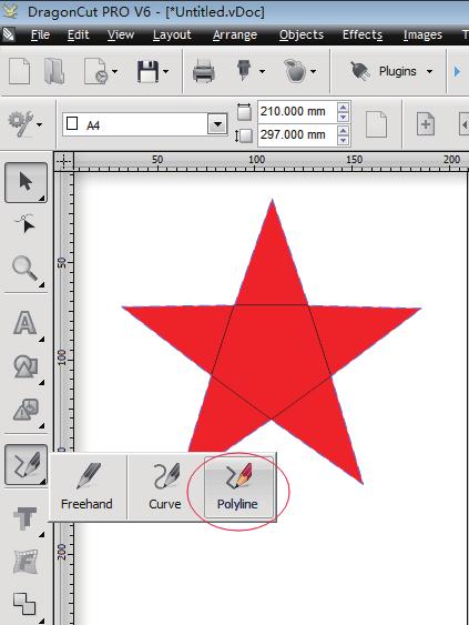
23 4.3 How to use DragonCut Blank file Import your file with cutting line and creasing line. Use your cutting line and creasing line with different colors. Click send to cutter. Select the color of the cutting line and creasing line. cut now
24 ARMS file Import your label file. Click create cut contour make outline for label. Through the hand-printed, making the creasing line. Select the cutting line, press the button use left mouse press the button use left mouse. Select creasing line, press the button use right mouse press the button use right mouse. Click contour cut wizard add marks for label Printer PDF and re-print(if you want printer it directly) than add cut job Click start the flatbed will be working, (if USB connection is ok, and the material is placed good)


25
26 CHAPTER 5 Fault and Maintenance 5. Scan Problem 5.2 Cutting Effect Problem 5.5 Error Messages
27 5. Scan Problem Phenomenon Scan Failed Cause Solution The sensor cannt scan first mark or secnd read failed. Check the print size, print size must the same size as the original file Sensor not bright First check the cable, if the line not problem so need to replace the sensor Sensor brightness problem The sensor is normal, the size is normal, but can not sweep point Normal size, sensor is normal, high normal, still can not scan First check the cable, if the line not problem so need to replace the sensor Please check the height of the inductor, usually the height of the sensor is 2.5mm distance from the paper material.maybe sensor canot scan the material.now please try use the material to test for corrected offset 2.The medium is not flat.
28 5.2Cutting effect problem Phenomenon Cause The starting and end points do not match. Solution.check your data 2.The offset is too low 3.The medium is too flimsy. 4.Knife holder rotation insensitive Adjust the OFFSET value. The cut corners are rounded If it is too low, the corners become rounded. or too pointed. If it is too high, the corners are too pointed. The Cutting Results are Unsatisfactory The cut line starts out crooked..knife holder rotation insensitive 2.The force is too low 3.Replace the cutter blade with a new one 4.Grease the cutter blade and holder. The blade skips and does not completely cut lines.lower the SPEED setting. 2.Adjust the blade length. The specified length is not plotted or cut. (slight distance error) Specify the appropriate distance correction value. Cutting deviation from normal cut line Corrected offset value again
29 Phenomenon Cause Solution Some parts of the medium.set the effective cutting area to a larger area. cannot be cut. 2.Reduce the size of the data. The Cutting Results are Unsatisfactory The medium is discolored wherethe cutter blade has passed. The cut medium cannot be picked up using a transfer sheet. 5.3 Error Messages Error:OVER SIZE PLEASE RESET. Solution:Check your data Check your starting point position Adjust the blade length and the cutting FORCE setting. Reduce the blade length. Lower the cutting FORCE.
30 6 CHAPTER Performance Parameter SG-FCA3+ SG-FC4560P SG-FC6090 Max Force 50g(3g/step) Max Speed 600mm/s Max Cutting Depth 0.60mm Max Cutting Weight (Paper) 450g Machincial Resolution 0.0 Number of tools 2 Programmable Resolution HPGL 0.025mm Contorl System Servo Motor Interface USB Cable Software DragonCut Working Enviroment to 20 VAC/200 to 240 VAC, 50/60 Hz Power Supply Marking film (vinyl, fluorescent, reflective) Paper up to 0.5 mm thick (pattern paper, oilboard)*4 Compressed foam sheets up to 0.8 mm thick *5 Sandblast rubber sheets up to.0 mm thick *5 F and G flute Sheets for creating clear packages High-intensity reflective film*6 Cutting Media Power SG-FC W/50HZ Media hold-down method 925W/50HZ Vacuum suction (silence device) Vacuum suction Machine Size 760*768*299mm 875*885*295mm Packing Size *886*452mm 23*00*437mm 20*290*450mm 573*406*586mm GW/NW 68kg/35.6kg 83kg/50kg 75*33*000.5mm 283*268*97mm 00kg/70kg 80kg/40kg
31 Thank you for your reference, if you have any questions, please contact the local dealer. Thank you again! From saga FLATBED CUTTER
Operation manual. Thanks very much for purchasing this. cutter/plotter. To ensure you make best use of your machine,
 Operation manual Thanks very much for purchasing this cutter/plotter. To ensure you make best use of your machine, please read this manual carefully and thorughly beforhand. IMMEDIATELY power off the machine
Operation Manual. Chap. 1 Attention. Please read the attention carefully before operating the machine.
 Chap. 1 Attention Please read the attention carefully before operating the machine. 1. No magnetic devices should be placed in the vicinity of the plotter, specifically the carriage. 2. Prevent from dropping
Vinyl Cutter Instruction Manual
 Vinyl Cutter Instruction Manual 1 Product Inventory Inventory Here is a list of items you will receive with your vinyl cutter: Product components (Fig.1-4): 1x Cutter head unit complete with motor, plastic
USER MANUAL Uninet LF-600 Digital die cutter for sheet labels
 USER MANUAL Uninet LF-600 Digital die cutter for sheet labels this product is certified: imark DIGITAL CUTTING SOFTWARE This software has been designed to effectively cut sheet labels. There are also functions
OPERATING MANUAL. for flatbed vinyl cutters. Secabo FC50 and FC100
 OPERATING MANUAL for flatbed vinyl cutters Secabo FC50 and FC100 Congratulations on the purchase of your Secabo flatbed vinyl cutter! Please read this operating manual carefully to ensure a smooth production
User Manual for: SAGA-720I, SAGA-1350I SAGA-720II, SAGA-1350II
 User Manual for: SAGA-720I, SAGA-1350I SAGA-720II, SAGA-1350II Specialized in developing, designing and manufacturing kinds of vinyl cutter Congratulations on purchasing cutting plotter! NOTICE We reserve
RoboPro CE CRP: Hardware
 RoboPro CE5000-40-CRP : CMi User Manual 2010 Last Update : March 25, 2011 EPFL - STI - CMI RoboPro CE5000-40-CRP: Hardware The RoboPro CE5000-40-CRP is a cutting plotter. It is a system which achieves
COLE. Cutting Plotter CL365/720/870/1100/1350. Instruction Manual
 COLE Cutting Plotter CL365/720/870/1100/1350 Instruction Manual Contents I. General Safety Rules 1 II. Specifications 2 III. Plotter Components Diagram 3 IV. Assembly Diagram of Plotter Stand 4 V. Loading
Quick Start Guide. Contents
 1 Quick Start Guide Contents Powering on the Machine Login/Password Entry Jaw Set Up High Security Cut by Code High Security Jaw Set Up Edge Cut Cut by Code Edge Cut Cut by Decode Cutter Replacement Tracer
RR Series TM USER GUIDE. For Vinyl Express R Series Cutters
 RR Series TM USER GUIDE For Vinyl Express R Series Cutters Thank you for choosing an R Series cutter from SignWarehouse, Inc. Before using your cutter, we suggest you read this guide. It will guide you
Manual. Operation. Special Declaration. was wrong.
 Thanks very much for purchasing cutting plotter. For ensuring you to make best use of the machine, please read this manual carefully and thoroughly before you starting to use the machine. Please turn off
Content. Before You Start. Assemble the 3D Printer. Use the 3D Printer. Load Filament Level the Heated Bed Start Printing Support
 Quick Start Guide Content A Before You Start B Assemble the 3D Printer C Use the 3D Printer Load Filament Level the Heated Bed Start Printing Support 2 Before You Start Get the Screwdriver Ready The screwdriver
CC200 USER S MANUAL. MANUAL NO. CC200m-UM-151 CH 1. PRIOR TO USE INDEX CH 3. CRAFT ROBO CONTROLLER PREFACE. Appendix A. Standard Specifications
 CC200 USER S MANUAL MANUAL NO. CC200m-UM-151 PREFACE Thank you for purchasing the Craft ROBO CC200. Based on cutting-plotter technology developed by Graphtec over many years, CC200 provides outstanding
SECTION 9: PARTS. Table Breakdown REF PART # DESCRIPTION REF PART # DESCRIPTION
 SECTION 9: PARTS Table Breakdown 1 2 3 4 5 6 7 8 9 10 11 12 13 14 15 16 17 18 19 20 21 22 23 24 23 25 17 26 27 8 1 P0675001 CAP SCREW M8-1.25 X 30 15 P0675015 SUPPORT BLOCK 2 P0675002 TABLE SUPPORT BLOCK
TM Quick Start Guide
 TM Quick Start Guide Contacting Pazzles By Phone In the US: 866-729-9537 International: +1-208-922-3558 Phone Hours: Mon - Fri, 9am - 5pm Mountain Time By Email Customer Service: Technical Support: Sales:
ABM International, Inc.
 ABM International, Inc. Lightning Stitch required 1 1.0: Parts List head and motor assembly (Qty. 1) Reel stand (Qty. 1) Needle bar frame clamp (Qty. 1) Motor drive (Qty. 1) 2 Cable harness with bracket
Cutting Plotter. CE6000 Series. Specifications CE CE AMO. Item CE CE bit CPU Grit rolling type, digital servo drive
 Cutting Plotter. CE6000 Series Specifications Ite CE6000-40 CE6000-60 CPU 32-bit CPU Configuration Grit rolling type, digital servo drive CE6000-120 CE6000-120- AMO Max. cutting area 375 x 50 *1 603 x
Software manual. F-Mark software manual_e02
 Software manual F-Mark software manual_e02 CONTENTS imark software panel layout...1 Graphics file design...2 Layers for printing...3 Layers for Cutting...4 Save file for Cutting...5 Crop Marks position
С 800 CASSIDA C 800 HIGH SPEED COIN COUNTER
 С 800 CASSIDA C 800 HIGH SPEED COIN COUNTER This manual contains important information on safety measures and operational features. Please read it carefully before operating your coin counter, and keep
The CNC Tangent Die Cutter
 The CNC Tangent Die Cutter Instruction Book If you have any questions, please see a DM Staff Member Digital Media Tutorial Written By John Eberhart Using the CNC Tangent Die Cutter The CNC Tangent Die
Start Here. Installing your Microtek ScanMaker 9800XL Plus PC:
 Start Here Installing your Microtek ScanMaker 98XL Plus Step : Unpack Contents. Optional package items depend on the scanner configuration that you purchased. Unpack your scanner package and check for
SCITEX Dual Roll Kit. User s guide
 SCITEX Dual Roll Kit User s guide 2011 Hewlett-Packard Development Company, L.P. First edition Legal notices The information contained herein is subject to change without notice. The only warranties for
OPERATING INSTRUCTIONS. for the labelcutter and labelfinisher. Secabo LC30
 OPERATING INSTRUCTIONS for the labelcutter and labelfinisher Secabo LC30 Congratulations on the purchase of your Secabo labelcutter! Please carefully read the operating manual to easily integrate your
Export Service Bulletin
 Applies To: Models With Sidewinder-Type Keys ALL Export Service Bulletin 01-077 October 2002 Cutting Sidewinder-Type Keys With the MATRIX H Key Cutting Machine (Supersedes 01-077, dated December 2001)
Jarvis standing desk. Assembly instructions. For assembly assistance, visit fully.com/howtojarvis or call or
 Jarvis standing desk Assembly instructions For assembly assistance, visit fully.com/howtojarvis or call 888-508-3725 or email support@fully.com Thank you for choosing a Jarvis desk from Fully. Cautions
END MILL RE-SHARPENER EMG-413
 END MILL RE-SHARPENER EMG-413 OPERATING INSTRUCTIONS -TABLE OF CONTENTS- A.SAFETY INSTRUCTIONS -------- 1 B.NAMES OF COMPONENTS ----- 2 C.OPERATIONS ------------------------ 3 D.REPLACING THE WHEEL --------
OPERATION MANUAL MIMAKI ENGINEERING CO., LTD.
 OPERATION MANUAL MIMAKI ENGINEERING CO., LTD. http://www.mimaki.co.jp/ E-mail:traiding@mimaki.co.jp D200674 About FineCut for CorelDRAW Thank you very much for purchasing a product of Mimaki. FineCut,
FLT-02 User Manual. Contents. Page 2 Page 3 Page 4 Page 5-7 Page 8
 FLT-0 User Manual Contents Caution/Liability Technical Specifications Parts Assembly Instructions Operational/Reset Procedure, Troubleshooting Dimensions Page Page 3 Page 4 Page 5-7 Page 8 Page 9 Caution
RYOBI. 10 in. (254 mm) TABLE SAW MODEL NO. BTS15 REPAIR SHEET
 TABLE SAW MODEL NO. BTS15 REPAIR SHEET") RYOBI 0 in. ( mm) TABLE SAW MODEL NO. BTS REPAIR SHEET FIGURE A 0 0 0 0 The model number will be found on a plate attached to the motor housing. Always mention the model number in all correspondence regarding
RYOBI 0 in. ( mm) TABLE SAW MODEL NO. BTS REPAIR SHEET FIGURE A 0 0 0 0 The model number will be found on a plate attached to the motor housing. Always mention the model number in all correspondence regarding
QUANTUM Qflash T2 / X2 OPERATING INSTRUCTIONS
 QUANTUM Qflash T2 / X2 OPERATING INSTRUCTIONS 1.0 DESIGNATIONS T2 AND X2 1. Removable Reflector, two positions Normal and Wide angle. 2. Flash-tube 2A. Modeling Lamp (for Model X2 only) 3. Bounce Head,
ABM International, Inc. Navigator Assembly Manual
 ABM International, Inc. 1 1.0: Parts List Tablet (Qty. 1) Tablet mount (Qty. 1) NOTE: Mount may appear and operate different then image below Control Box (Qty. 1) Motor Power Supply (Qty. 1) 2 X-axis motor
PCB Prototyping Machine FP-7A / FP-21A. User's Guide MITS Electronics
 PCB Prototyping Machine FP-7A / FP-21A User's Guide MITS Electronics Revision 091210 Bug Fixed: require Acrobat Japanese font pack CONTENTS: Notes of Caution Connect Boardmaker to PC Install Software(mdp)
SENA INSTRUCTION MANUAL
 SENA INSTRUCTION MANUAL CONTENTS: 1 PRESENTATION AND GENERAL ASPECTS... 2 1.1 GENERAL POINTS... 2 1.2 TRANSPORT AND PACKING... 2 1.3 IDENTIFICATION LABEL... 2 2 CHARACTERISTICS OF THE MACHINE... 3 2.1
RISK OF SHOCK: DO NOT WIPE DOWN ANY ELECTRICAL COMPONENTS. ALWAYS KEEP AWAY FROM ALL AREAS WHERE ELECTRONIC COMPONENTS ARE INSTALLED.
 Maintenance General Cleaning Waste material from the printing process can accumulate inside the printer. Using a slightly damp, lint-free cloth, wipe the interior of the CubePro including the print plate,
Problem/Procedure Description. Requirements. Problem/Procedure Solution. How-To Document. Updated on: 11/13/2008 By:Christopher Ware
 Problem/Procedure Description Performing maintenance on 95s, 95sII and H100 Requirements Ball Bearing Grease (LPKF P/N 106976) Tri-Flow Teflon lubricant aerosol. 3-in-1 Multi-purpose Oil Electronic Component
Installation Guide. English. English
 Installation Guide Safety Instructions For your safety, read all the instructions in this guide before using the setting plate. Incorrect handling that ignores instructions in this guide could damage the
so you want to get to know Onsrud... Onsrud1 : machine set up
 so you want to get to know Onsrud... Onsrud1 : machine set up What does CNC mean? CNC: Computer Numerical Control The router is controlled by a computer, that tells the router where to go through a series
Print Finishing Equipments
 Print Finishing Equipments Welcome to The New Generation of Print Finishing Possibilities Venture Inovations, a prominent business house based in Sankarapuram, Villupuram, Tamilnadu, India. Venture Inovations
2020 DRAWBOT INSTALLATION AND USE. Robert Ashford Henry Arnold 4-H OABB
 2020 DRAWBOT INSTALLATION AND USE Robert Ashford Henry Arnold 4-H OABB 2020 DrawBot Software If you are viewing this document, you probably just finished assembling your 2020 DrawBot. In order to use your
HydroFORM Phased Array Corrosion Mapping System Part 2 Mechanical Setup
 HydroFORM Phased Array Corrosion Mapping System Part 2 Mechanical Setup HydroFORM Corrosion Mapping System Mechanical Setup The HydroFORM Phased Array System is designed to perform corrosion mapping in
Content. 1. Unpacking Component Description Hardware Installation Software Application...5. (1) Software Installation.
 Software Installation.") WWW.BIQU.EQUIPMENT Content 1. Unpacking 1 2. Component Description.2 3. Hardware Installation...3 4. Software Application...5 (1) Software Installation.5 (2) Slicing Operation...7 Appendix...... 8 5. Automatic
WWW.BIQU.EQUIPMENT Content 1. Unpacking 1 2. Component Description.2 3. Hardware Installation...3 4. Software Application...5 (1) Software Installation.5 (2) Slicing Operation...7 Appendix...... 8 5. Automatic
PC: A. Place the Microtek CD-ROM into the CD- ROM drive. B. Follow the on-screen instructions to install the driver and software.
 Start Here Installing your Microtek ScanMaker s450/s350 Step 1: Unpack Contents Unpack your scanner package and check for major components. 1 1. Scanner with built-in transparency adapter 2. Software CD
fi-6130 / fi-6230 Cleaning and Maintenance
 fi-6130 / fi-6230 Cleaning and Maintenance fi-6130 / fi-6230 Cleaning and Maintenance fi-6130 / fi-6230 Image Scanner Operator's Guide Chapter 4 DAILY CARE This chapter describes how to clean the scanner.
Installation Guide. English. English
 Installation Guide Safety Instructions For your safety, read all the instructions in this guide before using the setting plate. Incorrect handling that ignores instructions in this guide could damage the
Interactive Monitor Arm
 Interactive Monitor Arm Tools Required -5mm Allen wrench -Phillips screwdriver -Plastic mallet There are two ways to attach a Monitor Arm to a Full Frame; with a Beam, or with a Post Mount. Both methods
SFP-550. Operating Manual MATSUHIDAI, MATSUDO-CITY, CHIBA JAPAN TEL: FAX:
 SFP-550 Operating Manual 296-1 MATSUHIDAI, MATSUDO-CITY, CHIBA 270-2214 JAPAN TEL: +81-47-388-6111 FAX: +81-47-388-4477 Safety Precautions To ensure safe operation and maximize product service life, observe
 GENERAL OPERATIONAL PRECAUTIONS WARNING! When using electric tools, basic safety precautions should always be followed to reduce the risk of fire, electric shock and personal injury, including the following.
2012 Monitored Rehab Systems E1201 Manual Kneelax. Installation and user manual
 2012 Monitored Rehab Systems E1201 Manual Kneelax Installation and user manual Table of contents CHAPTER 1 Installation Manual... 3 1.1 Install Kneelax USB driver... 3 1.2 Detect COM-port... 6 1.3 Software
Z-Truck Up-and-Down Motion. Y-Truck Side-to-Side Motion. Head. Squaring Plate. Sliding Plate FIGURE 1: THE CARVEWRIGHT MACHINE
 Setup and use of CarveWright CO2 Powered Dragster Jig The CO 2 powered Dragster Jig will arrive from the factory fully assembled, calibrated, and squared. In order to get the best results, your CarveWright
PT 335SCC Multi Operator Manual
 PT 335SCC Multi Operator Manual 755 Griffith Court, Burlington, Ontario, Canada L7L 5R9 Tel:+(905) 633-7663 Fax:+(905) 637-4419 www.graphicwhizard.com 1 TABLE OF CONTENTS Important Information General
Volvo 240/260 New Face Overlay Installation Models By Dave Barton
 Volvo 240/260 New Face Overlay Installation 1975-80 Models By Dave Barton These custom faces are the product of years of research and experimentation. They are printed with a special printer using waterproof
Band-Master ATS Nano Pneumatic Banding Tool Operating Instructions
 Band-Master ATS 601-118 Nano Pneumatic Banding Tool CONTENTS 601-118 Overview... 3 Safety.... 5 Initial Tool Set-up... 5 Regulator assembly mounting... 5 Attach tool head to regulator.... 6 Operating instructions...
Installation and Operating Instructions Desk top Laser
 www.katanatrading.com Installation and Operating Instructions Desk top Laser This manual covers the following: A. Unpacking and setup of the engraver B. Installation of Newly Seal software C. Basic operation
Scanner Parts. Scanner Specifications. General. Mechanical. Epson Perfection V200 Photo. P Power/ ] Start button Status light. { Copy button.
![Scanner Parts. Scanner Specifications. General. Mechanical. Epson Perfection V200 Photo. P Power/ ] Start button Status light. { Copy button.](/thumbs/73/68379766.jpg "Scanner Parts. Scanner Specifications. General. Mechanical. Epson Perfection V200 Photo. P Power/ ] Start button Status light. { Copy button.") Scanner Parts { Copy button Scan to E-mail button a b P Power/ ] Start button Status light c e d a Scan to PDF button Film holder Scanner Specifications General Scanner type Flatbed color Photoelectric
Scanner Parts { Copy button Scan to E-mail button a b P Power/ ] Start button Status light c e d a Scan to PDF button Film holder Scanner Specifications General Scanner type Flatbed color Photoelectric
Label Studio Quick Start Guide
 Label Studio Quick Start Guide Overview The goal of the LabelStudio program is to help you layout and manage bulk jobs containing a mix of different logos, that all require a specified quanity. LabelStudio
The Mini Pinni Quilting Frame
 The Mini Pinni Quilting Frame Copyright September 2007 Jim M. Bagley, GraceWood, Inc (Reproduction Prohibited) Print Date 10-16-07 1 The Mini Pinni Quilting Frame By The Grace Company Part List Parts List
Start Here. Unpack Contents. Install Software. Installing your Microtek Bio-5000 Plus
 Start Here Installing your Microtek Bio-5000 Plus Unpack Contents Unpack your scanner package and check for major components. 1. Bio-5000 Plus scanner 2. Hi-Speed USB cable LEAK-FREE GLASS HOLDER This
Ladybird Project - Vacuum Mould
 - Vacuum Mould Prerequisite Mould drawn and saved as an STL file in SolidWorks Focus of the Lesson On completion of this exercise you will have: Opened an STL file Set Machining Constraints Set up Tools
WELCOME WHAT S IN THE BOX
 WELCOME Congratulations on purchasing your Visioneer PaperPort flatbed scanner. With your scanner, you can quickly scan paper documents and color photos to place their electronic images on your computer.
Instruction manual SUN-PM100L. SUN-PM100L Polishing Machine English
 Instruction manual SUN-PM100L SUN-PM100L Polishing Machine English Table: SUN-UM-TL-PM001 Version: A/0 Fiber Optic Solutions Provider Ⅰ Safety Precautions To ensure safe operation and maximize product
(Assembling Guide supplied by imakr ) with the support of MyMiniFactory.com
 with the support of MyMiniFactory.com") (Assembling Guide supplied by imakr ) with the support of MyMiniFactory.com Summary Congratulations on beginning on your journey into 3D printing with the STARTT 3D printer. In this guide, you will have
(Assembling Guide supplied by imakr ) with the support of MyMiniFactory.com Summary Congratulations on beginning on your journey into 3D printing with the STARTT 3D printer. In this guide, you will have
METRICFATS.COM Thank you for purchasing your new Stealth Rear Turn Signals for your Yamaha Raider.
 METRICFATS.COM Thank you for purchasing your new Stealth Rear Turn Signals for your Yamaha Raider. The instructional sheets that follow are thoroughly detailed and should be studied BEFORE picking up a
SFP-550. Operating Manual MATSUHIDAI, MATSUDO-CITY, CHIBA JAPAN TEL: FAX:
 SFP-550 Operating Manual 296-1 MATSUHIDAI, MATSUDO-CITY, CHIBA 270-2214 JAPAN TEL: +81-47-388-6111 FAX: +81-47-388-4477 Safety Precautions To ensure safe operation and maximize product service life, observe
W-Pressing Assembly. the top W roller thus creating a uniform and constant pressure between and throughout both top and lower W rollers.
 PRODUCT: NUR Fresco HiQ 3200 ISSUE DATE: 10-Sep-02 SOFTWARE AFFECTED: YES NO TYPE OF CHANGE: MANDATORY COST PRODUCTION MAINTENANCE PROJECT MANAGER: SIGNATURE/DATE PART/ASSEMBLY: FCO KIT P/N: 10-0803 W-Pressing
OPERATION AND MAINTENANCE HANDBOOK D407270XA
 OPERATION AND MAINTENANCE HANDBOOK D407270XA vers. 1.0 Thank you for choosing one of Silca s high quality key cutting machines. This machine has been designed, tested and produced in our factory using
767, 777, DC-10, L-1011, MD-11 Tow Bar Equipment Manual
 514 MECKLEM LANE, ELLWOOD CITY, PENNSYLVANIA 16117 www.hallindustries.com E-mail: service@hallindustries.com 767, 777, DC-10, L-1011, MD-11 Tow Bar Equipment Manual Use This Manual for 1. Operating Procedures
UPLIFT Height Adjustable Standing Desk 3-Leg (T-Frame) DIRECTIONS FOR ASSEMBLY AND USE
 DIRECTIONS FOR ASSEMBLY AND USE") UPLIFT Height Adjustable Standing Desk 3-Leg (T-Frame) DIRECTIONS FOR ASSEMBLY AND USE CAUTION MAKE SURE NO OBSTACLES ARE IN THE DESK S PATH AND ALL CORDS ARE OF APPROPRIATE LENGTH FOR DESK TRAVEL. FAILURE
UPLIFT Height Adjustable Standing Desk 3-Leg (T-Frame) DIRECTIONS FOR ASSEMBLY AND USE CAUTION MAKE SURE NO OBSTACLES ARE IN THE DESK S PATH AND ALL CORDS ARE OF APPROPRIATE LENGTH FOR DESK TRAVEL. FAILURE
UltraFeed Feeder Operator s Manual
 UltraFeed Feeder Operator s Manual Version 1.1 Table of Contents Topic Page Safety Statement and Recommendations 3 General Operation and Set-Up 5 Control Panel Operation 6 Set Up and Operation 7 Set Up
Progeny Integrated Mobile Unit Unpacking/Assembly Guide
 Summary: The following instruction will guide you through the unpacking and installation of the Progeny Mobile Unit. Any question or concerns or suggestions should be directed to Progeny Technical Support
JD-12. Instruction & Parts Manual
 JD-12 Instruction & Parts Manual Framon Manufacturing Company, Inc. 909 W Washington Avenue Alpena, MI 49707 Phone: 989-354-5623 Fax: 989-354-4238 E-mail: support@framon.com Website: www.framon.com The
Table of Contents CONTENTS
 Table of Contents CONTENTS Introduction... 2 Contact TKI... 2 Printer Features & Definitions... 3 Software Parameter Setup... 8 Setting Up A Printer Profile in Cura... 8 Printing Settings... 13 Printing
General Help. Last revised: Winter When I try to print something on the computer, it appears to work, but nothing comes out of the printer.
 General Help Last revised: Winter 2015 Problem Solution When I try to print something on the computer, it appears to work, but nothing comes out of the printer. See the next item. When I try to print something
Model W1837 (For Machines Mfd. Since 8/18) PARTS. Main PARTS -83-
 PARTS. Main PARTS -83-") -83- Main 29 30 31 34 35 36 37 38 39 40 41 42 43 44 45 46 47 48 49 50 51 52 53 54 55 56 57 58 61 62 63 64 65 66 67 68 69 70 71 72 73 74 75 113 96 90 91 92 93 95 96 97 98 100 101 102 103 104 105 106 109
-83- Main 29 30 31 34 35 36 37 38 39 40 41 42 43 44 45 46 47 48 49 50 51 52 53 54 55 56 57 58 61 62 63 64 65 66 67 68 69 70 71 72 73 74 75 113 96 90 91 92 93 95 96 97 98 100 101 102 103 104 105 106 109
Inde-Pendants Family. 32L Ring Plaster Trim, Grid and Drywall Ceiling Types. Document No Installation instructions for 32L-Rxx-P
 Inde-Pendants Family 32L Ring Plaster Trim, Grid and Drywall Ceiling Types Installation instructions for 32L-Rxx-P Document No. Supplied by Litecontrol 32L Inde-Pendants: Ring (Plaster Trim, Grid and Drywall
UNIVERSITY OF WATERLOO Physics 360/460 Experiment #2 ATOMIC FORCE MICROSCOPY
 UNIVERSITY OF WATERLOO Physics 360/460 Experiment #2 ATOMIC FORCE MICROSCOPY References: http://virlab.virginia.edu/vl/home.htm (University of Virginia virtual lab. Click on the AFM link) An atomic force
UNDERPINNERS CS 88 & CS 89 FOOT-OPERATED PNEUMATIC. Technical and User Manual. Version 1 au 12 / 01. Cassese / Communication
 UNDERPINNERS CS 88 & CS 89 FOOT-OPERATED PNEUMATIC Technical and User Manual Version 1 au 12 / 01 Cassese / Communication CS88 / CS 89 - Technical and User Manual CONTENTS PAGE N INTRODUCTION ACCESSORIES
User Manual. Digital Compound Binocular LED Microscope. MicroscopeNet.com
 User Manual Digital Compound Binocular LED Microscope Model MD82ES10 MicroscopeNet.com Table of Contents i. Caution... 1 ii. Care and Maintenance... 2 1. Components Illustration... 3 2. Installation...
JEWEL, SAPPHIRE, STAR and NOVA Turntables
 sotaturntables@kwom.com - www.sotaturntables.com JEWEL, SAPPHIRE, STAR and NOVA Turntables PLEASE READ THE INSTRUCTIONS COMPLETELY BEFORE BEGINNING SET UP AND OPERATION! UNPACKING The SOTA turntable comes
UPLIFT 2-Leg Height Adjustable Standing Desk
 UPLIFT -Leg Height Adjustable Standing Desk Also watch our assembly video http://bit.ly/9ywwh DIRECTIONS FOR ASSEMBLY AND USE TABLE OF CONTENTS PAGE Safety and Warnings Usage Parts List Assembly Instructions
52 5 N. Instructions & Parts List. From the library of: Superior Sewing Machine & Supply LLC
 52 5 N Instructions & Parts List z L.f) N L!) _J w 0 0 ~ INSTRUCTION BOOK FOR MODEL 5 2 5 N 1. Starting. Attach the operation handle (No.54) to the machine and after confirming that the switch (No.56)
Assembly Instructions: Kit #5
 Assembly Instructions: Kit #5 1. Insert the T-pin into one of the caps. 2. Insert the rotor core into the same cap as shown below. Apply some pressure to push the rotor core approximately 1/2" (10-12 mm)
MOTOR REPLACEMENT : STEP BY STEP.
 (D) REPLACEMENT : STEP BY STEP. (V) Adjustment screw (Allen key 3/16 ) (E) (U) (I) Tightening screw (Allen key 5/32 ) Blocking screw (H) (Allen key 5/32 ) (G) (Y) (T) (ZZ) (Z) (K) (X) (L) (S) (W) (R) (Q)
Installation Operation Care
 Installation Operation Care Designer Roller and Designer Screen Shades Standard and Cassette Cordless Lifting System CONTENTS Getting Started: Product Views... 1 Tools and Fasteners Needed... 3 Installation
SUNRISE UPGRADE KIT for LAI "SkillTester"
 SUNRISE UPGRADE KIT for LAI "SkillTester" This upgrade is designed to suit the early model LAI Skill Tester machines. These machines have a Move Forward and a Move Right button, and no sound effects. The
Instructions for Tecnai a brief start up manual
 Instructions for Tecnai a brief start up manual Version 3.0, 8.12.2015 Manual of Tecnai 12 transmission electron microscope located at Aalto University's Nanomicroscopy Center. More information of Nanomicroscopy
FX1200 Digital Label Finishing System Frequently Asked Questions Primera Technology, Inc.
 FX1200 Digital Label Finishing System Frequently Asked Questions Primera Technology, Inc. (As of February 24, 2010) 1. What is the FX1200? FX1200 is an all-in-one, digitally-controlled label finishing
DXXX Series Servo Programming...9 Introduction...9 Connections HSB-9XXX Series Servo Programming...19 Introduction...19 Connections...
 DPC-11 Operation Manual Table of Contents Section 1 Introduction...2 Section 2 Installation...4 Software Installation...4 Driver Installastion...7 Section 3 Operation...9 D Series Servo Programming...9
ET-413 2MP USB PEN MICROSCOPE
 ET-413 2MP USB PEN MICROSCOPE USER S MANUAL INTRODUCTION FUNCTIONS AND APPLICATIONS The ET-413 2 Mega-Pixel USB PEN MICROSCOPE is a new electronic product for micro observations. It is a tubular imaging
HAPPY HCS Voyager: Level-1 Maintenance & Repair Intermediate-level repair / maintenance procedures
 TEXMAC Inc. HAPPY HCS Voyager Introduction Training page 1 HAPPY HCS Voyager: Level-1 Maintenance & Repair Intermediate-level repair / maintenance procedures Table of Contents Oiling/Cleaning Page 2 Removing
MODEL T " SPIRAL CUTTERHEAD INSTALLATION INSTRUCTIONS
 MODEL T27449 8" SPIRAL CUTTERHEAD INSTALLATION INSTRUCTIONS The Model T27449 indexable insert spiral cutterhead is designed to replace the straightknife cutterhead on the Grizzly jointer Model G0490W/G0490XW
BIGBOT ASSEMBLY INSTRUCTIONS. 1/18/2017 V0.5
 BIGBOT ASSEMBLY INSTRUCTIONS www.bigbot-3d.com 1/18/2017 V0.5 FOREWORD: PLEASE TAKE CARE WHEN HANDLING THE GANTRY. THE ASSEMBLY SHOULD BE HANDLED ONLY BY THE ALUMINUM FRAME, AND AVOID TOUCHING OR LIFTING
Latex Knowledge Center. Cookbook - HP Latex Print and Cut Solution
 Latex Knowledge Center Cookbook - HP Latex Print and Cut Solution January 2018 Table of contents Table of contents... 2 Overview... 4 1.1 Who can benefit from reading this document?... 4 The HP Latex Print
Be sure any accessory used will fit with the soft upper doors before installing. Not all accessories will be compatible.
 Company Name: Spike Power Sports Vehicle Name: Polaris General 2P Product Description: Soft Upper Doors Part Number: 58-1600 Revision: R01 09/19/2018 Contents: 655 Elm Ridge Ave, Canal Fulton OH, 44614
Craft ROBO Pro2 (CE CRP)
") Craft ROBO Pro2 (CE3000-40-CRP) Supplementary User s Manual CE3000CRP-UM-551, 1st edition September 1, 2005 The following items have been added to the CE3000-40. Chapter 1 Chapter 2 PAUSE Menu List Folding
Craft ROBO Pro2 (CE3000-40-CRP) Supplementary User s Manual CE3000CRP-UM-551, 1st edition September 1, 2005 The following items have been added to the CE3000-40. Chapter 1 Chapter 2 PAUSE Menu List Folding
The Bowflex Revolution XP Home Gym Assembly Instructions. P/N: Rev ( /0 )
") P/N: 001-7057 Rev ( /0 ) The Bowflex Revolution XP Home Gym Assembly Instructions 2 Table of Contents Before You Start... 2 Tools You Will Need / Hardware Contents... 3 Box Contents... 6 Assembling Your
P/N: 001-7057 Rev ( /0 ) The Bowflex Revolution XP Home Gym Assembly Instructions 2 Table of Contents Before You Start... 2 Tools You Will Need / Hardware Contents... 3 Box Contents... 6 Assembling Your
Studuino Icon Programming Environment Guide
 Studuino Icon Programming Environment Guide Ver 0.9.6 4/17/2014 This manual introduces the Studuino Software environment. As the Studuino programming environment develops, these instructions may be edited
Cut-True 16M Manual Paper Cutter
 Cut-True 16M Manual Paper Cutter 2/2013 OPERATOR MANUAL FIRST EDITION TABLE OF CONTENTS TOPIC PAGE Specifications 1 Safety Guidelines 1 Assembly 2 Overview 3 Description of Equipment Parts 3-4 Operation
TROUBLE-SHOOTING: Error States
 TROUBLE-SHOOTING: Error States Please note, there is much commonality between the different models of LabelStation and therefore it is advisable to read the comments on other models if you cannot find
FBX1104P FBX1104 FBX1106P FBX1106
 FBX1104P FBX1104 FBX1106P FBX1106 Second edition : September 2004 No. 040037 INTRODUCTION Thank you for your purchasing Kansai Special's FBX Series. Read and study this instruction manual carefully before
Number Wheeler P/N Description Set Rex P/N Notes Base 1 J Support, Right 1 J Support, Left 1 J Nut (M8)
") 1 603500 Base 1 J001 2 603501 Support, Right 1 J002 3 603502 Support, Left 1 J003 4 600328 Nut (M8) 4 5 600130 Spring Washer (8mm) 4 6 600344 Roll Pin (M6x30) 4 7 600129 Socket Hd Cap Screw (M8x25) 4 8
1 603500 Base 1 J001 2 603501 Support, Right 1 J002 3 603502 Support, Left 1 J003 4 600328 Nut (M8) 4 5 600130 Spring Washer (8mm) 4 6 600344 Roll Pin (M6x30) 4 7 600129 Socket Hd Cap Screw (M8x25) 4 8