RS 34 / 36 Squeeze Roller assembly instructions
|
|
|
- Angelica McCoy
- 5 years ago
- Views:
Transcription


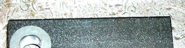
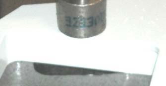
1 RS 34 / 36 Squeeze Roller assembly instructions Step 1. Assemble new bearing Make sure the tapper is going the correct direction Use fixture to press bearings into upper and lower rollers Press bearings into roller. Press bearing from the outside race only. (Press till bearing bottoms).


")


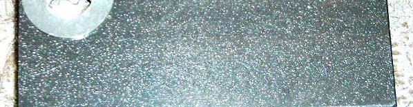
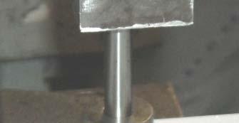
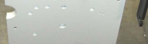
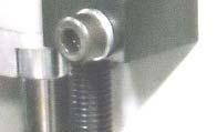
2 Use fixture to setup upper roller (upper roller needs spacer washer to align Rod for marking of rod and bearings) Place roller in fixture with belt drive side away from fixture then install rod into roller. Mark klocation of bearings then remove rod for dimpling.


 rotating during torque).")

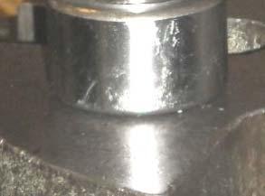
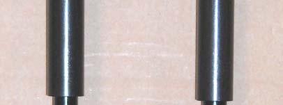
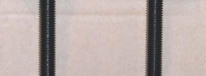
3 Tack weld dimple on both sides of the rod. Top rod Left side tack 3 1/8 from left end, Right side 2 3/4 from right end. tightening check shaft to roller spacing Bottom rod Left Lftid side tack k3 1/8 from lft left end, Right side 1 3/4 from right ihtend. with jig. (Dimples are to keep rod from (Make sure dimples from tack weld are in align to each other) rotating during torque). Dimples should be in height. Marked line on Jig is for upper roller Edge on Jig is for Lower roller


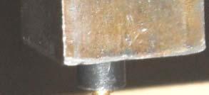
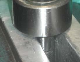
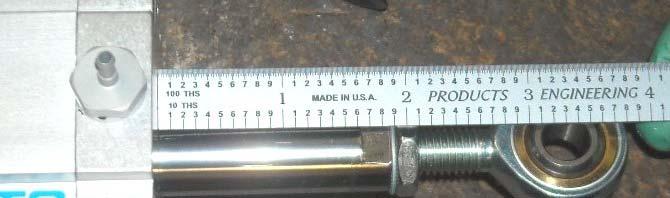
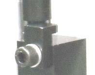
4 Check spacing of right side rod to roller 68mm. Place roller in fixture and clamp rod then torque to (min 43 Nm max 45 Nm) or 380 inch lbs to 400 inch lbs max.


 Rotate Rod")

 Place")


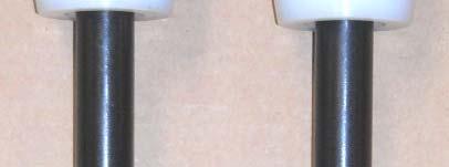
5 Loosen fixture and tap rod with soft face hammer then re torque bearings to previous torque settings. Check bearing linear play (min.2mm to max.65mm) / (min.005 max.015 inch) Rotate Rod for 5 revolutions to check bearings. (If tight check with Supervisor) Place roller on cart. Lower Roller assembly Repeat step 1. then Place on fixture. Flip indexing spacer for lower roller assembly.


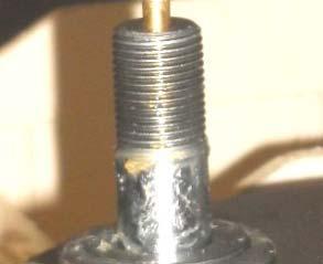
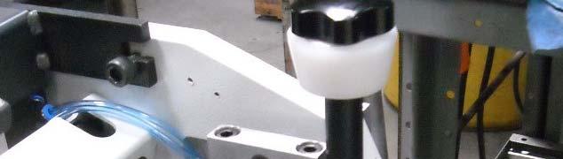
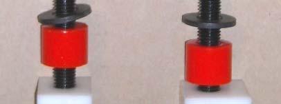
6 Install motor plate with ribbed washers and A6 20 socket head screws. Clean shaft and lube with rust inhibitor before installing pulley When installing pulley use a 10mm spacer then secure pulley with 4pc F8 10 set screws (2pc to tighten and 2pc to lock set screws).


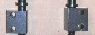
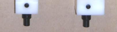
7 Install Bearing flush into pulley (Picture below is for Duel squeeze roller#36 331) Install Bearing flush into Brkt Install Bearing onto arbor M then press into arm Install pulley onto arm with A10 45 socket head lock washer and nut.


8 Spring # pc K120 washers 1.5 of 1 inch double side tape Press into Holder #29 133M Pressbushing # into (Be sure to press bushings correct configuration). Bracket # Bracket # Left Clamp # pc A M08 40 & L08 1pc A M08 30, L08 Rib Right Clamp # pc Bearing sleeve 2pc A M08 40 & L08 1pc A M08 30, L08 Rib Tap in plug provided with Bearing, Cam follower # Press zurt fitting half way, turn 90 degree and finish pressing.


 Rod")


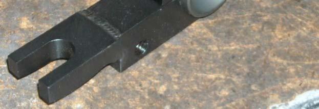
9 Lightly ygrease then press Dowel Pin K 220 from the outside of the plates using below fixture. Install plates in Jig Install cam followers. (Torque 45NM) Install Rod end with J M and LM10. Use jig to set throw of compression cylinder and snug Jam nut. Install 4mm clear blue air lines. Left cylinder top=40 bottom=36 Right cylinder top=32bottom=10 Check finished length 3.3 to center of Rod eye


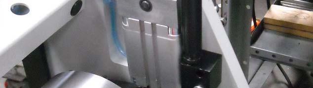
10 Install Lower roller assy with 2pc A10 30 socket screw and L10 lock washers. 48Nm 2. Install Tube MTG with Rod MTG using 4pc A8 40 screw with L210 Lock washers. 25Nm 3. Put drive belt around idler pulley and install idler with A6 35 screws with lock washers. 9Nm 1 Install right clamp onto Rod of the upper roller. Then install right bracket onto Cam follower bearing.


11 Hold ldroller in position and install lllftb Left bracket on left cam follower bearing. Torque brackets to 25Nm or 220 inch pounds (make sure rollers are perpendicular to each other).


12 Top View of left cylinder. Install 1pc K220 washer on dowel and 1 pc on Rod end then fasten with 4pc M08 45 with rib washers. 25Nm Right cylinder needs Spacer to go on rod end before fastening to right bracket then 4pc M08 45 with rib washers.


13 T connection for bottom cylinder connections. Inside view of left side. Run both lines inside tube. Bottom line goes to T on right side to tie the right bottom connection. Both top lines go to control box Lines are from top connections of cylinders that go to control box regulator (2) port


14 Install Delrin wedge between upper and lower rollers theninstalladjusters. adjusters. (remember to adjust them evenly). Left Right Light amount of black graphite grease Block Right side Top screw M08 50, LM08 Lower screw M08 45, LM08 Block Block spindle Block Block spindle Lftid Left side Top screw M08 45, LM08 Lower screw M08 45, LM08


15 Install Right block and left block with 2ps M06 25 and L06. 9Nm Put belt on Shaft and install with AM06 35 with L6 9Nm (wipe bear metal rollers with Jo Guard) Install spring and block then Belt idler with M Nm Route bltbf belt before mounting motor Put belt on pulley and fasten motor with 4pc spacers and AM with L08. 25Nm


16 Install Right and Left guards with AM05 12 and L05. Put idler assy with 1pc AM06 20 with L06 (snug tight)
Rotary Mower L47, M47, N47, RM44YR Parts Catalog
 R Ingersoll Rotary Mower L47, M47, N47, RM44YR Parts Catalog 8-2711 HOME TRACTORS ATTACHMENTS PAINT GENERAL INFO ALPHABETICAL Axle... 9 Bearings, Spindles... 11-13 Belts... 5-7 Blades... 11-13 Bracket,
25-200H. 12 Planer / Jointer. with Helical Cutterhead. Parts List.
 25-200H 12 Planer / Jointer with Helical Cutterhead 4001824 Parts List www.rikontools.com CABINET ASSEMBLY PARTS EXPLOSION & PARTS LIST KEY NO. DESCRIPTION KEY NO. DESCRIPTION 1 Pan Head Screw M6x12 P25-200H-1
Removing the Z-Axis lead screw
 Page 1 of 8 TITLE: Sabre Z-Axis Lead Screw Replacement Procedure Gerber FastFact #: 5048 Supplied by: Gerber Hardware Support Last Modified: June 14, 2007 Summary: Tools used: The following procedure explains
M2 Assembly. M2 Sub-Assemblies mm Belt Sub-Assembly mm Belt Sub-Assembly Spider Sub-Assembly... 4
 M2 Assembly Table of Contents M2 Sub-Assemblies... 3 630mm Belt Sub-Assembly... 3 702mm Belt Sub-Assembly... 3 Spider Sub-Assembly... 4 Idler Bolt Sub-Assembly... 8 Y Motor Sub-Assembly... 9 X Motor Sub-Assembly...
RYOBI 10 IN (254 MM) TABLE SAW MODEL NO. BT REPAIR SHEET
 TABLE SAW MODEL NO. BT REPAIR SHEET") RYOBI 0 IN (2 MM) TABLE SAW MODEL NO. BT00- REPAIR SHEET 2 RYOBI 0 in. (2 mm) TABLE SAW - MODEL NO. BT00- FOR MITER TABLE ASSEMBLY, REFER TO FIGURE B FOR BLADE GUARD ASSEMBLY, REFER TO FIGURE E FOR RIP
RYOBI 0 IN (2 MM) TABLE SAW MODEL NO. BT00- REPAIR SHEET 2 RYOBI 0 in. (2 mm) TABLE SAW - MODEL NO. BT00- FOR MITER TABLE ASSEMBLY, REFER TO FIGURE B FOR BLADE GUARD ASSEMBLY, REFER TO FIGURE E FOR RIP
HYDRAULIC CONTROL DETAILS PARTS LIST
 Always give model number, serial number and part number when ordering repair parts. HYDRAULIC CONTROL DETAILS PARTS LIST REF NO. PART NUMBER DESCRIPTION 1 101939 Hydraulic Tank 2 101940 Hydraulic Tank
RTI TECHNOLOGIES, INC.
 RTI TECHNOLOGIES, INC. BRC500 & BRC550 Arbor/Spindle Mechanism Adjustment & Service Technical Instructions The arbor/spindle mechanism of the BRC500/550 is designed to be robust for long life. Occasionally
INSTRUCTIONS AND PARTS LIST POWER HAMMER
 INSTRUCTIONS AND PARTS LIST POWER HAMMER DAKE (Division of JSJ) 724 Robbins Road Grand Haven, Michigan 49417 616.842.7110 Phone 800-937-3253 616.842.0859 Fax 800-846-3253 Web: www.dakecorp.com E-mail :
RYOBI 10 in. (254 mm) TABLE SAW MODEL NO. BT3100 REPAIR SHEET
 TABLE SAW MODEL NO. BT3100 REPAIR SHEET") RYOBI 0 in. (4 mm) TABLE SAW MODEL NO. BT00 REPAIR SHEET FOR MITER TABLE ASSEMBLY, REFER TO FIGURE B FOR BLADE GUARD ASSEMBLY, REFER TO FIGURE E FOR RIP FENCE ASSEMBLY, REFER TO FIGURE C FOR MOTOR ASSEMBLY,
RYOBI 0 in. (4 mm) TABLE SAW MODEL NO. BT00 REPAIR SHEET FOR MITER TABLE ASSEMBLY, REFER TO FIGURE B FOR BLADE GUARD ASSEMBLY, REFER TO FIGURE E FOR RIP FENCE ASSEMBLY, REFER TO FIGURE C FOR MOTOR ASSEMBLY,
This manual will aid in the assembly of the FireBall V90 and FireBall X90. The assembly of both machines will be identical, unless specified.
 This manual will aid in the assembly of the FireBall V90 and FireBall X90. The assembly of both machines will be identical, unless specified. Step #1 Lay all parts out to verify quantities. (2) 2 x 25-1/4
ABM International, Inc. Navigator Assembly Manual
 ABM International, Inc. 1 1.0: Parts List Tablet (Qty. 1) Tablet mount (Qty. 1) NOTE: Mount may appear and operate different then image below Control Box (Qty. 1) Motor Power Supply (Qty. 1) 2 X-axis motor
SUPER PRO GUN & SUPER PRO GUN II
 MAGNUM VENUS PRODUCTS Maintenance & Repair Manual Part No. M6707-1-1 Revision 04.14.01 Maintenance & Repair Corporate HQ & Mfg. Phone: (727) 573-2955 Fax: (727) 571-3636 Email: info@magind.com Web: www.magind.com
Parts Manual. Models 521 SSE (621502X37NA) 521 SSR (621503X37NA) &
 521 SSR (621503X37NA) &") Parts Manual Models 521 SSE (621502X37NA) 521 SSR (621503X37NA) 1740273 & 1740275 11.2006 Table Of Contents PRODUCT COMPONENTS PAGES Handle Group... 4 Engine Group... 6 Frame Group... 8 Auger Housing
Parts Manual Models 521 SSE (621502X37NA) 521 SSR (621503X37NA) 1740273 & 1740275 11.2006 Table Of Contents PRODUCT COMPONENTS PAGES Handle Group... 4 Engine Group... 6 Frame Group... 8 Auger Housing
 These are tricks or tips I use when working on a Mill These are intended for informational purposes only and not responsible for any injury or damage to the machine Removal of motor on a variable speed
RYOBI 10 in. TABLE SAW - MODEL NO. BT3000
 FOR MITER TABLE ASSEMBLY, REFER TO FIGURE 0 RYOBI 0 in. TABLE SAW - MODEL NO. BT000 FIGURE 5: 0 in. TABLE SAW FOR BLADE GUARD ASSEMBLY, REFER TO FIGURE FOR RIP FENCE ASSEMBLY, REFER TO FIGURE FOR MOTOR
w w w. h d o n l i n e s h o p. d e AUTOMATIC COMPRESSION RELEASE TOOL GENERAL INSTALLATION -J04654 REV Kit Number Models
 -J05 REV. 008-0- GENERAL Kit Number 98-08 Models AUTOMATIC COMPRESSION RELEASE TOOL For model fitment information, see the P&A Retail Catalog or the Parts and Accessories section of www.harley-davidson.com
MODEL NO.: MI PARTS BREAKDOWN
 MODEL NO.: MI-76350 PARTS BREAKDOWN MAGNUM DRILL PRESS ASSEMBLY INSTRUCTIONS MODEL MI-76350 Before you begin to assemble your drill press, review the parts breakdown and keep it ready for reference. Start
REPAIR INSTRUCTIONS. Cat. No Cat. No MILWAUKEE ELECTRIC TOOL CORPORATION. SDS Max Demolition Hammer. SDS Max Rotary Hammer
 Cat. No. 9-0 SDS Max Demolition Hammer Cat. No. -0 SDS Max Rotary Hammer MILWAUKEE ELECTRIC TOOL CORPORATION W. LISBON ROAD BROOKFIELD, WISCONSIN 00-0 8-9-0 d 000 8-9-0 d Special Tools Require Forcing
Deck Mount Installation with Bench
 Deck Mount Installation with Bench 1. Mark track with square. 2. Cut tracks with saw. 3. Drill ¼ hole (if needed.) 4. Countersink track. 5. Countersink all track 6. File all track ends. ends. 7. Lay out
Operating Instructions
 Operating Instructions Holding the material against the angle gauge slide it into the forming head. Be sure that the material remains against the gauge until work is finished. NOTE: This machine will handle
Parts Sheet. RSX096 High Force, Rod Style Actuator EXPLODED VIEW - RSX _00_RSX09. * Specify stroke length when ordering A/R = As Required
 RSX0 High Force, Rod Style Actuator Parts Sheet 00_00_RSX0 EXPLODED VIEW RSX0 0 0 0 PART NO or ITEM Config. Code DESCRIPTION QTY. 0 Leadscrew/Rollerscrew (Standard) Leadscrew/Rollerscrew (TRR Option) 0
Section D ACCELERATOR
 Section D ACCELERATOR 1D Index No. Part No. Description 1. 47-021476-001 Ball Accelerator Box 2. 11-051019-001 Hex Hd. Cap Screw (10 mm x 25 mm) 3. 11-052018-001 Flat Washer (10.5 mm x 21 mm x 2 mm) 4.
 488 PARTS LIST 1 3 SCREWS FOR NO. 2 2 FLYWHEEL CAP 3 FLYWHEEL 4 END NUT FOR NO. 10 5 BALL BEARING FOR NO. 3 (1 st ) 6 BALLBEARING FOR NO. 3 (2nd) 7A CLUTCH RACE KEY 7B CLUTCH RACE 7C CLUTCH SPRING 7D 7
TorqueMaster Replacement Spring
 TorqueMaster Replacement Spring Installation Instructions NOTE: Use these installation instructions in conjunction with the TorqueMaster Repair / Replacement Spring Program literature. Copyright 999 Wayne-Dalton
ATTACHMENT APPLICATION CHART
 R Ingersoll RM42Y2, RM44YR2 MOWERS SB38Y2 SNOWCASTER UB38Y2 UTILITY BLADE BG42Y2 BAGGER Parts Catalog 8-3280 INDEX PAINT GENERAL INFO 2014 Tractor with RM42Y2 Mower and BG42Y2 Bagger ATTACHMENT APPLICATION
Click Here to Go Back
 Click Here to Go Back Fig. -94 Fig. -97 CC42D 10. Remove the cap screw securing the gear shift stopper plate pin retainer; then remove the retainer. Fig. -95 CC45D 12. Remove the link arm and account for
Removing Right-Side. Components. Right-Side. Components. Click Here to Go Back AT THIS POINT
 Click Here to Go Back NOTE: There is an oil passage beneath the driven gear/drive gear assembly. This passage should be plugged prior to removing the driven gear and drive gear. Failure to do so could
Ford Pick Up Rear leaf Spring Kit Installation Instructions
 1948-1956 Ford Pick Up Rear leaf Spring Kit Installation Instructions 1-800-984-6259 www.totalcostinvolved.com Parts 48 inch leaf (2) springs (4) U-bolts 3/8-24 x l 1/4bolts (16) & nuts (2) 1/2-20 x 4
TO OPERATE AUTO-GUIDE POWER. 24 Gauge Pittsburgh Operating Instructions FLANGING ATTACHMENT
 24 Gauge Pittsburgh Operating Instructions Holding the material against the angle gauge slide it into the forming head. Be sure that the material remains against the gauge until work is finished. Make
ITEM NO. PART NO DESCRIPTION QTY.
 PUMP MAINTENANCE ITEM NO. PART NO DESCRIPTION QTY. 1 52002 Center Case 1 2 52052 Back End Plate 1 3 52051 Front End Plate 1 4 55090 Octagonal Nut 1 5 53001 Idler Gear 1 6 53002 Drive Gear 1 7 28062 Bushing
Parts Manual. English
 Parts Manual WHF4817 / 966947005 WHF3617 / 966947008 Please read the operator s manual carefully and make sure you understand the instructions before using the machine. English 2009 HTC. All rights reserved.
SWAG AIR-HYDRO RAM MOUNT ASSEMBLY INSTRUCTIONS
 SWAG AIR-HYDRO RAM MOUNT ASSEMBLY INSTRUCTIONS Tools needed for assembly: 5/16 HEX KEY WRENCH ¼ HEX KEY WRENCH ¾ SOCKET AND WRENCH 1.125 SOCKET HAMMER FLAT SCREW DRIVER GREASE FOR ASSEMBLY Step #1 Disassemble
ELECTRIC TOOL CORPORATION
 Cat. No. -0 / Hex Demolition Hammer Cat. No. 0-0 Spline Rotary Hammer MILWAUKEE ELECTRIC TOOL CORPORATION W. LISBON ROAD BROOKFIELD, WISCONSIN 00-0 -9-00 d 000 -9-00 d SpecialTools Require Forcing discs
MODEL H " BYRD SHELIX CUTTERHEAD INSTRUCTIONS
 MODEL H9291 12" BYRD SHELIX CUTTERHEAD INSTRUCTIONS The Model H9291 12" Byrd Shelix cutterhead is designed to replace the straight-knife cutterhead on the Grizzly jointer Model G0609. The total procedure
PARTS LIST. Clarke CDP350V 16mm DRILL PRESS Part Number:
 PARTS LIST Clarke CDP350V 16mm DRILL PRESS Part Number: - 6500267 Quantity Description Part Number 1 Base DD13301001F 1 Column support DD13401002 1 Hex bolt M10 X30MM N/A 1 Hex setscrew M8X 8 N/A 1 Handlebar
Singer From the library of: Superior Sewing Machine & Supply LLC
 Singer 69-14 LST OF PARTS COMPLETE NO. 69=14 MACHNE The Singer Manufacturing Co. ) LST OF PARTS COMPLETE FOR No. 69=14 Machine Central Bobbin, makes 18 staying and three fastening or tying stitches in
w w w. h d o n l i n e s h o p. d e TIMKEN BEARING CONVERSION TOOL GENERAL INSTALLATION -J04672 REV Kit Number Models
 -J067 REV. 008-07- GENERAL Kit Number 8-08 Models TIMKEN BEARING CONVERSION TOOL For model fitment information, see the P&A Retail Catalog or the Parts and Accessories section of www.harley-davidson.com
LORON SERVICE MANUAL / PARTS LIST SINGLE DOUBLE PALLET HANDLER CONTENTS: PAGE 1 Lift Truck Requirements General Installation Procedures
 LORON SERVICE MANUAL / PARTS LIST SINGLE DOUBLE PALLET HANDLER CONTENTS: PAGE 1 Lift Truck Requirements General Installation Procedures 2 Mounting Options Stop Block Adjustments 3 General Weekly Inspection
3000, 4000, 4100, 7500, 7700
 3000, 4000, 4100, 7500, 7700 Drum & Disc Brake Lathes s Identification READ these instructions before placing unit in service. KEEP these and other materials delivered with the unit in a binder near the
CNC Router Parts. Standard Rack & Pinion Drive Assembly Instructions
 CNC Router Parts Standard Rack & Pinion Drive Tools List The following tools will be used for assembly and installation of the Standard Rack & Pinion Drive: Imperial Allen Wrench Set - 3/32", 5/32", 3/16",
INSTRUCTION MANUAL AND PARTS LIST MODEL 14-10
 VERTICAL BAND SAWS INSTRUCTION MANUAL AND PARTS LIST MODEL 1-10 DAKE/PARMA WHEN ORDERING PARTS GIVE COMPLETE SERIAL NUMBER OF MACHINE GIVE PART NUMBER AND NAME GIVE AMOUNT REQUIRED Unless the above data
Tire Chain Kit. Replacing Shear Pins. Weight Kits. Drift Cutter
 Replacing Shear Pins The augers are secured to the spiral shaft with two shear pins and cotter pins. If the auger should strike a foreign object or ice jam, the snow thrower is designed so that the pins
DO35 MAINTENANCE INSTRUCTIONS
 CUSTOMER INFORMATION SHEET NO. 038 DO35 MAINTENANCE INSTRUCTIONS (DO35 V3 LAUNCHED PRODUCTION JUNE 2017) Table of Contents 1.0 Replacing Spindle Bushes V3... 22 2.0 Replacing Locking Mechanism V3... 6
EllisSaw.com. EllisSaw.com P.O. Box Verona, WI
 P.O. Box 9019 Verona, WI 9-019 GENERAL OPERATING & SAFETY INSTRUCTIONS * READ INSTRUCTIONS BEFORE USE * CAUTION: Disconnect power supply cord from power source when doing repair work or changing belt.
Page 1. SureMotion Quick-Start Guide: LARSACC_QS 1st Edition - Revision A 03/15/16. Standard Steel Bolt/Screw Torque Specifications
 R K C T I Repair Kit Product Compatibility Repair Kit # Linear Actuator Assembly # LARSACC-013 LARSACC-014 LARSD2-08T12BP2C (12-in travel) LARSD2-08T24BP2C (24-in travel) C P I R K 1 ea Ball Screw with
HYDRAULIC MOWER AHRM4H, HRM48H Parts Catalog INDEX HOME TRACTOR ATTACHMENTS APPLICATION CHART
 R Ingersoll HYDRAULIC MOWER AHRM4H, HRM48H Parts Catalog 8-3091 HOME TRACTORS ATTACHMENTS PAINT GENERAL INFO INDEX Deck. Belt and Idler Pulley...5 Mounting Bracket...7 Rear Wheels...7 Hydraulic Drive...9-13
Model No: TC10. Parts Information: Tyre Changer - Automatic
 Page 1 of 11 1 TC10.01 BODY 2 TC10.02 COLUMN 3 TC10.03 HORIZONTAL ARM ASS'Y 4 TC10.04 WASHER 5 TC10.05 RUBBER FOOT 6 TC10.06 COVER 7 TC10.07 SCREW M14x42 8 TC10.08 PRESS COVER 9 TC10.09 STOP-UP 10 TC10.10
Section D ACCELERATOR
 Section D ACCELERATOR December 2009 1D Index 1. 47-021476-001 Ball Accelerator Box 2. 11-051019-001 Hex Hd. Cap Screw (10 mm x 25 mm) 3. 11-052018-001 Flat Washer (10.5 mm) 4. 47-021249-004 Ball Cushion
3000, 4000, 4100, 7500, 7700 Drum & Disc Brake Lathes
 3000, 4000, 4100, 7500, 7700 Drum & Disc Brake Lathes Model 4000 Shown Parts Identification READ these instructions before placing unit in service. KEEP these and other materials delivered with the unit
Code Product Qty 1 Top Vertex 3 2 Hot End Housing 1 3 Bottom Vertex 3 4 Print Platform Lock 3 5 End Stop Holder 3 6 Filament Feeder Motor Bracket 1 7
 List of Parts Code Product Qty 1 680mm Extrusion 3 2 Power Supply 1 3 240mm Extrusion 9 4 42mm Nema 17 Stepper Motor 3 5 Slider-Hotend Connecting Rod 6 6 48mm Nema 17 Stepper Motor 1 7 Linear Rail with
Main Drive Components
 Pipe and Bolt Threading Machine Main Drive Components 0 0 Rear Centering Head Centering Jaw Set Spiral Pins () 00 Centering Scroll Retaining Ring 0 Rear Bearing 0 Oil Ball Valve () # - x / Screw Motor
FM2113PC/FM2114PC SBC Top Mount Alt, w/ A/C & Power Steering
 10) At this time assemble the power steering bracket and pump assembly from the instructions provided with the power steering bracket beginning at step 7. Return to step 10 on this sheet when complete.
3200 Series Modular Belt Straight Conveyors
 00 Series Modular Belt Straight Conveyors Installation, Maintenance and Parts Manual Flat Modular Belt Conveyor Modular Belt Z-Frame Conveyor Available with: DORNER MFG. CORP. INSIDE THE USA OUTSIDE THE
EEBR312A Brake Lathes Parts Identification
 EEBR312A Brake Lathes s Identification READ these instructions before placing unit in service. KEEP these and other materials delivered with the unit in a binder near the machine for ease of reference
SECTION 9: PARTS. Table Breakdown REF PART # DESCRIPTION REF PART # DESCRIPTION
 SECTION 9: PARTS Table Breakdown 1 2 3 4 5 6 7 8 9 10 11 12 13 14 15 16 17 18 19 20 21 22 23 24 23 25 17 26 27 8 1 P0675001 CAP SCREW M8-1.25 X 30 15 P0675015 SUPPORT BLOCK 2 P0675002 TABLE SUPPORT BLOCK
FM2113PC/FM2114PC SBC Top Mount Alt, w/ A/C & Power Steering
 10) At this time assemble the power steering bracket and pump assembly from the instructions provided with the power steering bracket beginning at step 7. Return to step 10 on this sheet when complete.
Exploded View Saw Base - Model 7060 Semi-Automatic Cut-Off Band Saw
 Exploded View Saw Base - Model 7060 Semi-Automatic Cut-Off Band Saw 136 137 135 134 132 131 133 113 114 115 117 116 118 119 120 121 79 78 77 107 108 65 76 110 109 66 10 9 6 11 5 4 8 7 75 74 73 72 111 112
Parts Catalog Collector 34 Model Gasoline
 Parts Catalog Table of Contents Side broom cpl. part 1 (97104618-1 6404-10)... 4 Side broom cpl. part 2 (97104618-2)... 6 Frame - Wheels (97104566)... 8 Covering V (97104640)... 10 Travel drive, part 1
ABM International, Inc.
 ABM International, Inc. Lightning Stitch required 1 1.0: Parts List head and motor assembly (Qty. 1) Reel stand (Qty. 1) Needle bar frame clamp (Qty. 1) Motor drive (Qty. 1) 2 Cable harness with bracket
BHJ Products, Inc. Parts List & Instructions
 Product Name: Lifter-Tru Kit for Ford Windsor & SVO Small Block V8 Page 1 of 5 Kit Contents: 2x End Plates 2x 5/8 Threaded Adjustment Sleeves 1x Front Angle Bracket 2x 5/8 Adjustment Sleeve Spacers * 1x
3850, Drum & Disc Brake Lathes. Parts Identification
 3850, 3860 Drum & Disc Brake Lathes Parts Identification READ these instructions before placing unit in service. KEEP these and other materials delivered with the unit in a binder near the machine for
Coolant Tank Screen Leg Idle End Lockwasher 64 B-015B Leg Drive End Machine Screw 1/4-20 x 3/4 Round Head
 Always give model number, serial number and part number when ordering repair parts. BED, COOLANT & DASH POT PARTS LIST (Cont'd.) REF NO. PART NUMBER DESCRIPTION 19 B-077 Vise Slide Block 20 B-045 Vise
OPERATIONS MANUAL. Port-O-Slitter
 Tapco Products Company The World Leader in Specialty Tools for the Professional Port-O-Slitter OPERATIONS MANUAL General instructions, set up, accessories and guide to using your portable precision slitting,
CATALOG OF REPLACEMENT PARTS
 CATALOG OF REPLACEMENT PARTS MODEL X13 SERIES SLICER FORM 43180 Rev. A (April 2013) F-43180 Rev. A (April 2013) - 2-2013 Table of Contents 5 ELECTRICAL COMPONENTS 7 RING GUARD AND CENTER PLATE 9 ARM ASSEMBLY
FABA. Installation Instructions. Conductor Bar System. Publication #FABA-03 3/1/04 Part Number: Copyright 2004 Electromotive Systems
 FABA Conductor Bar System Installation Instructions Publication #FABA-03 3/1/04 Part Number: 005-1062 Copyright 2004 Electromotive Systems 1S 100 Z Installation Instructions Contents: Basic Diagram - -
Fairlane Front Suspension Install Sheet
 1966-1967 Fairlane Front Suspension Install Sheet 1-866-925-1101 Read and understand these instructions before starting any work! 1966-1967 Fairlane Front Suspension Installation Instructions Thank you
EXCERPT FROM THE Jobsite saw OWNERS MANUAL
 Table and Fence Table and Fence Parts List 0 0 0 0 0 0 0 0 Table JSS-00 Fence Roller Pin (mm x mm) JSS-0 Rear Lock Down Screw for Insert JSS-00 0 mm O-Ring JSS-00 Extension Wing JSS-00 Fence Roller Wheel
Side Winder R o u t e r L i f t.
 Woodpeckers PRECISION WOODWORKING TOOLS Side Winder R o u t e r L i f t. INSTALLATION INSTRUCTIONS The wrench handle must be pointing left in order to fully insert or remove it. Lift Wrench Once fully
SERVICE PARTS LIST. M18 FUEL SAWZALL Reciprocating Saw F56A BULLETIN NO CATALOG NO
 47(5x) 46 45 00 44 0 59 43 42 84 51 57 46 47 48 59 83 64 77 48 47(2x) 49(2x) 40 58 See service note on page 5 41 82 51 40 41 42 43 44 45 87 52 27 28 34 57 29 (6x) 60 28 EXAMPLE: Component Parts (Small
1 of 12 5/24/2015 9:43 AM
 1 of 12 5/24/2015 9:43 AM REAR PROPELLER SHAFT ASSEMBLY Components REMOVAL 1. REMOVE PROPELLER WITH CENTER BEARING SHAFT ASSEMBLY 2 of 12 5/24/2015 9:43 AM a. Place match marks on the propeller shaft flange
SECTION 9: PARTS Main
 SECTION 9: PARTS Main 58 63 67 66 65 67 66 59 58 49 58 48 49 61A 61 64 62 55 50 35-3 34 35-1 57 56 41 42 151 51 50 33A 35-2 30A 30A-1 35 38 39 31 32 18 40 43 44 68 51 41 45 46 57 56 55 47 152 153 20 21
Parts Catalog Admiral 28 Cylindrical Scrubber
 Parts Catalog Table of Contents Front bounce protection (97116834)... 4 Wheel suspension (97103725)... 6 Chassis (97115422)... 8 (97114763)... 10 Steering (97073738)... 12 Seat bracket (97118616)... 14
DRIVE COMPONENTS REMOVAL. 9. FXCW/C: see Figure Remove bolt (9), sprocket retainer (8), and thrust washer (7). NOTE PRIMARY DRIVE LOCKING TOOL
, sprocket retainer (8), and thrust washer (7). NOTE PRIMARY DRIVE LOCKING TOOL") DRIVE COMPONENTS REMOVAL PART NUMBER HD-7977 TOOL NAME PRIMARY DRIVE LOCKING TOOL S To remove the primary chain, remove compensating sprocket, clutch assembly and primary chain as an assembly:. Remove
DRIVE COMPONENTS REMOVAL PART NUMBER HD-7977 TOOL NAME PRIMARY DRIVE LOCKING TOOL S To remove the primary chain, remove compensating sprocket, clutch assembly and primary chain as an assembly:. Remove
3000, 4000, 4100, 7500, 7700
 3000, 4000, 4100, 7500, 7700 Drum & Disc Brake Lathes Model 4000 Shown s Identification READ these instructions before placing unit in service. KEEP these and other materials delivered with the unit in
12. Wings, Flaps, Ailerons and Struts
 12. Wings, Flaps, Ailerons and Struts Fit Aileron Hinges Reference: Drawing 20270K2 Photo 12.1 Parts Required: 2007092 Aileron LS 200809N Aileron RS 2001394 Hinge 3/16 A1 (4) 2001694 Hinge Pin (4) PH0059N
Inspection. Assembly Install the springs. 1. Discard the 0-rings. 2. Clean all parts in cleaning solvent.
 6010-34 Inspection 3. Install the springs. 1. Discard the 0-rings. 2. Clean all parts in cleaning solvent. 3. If spring test equipment is available, check the tension of each spring according to the specifications
SPARE PARTS LIST MODEL NO. LB1200F PAGE 1 ITEM PART NO. DESCRIPTION QTY NOTE
 PAGE 1 001 JM21000018 HEX.SOCKET HEAD SCREW M5X12 4 002 JM21000019 SPRING WASHER 5 4 003 JM21000020 FLAT WASHER 5 4 004 JM21000021 UP COVER COMPLETE 1 005 JM21000025 MICRO SWITCH FIX PANEL A 1 006 JM21000026
Door window. Front door window, assembly overview
 64-50 Door window Front door window, assembly overview 1 - Window channel Pushed onto flange 2 - Door window Removing Page 64-52 Adjusting Page 64-53 3 - Door 4 - Outer window channel Pushed onto flange
535A. Main Components. Pipe and Bolt Threading Machine. Printed in U.S.A. Ridge Tool Company/Elyria, Ohio, U.S.A.
 Pipe and Bolt Threading Machine A Main Components 0 Screw, Button Head /" - 0 x /" () Washer, Flat /" ()" Top Cover 0 Base Bottom Cover Screw, Pan Head # - x " () Carriage Assembly 0 Front Support Bar
AX1001. Smith/Functional training Combo-free weight ASSEMBLY INSTRUCTIONS
 AX1001 Smith/Functional training Combo-free weight ASSEMBLY INSTRUCTIONS EXPLODED DIAGRAM 83 84 84 85/86 87 87 88 89 90 91 62 64 64 64 64 64 64 65 65 65 65 66 66 65 66 66 65 63 63 66 67 68 55 66 66 70
OPERATOR S MANUAL MAINTENANCE MANUAL PARTS LIST TURFCO. 60 Inch Seeder. Product Number Starting Serial Number H00801 PATENT PENDING
 0 Inch Seeder OPERATOR S MANUAL MAINTENANCE MANUAL PARTS LIST TURFCO 0 Inch Seeder Product Number 0 Starting Serial Number H000 PATENT PENDING Manual Number DANGER - IF INCORRECTLY USED THIS MACHINE CAN
Brother Industries, Ltd. Nagoya, Japan
 4. 2001. This service manual has been compiled for explaining repair procedures of the MODEL XL-6562, XL6452, XR- 46. This was produced based on up-to-date product specifications at the time of issue,
`48-`56 Ford Pickup Rear leaf Spring Kit Installation Instructions Tech Line:
 `48-`56 Ford Pickup Rear leaf Spring Kit Installation Instructions Tech Line: 1-855-693-1259 www.totalcostinvolved.com CHECK ALL PARTS INCLUDED IN THIS KIT TO THE PARTS LIST BEFORE INSTALLING THE KIT.
Parts List for Type 1
 1 422190430001 FENCE BODY 1 2 901010600677 CAP SCREW 2 3 904010331451 WASHER 3 4 901010600605 CAP SCREW 2 5 904010101604S STEEL WASHER 2 6 422040105002 REAR SLIDE BLOCK 1 7 905040714459 STEEL PIN 1 8 928010414118
OPERATIONS MANUAL. Port-O-Slitter
 OPERATIONS MANUAL Port-O-Slitter General instructions, set up, accessories and guide to using your portable precision slitting, rib forming and perforating system Saves hours on large siding jobs! Featuring:
Repair Parts List DRYER MODEL NUMBER MDG30PNVWW. When requesting service or ordering parts, always provide the following information:
 Repair Parts List DRYER MODEL NUMBER MDG30PNVWW When requesting service or ordering parts, always provide the following information: - Product Type - Part Number - Model Number - Part Description 2005
SERIES I MILLING MACHINES
 INSTALLATION, OPERATION, MAINTENANCE, AND PARTS LIST SERIES I MILLING MACHINES TP5260 Revised: August 29, 2005 Manual No. M-450 Litho in U.S.A. Part No. M -0009500-0450 June, 2003 MAINTENANCE PROCEDURES
FRAME. Pull Type Rigid Frame, Lift Rotate INNER HITCH
 Pull Type Rigid Frame, Lift Rotate INNER HITCH The hitch length can be adjusted in 15" increments to accommodate the tractor tire options (single or dual tires) being used and attachments installed on
12. Mechanical Drawings & Parts Breakdown List
 12. Mechanical Drawings & Parts Breakdown List Note: When ordering parts, please be prepared with, 1. Machine model & serial number. 2. Item number. 3. Part number and description. 4. Year of Production.
Installation and Assembly - Universal Articulating Swivel Double-Arm for 42" - 60" Plasma Screens
 Installation and Assembly - Universal Articulating Swivel Double-Arm for 42" - 60" Plasma Screens Models: PLAV 70-UNL, PLAV 70-UNL-S PLAV 70-UNLP, PLAV 70-UNLP-S R This product is UL Listed. It must be
USE THE PARTS LIST BELOW TO MAKE SURE YOUR KIT IS COMPLETE BEFORE INSTALLATION. IF ANY PIECES ARE MISSING, PLEASE CONTACT:
 1967-1969 Cougar Custom IFS Install Sheet Tech Line: 1-855-693-1259 www.totalcostinvolved.com Read and understand these instructions before starting any work! USE THE PARTS LIST BELOW TO MAKE SURE YOUR
SatNOGS. SatNOGS Rotator v3 Mechanical Assembly. This is the assembly guide for the third version of the SatNOGS Rotator.
 SatNOGS SatNOGS Rotator v3 Mechanical Assembly This is the assembly guide for the third version of the SatNOGS Rotator. Written By: Pierros Papadeas 2017 satnogs.dozuki.com Page 1 of 19 INTRODUCTION Notes:
INDEX. 52SD Mower Deck Shell, Pulley Covers, Gauge Wheels and Attaching Parts Pulleys, Blades, Belts, Spindles and Attaching Parts...
 R Ingersoll HOME TRACTORS 52SD, 62SD and 72SD INDEX 52SD Mower Deck Shell, Pulley Covers, Gauge Wheels and Attaching Parts... 3 Pulleys, Blades, Belts, Spindles and Attaching Parts... 5 62SD Mower Deck
Parts Manual SPEEDZTR 42 / SPEEDZTR 42BF / SPEEDZTR 46BF / SPEEDZTR 48BF / SPEEDZTR 54BF /
 Parts Manual SPEEDZTR 42 / 6603801 SPEEDZTR 42BF / 66054201 SPEEDZTR 46BF / 658831 SPEEDZTR 48BF / 65883501 SPEEDZTR 54BF / 65883201 Please read the operator s manual carefully and make sure you understand
APS Small Seeds Box Assembly Instructions
 APS Small Seeds Box Assembly Instructions For APS15 Series All Purpose Seeder Manual No. 313-473M Before You Start! When you see this symbol, the subsequent instructions and warnings are serious - follow
SECTION 7 - SUSPENSION
 For Arctic Cat Discount Parts Call 606-678-9623 or 606-561-4983 SECTION 7 - SUSPENSION TABLE OF CONTENTS Section Front and Rear Suspension Assembly Schematics... 7-2 Shock Absorbers... 7-4 Swing Arms (ACT
Parts Catalog. S-Series Slicer Manual Frozen Option S13. Model:
 , 07 995 ECN 08 Parts Catalog S S-Series Slicer Manual Frozen Option Model: S 05/0/07 Rev. G IMPORTANT! TO EXPEDITE SHIPMENT OF PARTS, ALWAYS SPECIFY MODEL, REV, PART NUMBER, AND SERIAL NUMBER OF UNIT.
Astro-Physics Inc. 400QMD Lubrication/Maintenance Guide
 Astro-Physics Inc. 400QMD Lubrication/Maintenance Guide The following guidelines should be followed to lubricate the three main parts of the 400QMD mount. The QMD stands for Quartz Micro-Drive controller.
NEWLONG. r PORTABLE FILLED BAG CLOSING MACHINE NEWLONG MACHINE WORKS, LTD.
 NEWLONG r PORTABLE FILLED BAG CLOSING MACHINE * NEWLONG MACHINE WORKS, LTD. () THREAD TENSION AND COVER PARTS 0 () THREAD TENSION AND COVER PARTS Ref. No. Part No. Description Q ty Remarks 5 6 7 8 9 0
 Operating Instructions Table of Contents Warranty & Safety Guidelines 2 Setup Instructions 3-4 Settings 5 Parts List 6 Troubleshooting 7 Assembly Instructions 8 Clamp Application Free-End 9-10 Preformed