C 8 9 E F B 12 13
|
|
|
- Marlene Perry
- 5 years ago
- Views:
Transcription
1 LATHES HU 700 VARIO


2 1A 1B


3 6 A 7 A B B D C 8 9 E G H F E A C B D 3


4 H I A G J B C D E 18 A 19 D B F C E 4

5 22 5


6 23 24 D E A B C


7 A B A B C A B E D F H G 7


8 A J I B D E G F C B H A PH ~230V 50Hz L N FU Filter PE Limit Switch Power-off Protection U< L1 P1 Infinitely Variable Speeds L2 A+ A P2 P3 M 45 8
9 46 9
10 47 10
11 48 11
12 49 12
13 Table of contents 1. General safety rules for all machines Characteristics and applications Instructions for using this machine Unpacking Machine parts Bed Headstock Gear box Carriage Apron Lead screw Tailstock Control elements Operation Replacing 3-jaw chuck Tool set-up Changing speed Turning Manual Automatic feed (Longitudinal travel and threadcutting) Replacing change wheels Using the machine Straight turning Facing and recesses Turning between the centers Taper turning using tailstock off-set Taper turning by setting the top slide Thread cutting Accessories jaw chuck Independent 4-jaw chuck Drill chuck (optional) Arbor (optional) Steady center (optional) Steady rest Mounting stead rest Follow rest Adjustment Main spindle bearings Cross slide/top slide Half nut Maintenance Lubrication Electrical connections Maintenance Troubleshooting Spare parts 22 13
14 Metal lathe HU 700 Vario 1. General safety rules for all machines N.B.: Read the instructions carefully in order to avoid any problems. As with all machinery there are certain hazards involved with operation and use of this machine. Using the machine with respect and caution will considerably lessen the possibility op personal injury. However, if normal safety precautions are overlooked or ignored, personal injury to the operator may occur. Observe these rules insofar as they are applicable to this particular machine. This machine was designed for certain applications only. We strongly recommend that this machine NOT be modified in any way and/or used for any application other than for which it was designed. If you have any questions relative to its application DO NOT use the machine until you have contacted your dealer. 1. For your own safety read the instruction manual before operating the tool. 2. Keep all guards in place and in working order. 3. Ground all tools. 4. Remove adjusting keys and wrenches. Make a habit of checking the machine before turning it on. 5. Keep the work area clean. Cluttered areas and benches invite accidents. 6. Do not use in a dangerous environment, such as damp or wet locations or expose to rain. Always keep the work area well-lit. 7. Keep children and visitors away. They must be kept at a safe distance from the machine at all times. 8. Make sure that the work area is not accessible to unauthorised persons. Use padlocks, master switches, remove starter keys etc. 9. Never overload the machine. The capacity of the machine is at its largest when properly loaded. 10. Do not force the machine or attachment to do a job for which it was not designed. 11. Wear proper apparel. No loose clothing, gloves, neckties, rings, necklaces, bracelets or jewellery: they may get caught in moving parts. No slip footwear is recommended. Wear a hairnet to contain long hair. 12. Always wear safety glasses and work according to safety regulations. Use a face or dust mask if operation is dusty. 13. Always secure workpiece tightly using a vise or clamping device. This will keep both hands free to operate the machine. 14. Do not overreach. Keep your proper footing and balance at all times. 15. Maintain tools in top condition. Keep them sharp and clean. Read the instructions carefully and follow the instructions for cleaning, lubrication and tool replacement. 16. Lubricate the machine and fill all oil reservoirs before operation. 17. Disconnect tools before servicing and when changing accessories such as blades, bits, cutters etc. 18. Use only recommended accessories. Consult the owner s manual for recommended accessories. The use of improper accessories may cause hazards. 19. Avoid accidental starting. Make sure the on/off switch is in the OFF position before plugging in the power cord. 20. Never stand on the machine or tools. Serious injury could occur if the machine is tipped or if the cutting tool is accidentally touched. 21. Check damaged parts. Replace or repair damaged parts immediately. Check machine for alignment of moving parts, binding of moving parts, breakage of parts, mounting and any other conditions that may affect its operation. 22. Direction of feed. Feed work into a blade or cutter against the direction of rotation of the blade or cutter only. 23. Never leave tool running unattended. Do not turn power off until it has come to a complete stop. 24. Alcohol, medication, drugs. Never us the machine while under the influence of alcohol, medication or drugs. 25. Make sure the tool is disconnected from the power supply, before servicing, repairing etc. 26. Keep the original packing for future transport or relocation of the machine. Additional safety rules Always keep in mind that: the machine must be switched off and disconnected from the power supply during maintenance and repairs, clamped workpieces may only be measured when the machine is switched off. Never lean over the machine, mind loose clothing, ties, jewellery etc. and wear a cap. Do not remove safety devices or guards. Never use the machine while a guard is open. Always use safety glasses for machining rough materials. Burrs and chips should only be removed using a sweeper or other aid, never with your bare hands! Never leave the machine running unattended. 14
15 2. Characteristics and applications Swing over bed 280 mm Swing over support 170 mm Distance between centers 700 mm Width of bed 180 mm Hole through spindle 26 mm Taper of spindle internal MT4 Spindle speeds variable Spindle speed range RPM Threadcutting (Metrisch) number 18 Threadcutting (Metrisch) 0.2~3.5 mm Threadcutting (Whit) number 21 Threadcutting (Whit) 8~56 T.P.I. Longitudinal feedrange 0.07~0.20 mm Tool holder 4-way Top slide travel 80 mm Cross slide travel 140 mm Slide travel 560 mm Tailstock spindle travel 80 mm Tailstock spindle taper MT2 Motor power 1.0 kw Dimensions 1380x680x610 mm Weight 195 kg Subject to change. 3. Instructions for using this machine Read the safety rules carefully and always observe them. Examine the applications of this machine and beware of possible risks. Always wear safety glasses. 4. Unpacking Figure 1 Foundation scheme Remove the wooden crate. Check the machine for damage Unbolt the lathe from the shipping crate bottom. Place the machine in a dry, well-lit environment. Leave enough working space around the machine. Use adequate lifting equipment to hoist the machine onto its location. Do no lift the machine at the spindle. The foot of the machine has four holes, used to mount the machine on a sturdy bench or stand. The lathe must be absolutely level before the bolts are tightened. Clean all rust protected surfaces using a mild commercial solvent, kerosene or diesel fuel. Do not use paint thinner, gasoline or lacquer thinner. This will damage painted surfaces. Cover all cleaned surfaces with a light film of machine oil. Remove the gear box cover. Clean all components and grease the gears. Install the cover again. 5. Machine parts 5.1. Bed Figure 2 Bed By combining high cheeks with strong cross ribs, a bed of low vibration and rigidity is produced. The two V-sideways, hardened and ground, are the accurate guide for the carriage and tailstock. The main motor is mounted at the rear side of the bed Headstock Figure 3 Headstock The headstock is bolted to the bed. The headstock houses the main spindle with two precision taper roller bearings and the drive unit. 15
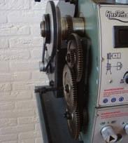
16 5.3. Gear box Figure 4 Gear box The gear box is mounted on the left side of the bed. The knobs on the gear box are used, to select the feed for turning and thread cutting Carriage Figure 5 Carriage The slide parts of the carriage are smoothly ground. They fit the V on the bed without play. De cross slide is mounted on the carriage and moves on a dove tailed slide. Play in the cross slide may be adjusted with gibs. The cross slide is moved by turning the hand wheel, which has been fitted with a graduated collar. The top slide is mounted on the cross slide and can be rotated 360º. The top slide and cross slide travel move over dove tail guides and have gibs and graduated collars. A four way tool post is fitted on the top slide and allows four tools to be clamped. Loosen the center clamp handle to rotate any of the four tools into position Apron Figure 6 Apron The apron is mounted on the carriage. It houses the half nut with an engaging lever for activating the automatic feed. The half nut gibs can be adjusted from the outside. The movement of the apron is transmitted by a rack and a pinion that are mounted on the bed Lead screw Figure 7 Lead screw The lead screw is mounted on the front of the bed. It is connected to the gear box at the left for automatic feed and is supported by bearing on both ends. Two groove nuts (A) on the right take up play on the lead screw Tailstock Figure 8 Tailstock The tailstock slides on a V-way and can be clamped at any location. The tailstock has a sturdy MT2-spindle with a graduated scale (in mm). The spindle can be clamped at any location with a clamping lever. It is moved by means of the hand wheel on the tailstock. Note! Fit the securing screw (B, fig. 7) always at the end on the right of the machine. This will prevent the tailstock of falling of the bed. 6. Control elements A. Emergency switch + On/off switch (fig. 9): The machine is switched On and Off with the On/Off switch. This switch can be found underneath the cover of the Emergency switch. Only push the Emergency switch when an emergency occurs, all machine functions will be stopped. To restart after an emergency, lift the cover and press the ON button. B. Switch for changing spindle rotation (fig. 9): After the machine is switched on, turn the switch to the F position for counter-clockwise spindle rotation (Forward). Turn the switch to R (Reverse) to make the spindle turn to the right. Position 0 means OFF, the spindle remains idle. C. Variable speed control switch (fig. 9): Turn the switch clockwise to increase the spindle speed, turn to the left to decrease the spindle speed. The speed range depends on the position of the V-belt. D. Feed direction selector (fig. 10): Select the carriage travel direction, it depends on the rotating direction of the jaw chuck. E. Feed rate selector (fig. 10): Use this switch to select the feed for threadcutting. F. Lock (fig. 11): Turn the nuts clockwise to lock, counter-clockwise to release. G. Compound slide lock (fig. 11): Turn the nuts clockwise to lock, turn counter-clockwise to release. H. Cross slide lock (fig. 11): Turn the screw clockwise and tighten to lock. Loosen the screw and turn it counterclockwise to release. 16
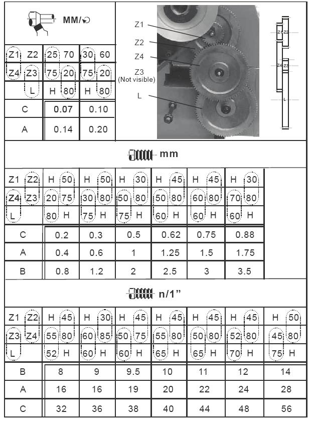
17 A. Carriage lock (fig. 12): Turn the screw (A) clockwise to tighten to lock the carriage. Turn counter-clockwise and loosen to release the carriage. Note! The bolts must be loosened, before automatic feed may be activated. B. Longitudinal slide travel (fig. 13): Turn the hand wheel clockwise to move the apron toward the tailstock. Turn the hand wheel counter-clockwise to move the apron toward the headstock. C. Half nut engage lever (fig. 13): Push the lever down to engage, push the lever up to disengage. D. Hand wheel of cross slide (fig. 13): Turn the hand wheel clockwise to move the cross slide toward the rear of the machine. E. Compound rest traverse lever (fig. 13): Rotate clockwise or counter-clockwise to place in the right position. F. Tool post clamping lever (fig. 13): Rotate the lever counter-clockwise to release, clockwise to clamp. The tool holder can be turned after the lever has been rotated counter-clockwise. G. Tailstock clamping screw (fig. 14): Rotate clockwise to clamp, counter-clockwise to release the tailstock. H. Tailstock spindle clamping lever (fig. 14): Rotate clockwise to lock the spindle, counter-clockwise to release. I. Tailstock spindle hand wheel (fig. 14): Rotate the hand wheel counter-clockwise to retract the spindle, clockwise to advance it. J. Set screws tailstock (fig. 14): Three set screws are located on the tailstock base to off-set the tailstock for cutting tapers. Loosen the screw at the end of the tailstock. Loosen 1 screw at the side and tighten the other screw until the right set-off on the scale is reached. Tighten the screw. 7. Operation 7.1. Replacing 3-jaw chuck The 3-jaw chuck is mounted to the chuck flange by means of 3 set screws and nuts (A, fig. 15). Loosen these screws and nuts if the jaw chuck has to be replaced. Make sure that the surfaces of the new jaw chuck and the chuck flange are clean before u mount the new jaw chuck with the nuts and screws Tool set-up Place the tool in the tool holder and clamp it firmly. When turning, the tool has the tendency to bend under the cutting force generated. For best results, tool overhang should be kept to a minimum of 9.5 mm or less. The cutting angle is correct when the cutting edge is in line with the center axis of the work piece. The correct height of the tool can be achieved by comparing the tool point with the point of the center mounted in the tailstock. If necessary, use steel spacer shims under the tool to get the required height (fig. 16) Changing speed Loosen the 2 fastening screws (B, fig. 17) and remove the cover. Loosen the nut (C, fig. 18) on the tension pulley holder (D) and reduced the tension of the V-belt (E). Adjust the V-belt to the right position and choose the right tension. Tighten the nut again. Replace the cover and tighten the fastening screws Turning Manual Turn the hand wheels of the apron, cross slide or tool slide for longitudinal and cross travel (fig. 19) Automatic feed (Longitudinal travel and threadcutting) Use the knobs (A, fig. 20) to select the right feed direction and speed. Use the table (B) to select the correct feed speed for threadcutting. Replace the set of change gears if the required feed or thread pitch cannot be obtained. 17
18 7.5. Replacing change wheels Disconnect the machine from the power source. Loosen the 2 fastening screws and remove the cover. Loosen the fastening screw (C, fig 21) on the quadrant. Swing the quadrant (D) to the right. Loosen the bolt (E) of the lead screw or loosen the bolts of the quadrant to remove the change wheels from the front. Install the change wheels according to the feed and threadcutting table (fig. 22) and mount them on the quadrant. Swing the quadrant to the left until the gear wheels engage. Adjust the backlash by inserting a normal sheet of paper between the change wheels. Tighten the fastening screw on the quadrant. Reinstall the cover and tighten the screws. Connect the machine to the power source. 8. Using the machine 8.1. Straight turning Figure 23 Straight turning With straight turning, the tool feeds parallel to the axis of rotation of the work piece. The feed can be either manual or turning the hand wheel on the lathe saddle or the sop slide, or by activating the automatic feed. The cross feed for the depth cut is achieved by using the cross slide Facing and recesses Figure 24 Facing and recesses In the facing operation, the tool feed perpendicular to the axis of rotation of the work piece. The feed is made manually with the cross slide hand wheel. The cross feed for cut depth is made with the top slide or lathe saddle Turning between the centers Figure 25 Turning between the centers For turning between the centers, it is necessary to remove the jaw chuck. Fit the MT3 center into the spindle nose and the MT2 center into the tailstock. Mount the work piece fitted with the driver dog between the centers. The driver is driven by a catch or face plate. Note! Always use a small amount of grease on the tailstock center to prevent overheating Taper turning using tailstock off-set Work pieces to a side angle of 5 mm can be turned by off-setting the tailstock. The angle depends on the length of the work piece. Proceed as follows to off-set the tailstock: Loosen the fastening screw (A, fig. 26). Loosen the fastening screw (B). Loosen the front set screw (C) a couple of turns and tighten the rear set screw (D) the same amount of turns. Repeat this until the required angle is reached. The value can be read on the scale. Tighten the set screw (B) and the front (C) and rear (D) set screws to secure the tailstock in this position. Tighten the set screw (A). The work pieces must be held between the centers and drive by a face plate and driver dog. After taper turning, return the tailstock to its original postion as indicated on the scale (E) of the tailstock Taper turning by setting the top slide Figure 27 Taper turning by setting the top slide By angling the top slide, tapers may be turned manually with the top slide. Rotate the top slide to the required angle. A graduated scale permits accurate adjustment of the top slide. The cross feed is performed with the cross slide. This method can only be used for short tapers. 18
19 8.6. Thread cutting Figure 28 Thread cutting Set the machine to the desired thread pitch. Switch the machine on and close the half nut. When the tool reaches the work piece, it will cut the initial threading pass. When the tool reaches the end of the cut, switch the machine off and at the same time move the tool out of the cut. Do not open the half nut! Reverse the motor direction to make the tool return to the starting point. Repeat these steps until the desired result is obtained. Advice for thread cutting The work piece diameter must compare to the diameter of the required thread. The work piece requires a chamfer of 45º at the beginning of the thread and an undercut at the thread run out. Speed must be as low as possible. Use the right combination of change wheels and adjustments to obtain the required thread pitch. The thread cutting tool must be exactly the same shape as the thread, must be rectangular and clamped so that it coincides exactly with the turning center. The thread is cut in steps so that the cutting tool has to be turned out of the thread completely (with the cross slide) at the end of each cutting step. The tool is withdrawn with the half nut engaged by using the on/off switch. Switch the machine off. Feed the thread cutting tool in low cut depths using the cross slide. Before each passage, place the top slide approximately 0.02 to 0.03 mm to the left and right alternately in order to cut the thread free. This way, the thread cutting tools cut only one thread flank with each passage. Keep cutting the thread free until you have almost reached the full depth of thread. 9. Accessories jaw chuck This 3-jaw chuck can be used to clamp round, triangular, square, hexagonal. octagonal and twelve-cornered work pieces. Note! New 3-jaw chucks have very tight fitting jaws. This is necessary to ensure accurate clamping and long service life. With repeated opening and closing, the jaw adjust automatically and their operation becomes smoother. Note The original 3-jaw chuck has been mounted with tow 0 marks (A, fig. 29) on the chuck and chuck flange. There are two types of jaws: internal and external jaws. Please note that the number of jaws matches the number inside the chuck s groove. When you are going to mount them, please mount them in the ascending order (as indicated on the jaws), dismounting takes place in the reverse order After you have finished the procedure, rotate the jaws to the smallest diameter and check that the three jaws are well fitted Independent 4-jaw chuck This chuck has 4 independently adjustable jaws (fig. 30). These permit the holding of asymmetrical or cylindrical pieces Drill chuck (optional) Use the drill chuck to hold centering drills and twist drills in the tailstock (A, fig. 31) Arbor (optional) An arbor is necessary for mounting the drill chuck in the tailstock. It has a MT2 taper (B, fig. 31) Steady center (optional) The steady center is mounted in ball bearings. Its use is highly recommended for turning at speeds in excess of 600 RPM (fig. 32). 19
20 9.6. Steady rest The steady rest (fig. 33) serves as a support for shafts on the free tailstock end. For many operations, the tailstock can not be used as it obstructs the turning tool or machine. The steady rest, which functions as an end support, ensures chatter-free operation. The steady rest is mounted on the bed ways and is secured from below with a locking plate. The sliding fingers require continuous lubrication at the contact points to prevent premature wear Mounting stead rest Loosen the 3 hex nuts (A, fig. 34). Loosen the knurled screw (B) and open the sliding fingers (C) until the steady rest can be moved with its fingers around the work piece. Secure the steady rest in this position. Tighten the knurled screw until the sliding fingers touch the work piece. The fingers may not clamp the work piece. Tighten the 3 nuts. Lubricate the fingers with machine oil. When after prolonged operation the jaw shows wear, the tips of the fingers may be filed or sharpened Follow rest The follow rest (fig. 35) is mounted on the carriage and follows the movement of the tool. The follow rest has two sliding fingers. The place of the third finger is taken by the tool. The follow rest is used for turning operations on long slender work pieces. It prevent flexing of the work piece under pressure from the turning tool. Set the fingers snug to the work piece but not overly tight. Lubricate the fingers during operation to prevent premature wear. 10. Adjustment After a period of time, wear in some of the moving components has to be re-adjusted Main spindle bearings The main spindle bearing were adjusted in the factory. If end play becomes evident after considerable use, the bearing may be adjusted. Loosen the screws (A, fig. 36) in the slotted nut (B) on the back of the spindle. Tighten the slotted nut until all the end play is taken up. The spindle should still move freely. Tighten the screws (A) again. Warning! Excessive tightening or preloading will damage the bearings or will damage the motor because of overheating Cross slide/top slide Figure 37 Cross slide Figure 38 Top slide Each slide is fitted with a gib strip (C/F) which can be adjusted with the screws (D/G). These screws are fitted with lock nuts (E/H). Loosen the lock nuts and tighten the screws, until the slide can be moved freely without play. Tighten the lock nuts to retain this adjustment Half nut Loosen the nuts (I, fig. 39) on the right of the apron and turn the screws (J) until both half nuts move freely without play. Tighten the nuts again. 20
21 11. Maintenance Lubrication Warning! All the oil reservoirs must be filled till the right level before the machine is used for the first time. Also, all lubrication points have to be lubricated. Gear box: Fill with Mobilgear 627 or equivalent till the level as indicated on the oil sight glass (A, fig. 40). Remove the drain plug (B) on the right of the headstock (C, fig. 41) to drain the oil from the machine. Drain the oil after the first 3 months of use and refill. Change wheels: Lubricate the 2 points (D, fig. 41) on the shafts every day with 20W machine oil. Carriage: Lubricate the 4 points (E, fig. 42) every day with 20W machine oil. Top slide: Lubricate the lubrication point ( (F) every day with 20W machine oil. Cross slide: Lubricate the 2 points (G) every day with 20W machine oil. Apron: Lubricate the lubrication point (H, fig. 43) every day with 20W machine oil. Lead screw: Lubricate the lubrication point (A, fig. 44) every day with 20W machine oil. Tailstock: Lubricate the 2 points (B) every day with 20W machine oil Electrical connections Figure 45 Electrical scheme Warning! The machine may only be connected to the mains by a qualified electrician. The lathe is rated at 0.75 kw. Check before the machine is connected to the mains, if the electrical specification of the machine and power source match Maintenance In order to retain the machine s precision and functionality, it is essential to treat it with care, keep it clean and grease and lubricate regularly. Only through good maintenance, the working quality of the machine will remain constant. Warning! Disconnect the machine from the power source before performing maintenance or repairs. These tasks may only be performed by qualified technicians. Note! Oil, grease and cleaning agents are pollutants and must not be disposed of through the drains or in normal refuse. Dispose of the agents in accordance with current legal requirements on the environment. Cleaning rags impregnated with oil, grease and cleaning agents are easily inflammable. Collect cleaning rags or cleaning wool in a suitable closed vessel and dispose of them in an environmentally sound way. Lubricate all slide ways slightly at the end of every shift. The change wheels and the leadscrew must also be lubricated with lithium based grease. Remove the chips every day and clean the machine. Lubricate the bare parts slightly afterwards. Warning! Never remove chips with your bare hand. Never use highly inflammable substances. Never use the machine in a damp environment. Replace damaged or worn down parts immediately. 21
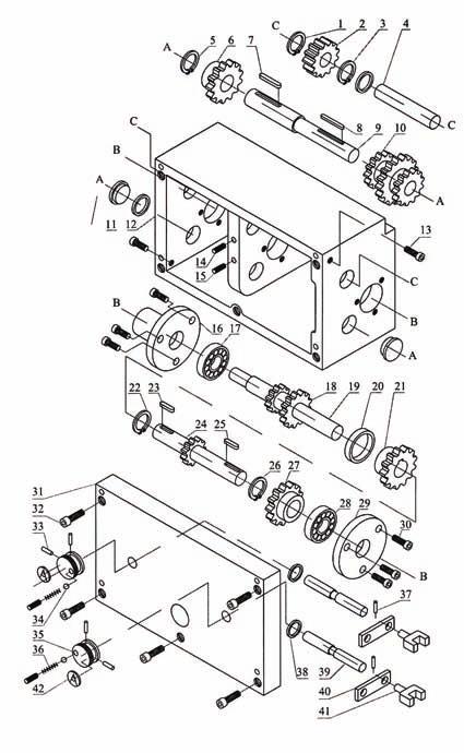
22 12. Troubleshooting Problem Possible cause Possible solution Surface of work piece too Tool blunt Resharpen tool rough Tool springs Clamp tool with less overhanging Feed too high Reduce feed Radius at tool tip too small Increase radius Work piece becomes coned Centers are not aligned (offset tailstock) Adjust tailstock to the center Top slide not at 0-mark when cutting Align top slide to 0 Lathe chatters Feed too high Reduce feed Play on main spindle bearings Adjust main spindle bearings Center runs hot Work piece has expanded Loosen tailstock center Tool has a short edge life Cutting speed too high Reduce cutting speed Feed too high Reduce feed Insufficient cooling More coolant Flank wear too high Clearance angle too small Increase clearance angle Tool tip not adjusted to center high Correct height adjustment of tool Cutting edge breaks off Wedge angle too small Increase wedge angle Grinding crack due to wrong cooling Cool sufficiently Excessive play in spindle bearing Adjust play Cut thread is wrong Tool clamped incorrectly Adjust tool to the center Wrong pitch Adjust Wrong diameter Turn work piece to correct diameter Spindle not active Emergency stop activated Unlock emergency switch 13. Spare parts Figure 46 Headstock No. Description Specification Quantity 1 Label 1 2 Screw ø 4 x Bolt 2 4 Nut M Nut M Spindle 1 7 Key 8 x Gasket 1 9 Bearing 1 10 Headstock 1 11 Nut M Washer ø Screw M8 x Bearing E 1 15 Gasket 1 16 Bush 1 17 Gear 1 19 Belt 1 20 Spindle pulley 2 21 Set screw M5 x Washer 2 23 Nut 1 24 Screw 4 25 Bracket 1 26 Screw 4 27 Washer 4 28 Motor 1.0 kw 1 30 Motor pulley 1 22
23 No. Description Specification Quantity 31 Washer 1 32 Set screw 1 33 Washer 1 34 Nut 1 35 Bolt 1 36 Base 1 37 Bolt 1 38 Bearing M8 x Roller 1 40 Snap ring 1 Figure 47 Gear box No. Description Specification Quantity 1 Snap ring ø Gear 1 3 Snap ring 1 4 Shaft 1 5 Snap ring ø Gear 1 7 Key 4 x Key 4 x Shaft 1 10 Gear 1 11 Drain plug 1 12 Gear box 1 13 Screw 1 14 Screw M6 x Screw M6 x Flange 1 17 Bearing 1 19 Gear 1 20 Shaft 1 21 Separator 1 22 Gear ø Snap ring 4 x Key 1 25 Shaft 4 x Snap ring ø Gear 1 28 Bearing 1 29 Flange 1 30 Screw M6 x Cover 1 32 Screw 1 33 Pin 1 34 Ball ø Knob 2 36 Spring 2 37 Pin ø 5 x Seal ring 1 39 Shaft 1 40 Bracket 2 41 Fork 2 42 Label 2 23
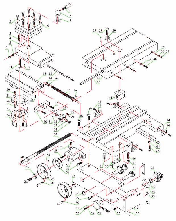
24 Figure 48 Slides No. Description Specifications Quantity 1 Handle 1 2 Screw 8 3 Top slide 1 4 Pin ø 4 x Screw 3 6 Nut M6 3 7 Handle base 1 8 Washer 1 9 Tool holder 1 10 Pin 1 11 Stift 1 12 Key 1 13 Swivel base 1 14 Nut 1 15 Lead screw 1 16 Key 1 17 Screw 1 18 Zero indicator 1 19 Handle 1 20 Nut 2 21 Snap ring 1 22 Screw 2 23 Graduated collar 1 24 Screw 4 25 Pin 1 26 Nut 2 27 Screw 1 28 Screw 1 29 Bush 1 30 Bracket 1 31 Graduated collar 1 32 Hand wheel 1 34 Nut 1 35 Pin 1 36 Screw M4 x Nut 3 39 Pin 3 40 Screw M8 x Cross slide 1 42 Key 1 44 Nut 1 45 Screw 2 46 Wiper 1 47 Lock screw 1 48 Screw 2 50 Lead screw 1 53 Screw 1 54 Spring 1 55 Washer 1 56 Bracket 1 57 Screw 1 58 Graduated collar 1 24
25 No. Description Specifications Quantity 59 Hand wheel 1 60 Handle 1 61 Carriage 1 62 Wiper 1 63 Gib 1 64 Nut 1 65 Screw 1 66 Screw 1 67 Nut 1 68 Screw 1 69 Clamping plate 1 70 Gear shaft 1 71 Gear shaft 1 72 Half nut 1 73 Plate 1 74 Cam 1 75 Snap ring 1 76 Snap ring 1 78 Graduated collar 1 79 Screw 1 80 Handle 1 81 Ball 1 82 Screw 1 83 Spring 1 84 Hand wheel 1 85 Screw 1 86 Apron 1 87 Screw 1 Figure 49 Tailstock and bed No. Description Specification Quantity 1 Handle 1 2 Screw 1 3 Oil cup 1 4 Zero indicator 1 5 Washer 2 6 Sleeve 1 7 Lead screw 1 8 Bush 1 9 Key 1 10 Spring 1 11 Hand wheel 1 12 Nut 1 14 Graduated collar 1 15 Handle 1 16 Nut 1 17 Washer 1 18 Tailstock body 1 19 Base 1 20 Screw 2 21 Clamping plate 1 22 Bolt 1 27 Nut 2 25
26 No. Description Specification Quantity 28 Washer 2 29 Screw 2 30 Bed 1 31 Rack 2 32 Screw 6 33 Lead screw 1 34 Screw 1 35 Screw 1 36 Nut 1 37 Bracket 1 38 Bearing 1 39 Bearing 1 26
27 27
28 Our products are frequently updated and improved. Minor changes may not yet be incorporated in this manual. Always state the year of build, type and serial number of the machine in correspondence. Manufacturer and importer assume no responsibility for defects which result from not reading the manual carefully or wrong use of the machine. No rights can be derived from this manual. All rights reserved. No part of this booklet may be reproduced in any form, by print, photoprint, microfilm or any other means without written permission from the publisher. Huberts bv, Kennedylaan 14, Veghel, the Netherlands. Internet: 28
29 CE DECLARATION OF CONFORMITY (in accordance with supplement II A of the Machinery Directive) Industrie & Handelsonderneming Huberts bv, Kennedylaan 14, 5466 AA Veghel, the Netherlands, in the capacity of importer, is to be held responsible for declaring that the Huvema machine: Lathe HU 700 Vario which this declaration relates to, is conform the following norms: NEN-EN-ISO 12100:2010, NEN-EN-IEC :2006/C11:2010, NEN-EN-IEC : 2007, NEN-EN-IEC :2007/A1:011/C11:2012, NEN-EN-ISO 23125:2010 and meets the basic requirements of the: Machinery Directive 2006/42/EC Electromagnetic Compatibility directive 2004/108/EC Low Voltage directive 2006/95/EC Veghel, the Netherlands, March 2014 L. Verberkt Managing director 29
30 30
31 31
32 2014 V1
L AT H E HU 300 VARIO
 LATHE HU 300 VARIO 1 2 3 4 5 6 7 2 8 9 10 11 12 13 14 15 3 16 17 18 4 19 20 21 22 23 24 25 26 27 28 5 29 30 31 32 33 34 35 36 6 37 7 38 8 39 9 40 10 41 11 42 12 Table of contents 1. General safety rules
D R I L L - G R I N D E R S BL 13D-2
 D R I L L - G R I N D E R S BL 13D-2 2 Table of contents 1. General safety rules for all machines 3 2. Additional safety rules 4 3. Features 4 4. Specification 4 5. Operation 4 5.1 Assemble the fixture
WARNING! Read and understand the entire instruction manual before attempting set-up or operation of this machine!
 ! WARNING! Read and understand the entire instruction manual before attempting set-up or operation of this machine! 1. This machine is designed and intended for use by properly trained and experienced
V BELT DRIVEN DRILLING MACHINES HU 16-2 TOPLINE HU 16-4 TOPLINE
 V BELT DRIVEN DRILLING MACHINES HU 16-2 TOPLINE HU 16-4 TOPLINE 1 2 4 3 5 Fig. A - Main parts Fig. 1 Fig. 3 Fig. 2 2 CHANGES AND TYPING ERRORS RESERVED Fig. 4 Fig. 5 Fig. 7 Fig. 6 Fig. 8 Fig. 9 CHANGES
VARIABLE SPEED WOOD LATHE
 MODEL MC1100B VARIABLE SPEED WOOD LATHE INSTRUCTION MANUAL Please read and fully understand the instructions in this manual before operation. Keep this manual safe for future reference. Version: 2015.02.02
VARIABLE SPEED WOOD LATHE. Model DB900 INSTRUCTION MANUAL
 VARIABLE SPEED WOOD LATHE Model DB900 INSTRUCTION MANUAL 1007 TABLE OF CONTENTS SECTION...PAGE Technical data.. 1 General safety rules....1-3 Specific safety rules for wood lathe.....3 Electrical information.4
TB & SB Series Drill Presses
 TB & SB Series Drill Presses OWNERS MANUAL BENCH AND FLOOR DRILL PRESS TB-16 Series & SB-16-25-32-Series FOR YOUR OWN SAFETY AND OPTIMUM OPERATION READ INSTRUCTION MANUAL BEFORE OPERATING DRILL PRESS RETAIN
Assembly Instructions and Parts Manual 5C Collet Closer for ZX Series Lathes Model CC-ZX
 Assembly Instructions and Parts Manual 5C Collet Closer for ZX Series Lathes Model CC-ZX JET 427 New Sanford Road LaVergne, Tennessee 37086 Part No. M-321292 Ph.: 800-274-6848 Revision B 03/2014 www.jettools.com
Assembly Instructions and Parts Manual 5C Collet Closer for GHW Lathes Model CC-GHW
 Assembly Instructions and Parts Manual 5C Collet Closer for GHW Lathes Model CC-GHW JET 427 New Sanford Road LaVergne, Tennessee 37086 Part No. M-321519 Ph.: 800-274-6848 Revision G1 03/2014 www.jettools.com
GENERAL OPERATIONAL PRECAUTIONS PRECAUTIONS ON USING CUT-OFF MACHINE
 GENERAL OPERATIONAL PRECAUTIONS WARNING! When using electric tools, basic safety precautions should always be followed to reduce the risk of fire, electric shock and personal injury, including the following.
Tapping Screw (W/Flange) 46 Cord Armor 47 Tube (D) 48 Cord. 45 Cord Clip. Tapping Screw (W/Flange) 10 Gear Cover Ass'y. 12 Socket (B) Ass'y
 46 Cord Armor 47 Tube (D) 48 Cord. 45 Cord Clip. Tapping Screw (W/Flange) 10 Gear Cover Ass'y. 12 Socket (B) Ass'y") W8VB The exploded assembly drawing should be used only for authoized service center. W8VB Item No. Part time 1 Magnetic Hex. Socket 2 Sub Stopper 3 O-Ring (S-16) 4 Locator (A) 5 Lock Sleeve (A) 6 O-Ring
W8VB The exploded assembly drawing should be used only for authoized service center. W8VB Item No. Part time 1 Magnetic Hex. Socket 2 Sub Stopper 3 O-Ring (S-16) 4 Locator (A) 5 Lock Sleeve (A) 6 O-Ring
OPERATOR S HANDBOOK WM180. Warren Machine Tools Ltd
 OPERATOR S HANDBOOK WM180 Warren Machine Tools Ltd Warco House, Fisher Lane, Chiddingfold,Surrey GU84TD Tel: 01428 682929 Fax: 01428 685870 E-mail: warco@warco.co.uk Web www.warco.co.uk NOTE The information
GH-1340B(C6232B2) GH-1440B(C6236B2) GEARED HEAD PRECISION LATHE
 GH-1440B(C6236B2) GEARED HEAD PRECISION LATHE") GH-1340B(C6232B2) GH-1440B(C6236B2) GEARED HEAD PRECISION LATHE OPERATOR S MANUAL WARNING! 1. Read and understand the entire instruction manual before operating machine. 2. Always wear approved safety
GH-1340B(C6232B2) GH-1440B(C6236B2) GEARED HEAD PRECISION LATHE OPERATOR S MANUAL WARNING! 1. Read and understand the entire instruction manual before operating machine. 2. Always wear approved safety
 GENERAL OPERATIONAL PRECAUTIONS WARNING! When using electric tools, basic safety precautions should always be followed to reduce the risk of fire, electric shock and personal injury, including the following.
x 43 Wood Lathe
 Please dispose of packaging for the product in a responsible manner. It is suitable for recycling. Help to protect the environment, take the packaging to the local amenity tip and place into the appropriate
Variable Speed Cast Iron Midi Wood Lathe
 01936 Variable Speed Cast Iron Midi Wood Lathe Please read and fully understand the instructions in this manual before operation. Keep this manual safe for future reference. 1 Technical Data Input voltage
12mm (Max) 6mm (Max) 82mm (Max) 12mm (Max) 6mm (Max)
 6mm (Max) 82mm (Max) 12mm (Max) 6mm (Max)") 1 1 2 2 3 3 82mm (Max) 12mm (Max) 12mm (Max) 6mm (Max) 4 4 5 6 8 6mm (Max) 0.5 0mm 1 5 6 7 7 8 9 9 A = B 10 11 12 D B 1 13 14 15 0 C A D E 16 17 18 F G D B N H J G I K 19 A 20 G L 21 C K 1mm L M 1mm 22
1 1 2 2 3 3 82mm (Max) 12mm (Max) 12mm (Max) 6mm (Max) 4 4 5 6 8 6mm (Max) 0.5 0mm 1 5 6 7 7 8 9 9 A = B 10 11 12 D B 1 13 14 15 0 C A D E 16 17 18 F G D B N H J G I K 19 A 20 G L 21 C K 1mm L M 1mm 22
PM-1440HD LATHE OPERATION MANUAL
 PM-1440HD LATHE OPERATION MANUAL WARNING! 1. Read and understand the entire instruction manual before attempting assembly or operation. 2. These lathes are designed and intended for use by properly trained
01950 Heavy Duty Floor Standing Morticer with Cabinet
 Please dispose of packaging for the product in a responsible manner. It is suitable for recycling. Help to protect the environment, take the packaging to the local amenity tip and place into the appropriate
GEARED HEAD DRILL / MILL MACHINE INSTRUCTION MANUAL
 www.industrialtool.com.au GEARED HEAD DRILL / MILL MACHINE INSTRUCTION MANUAL READ CAREFULLY AND UNDERSTAND THESE INSTRUCTIONS BEFORE USE. LIMITED WARRANTY Industrial Tool & Machinery Sales (hereinafter
ELECTRIC SLIP ROLL MACHINE. Model: ESR-1300X2.5/ESR-1300X4.5 ESR-1550X3.5/ESR-1580X2.0
 ELECTRIC SLIP ROLL MACHINE Model: ESR-1300X2.5/ESR-1300X4.5 ESR-1550X3.5/ESR-1580X2.0 Operation Manual Table of contents I MAIN SPECIFICATION...2 II SAFETY INSTRUCTIONS.. 2 III OPERATION INSTRUCTIONS..4
GENERAL OPERATIONAL PRECAUTIONS PRECAUTIONS ON USING DISC GRINDER
 GENERAL OPERATIONAL PRECAUTIONS WARNING! When using electric tools, basic safety precautions should always be followed to reduce the risk of fire, electric shock and personal injury, including the following.
VARIABLE SPEED BECH LATHE
 VARIABLE SPEED BECH LATHE Instruction Manual Please read this instruction manual thoroughly and follow all directions carefully. 1 Important Safety Instructions READ ALL INSTRUCTIONS AND WATNINGS BEFORE
x 36 Wood Lathe
 Please dispose of packaging for the product in a responsible manner. It is suitable for recycling. Help to protect the environment, take the packaging to the local amenity tip and place into the appropriate
MI MI OPERATING MANUAL
 MODEL NO.: MI-76100 MI-76150 OPERATING MANUAL RULES for SAFE OPERATION MAGNUM INDUSTRIAL MI-76100 and MI 76150 DRILL PRESSES To help ensure safe operation, please take a moment to learn the how to operate
SB-32V Drill Press OWNERS MANUAL
 724 Robbins Road, Grand Haven, MI 49417 Phone: 616-842-7110 800-937-3253 Fax: 616-842-0859 800-846-3253 Web: www.dakecorp.com E-mail: customerservice@dakecorp.com SB-32V Drill Press OWNERS MANUAL FOR YOUR
INSTRUCTION BOOKLET AND WARRANTY INFORMATION 6 BENCH GRINDER
 INSTRUCTION BOOKLET AND WARRANTY INFORMATION 6 BENCH GRINDER Part No.: SW1250 PLEASE READ CARE AND SAFETY INSTRUCTIONS BEFORE USE SPECIFICATIONS Part No.: SW1250 Input Voltage: 240V Frequency: 50Hz Rated
GENERAL OPERATIONAL PRECAUTIONS
 GENERAL OPERATIONAL PRECAUTIONS WARNING! When using electric tools, basic safety precautions should always be followed to reduce the risk of fire, electric shock and personal injury, including the following.
Angle Grinder MODEL 9553B MODEL 9555B
 ENGLISH Angle Grinder MODEL 9553B MODEL 9555B 006649 DOUBLE INSULATION I N S T R U C T I O N M A N U A L WARNING: For your personal safety, READ and UNDERSTAND before using. SAVE THESE INSTRUCTIONS FOR
Electric Router. Please read and fully understand the instructions in this manual before operation and keep this manual safe for future
 Electric Router FOR HELP OR ADVISE ON THIS PRODUCT PLEASE CALL OUR CUSTOMER SERVICE HELP LINE : 0509 500400 THE MANUFACTURER RESERVES THE RIGHT TO ALTER THE DESIGN OR SPECIFICATION TO THIS PRODUCT WITHOUT
INSTRUCTION MANUAL. Lathe Duplicator MODEL North Glenn Road, Casper, Wyoming woodworker.com
 140-069LatheDuplictr(1/12) 10/30/06 8:20 AM Page 1 INSTRUCTION MANUAL Lathe Duplicator MODEL 140-069 1108 North Glenn Road, Casper, Wyoming 82601 1-800-645-9292 woodworker.com 140-069LatheDuplictr(1/12)
Instructions for Stone Cutting Machine
 Technical data Kg. Instructions for Stone Cutting Machine SCM600 3HP 2800rpm IP55 SCM800 3HP 2800rpm IP55 SCM1000 2800rpm IP55 SCM1200 2800rpm IP55 L=600 B=85(165) L=800 B=85(175) 500x510 0 or 45 600lt/h
GENERAL OPERATIONAL PRECAUTIONS
 GENERAL OPERATIONAL PRECAUTIONS WARNING! When using electric tools, basic safety precautions should always be followed to reduce the risk of fire, electric shock and personal injury, including the following.
Cut-Off Machine Model CC 14SE
 Cut-Off Machine Model CC 14SE Handling instructions NOTE: Before using this Electric Power Tool, carefully read through these HANDLING INSTRUCTIONS to ensure efficient, safe operation. It is recommended
SECTION 10: PARTS. Headstock
 33 32 31 30 7 SECTION 10: PARTS 34 23 36 22 15 14 12 35 37 48 39 41 42 50 40 25 38 38 26 39 42 44 41 25 26 40 51 43 52 10 5 53 9 4 1 27 2 21 19 20 Headstock 8 16 11 17 18 14 13 7 6 45 47 46 3 1 P0768001
SECTION 9: PARTS. Headstock
 SECTION 9: PARTS We do our best to stock replacement parts when possible, but we cannot guarantee that all parts shown are available for purchase. Call (800) 52-4777 or visit www.grizzly.com/parts to check
Twist Drill Grinder. Operation Manual. Model : GS-21 / GS-34
 Twist Drill Grinder Operation Manual Model : GS-21 / GS-34 RECYCLING Do not dispose of electrical appliances as unsorted municipal waste, use separate collection facilities. Contact your local government
# x 12 Wood Turner s Lathe
 #86892 8 x 12 Wood Turner s Lathe Please read and understand all instructions before using this tool. Note: These instructions will show you how to assemble this machine, work its controls and maintain
SECTION 10: PARTS. Headstock
 33 32 31 30 7 SECTION 10: PARTS 34 23 36 22 15 14 12 35 37 48 39 41 42 50 40 25 38 38 26 39 42 44 41 25 26 40 51 43 52 10 5 53 9 4 1 27 2 21 19 20 Headstock 8 16 11 17 18 14 13 7 6 45 47 46 3 1 P0768001
Twist Drill Grinder. Operation Manual. Model : GS-20
 Twist Drill Grinder Operation Manual Model : GS-20 RECYCLING Do not dispose of electrical appliances as unsorted municipal waste, use separate collection facilities. Contact your local government for information
HOLE CUTTER SHARPENER ASSEMBLY & SERVICE MANUAL
 HOLE CUTTER SHARPENER ASSEMBLY & SERVICE MANUAL WARNING You must thoroughly read and understand this manual before operating the equipment, paying particular attention to the Warning & Safety instructions.
Record the serial number and date of purchase in your manual for future reference.
 Mini Lathe Model: 70-100 Owner s Manual Record the serial number and date of purchase in your manual for future reference. Serial number: Date of purchase: Part # 70-100M1 For more information: www.rikontools.com
Horizontal and Vertical. Metal Cutting Band Saw MODEL: BS-115
 Horizontal and Vertical Metal Cutting Band Saw MODEL: BS-5 SAFETY. Know your band saw. Read the operator s Manual carefully. Learn the operations, applications and limitation.. Use recommended accessories.
Power Planer 1900B/N1900B/1902
 Power Planer 1900B N1900B 1902 SPECIFICATIONS Model 1900B/N1900B/1902 Planing width... 82 mm Planing depth... 1 mm Shiplapping depth... 9 mm No load speed (min -1 )...16,000 Overall length... 290 mm Net
MICRO Shaper MT 300 Manual
 70 0 ProxxonTools.com MICRO Shaper Manual 0 0 70 U = V~ 70 0 0 0 U = V~ 70 U = V~ U = V~ U = V~ n = 6.000/min Messerwelle Breite = mm max U = V~ 4 7 9 3 3 6 4 5 Fig. Fig. Fig 8 4 3 Fig. Fig. 3a Fig. 3b
CX704 7 x 12 MINI METAL LATHE User Manual
 CX704 7 x 12 MINI METAL LATHE User Manual TABLE OF CONTENTS General Safety Instructions... 3 Specific Safety Instructions... 4 Features... 5 Physical Features... 6 Set-Up... 7 Un-Packing... 7 Proper Grounding...
Quick Set Dovetail Jig
 Quick Set Dovetail Jig FOR HELP OR ADVISE ON THIS PRODUCT PLEASE CALL OUR CUSTOMER SERVICE HELP LINE : 01509 500359 THE MANUFACTURER RESERVES THE RIGHT TO ALTER THE DESIGN OR SPECIFICATION TO THIS PRODUCT
SECTION 9: PARTS. Headstock A 126A 127A-1 REF PART # DESCRIPTION REF PART # DESCRIPTION
 SECTION 9: PARTS Headstock 120 121 113 115 112 111 110 109 108 105 106 107 135 101 119A 121 120 118 114 115 107 106 104 123 122 118 114 126A 105 126 103 102 126B 127A-1 131 127A 124 133 134 126C 129 130
Trautman Carvers. Product Manual
 Trautman Carvers Product Manual Contents Product Specifications.... 4 Operating Precautions.... 6 Floor Carver Use.... 7 Floor Carver Diagram.... 10 Trautman Motor Lift Assist.... 11 Use of the Lift Assist....
MILLING/DRILLING ATTACHMENT
 MILLING/DRILLING ATTACHMENT Model No.CL251MH Part No. 7610741 OPERATING MAINTENANCE OPERATING & MAINTENANCE INSTRUCTIONS INSTRUCTIONS 0803 SPECIFICATIONS Motor... 230V 50Hz 1ph Power Rating... 150W Spindle
Recipro Saw MODEL JR3020. WARNING: For your personal safety, READ and UNDERSTAND before using. SAVE THESE INSTRUCTIONS FOR FUTURE REFERENCE.
 ENGLISH Recipro Saw MODEL JR3020 002479 DOUBLE INSULATION I N S T R U C T I O N M A N U A L WARNING: For your personal safety, READ and UNDERSTAND before using. SAVE THESE INSTRUCTIONS FOR FUTURE REFERENCE.
12 SHEAR, PRESS BRAKE &SLIPROLL
 12 SHEAR, PRESS BRAKE &SLIPROLL OPERATION MANUAL SPECIFICATION Cpacity: Roller : Die set sizes: Weight: 1mm thick (20gauge), 305 mm (12 ) width 38mm(1-1/2 ) 101.6mm(4 ), 76.2mm(3 ), 50.8mm (x2)[2 9x2]],
Assembly Instructions and Parts Manual Taper Attachment for Bench Lathes Model TAK-13GH/BD
 Assembly Instructions and Parts Manual Taper Attachment for Bench Lathes Model TAK-13GH/BD JET 427 New Sanford Road LaVergne, Tennessee 37086 Part No. M-321442 Ph.: 800-274-6848 Revision B 03/2014 www.jettools.com
Cut-Off Machine CC 14SF. Read through carefully and understand these instructions before use. Handling instructions
 Cut-Off Machine CC 14SF Read through carefully and understand these instructions before use. Handling instructions GENERAL OPERATIONAL PRES WARNING! When using electric tools, basic safety precautions
Precision made in Germany. As per DIN The heart of a system, versatile and expandable.
 1 Precision made in Germany. As per DIN 8606. The heart of a system, versatile and expandable. Main switch with auto-start protection and emergency off. Precision lathe chuck as per DIN 6386 (Ø 100mm).
ELECTRIC TUBE ROLLER
 41238-0000 ELECTRIC TUBE ROLLER OPERATING INSTRUCTIONS & SERVICE MANUAL Rev: A, 8/20/2007 TO REDUCE THE RISK OF INJURY AND EQUIPMENT DAMAGE USER MUST READ AND UNDERSTAND OPERATOR S MANUAL. Thomas C. Wilson,
12 Slip Roll. Model Assembly & Operating Instructions
 12 Slip Roll Model 36698 Assembly & Operating Instructions Diagrams within this manual may not be drawn proportionally. Due to continuing improvements, actual product may differ slightly from the product
ROTARY HAMMER OWNER'S MANUAL
 ROTARY HAMMER OWNER'S MANUAL WARNING: Read carefully and understand all INSTRUCTIONS before operating. Failure to follow the safety rules and other basic safety precautions may result in serious personal
ENGLISH (Original instructions) INSTRUCTION MANUAL. Drill MT600 MT601 DOUBLE INSULATION. IMPORTANT: Read Before Using.
 INSTRUCTION MANUAL. Drill MT600 MT601 DOUBLE INSULATION. IMPORTANT: Read Before Using.") ENGLISH (Original instructions) INSTRUCTION MANUAL Drill MT600 MT60 003635 DOUBLE INSULATION IMPORTANT: Read Before Using. ENGLISH (Original instructions) SPECIFICATIONS Model MT600 MT60 Capacities Steel
ENGLISH (Original instructions) INSTRUCTION MANUAL Drill MT600 MT60 003635 DOUBLE INSULATION IMPORTANT: Read Before Using. ENGLISH (Original instructions) SPECIFICATIONS Model MT600 MT60 Capacities Steel
PARTS. W1669 & W1670 Parts PARTS. Model W1669/W1670 (For Machines Mfd. Since 04/18) 66V A A A 28A
 66V A A A 28A") W1669 & W1670 Parts 23 66V2 22 21 25 26 53A 62 63 89 64 9 65 24 20 15 16A 54 93 10 16A-1 81 77 94 53 79 102 103 28 36 8 30 19 31 32 32-1 109 28A 28 27 34 33 56 49 76 76 19-3 19-1 19-2 38-1 89 35 60 59
W1669 & W1670 Parts 23 66V2 22 21 25 26 53A 62 63 89 64 9 65 24 20 15 16A 54 93 10 16A-1 81 77 94 53 79 102 103 28 36 8 30 19 31 32 32-1 109 28A 28 27 34 33 56 49 76 76 19-3 19-1 19-2 38-1 89 35 60 59
Circular Saw MODEL MT581. WARNING: For your personal safety, READ and UNDERSTAND before using. SAVE THESE INSTRUCTIONS FOR FUTURE REFERENCE.
 ENGLISH Circular Saw MODEL MT58 005337 DOUBLE INSULATION I N S T R U C T I O N M A N U A L WARNING: For your personal safety, READ and UNDERSTAND before using. SAVE THESE INSTRUCTIONS FOR FUTURE REFERENCE.
10 BANDSAW OPERATING INSTRUCTIONS MODEL: W715
 Machinery & Tooling at its best! 10 BANDSAW OPERATING INSTRUCTIONS MODEL: W715 Charnwood, Cedar Court, Walker Road, Bardon, Leicestershire, LE67 1TU Tel. 01530 516926 Fax. 01530 516929 email; sales@charnwood.net
18 GAUGE ELECTRIC METAL SHEAR
 241-9895 18 GAUGE ELECTRIC METAL SHEAR Operator s Manual SAVE THIS MANUAL You will need this manual for safety instructions, operating procedures and warranty. Put it and the original sales receipt in
SAVE THIS FOR FUTURE REFERENCE THIS PRODUCT IS FOR PROFESSIONAL LABORATORY USE ONLY USER'S MANUAL
 DENTAL, INC. TECHNICAL BULLETIN G801-022510 5860 FLYNN CREEK ROAD READ ALL INSTRUCTIONS P.O. BOX 106 BEFORE PROCEEDING COMPTCHE, CALIFORNIA, U.S.A. 95427-0106 SAVE THIS FOR FUTURE REFERENCE www.wellsdental.com
SALES CUSTOMER SERVICE TECHNICAL ASSISTANCE CALL TOLL-FREE:
 DENTAL, INC. TECHNICAL BULLETIN U802-022510 5860 FLYNN CREEK ROAD READ ALL INSTRUCTIONS P.O. BOX 106 BEFORE PROCEEDING COMPTCHE, CALIFORNIA, U.S.A. 95427 SAVE THIS FOR FUTURE REFERENCE THIS PRODUCT IS
Grizzly Drill Press SOP
 Grizzly Drill Press SOP Drill Press is wired to run on 0V. Drill Press has a built in light with a ON/OFF switch. Never hold a workpiece by hand while drilling. Clamp it down or hold it in a vice. Never
ENGLISH (Original instructions) INSTRUCTION MANUAL. Drill DOUBLE INSULATION. IMPORTANT: Read Before Using.
 INSTRUCTION MANUAL. Drill DOUBLE INSULATION. IMPORTANT: Read Before Using.") ENGLISH (Original instructions) INSTRUCTION MANUAL Drill 64 642 643 007894 DOUBLE INSULATION IMPORTANT: Read Before Using. ENGLISH (Original instructions) SPECIFICATIONS Model 64 642 643 Capacities Steel
ENGLISH (Original instructions) INSTRUCTION MANUAL Drill 64 642 643 007894 DOUBLE INSULATION IMPORTANT: Read Before Using. ENGLISH (Original instructions) SPECIFICATIONS Model 64 642 643 Capacities Steel
PLATE JOINER 4 INCH. ASSEMBLY and OPERATING INSTRUCTIONS. Distributed Exclusively by Harbor Freight Tools
 PLATE JOINER 4 INCH 38437 ASSEMBLY and OPERATING INSTRUCTIONS Distributed Exclusively by Harbor Freight Tools 3491 Mission Oaks Blvd., Camarillo, CA 93011 Copyright 1998 by Harbor Freight Tools. All rights
LBUFFSE. Pen Finishing Station. User s Manual. APPLICATIONS: Sanding, finishing or polishing of wood, acrylic, or polymer clay pen blanks.
 LBUFFSE Pen Finishing Station User s Manual APPLICATIONS: Sanding, finishing or polishing of wood, acrylic, or polymer clay pen blanks. WARRANTY This product is warranted against defects in materials and
The premier source of parts and accessories for mini lathes and mini mills. Mini Lathe User s Guide. from LittleMachineShop.com
 The premier source of parts and accessories for mini lathes and mini mills. Mini Lathe User s Guide from LittleMachineShop.com Copyright 2002, LittleMachineShop.com All rights reserved. Some photos Copyright
ET-110 EXTREMA MACHINERY COMPANY, INC. P.O. BOX 1450, ALBANY, LOUISIANA (877) FAX (225)
 FAX (225)") ET-0 EXTREMA MACHINERY COMPANY, INC. P.O. BOX 450, ALBANY, LOUISIANA 707 (877) 398-7362 FAX (225) 567-2966 PREFACE The XT-0 is precision built and manufactured to satisfy the highest standards. For maximum
ET-0 EXTREMA MACHINERY COMPANY, INC. P.O. BOX 450, ALBANY, LOUISIANA 707 (877) 398-7362 FAX (225) 567-2966 PREFACE The XT-0 is precision built and manufactured to satisfy the highest standards. For maximum
Electric Chainsaw Sharpener
 FPP CHAINSS Electric Chainsaw Sharpener Instruction Manual For your own safety, please ensure you have read these instructions before use and have fully understood all the safety guidelines. Specifications
ENGLISH (Original instructions) INSTRUCTION MANUAL. Shear Wrench 6922NB DOUBLE INSULATION. IMPORTANT: Read Before Using.
 INSTRUCTION MANUAL. Shear Wrench 6922NB DOUBLE INSULATION. IMPORTANT: Read Before Using.") ENGLISH (Original instructions) INSTRUCTION MANUAL Shear Wrench 69NB 00498 DOUBLE INSULATION IMPORTANT: Read Before Using. ENGLISH (Original instructions) SPECIFICATIONS Model 69NB Bolt size M6, M0, M
ENGLISH (Original instructions) INSTRUCTION MANUAL Shear Wrench 69NB 00498 DOUBLE INSULATION IMPORTANT: Read Before Using. ENGLISH (Original instructions) SPECIFICATIONS Model 69NB Bolt size M6, M0, M
MODEL 7000 BEVEL-MILL
 MODEL 7000 BEVEL-MILL HECK INDUSTRIES P.O. BOX 425 HARTLAND, MI 48353 TOLL FREE: 800-886-5418 PHONE: 810-632-5400 FAX: 810-632-6640 WWW.HECKIND.NET INSTRUCTION MANUAL Save This Manual You will need the
Hinge Boring/Insertion Machine Set Up And Operation Instructions
 Hinge Boring/Insertion Machine Set Up And Operation Instructions Manufactured In The USA By: Thompson Industries, Inc. 1018 Crosby Avenue, Sycamore, IL. 60178-0127 Ph:815-899-6670 Fax:815-899-1918 Thank
SECTION 9: PARTS Main
 -64- Model G0765 (Mfd. Since 5/15) 1 2 3 4 5 6 7 8 9 9 10 10 11 11 12 12 13 14 15 16 17 18 19 20 21 21 22 23 23 24 25 26 27 28 29 30 31 32 33 35 36 37 38 39 40 41 42 43 44 44 45 157 46 47 48 49 50 50 51
The premier source of tooling, parts, and accessories for bench top machinists. HiTorque Bench Lathe User s Guide. Model
 The premier source of tooling, parts, and accessories for bench top machinists. HiTorque Bench Lathe User s Guide Model 3540 8.5" 20" Copyright 2015 LittleMachineShop.com All rights reserved. Photos Copyright
Drill INSTRUCTION MANUAL. WARNING: For your personal safety, READ and UNDERSTAND before using. SAVE THESE INSTRUCTIONS FOR FUTURE 1 REFERENCE.
 ENGLISH (Original instructions) INSTRUCTION MANUAL Drill 6411 6412 6413 007894 DOUBLE INSULATION WARNING: For your personal safety, READ and UNDERSTAND before using. SAVE THESE INSTRUCTIONS FOR FUTURE
SECTION 9: PARTS Main Breakdown
 SECTION 9: PARTS Main Breakdown 2 115 75 113 112 8 9 7 8 11 4 5 3 3 85 81 79 78 90 84 68 69 69 68 87 86 86 91 95 98-2 98-1 98-3 98-4 98 98-8 98-9 98-5 98-6 99 97 98-7 100 92 114 108 107 110 109 111 104
SAFETY AND OPERATING MANUAL
 SAFETY AND OPERATING MANUAL BladeRunner X2 WX572 9 10 8 11 5 7 12 6 20 1 2 4 3 14 13 15 A2 A1 17 18 B2 B1 1 2 1 2 19 B3 3 4 2 C 1 D1 D1 C 2 1 E1 D2 1 2 E2 1 2 F G1 G1 F OFF ON G2 G3 H1 H2 I1 I2 I1 I2 J
Pro Series. DK4100 and DK5100 INSTRUCTIONAL MANUAL. The Blue Mark of Quality. DK5109
 Pro Series DK4100 and DK5100 INSTRUCTIONAL MANUAL The Blue Mark of Quality. DK5109 20041101 Table of Contents 1 Congratulations on choosing a Kreg Pro Series Pocket Hole Machine! Be sure to read the instructions
Item# " VARIABLE SPEED BENCH GRINDER USER'S MANUAL
 Power Tools Item# 33309 3" VARIABLE SPEED BENCH GRINDER USER'S MANUAL Read carefully and understand RULES FOR SAFE OPERATION and instructions before operating. Failure to follow the safety rules and other
Record the serial number and date of purchase in your manual for future reference.
 Mini Lathe Model: Owner s Manual Record the serial number and date of purchase in your manual for future reference. Serial number: Date of purchase: Part # M2 For more information: www.rikontools.com or
Read carefully and follow all safety rules and operating instructions before first use of this product.
 operating manual & parts list 80161 & 70104 MILL DRILL AND STAND Read carefully and follow all safety rules and operating instructions before first use of this product. 2095.09-050 Palmgren Operating Manual
ROUND BENDING MACHINE Model: RBM30
 ROUND BENDING MACHINE Model: RBM30 Operation Manual SAVE THIS MANUAL:You will need the manual for the safety warnings and precautions, assembly instructions, operating and maintenance procedures, parts
Lathes. CADD SPHERE Place for innovation Introduction
 Lathes Introduction Lathe is one of the most versatile and widely used machine tools all over the world. It is commonly known as the mother of all other machine tool. The main function of a lathe is to
OPERATORS MANUAL. Band Saw by. Model SFI-60. (877) East (800) West
 East (800) West") OPERATORS MANUAL Band Saw by INVICTA Model SFI-60 INVICTA USA (877) 308-6423 - East (800) 499-4682 - West English Version General Instructions Thank you for purchasing this quality machine from INVICTA.
OPERATORS MANUAL Band Saw by INVICTA Model SFI-60 INVICTA USA (877) 308-6423 - East (800) 499-4682 - West English Version General Instructions Thank you for purchasing this quality machine from INVICTA.
ATBG280/6 Bench Grinder Bench Grinder ATBG280/6 230V-50Hz 280 Watt 150mm x 25mm Wheel size
 Bench Grinder ATBG280/6 230V-50Hz 280 Watt 150mm x 25mm Wheel size SPECIFICATIONS Model Number : ATBG280/6 Nominal Voltage Power Consumption No load speed Wheel size Weight 230Volt 50Hz 280 Watts 2880
SS 14 Oscillation Vertical Spindle Sander Manual
 SS 14 Oscillation Vertical Spindle Sander Manual LAGUNA TOOLS 2072 Alton Parkway Irvine, California 92606 Ph: 800.234.1976 www.lagunatools.com Part No. SS14 2018, Laguna Tools, Inc. LAGUNA and the LAGUNA
Subject to change. USERS MANUAL Art.nr. PRM6006 PBF-1050N
 UK Subject to change UK USERS MANUAL Art.nr. PRM6006 PBF-1050N 0406-14 EXPLODED VIEW Fig. D Fig. A Fig. E Fig. B Fig. F Fig. C Fig. G 2 Powercraft Powercraft 11 SPARE PARTS LIST PBF-1050N REF NR DESCRIPTION
Machining. Module 5: Lathe Setup and Operations. (Part 1) Curriculum Development Unit PREPARED BY. August 2013
 Curriculum Development Unit PREPARED BY. August 2013") Machining Module 5: Lathe Setup and Operations (Part 1) PREPARED BY Curriculum Development Unit August 2013 Applied Technology High Schools, 2013 Module 5: Lathe Setup and Operations (Part 1) Module Objectives
Machining Module 5: Lathe Setup and Operations (Part 1) PREPARED BY Curriculum Development Unit August 2013 Applied Technology High Schools, 2013 Module 5: Lathe Setup and Operations (Part 1) Module Objectives
SECTION 9: PARTS. Accessories 2-1
 SECTION 9: PARTS Accessories 2-2 3 1 1-3 1-1 2 2-1 5 12 1-2 13 11 31 10 9 7 6 4 15 8 14 19 20 21 23 24 28 29 30 18 17 16 25 27 1 P0750G0001 3-JAW CHUCK ASSEMBLY 6" D1-5 SCROLL 13 P0750G0013 DRL CHK KEY
OPERATOR S MANUAL BENCH LATHE MODEL: BT1337G BOLTON TOOLS 1136 SAMUELSON ST. CITY OF INDUSTRY, CA 91748
 OPERATOR S MANUAL BENCH LATHE MODEL: BT1337G BOLTON TOOLS 1136 SAMUELSON ST. CITY OF INDUSTRY, CA 91748 Many thanks for purchasing our BT1337G - Bench Lathe. Before operating, make sure you study the manual
Grinding drill machine OPERATION MANUAL - 1 -
 Grinding drill machine OPERATION MANUAL - 1 - Index: I. Safety Notification P.4 II. Machine Devices Introduction P.9 III. Machine Installation Instruction P.11 IV. Standard Operational Steps P.13 V. Replacement
Operation and Maintenance Instructions Belt Drive Bench Lathe, 13x40-inch Model BDB-1340A
 Operation and Maintenance Instructions Belt Drive Bench Lathe, 13x40-inch Model BDB-1340A (shown with optional 321443AK stand) For Parts List and Electrical Diagrams, see document M-321357A JET 427 New
TurncrafterPlus. Variable Speed Mini Wood Lathe. User s Manual #TCLPLUS PRODUCT NO.
 TurncrafterPlus Variable Speed Mini Wood Lathe PRODUCT NO. #TCLPLUS User s Manual SPECIFICATIONS OF TURNCRAFTER PLUS MINI LATHE Model number:..............................................#tclplus Motor:......................................0V
& Drill Press Owner s Manual
 10060.001 & 10061.0001 Drill Press Owner s Manual Oliver Machinery M-10060/61 11/2018 Seattle, WA Copyright 2003-2018 info@olivermachinery.net www.olivermachinery.net SAFETY INSTRUCTION READ BEFORE OPERATION
Trade of Toolmaking Module 2: Turning Unit 1: Machine Controls and Operations Phase 2
 Trade of Toolmaking Module 2: Turning Unit 1: Machine Controls and Operations Phase 2 Published by SOLAS 2014 Unit 1 1 Table of Contents Document Release History... 3 Unit Objective... 4 Introduction...
ENGLISH (Original instructions) INSTRUCTION MANUAL. Drill DS4012 DOUBLE INSULATION. IMPORTANT: Read Before Using.
 INSTRUCTION MANUAL. Drill DS4012 DOUBLE INSULATION. IMPORTANT: Read Before Using.") ENGLISH (Original instructions) INSTRUCTION MANUAL Drill DS402 05402 DOUBLE INSULATION IMPORTANT: Read Before Using. ENGLISH (Original instructions) SPECIFICATIONS Model DS402 Capacities Steel 3 mm Wood
ENGLISH (Original instructions) INSTRUCTION MANUAL Drill DS402 05402 DOUBLE INSULATION IMPORTANT: Read Before Using. ENGLISH (Original instructions) SPECIFICATIONS Model DS402 Capacities Steel 3 mm Wood
Manual Foot Operated Shear
 Industrivej 3-9 DK-9460 Brovst Denmark Tlf.: +45 98 23 60 88 Fax: +45 98 23 61 44 MANUAL: 03.09.12 Manual Foot Operated Shear CS100 CS125 EC Declaration of Conformity HM MACHINERY A/S Industrivej 3-9 9460