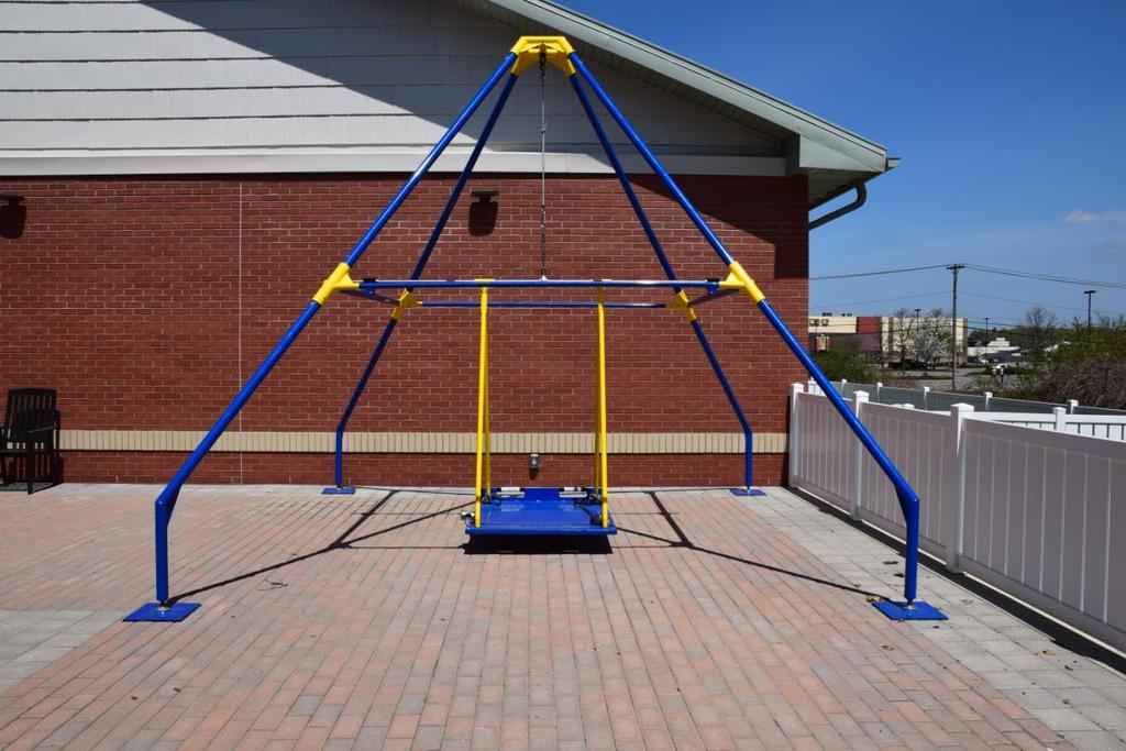
Document Revision No.: 0 Revised: 05/11/2015 RIT KGCOE MSD Program DUAL PURPOSE WHEELCHAIR-PLATFORM SWING ASSEMBLY MANUAL
|
|
|
- Jerome Wilson
- 5 years ago
- Views:
Transcription
1 DUAL PURPOSE WHEELCHAIR-PLATFORM SWING ASSEMBLY MANUAL


2 DUAL PURPOSE WHEELCHAIR-PLATFORM SWING FRAME ASSEMBLY STEP 1 (Video Reference: STEP 1_SQTUBE-BWELD SUBASSY) Assemble square tube-bottom weldment subassemblies XY and WZ. Clear any debris from the inside of the weldment and the outside of the square tubing using soft rag. If there are problematic areas, a light sanding may be used followed by the clearing of debris by a soft rag. (Only sand if completely necessary for assembly). Slip the X end of the XY square tube into the X weldment. Slip the Y end of the XY square tube into the Y weldment. Do not pin. Slip the W end of the WZ square tube into the W weldment. Slip the Z end of the WZ square tube into the Z weldment. Do not pin. Set both subassemblies off to the side for future use lifting only by weldments to move.

. Have one person hold the bottom weldment in resting position.")
3 STEP 2 (Video Reference: STEP 2_PIPES-TWELD SUBASSY) Assemble Pipes I, II, III, IIII-top weldment subassembly. Gather the top weldment, four large pins and pipes X I, W II, Y IIII, Z III. Clear any debris from the inside of the weldment and the outside of legs on the sides labeled I- IIII using soft rag. If there are problematic areas, a light sanding may be used followed by the clearing of debris by a soft rag. (Only sand if completely necessary for assembly). Put the top weldment on the ground with the universal joint facing upwards (shown above). Have one person hold the bottom weldment in resting position. Align pipe X I in the weldment using the dotted lines and corresponding marks as your guide; slip I side of X I into place ensuring you maintain the proper angle the entire time. Have the second person secure with pin from the outside in. While bottom weldment is still secured in resting position. Align pipe Z III (the position located diagonally across the weldment) in the weldment using the dotted lines and corresponding marks as your guide; slip III side of Z III into place ensuring you maintain the proper angle the entire time. Have the second person secure with pin from the outside in. Repeat steps with Legs pipes Y IIII and W II one at a time, ensuring it is supported at all times. Make sure to insert pins from the outside after each leg is slipped into place


4 STEP 3 (Video Reference: STEP 3_XY SUBASSY-TWELD SUBASSY) Connect XY bottom weldment subassembly to top-weldment subassembly. Lean the top weldment subassembly structure so XY pipes are ground side. To assist in the next step of the assembly process, it may be helpful to prop the pipes up on 2 x 4 pieces of wood to ease alignment. Align the XY bottom weldment subassembly with the end of the corresponding pipes in top weldment sub assembly. Each assembler should take a side and together, insert the X and Y sides of pipes X I and Y IIII into their respective X and Y weldments. Because of the angles movement of the X and Y weldments to their correct positions on the pipes needs to be done together or at the very least in the same incremental amounts. (For example, if you move weldment X up a half an inch on pipe, you need to then move weldment Y up a half an inch on pipe before moving X up any further!) Nothing besides the top weldment pipes into the top weldment should be pinned. A rubber mallet may be used to help move the weldment to the correct position on the pipe shown by the white circular marking that goes all the way around the pipe.

5 STEP 4 (Video Reference: None) Rotate system and insert support pipes into XY. Lean the top weldment subassembly structure so WZ pipes are ground side. To assist in the next steps of the assembly process, it may be helpful to prop the pipes up on 2 x 4 pieces of wood to ease alignment. Insert the small support pipes upwards into their respective X and Y weldments that are now in the air.

6 STEP 5 (Video Reference: STEP 5_WZ SUBASSY-TWELD SUBASSY) Connect WZ bottom weldment subassembly to top-weldment subassembly. Align the WZ bottom weldment subassembly with the end of the corresponding pipes in top weldment sub assembly. Each assembler should take a side and together, insert the W and Z sides of pipes W II and Z III and the support pipes into their respective W and Z weldments. This is tricky because you are just slightly trying to get four pipes started at the same time. You may need an extra person on each side to help with this process. You want to get everything just started. At this point, you may want to also ensure that the square tubing is equally as far in on each of the weldments for WZ. Often if it is very far in on one weldment, but slipped out very far on the other weldment, you will have trouble. Remember that because of the angles movement of the W and Z weldments up the pipes need to be done together or at the very least in the same incremental amounts. Do not put weldments into their final locations on the pipes. Nothing besides the top weldment pipes into the top weldment should be pinned.


7 STEP 6 (Video Reference: STEP 6_TEEPEE) Flip system to rest on bottom four weldments (Tee-Pee) Using only the weldments apply pressure and flip entire structure over (like a tee-pee) so it rests on the four bottom weldments. Pin in the WZ square tube into the weldments. (A mallet may be needed to ensure that the white line on the square tubing appropriately lines up with the weldment edge. Additionally, lifting weldments one at a time may reduce the stress on the square tubing making pinning easier.) Pin in the XY square tube into the weldments. (A mallet may be needed to ensure that the white line on the square tubing appropriately lines up with the weldment edge. Additionally, lifting weldments one at a time may reduce the stress on the square tubing making pinning easier.) Attach the cable and turnbuckle piece to the universal joint while it is at this height. (It will save you from having to get a ladder.)

8 STEP 7(Video Reference: STEP 7_BWELD-BPIPES) Insert bottom pipes with footers Gather the bottom pipes with footers and lay the corresponding pipe near its bottom weldment. Using the WZ bottom weldments or the center of the WZ square tube, lift the structure upwards. Slide bottom leg W into bottom weldment W by lining up the dotted lines. (Ensure that you are inserting at the correct angle. Twisting the leg as you slide into bottom weldment W may help the process.) Pin pipe into weldment. Slide bottom leg Z into bottom weldment Z by lining up the dotted lines. (Ensure that you are inserting at the correct angle. Twisting the leg as you slide into bottom weldment Z may help the process.) Pin pipe into weldment. Using the XY bottom weldments or the center of the XY square tube, lift the structure upwards. Slide bottom leg X into bottom weldment X by lining up the dotted lines. (Ensure that you are inserting at the correct angle. Twisting the leg as you slide into bottom weldment X may help the process.) Pin pipe into weldment. Slide bottom leg Y into bottom weldment Y by lining up the dotted lines. (Ensure that you are inserting at the correct angle. Twisting the leg as you slide into bottom weldment Y may help the process.) Pin pipe into weldment. It is ok to use a mallet if you are having trouble getting the pin through. Just ensure proper alignment before you use mallet.

9

10 DUAL PURPOSE WHEELCHAIR-PLATFORM SWING ATTACHING PLATFORM SWING STEP 1 (Video Reference: None) Clip on swing to turn buckle piece. Twist in the regular eye bolt. Once eye bolt is secure, clip on platform swing.
11 DUAL PURPOSE WHEELCHAIR-PLATFORM SWING ATTACHING WHEELCHAIR SWING STEP 1 (Video Reference: None) Remove eye bolt. Ensure swing does not have the eye bolt attached to the turn buckle. If it does twist this piece out of the turn buckle.

12 STEP 2 (Video Reference: STEP 2_SHAFT) Secure pillow block bearings to mounts. Have each person grab one side of the shaft. The pillow blocks housing the bearing should already be in place as they have clamps that should not be removed. Align the pillow block bearing screw holes with the threaded holes in the mounts on the square tubes. Secure each side with four screws using an allen wrench to tighten.


13 STEP 3 (Video Reference: None) Install rod end bearing for center support. Now that the shaft is secured, take the already attached bearing in the center of the shaft and rotate it upwards towards the turnbuckle and cable. Insert the end of the bearing into the turn buckle piece and begin to tighten. Tighten so it is taut. Move the platform underneath the shaft.

. Tighten the nuts to the bolts that are now poking through on the bottomside of the platform.")
14 STEP 4 (Video Reference: None) Attach swing to frame attachment to platform. Place platform on a surface that raises it up a few inches off of the ground but does not cover the corners. Take the swing to frame attachment piece labeled with a triangle and insert the bottom two threaded rods into the platform. Repeat with the piece labeled with a square. (Depending on the direction you want the swing, you will need to plan acordingly to ensure that you line up correctly with the corresponding shapes on the shaft female pieces that will receive the swing to frame attachments). Tighten the nuts to the bolts that are now poking through on the bottomside of the platform. Hand tight is sufficient for immediate use but it is reccommended that you inspect often and tighten with wrench. This portion is easiest with four people. Lineup the square labels and the triangle labels. Now that the STFA is attached to the platform the top male pieces of the swing to frame attachment need to be slid into the female pieces hanging off the shaft. With two people lifting slowly, have the other two people guide the male piece into the female piece for each side. Secure with short pins.
15
For additional assistance call
 The following pages will help guide you through the process of assembling your new 48 custom prize wheel. Choose an assembly area with plenty of room to lay your pieces on the floor and also a bench or
Sit Down Table Assembly Instructions
 Sit Down Table Assembly Instructions Parts that come with your sit down table A B C D E F G H I J K L M N Extension leaf Table with cutout for machine Two table legs One table leg with long support One
Installation Instructions for the AlphaDeck Staging System
 Installation Instructions for the AlphaDeck Staging System Step 1 - Preparation A. Before setting up your system, determine the location where the stage will be installed and locate all the parts you will
This manual will aid in the assembly of the FireBall V90 and FireBall X90. The assembly of both machines will be identical, unless specified.
 This manual will aid in the assembly of the FireBall V90 and FireBall X90. The assembly of both machines will be identical, unless specified. Step #1 Lay all parts out to verify quantities. (2) 2 x 25-1/4
INSPECTION AND CORRECTION OF BELLHOUSING TO CRANKSHAFT ALIGNMENT
 INSPECTION AND CORRECTION OF BELLHOUSING TO CRANKSHAFT ALIGNMENT BACKGROUND Proper alignment of the transmission input shaft to the crankshaft centerline is required in order to achieve the best results
Sheet Metal Brake Plans for a 6' Sheet Metal Brake
 Sheet Metal Brake Plans for a 6' Sheet Metal Brake,1752'8&7,21 Thank you for purchasing the sheet metal brake plans. The plans include a complete list of material needed and easy to follow steps to build
mila-wall (Series100) General Operating Instructions page 1 of 15
 General Operating Instructions page 1 of 15") mila-wall (Series100) General Operating Instructions page 1 of 15 Step #1: Before setting up walls, lower adjustable leveling feet on each panel approximately 1". This will allow access to the threaded
mila-wall (Series100) General Operating Instructions page 1 of 15 Step #1: Before setting up walls, lower adjustable leveling feet on each panel approximately 1". This will allow access to the threaded
BABY WOLF LOOM. Assembly Instructions for Knocked-Down Looms
 BABY WOLF LOOM Assembly Instructions for Knocked-Down Looms BEFORE YOU BEGIN Please read through the directions before beginning to assemble your loom. Unpack the loom parts carefully. Do not throw away
Replacing the Reciprocator on the SWF Compact Series Machine (601C and 1201C)
") Follow the instructions below to replace the reciprocator in the SWF Compact series machines. The tools required can be found in the tool kit that came with the machine. Preparation 1. First, place the
Follow the instructions below to replace the reciprocator in the SWF Compact series machines. The tools required can be found in the tool kit that came with the machine. Preparation 1. First, place the
Drake Off Road Hood Hold Downs Installation Guide
 Installation Time: 30 Minutes Tools Required: Drake Off Road Hood Hold Downs Installation Guide 3/8 drive ratchet 13mm socket 10mm socket (deep-well socket helpful) 13mm wrench (2x) 4mm allen wrench 5mm
Mount to the Wall INSTALLATION MANUAL
 Mount to the Wall 15 Locate the Wooden Studs This step applies to wooden stud wall installation only. Determine and mark the exact locations of two stud centers on the wall. Wooden studs should be spaced
PPFE 12 Miter Disk Sander
 PPFE 12 Miter Disk Sander Instructional Manual 1 2017 framingsupplies.com Parts 1. Base 2. Sanding Wheel 3. Guide 4. Guide Axle 5. Guide Handle 6. Bearing Assembly 7. Triangle 2 3 6 7 4 1 5 Set-Up Instructions
BBF Series Blower Base Frame Assembly Instructions Rev.: BFA-9105
 BBF Series Blower Base Frame Assembly Instructions Rev.: BFA-9105 These assembly instructions are to be used as a general reference guide to facilitate assembly. Please consult the blower, bushing, sheave,
HANDLING AND ASSEMBLY INSTRUCTIONS FOR TRUE FOCUS 3.0M, 3.8M AND 4.2M ANTENNAS WITH POLAR MOUNT
 HANDLING AND ASSEMBLY INSTRUCTIONS FOR TRUE FOCUS 3.0M, 3.8M AND 4.2M ANTENNAS WITH POLAR MOUNT Introduction SECTION 1 Thank you for purchasing one of our fine True Focus products. This manual covers the
TABLE OF CONTENTS REQUIRED TOOLS
 TABLE OF CONTENTS SECTION SECTION TITLE PAGE NO. 1 2 3 4 5 Assembling Mounting Structure Installing Bicycle Supports Mounting Rack to Wall Adding Sections Customizing Rack Configuration REQUIRED TOOLS
INVENT3D Printer Kit Disassembly Instructions
 INVENT3D Printer Kit Disassembly Instructions Version 6 AST2 10/26/16 1 I. General Disassembly Instructions Use the case layer drawings to ensure that components are stored in the appropriate location
Anti-Chattering Retrofit Assembly
 Anti-Chattering Retrofit Assembly Please follow through these instructions carefully and thoroughly. If you have questions, feel free to contact a Bend-Tech service representative at our office 651-257-8715
SCHACHT STANDARD FLOOR LOOMTM
 SCHACHT STANDARD FLOOR LOOMTM FL3109 FL3111 FL3113 FL3115 FL3121 FL3123 FL3125 FL3127 FL3310 FL3312 FL3314 FL3316 FL3322 FL3324 FL3326 FL3328 Assembly instructions LOW CASTLE LOOM IN MAPLE Find out more
======================================================================================== ( DR / DR) JK WRANGLER MOD RACK
 JK WRANGLER MOD RACK") (10984 4DR / 10982 2DR) JK WRANGLER MOD RACK INSTALLATION SHEET Important Notes: Some brands of windshield light brackets and snorkels may not be compatible with the 10984 MOD Rack System. Body lifts are
(10984 4DR / 10982 2DR) JK WRANGLER MOD RACK INSTALLATION SHEET Important Notes: Some brands of windshield light brackets and snorkels may not be compatible with the 10984 MOD Rack System. Body lifts are
BOW-A-CONSTRICTOR BUCKEYE ARCHERY SOLUTIONS
 BOW-A-CONSTRICTOR BUCKEYE ARCHERY SOLUTIONS User Guide: Bow-A-Constrictor Tuning Station Note: The following instructions begin with the power bar tongue set at approximately the 6th hole from the crank.
TRAILMATE METEOR ASSEMBLY MANUAL
 TRAILMATE METEOR ASSEMBLY MANUAL The Trailmate Meteor recumbent has been designed for easy assembly. This means more time to enjoy the smooth ride with single speed, 3 speed coaster brake and 21 speed
ASSEMBLY INSTRUCTIONS JK270
 TOOLS REQUIRED: One knife to open packaging Two ½ wrench or socket (metric 13) One 9/16 wrench or socket (metric 14) One #2 Philips (+) screwdriver NOTE: All bolts are 9/16 (metric 14) and nuts are ½ (metric
Baby Grande or Grande Crank Shade with Cables and Housing Installation Instructions
 Baby Grande or Grande Crank Shade with Cables and Housing Installation Instructions Tools Needed Drill 3/8 Metal Drill Bit Screwdriver (Flat & Phillips) Measuring Tape Pencil 4 Level Plumb Line ¼ Masonry
Kai Installation Instructions
 Kai Installation Instructions Before Beginning Installation Read through the entire instruction thoroughly A minimum of 2 people are required for this assembly These instructions reflect typical assemblies;
The Bowflex Revolution XP Home Gym Assembly Instructions. P/N: Rev ( /0 )
") P/N: 001-7057 Rev ( /0 ) The Bowflex Revolution XP Home Gym Assembly Instructions 2 Table of Contents Before You Start... 2 Tools You Will Need / Hardware Contents... 3 Box Contents... 6 Assembling Your
P/N: 001-7057 Rev ( /0 ) The Bowflex Revolution XP Home Gym Assembly Instructions 2 Table of Contents Before You Start... 2 Tools You Will Need / Hardware Contents... 3 Box Contents... 6 Assembling Your
M2 Assembly. M2 Sub-Assemblies mm Belt Sub-Assembly mm Belt Sub-Assembly Spider Sub-Assembly... 4
 M2 Assembly Table of Contents M2 Sub-Assemblies... 3 630mm Belt Sub-Assembly... 3 702mm Belt Sub-Assembly... 3 Spider Sub-Assembly... 4 Idler Bolt Sub-Assembly... 8 Y Motor Sub-Assembly... 9 X Motor Sub-Assembly...
TOOLS REQUIRED: HARDWARE INCLUDED: 13MM FLAT WRENCH FOR LEVELING THE STRUCTURE RATCHET WITH 5MM HEX BIT FOR CORNER SCREWS ON TOP TRAVERSE BEAMS
 1 TOOLS REQUIRED: RATCHET WITH 5MM HEX BIT FOR CORNER SCREWS ON TOP TRAVERSE BEAMS 13MM FLAT WRENCH FOR LEVELING THE STRUCTURE RUBBER MALLET FOR INSERTING PANELS 8MM HEX BIT WITH EXTENSION FOR HEX BOLT
EMO. Service Instruction. created by Frank Weithöner. Table of contents: Special Tools Assembling Mixing Chamber
 EMO Service Instruction created by Frank Weithöner Table of contents: - Special Tools Disassembling Mixing Chamber Assembling Mixing Chamber Adjustment Rotor / Level Indicator Unit Temperature Compensating
What you should have. 1. Telescopic Pole (1) 2. Arc tubing (4) for Lower Ring. 3. Numbered bars or spokes(8) 4. Center plate (1)
 2. Arc tubing (4) for Lower Ring. 3. Numbered bars or spokes(8) 4. Center plate (1)") 20 ft RGB Pole Tree What you should have 1. Telescopic Pole (1) 2. Arc tubing (4) for Lower Ring 3. Numbered bars or spokes(8) 4. Center plate (1) 5. Top Ring (1) 6. Hardware and wrenchs a. Hardware i.
20 ft RGB Pole Tree What you should have 1. Telescopic Pole (1) 2. Arc tubing (4) for Lower Ring 3. Numbered bars or spokes(8) 4. Center plate (1) 5. Top Ring (1) 6. Hardware and wrenchs a. Hardware i.
Playground Assembly Instructions
 Before You Begin Playground Assembly Instructions Locate the playground set on firm, level ground. Assemble the playground on or close to its permanent location Two people are recommended to assemble the
The Derby Magic Company Track Assembly Instructions, revision D page 1 of 10
 The Derby Magic Company Track Assembly Instructions, revision D page 1 of 10 Thank you for purchasing a Derby Magic Pinewood Derby Track. To assemble your track, start with the stand. The parts of the
Baby Grande or Grande Crank Shade with Cables and Housing Installation Instructions
 Baby Grande or Grande Crank Shade with Cables and Housing Installation Instructions Tools Needed Drill 3/8 Metal Drill Bit Screwdriver (Flat & Phillips) Measuring Tape Pencil 4 Level Plumb Line ¼ Masonry
13MM FLAT WRENCH FOR LEVELING THE GLIDES OF STRUCTURE 6MM ALLEN KEY FOR ROOF CLIPS PHILLIPS HEAD BIT FOR SCREWS FOR DOOR FRAME
 1 TOOLS REQUIRED: MOVING CART/DOLLY FOR TRANSPORTING PANELS, ROOF, AND POSTS TWO 9 FT. STEP LADDERS FOR INSTALLING ROOF & PANELS REVERSIBLE RATCHET 1/4 DRIVE FOR CORNER SCREWS ON TOP TRAVERSE BEAMS ALTERNATIVE
PFT CABLE GYM INSTRUCTION MANUAL
 PFT CABLE GYM INSTRUCTION MANUAL QUESTION? As a quality home gym supplier we are committed to your complete satisfaction. If you have questions, or find missing or damaged parts, we will guarantee your
Therma-Tru Door Gallery Setup Instructions Swing Unit with Hardware Kit - Hardware Part # MADGSWU15 (Swing Unit) Part # MADGHKSU10 (Hardware Kit)
 Part # MADGHKSU10 (Hardware Kit)") Swing Unit with Hardware Kit - Hardware Tools Included: 4mm Allen Wrench, 6mm Allen Wrench, 8mm T-Handle Allen Wrench (1) 3/4" Drill Bit, (1) 7/32" Drill Bit and Hole Template Guide Tools Required: Phillips
Swing Unit with Hardware Kit - Hardware Tools Included: 4mm Allen Wrench, 6mm Allen Wrench, 8mm T-Handle Allen Wrench (1) 3/4" Drill Bit, (1) 7/32" Drill Bit and Hole Template Guide Tools Required: Phillips
Pvcu Bi Folding Doors Fitting Instructions.
 Pvcu Bi Folding Doors Fitting Instructions. THE FOLLOWING INSTRUCTIONS ARE GIVEN IN GOOD FAITH AND ARE FOR GUIDANCE ONLY. NO RESPONSIBILITY WILL BE ACCEPTED FOR ANY MIS- INTERPRETATION. WHEN INSTALLING
Cutless Bearing Removal and Replacement for a Watkins 27 By John Everson
 Cutless Bearing Removal and Replacement for a Watkins 27 By John Everson This is a fairly difficult job, but if you are mechanically inclined and want to save a significant amount of cash, you might want
ClearSpan PolyMax Windbreak Wall
 ClearSpan PolyMax Windbreak Wall Photo may show a different but similar model. 2007 ClearSpan All Rights Reserved. Reproduction is prohibited without permission. Revision date: February 2007ldg STK# DIMENSIONS
PEARL DRUM PEDAL. Instruction Manual
 PEARL DRUM PEDAL Instruction Manual Congratulations on your purchase! To get optimum performance of your "P-3002D" Drum Pedal, please read this Instruction Manual before playing. Drive Shaft Assembly Drive
Technicians of Terror. This is the air valve we make to use with our air
 These are pictures of our scissor prop. Technicians of Terror http://www.halloweenfear.com/scissorprop.html props. This is the air valve we make to use with our air This pictures the duel door closer cylinders
a.k.a. casegoods instructions
 a.k.a. casegoods instructions a a.k.a. workwall installation IMPORTANT NOTES Failure to install product according to installation instruction will result in loss of warranty. Tools required for assembly
Hatchback Wing Riser Kit
 Hatchback Wing Riser Kit 2015-06-11 Thank you for purchasing this PERRIN product for your car! Installation of this product should only be performed by persons experienced with installation of aftermarket
Side Winder R o u t e r L i f t.
 Woodpeckers PRECISION WOODWORKING TOOLS Side Winder R o u t e r L i f t. INSTALLATION INSTRUCTIONS The wrench handle must be pointing left in order to fully insert or remove it. Lift Wrench Once fully
MM750 Installation Instructions
 MM750 Installation Instructions IMPORTANT SAFETY INSTRUCTIONS - SAVE THESE INSTRUCTIONS Please read this entire manual before you begin. Do not unpack any contents until you verify all requirements on
Assembly Instructions: Bencher Skylark
 Assembly Instructions: Bencher Skylark Tools Required: Pop Rivet Tool Tape Measure Hex Wrenches Screwdriver Several Disposable Rags Two Saw Horses Several boxes or bowls to hold fasteners and small parts
Installing the 3 Indexer: PRS Standard Tools
 888-680-4466 ShopBotTools.com Installing the 3 Indexer: PRS Standard Tools Copyright 2016 ShopBot Tools, Inc. page 1 Copyright 2016 ShopBot Tools, Inc. page 2 Table of Contents Route Cable into Box...5
Sunrise Deck Assembly Instructions for Kingston Left
 Sunrise Deck Assembly Instructions for Kingston Left It s easiest to build the deck frame first like it will be lying on its back and then after all 4 legs and horizontals are in place, tip the deck toward
Large Wood Windmill Assembly Instructions
 CROW S NEST (TOP VIEW) TOWER (SIDE VIEW) 0 QTY 2 2 ITEM QTY 2 QTY QTY 8 QTY 8 QTY 4 TOP TOP TOP 47 9 QTY 4 QTY 4 QTY 4 QTY 4 QTY 4 ITEM 6 ITEM 7 ITEM 8 ITEM 3 ITEM 9 ITEM 4 ITEM 2 ITEM 5 47 Leg QTY 4 42.5
Strata. urniture. Adriana Instructions. Parts in the Arm Box: Parts in the Body Box: Watch our assembly videos at
 1A Watch our assembly videos at www.strataf.com/videos Parts in the Arm Box: Arm - Outside View Arm - Inside View 1B Parts in the Body Box: Back Deck x 1 Seat Deck x 1 with the Feet attached Back Panel
9 X 9 REMOVABLE TYPE ALUMINUM WINDOW BARS INSTALLATION INSTRUCTIONS Import Note : 9 X 9 Spacing Removable Type Installation is covered in this
 Import Note : 9 X 9 Spacing Removable Type Installation is covered in this Instruction. Removable Bars Only Mount in Recess Position ( Between Window Jamb/ Frame ) The spacing between horizontal bars is
The Derby Magic Company Track Assembly Instructions, revision F page 1 of 13
 The Derby Magic Company Track Assembly Instructions, revision F page 1 of 13 Thank you for purchasing a Derby Magic Pinewood Derby Track. To assemble your track, start with the stand. The parts of the
Lumber Smith. Assembly Manual. If you are having problems assembling the saw and need assistance, please contact us at:
 Lumber Smith Assembly Manual If you are having problems assembling the saw and need assistance, please contact us at: 804-577-7398 info@lumbersmith.com 1 Step 1 Safety Carefully read the Owners Manual.
Hardware and Components:
 Hardware and Components: (A) 4X 5/16 x 1 Carriage Bolt (B) 2X 5/16 x 2-1/4 Carriage Bolt (C) 2X 5/16 x 3-1/4 Hex Bolt (D) 2X 5/16 x 3/4 Hex Bolt (E) 2X 5/16 x 1-1/4 Hex Bolt (F) 5/16 x 2-1/4 Hex Bolt (G)
3. X-axis assembly. 3. X-axis assembly. Written By: Jakub Dolezal manual.prusa3d.com/ Page 1 of 13
 3. X-axis assembly Written By: Jakub Dolezal 2018 manual.prusa3d.com/ Page 1 of 13 Step 1 Tools necessary for this chapter Needle-nose pliers for zip tie trimming. 2.5mm Allen key for M3 screws 2mm Allen
TRAMPOLINE A SSEMBLY I N S T RUC T I ONS
 OVAL TRAMPOLINE A SSEMBLY I N S T RUC T I ONS Safety Tips At Oz Trampolines, we are passionate about your family s safety when using our trampolines and accessories. We have put together a list of safety
VSD-6500 Frame Exploded View LIFT P/N
 VSD-6500 Frame Exploded View LIFT P/N 511-65075-01 34 34 45 96 55 108 22 9 7 55 54 34 89 90 56 24 99 23 111 SEE SHEET 4 34 91 45 106 20 55 26 68 95 5 55 109 7 22 8 54 53 71 66 5 95 31 58 6 6 46 60 73 25
Series Assembly Instructions
 ComforTrak TM Series Assembly Instructions EP-560, EP-860, EP-960 & EP-970 Models *Inversion Table images may vary slightly from your model. The EP-560 is shown here. BEFORE YOU BEGIN: Review all steps
Instructions to fit Emulator in place of floppy drive M.D.R.
 Instructions to fit Emulator in place of floppy drive M.D.R. Before starting, read through all the following instructions, and then when you do begin, read each number section before attempting that particular
400A 40113V, 401A 40120V, & 401AL 40120VL ALUMINUM VERTICAL 4000 LB LIFT INCLUDES SCREW LEG ASSEMBLY INSTRUCTIONS
 12/11/07 PAGE 1 OF 12 400A 40113V, 401A 40120V, & 401AL 40120VL ALUMINUM VERTICAL 4000 LB LIFT INCLUDES SCREW LEG ASSEMBLY INSTRUCTIONS Thank you for purchasing our product! *Please read these instructions
MODEL 200/220 ASSEMBLY INSTRUCTIONS
 V-Twin MFG. Coats Tire Changer VT Part No. 16-0510 This tool should only be used by a knowledgeable and trained motorcycle technician V-Twin Mfg. accepts no responsibility for improper use. MODEL 200/220
Read Below! Read Below! Read Below! Read Below! Read Below! Read Below! STOP READ TIPS BELOW TO MAKE ASSEMBLY MUCH EASIER
 Read Below! Read Below! Read Below! Read Below! Read Below! Read Below! STOP READ TIPS BELOW TO MAKE ASSEMBLY MUCH EASIER Here are some guidelines to help make assembling your unit much easier: -Read and
Bend-Tech Dragon Assembly Manual
 p.1 Bend-Tech Dragon Assembly Manual IMPORTANT: Please read before unpacking. Place shipping container in a wide open area where you will have room to work and assemble this product. Shipping The Dragon
ENGINEERING STRENGTH INSTAL L AT I O N M A NUAL OUR STRENGTH IS OUR STRENGTH
 ENGINEERING STRENGTH INSTAL L AT I O N M A NUAL OUR STRENGTH IS OUR STRENGTH RAFTER PREPERATION RAFTER PREPARATION A FRAME PREPERATION AND ASSEMBLY A FRAME PREPARATION AND ASSEMBLY... Open boxes, remove
Adjusting, Changing and Maintaining The Latches and Catches on Your Airstream
 Adjusting, Changing and Maintaining The Latches and Catches on Your Airstream Hinges,Latches and Catches in your Airstream Bumps, pulling, gravity and time can have an affect on hinges and latches. Adjustments
The Derby Magic Company Track Assembly Instructions, revision E page 1 of 12
 The Derby Magic Company Track Assembly Instructions, revision E page 1 of 12 Thank you for purchasing a Derby Magic Pinewood Derby Track. To assemble your track, start with the stand. The parts of the
Queen Wingback Bed King Wingback Bed
 Parts and Hardware List A. Side Rails with Attachment Hooks 2 pcs B. Foot Rail 1 pc C. Head Rail 1 pc D. Center Support Slat 1 pc E. Leg Supports 3 pcs F. Support Slats 4 pcs G. Flat Washers 8 pcs H. Lock
Rotary Fixture M/V/X CLASS LASER SYSTEMS. Installation and Operation Instructions
 Rotary Fixture M/V/X CLASS LASER SYSTEMS Installation and Operation Instructions 02/01/2000 Introduction The Rotary Fixture controls in the Printer Driver are used along with the optional Rotary Fixture
OWNERS MANUAL MODEL F660 HIP SLED
 OWNERS MANUAL MODEL F HIP SLED QUESTION? As a quality home gym supplier we are committed to your complete satisfaction. If you have questions, or find missing or damaged parts, we will guarantee your complete
IMPORTANT!!! ASSEMBLY ASSEMBLY INSTRUCTIONS. (Internal Dimensions)
") ASSEMBLY ASSEMBLY INSTRUCTIONS (Internal Dimensions) Ent Spec Edition Ltr v-0- Overall dimensions including base: 7. L x 9 W x 0 H cms 97.5" L x 7" W x 8.7" H IMPORTANT!!! Please read these instructions
ASSEMBLY ASSEMBLY INSTRUCTIONS (Internal Dimensions) Ent Spec Edition Ltr v-0- Overall dimensions including base: 7. L x 9 W x 0 H cms 97.5" L x 7" W x 8.7" H IMPORTANT!!! Please read these instructions
High Rise Sit-Stand Desk Converter
 High Rise Sit-Stand Desk Converter Assembly Instructions for Model DC350 Patent No. 9,332,839 PRE-ASSEMBLY Please read all instructions before beginning assembly. We strongly recommend you watch the video
BIFOLD FUTON FRAME TRINITY ARM. Seat Rails and Slats x 1. *Note: Use 4pc of 100mm Bolts and 4pc of 60mm Bolts to attach the arms to the Stretchers.
 1A Parts in this box. 2pc with extra holes 2pc with extra holes & plastic stoppers Arms x 2 Back Rails and Slats x 1 Full Size: Slat Supports x 6 3pc are longer for the Back deck Back Side Rails x 2 Seat
Clearview Railing System Installation Instructions
 Clearview Railing System Installation Instructions Disclaimer: AGS Stainless, Inc. has its Clearview Railing Systems designed by a professional engineer to meet the requirements of the latest national
MOTORIZED STANDARD SHADE WITH CABLES Installation Instructions
 Tools Needed Drill Measuring Tape Pencil 2 Level Plumb Line ¼ Masonry Drill Bit Hammer Linesmans Pliers Cable Cutters Phillips & Flat-Head Screw Driver 11/32 Socket or Open End Wrench 5/32 Allen Wrench
TK 422 PORTABLE BRAKE
 1 TIN KNOCKER TK 422 PORTABLE BRAKE INSTRUCTIONS & PARTS DIAGRAM TAAG MACHINERY CO. (Master Distributor) 1257-B Activity Dr. Vista, Ca 92081 Tel: (800) 640-0746 Fax: (760) 727-9948 Website: www.tinknocker.com
Work Space Set-up. Slats will level the pipe during bending and help minimize twisting of the bow.
 Work Space Set-up Affix pipe bender to end of working surface Slats will level the pipe during bending and help minimize twisting of the bow. Make the slat height equal the distance from your work surface
Required Tools: Suggested Additional Tools: 1 Cordless Drill with Robertson Bits 1 Ratchet Wrench 1 7/16 or 11mm socket 1 7/16 or 11mm Gear Wrench
 Thank you for your recent purchase of a Cabinets by Hayley garage cabinet system. You are about to experience the best made cabinets that you can purchase. Cabinets by Hayley are designed for beauty and
Installation Guide: Oval Trampoline
 Trampolines & trampoline parts designed to survive in the harsh Oz climate. www.oztrampolines.com.au Installation Guide: Oval Trampoline Safety Tips Here at Oz Trampolines we are passionate about your
EDGE2 DUAL MONITOR ARM
 EDGE2 DUAL MONITOR ARM EDGE2 Rev A 2/17 Model EDGE2-SLV Model EDGE2-BLK Model EDGE2-WHT ASSEMBLY AND ADJUSTMENT EDGE2 DUAL MONITOR ARM PARTS AND TOOLS PLEASE REVIEW these instructions before beginning
INSTALLATION INSTRUCTIONS DODGE RAM 2 & 4WD 1500 PART # P5058
 INSTALLATION INSTRUCTIONS 2009-13 DODGE RAM 2 & 4WD 1500 PART # P5058 PARTS LIST: Qty Description Qty Description 1 Grille Guard 12 12-1.75mm Hex Nuts 2 Upper Frame Mounting s (for trucks without tow hooks
INS T A L L A TIO N INS T R U C TIO N S. Ceiling Mount Track System
 Ceiling Mount Track System 10.26.2016 Specifications Ceiling Post: Unassembled 2-7/8 Assembled 1-11/16 7/8 7-9/16 5-7/8 3/8 2 Tubes 1/2 2-3/8 5 Parts and Tools Tools Needed Tape Measure Pencil Drill with
RANGE DIGITAL HANDSET OPERATION. 1. Panel. 2. Initialization Procedure. 3. Move Up & Down. 4. Set Memory Positions. 5. Move to the Memorized Positions
 INSTRUCTION SHEET #2577INS PART #1730534 DIGITAL HANDSET OPERATION OPERATION INSTRUCTIONS 1. Panel 1 Button: Preset 1 2 Button: Preset 2 3 Button: Preset 3 S Button: Select Display: Reads in 1 / 2 " Increments
Read Below! Read Below! Read Below! Read Below! Read Below! Read Below! STOP READ TIPS BELOW TO MAKE ASSEMBLY MUCH EASIER
 Read Below! Read Below! Read Below! Read Below! Read Below! Read Below! STOP READ TIPS BELOW TO MAKE ASSEMBLY MUCH EASIER Here are some guidelines to help make assembling your unit much easier: -Read and
INSTALLATION INSTRUCTIONS for the JOMY RETRACTABLE LADDER. If there are any questions, please call (800)
") INSTALLATION INSTRUCTIONS for the JOMY RETRACTABLE LADDER If there are any questions, please call (800) 255-2591 INSTALLATION INSTRUCTIONS WARNING! Ladder Sections Lock When Closed. Do Not Install or Close
INSTALLATION INSTRUCTIONS for the JOMY RETRACTABLE LADDER If there are any questions, please call (800) 255-2591 INSTALLATION INSTRUCTIONS WARNING! Ladder Sections Lock When Closed. Do Not Install or Close
Assembly Instructions 10 X 10 Aluminum Frame Building
 Assembly Instructions 10 X 10 Aluminum Frame Building 27 97 9 8 47 36 74 52 10 10 X 10 Square Building W/ Dome Includes: The Steel Entry Door with a Dead Bolt Lock assembly and Aluminum Door Frame. Metal
Vinyl Gazebo Instructions
 P a g e 1 Vinyl Gazebo Instructions 10 Vinyl Gazebo Shown Thank you for the purchase of your New Gazebo. Depending on the size of your Gazebo, installation can usually be completed in 1 to 2 days. These
Precision Steel Car s 100 T Steel Coil Car
 Precision Steel Car s 100 T Steel Coil Car Precision Steel Car www.precisionsteelcar.com info@precisionsteelcar.com Paul Vernon: (513) 571-5739 Revised 4/30/2009 Contents of Kit Main Tube Side Frame 2
ClearSpan End Frame Kit 26' Wide x 12' High
 ClearSpan End Frame Kit 26' Wide x 12' High Diagram shows the end frame kit for an end wall without a door. (Door and end panel are purchased separately.) Rafter and struts shown in the above diagram are
Mechanical Frappe Press
 Mechanical Frappe Press Operation Manual CONTENTS OPERATIONAL INSTRUCTIONS PRECAUTIONS PART NAMES INCLUDED ITEMS BASIC OPERATION MAINTENANCE REPLACEMENT PARTS Thank you for using The Frapptastic Five Mechanical
Diva Acoustical Ceiling
 Installation Instructions Diva Acoustical Ceiling CONTENTS Important User Information...........................2 Safety Precautions.................................3 Required Tools....................................3
i f c o L INC. COMPLETE MOTORIZED GLIDE OUT ADJUSTMENTS PROCEDURE MANUAL #400011
 i f c o L INC. 24076 Reedy Dr. Elkhart, IN 46514 (574)-266-5551 (Office) (574)-206-9296 (Fax) COMPLETE MOTORIZED GLIDE OUT ADJUSTMENTS PROCEDURE MANUAL #400011 The following procedures are used to acquire
Tools Needed Hardware Provided (per shade) Hardware Needed
 Hardware Needed") Baby Grande or Grande Motorized (XQ5 Premium) Shade with Cables and Housing Installation Instructions Tools Needed Hardware Provided (per shade) Hardware Needed Drill 3/8 Metal Drill Bit Measuring Tape
Baby Grande or Grande Motorized (XQ5 Premium) Shade with Cables and Housing Installation Instructions Tools Needed Hardware Provided (per shade) Hardware Needed Drill 3/8 Metal Drill Bit Measuring Tape
Code Product Qty 1 Top Vertex 3 2 Hot End Housing 1 3 Bottom Vertex 3 4 Print Platform Lock 3 5 End Stop Holder 3 6 Filament Feeder Motor Bracket 1 7
 List of Parts Code Product Qty 1 680mm Extrusion 3 2 Power Supply 1 3 240mm Extrusion 9 4 42mm Nema 17 Stepper Motor 3 5 Slider-Hotend Connecting Rod 6 6 48mm Nema 17 Stepper Motor 1 7 Linear Rail with
TRUE TECHNICAL SERVICE MANUAL - ALL MODELS. DOORS/DRAWERS/LIDS
 DOORS/DRAWERS/LIDS 55 56 NOTES DOORS/DRAWERS/LIDS Springs 97 TORSION SPRING REPLACEMENT GDM RADIUS FRONT - SWING DOOR INSTALLATION INSTRUCTIONS Tools Required (2) - 1 8" drift Punch (forged) Needle-Nose
Assembly Instructions & General Overview
 Assembly Instructions & General Overview 1. General Overview & Assembly Order...Page 3 2. Assembling the Structural Components Page 4-11 3. Power, Data, Power Poles and Cable Floor Boxes.Page 12-17 4.
GlideRite Retractable Cover System For HotSpring & Tiger River Spas (except Classic & pre-2000 Landmark Spas)
") List of Contents Quantity Description 12 #10 x 1 ½ Flat Head Phillips Screw (see pg. 2) 2 #10 x ½ Pan Head Phillips Screw (see pg. 2) 8 ¼ x 2 ½ Lag Bolt (see pg. 2) 7 ¼ 20 x 5 / 8 Hex Head Bolt (see pg.
List of Contents Quantity Description 12 #10 x 1 ½ Flat Head Phillips Screw (see pg. 2) 2 #10 x ½ Pan Head Phillips Screw (see pg. 2) 8 ¼ x 2 ½ Lag Bolt (see pg. 2) 7 ¼ 20 x 5 / 8 Hex Head Bolt (see pg.
MantelMount. TM1A Installation Instructions IMPORTANT SAFETY INSTRUCTIONS - SAVE THESE INSTRUCTIONS
 MantelMount TMA Installation Instructions IMPORTANT SAFETY INSTRUCTIONS - SAVE THESE INSTRUCTIONS TM Thank you for choosing the MantelMount television wall mount. Please read this entire manual before
High Rise Adjustable Stand-Up Desk Converter
 High Rise Adjustable Stand-Up Desk Converter Assembly Instructions for Model DC200 Patent Pending PRE-ASSEMBLY Please read all instructions before beginning assembly. We strongly recommend you watch the
INSTRUCTION BOOKLET #34. For Wallbed models: KING SIZE SIERRA WITH STORAGE HEADBOARD
 For Wallbed models: KING SIZE SIERRA WITH STORAGE HEADBOARD INSTRUCTION BOOKLET #34 WARNING! ALL MURPHY/WALLBED SYSTEMS CONTAIN STORED ENERGY. FAILURE TO USE AND FOLLOW THESE INSTRUCTIONS DURING THE INSTALLATION
PEARL DRUM PEDAL. Instruction Manual
 PEARL DRUM PEDAL Instruction Manual Congratulations on your purchase! To get optimum performance of your "P-3002C" Double Pedal, please read this Instruction Manual before playing. Assembly Center Connecting
Installation Instructions
 The IMS ETERNAL FIX PATENT PENDING Installation Instructions EPS recommends professional installation for the Eternal IMS Fix. Please take all precautionary safety measures. We also recommend putting the