RadioProcessor-G. Owner s Manual. SpinCore Technologies, Inc.
|
|
|
- Kristopher James
- 5 years ago
- Views:
Transcription

1 Owner s Manual SpinCore Technologies, Inc.
2 Congratulations and thank you for choosing a design from SpinCore Technologies, Inc. We appreciate your business! At SpinCore we try to fully support the needs of our customers. If you are in need of assistance, please contact us and we will strive to provide the necessary support SpinCore Technologies, Inc. All rights reserved. SpinCore Technologies, Inc. reserves the right to make changes to the product(s) or information herein without notice. RadioProcessor-G, PulseBlaster, SpinCore, and the SpinCore Technologies, Inc. logos are trademarks of SpinCore Technologies, Inc. All other trademarks are the property of their respective owners. SpinCore Technologies, Inc. makes every effort to verify the correct operation of the equipment. This equipment version is not intended for use in a system in which the failure of a SpinCore device will threaten the safety of equipment or person(s)
3 Table of Contents I. Introduction... 5 Product Overview... 5 System Architecture...6 Example Application - MRI...7 Specifications... 9 II. Board Installation Installing the RadioProcessor-G...10 Testing the RadioProcessor-G...10 III. Creating Custom Pulse Programs Getting Started...11 Procedure for Writing a Pulse Program Step 1: Initialize MRI SpinAPI...11 Step 2: Define RF Output Parameters...11 Step 3: Data Acquisition Parameters...12 Step 4: Specify Parameters of the Pulse Sequence...13 Step 5: Trigger the Pulse Program Step 6: Retrieve Acquired Data...14 Useful References MRI SpinAPI Reference Manual...14 RadioProcessor Manual IV. Example Gradient Echo MRI Experiment...15 Tips on obtaining data using the gradient echo example...17 FID FID_Readout...17 V. Connecting to the RadioProcessor-G PCI RadioProcessor-G Board Connector Information BNC Connectors...18 SMA Connectors
4 Hardware Trigger/Reset Header (JP601)...20 Digital Output Header (JP600) Related Products and Accessories Contact Information Document Information
5 I. Introduction Product Overview The RadioProcessor Model G is an enhanced version of SpinCore's versatile RadioProcessor design. The RadioProcessor-G greatly expands upon the already extensive capabilities of the original RadioProcessor with the inclusion of three channels of user controlled gradient outputs. For more information on the general operation of the RadioProcessor, please refer to the RadioProcessor manual, which can be found on this webpage: The state-of-the-art design of the RadioProcessor-G allows it to serve as a complete system-on-chip solution for Magnetic Resonance Imaging (MRI), Nuclear Magnetic Resonance (NMR) applications in gradient enhanced spectroscopy and diffusion measurements, and Nuclear Quadrupole Resonance (NQR) experiments with spectrometer frequencies from 0 to 100 MHz (refer to the RadioProcessor manual for more details). The system integrates SpinCore s high-performance PulseBlaster timing engine for agile control of internal system components as well as TTL pulse/pattern generation for control of any external hardware. The RadioProcessor-G: Is a system-on-chip solution for MRI, NQR, and NMR applications, integrating excitation and acquisition components onto a single PCI card. Contains three analog output channels that allow for applications requiring pulses of varying amplitude and timing. Directly captures and digitally demodulates IF/RF signals. The desired baseband bandwidth is user definable through software. Generates completely formed RF excitation pulses as well as high resolution digital control signals. Maintains signal coherence between excitation and acquisition systems at all frequencies. Autonomously averages baseband signal data between multiple acquisitions. This unique digital system is housed on a small form factor PCI card, providing users with a compelling price/size/performance proposition unmatched by any other device on the market today
6 System Architecture Figure 1 presents the architecture of the RadioProcessor-G, which consists of four major components: the data acquisition core, the excitation core, the gradient control core, and the PulseBlaster timing engine, which provides highresolution timing control for the entire system. Incoming Signal ADC Digital Quadrature Detection Digital Filtering (user-customizable) Signal Averaging Internal RAM Acquisition core NCO Master clock RF Excitation signal DAC Phase and Frequency Registers, Gating Excitation core PulseBlasterTM Timing Core PCI Interface Host PC Digital Output Signals Analog Gradient Control Signals DAC Gradient DAC controller Gradient core RadioProcessor-G Figure 1: RadioProcessor Model G Architecture. The master clock oscillator signal is derived from an on-chip PLL circuit typically using a 50 MHz on-board reference clock. The acquisition core captures an incoming RF signal using a high-speed, high resolution Analog to Digital converter (ADC). This signal is then demodulated digitally using quadrature detection, and is then filtered to reduce the signal to baseband. The detection and filtering system is highly configurable and can easily be customized by the user for a wide variety of applications. The baseband signal can then be stored in an internal RAM. This data is then available to be retrieved by the host computer at the user's convenience. The excitation core can produce both RF Analog signals as well as digital outputs. The RF output is generated using an internal DDS (Direct Digital Synthesis) core, and can generate frequencies from DC up to 150 MHz. The generated signal is converted to the Analog output by an on-board digital-to-analog converter (DAC) This DDS core also drives the detection of the acquisition core, so signal coherence is maintained between acquisition and excitation cores. The gradient core controls three analog outputs that can be used to generate pulses with customizable durations and varying amplitudes of both positive and negative voltages. A standard application of the RadioProcessor-G uses these outputs to control the gradient coils for an MRI system, but they can also be used for gradient enhanced spectroscopy or diffusion applications. At the heart of the system is the PulseBlaster pulse/pattern generator timing core, which uses a robust instruction set designed to allow the creation of complex pulse sequences with ease. This timing core controls all aspects of the systems functionality, such as triggering data acquisition, controlling the frequency and gating RF output, etc. This core also controls the high resolution programmable digital outputs for controlling external hardware. Four digital outputs are available by default
7 Example Application - MRI A major application for the RadioProcessor Model G is Magnetic Resonance Imaging. Using the RadioProcessor Model G, a complete NMR/NQR system can be constructed with the addition of an RF power amplifier, a gradient amplifier, and a pre-amplifier. An example setup is shown below in Figure 2. Magnet Probe Gradient Coils X Y Z Rx Amplifier and Filter > Pre-amplifier (45-60 db gain) BP filter Gradient Amplifiers Gradient Out RF in RF out RadioProcessor-G TM Auxiliary TTL Flags < RF Power Amplifier Tx Amplifier and Filter LP filter 2011 SpinCore Technologies, Inc. Figure 2: Typical application of the RadioProcessor Model G. By adding an RF power amplifier, a gradient amplifier, and a small-signal pre-amplifier, a complete MRI system can be built

8 If you are building a system with the RadioProcessor-G, SpinCore Technologies Inc. can also supply an RF power amplifier and pre-amplifiers, if desired. SpinCore also offers a complete mobile NMR system, the ispin-nmr, that can perform NMR/NQR experiments immediately out of the box. Please visit our website for more details. Using the setup as described above with an 11.8 MHz permanent magnet, a sample image of a 5 mm test tube filled with household cooking oil and two glass capillary tubes was obtained as shown below. This was accomplished using a gradient echo pulse sequence to collect data for the 128 x 128 pixel image. The image can be seen in Figure 3. Figure 3: Sample MRI image of a 5 mm test tube containing two glass capillaries and filled with cooking oil
9 Specifications Table 1: Product Specifications. Parameter Min Typ Max Units Analog Input Input Frequency Range MHz A/D Sampling Precision 14 bits Input Voltage Range (peak-peak) 1.13 V A/D Sampling Frequency 75 (1) (1) MHz RF Analog Output D/A Sampling Rate 300 MHz D/A Sampling Precision 14 bits Output Voltage Range (peak-peak) 1.2 (2) (2) V Phase resolution 0.09 deg. Frequency resolution 0.28 Hz Gradient Analog Output Output Voltage (1 kohm load) V Update rate 66.6 ns Resolution 16 bits Digital Output Number of Digital Outputs 4 Logical 1 output voltage 3.3 (2) (2) V Logical 0 output voltage 0 V Output drive current 25 ma Rise/Fall time < 5 ns Digital Input Logical 1 Input voltage V (HW_Trig, HW_Reset) Logical 0 Input voltage V Data acquisition Spectral width (SW) of acquired data 72 Hz 9.4 MHz # Complex points 1 16k Pulse Program # of Instruction words 2048 words Pulse resolution (3) 13.3 ns Pulse length (4) 66.6 ns 693 days Notes (1): If the signal to be detected is very close to ¼ of the sampling rate, there will be aliasing during the detection process. To alleviate this, a slightly higher or lower clock speed can be used. (2): This is the value seen without using termination. When the line is terminated with 50Ω, the output voltage will be reduced by as much as half. (3): Pulse resolution equals one clock period of the PulseBlaster Timing Core clock oscillator. (4): Minimum pulse width is five clock periods of the PulseBlaster clock oscillator. Maximum pulse width is 2^52 clock periods of the PulseBlaster clock oscillator
10 II. Board Installation Installing the RadioProcessor-G To install the board you must complete the following three steps: 1. Download and install the latest MRI SpinAPI software packages on your computer. MRI SpinAPI is available at: MRI SpinAPI is a custom Application Programming Interface package developed by SpinCore Technologies, Inc. MRI SpinAPI is designed to be used only with the RadioProcessor-G. MRISpinAPI can be utilized using C/C++. MRI SpinAPI can be supplemented with the 'MRI SpinAPI Examples' package. A shortcut to the location of these files is created automatically in the Windows Start Menu at Start>Programs>SpinCore>MRI SpinAPI. 2. Shut down the computer. Insert the RadioProcessor-G card into an available PCI slot and fasten the PC bracket securely with a screw. 3. Turn on the computer and follow the installation prompts. 4. In order to ensure the maximum accuracy of data acquisition for the RadioProcessor-G, the adc_offset.exe program needs to be run. This program will produce a value that you will need to use to configure the ADC of the RadioProcessor-G, so please record this value for future reference. For more details as to how to utilize the ADC Offset in a program, please refer to Section IV. Example Gradient Echo MRI Experiment in this manual. Testing the RadioProcessor-G The simplest way to test whether the RadioProcessor-G has been installed properly and can be controlled as intended is to run a simple test program. Example_1.exe that accompanies the MRI SpinAPI Examples package (located at C:\SpinCore\MRI SpinAPI if the default installation directory was used) will produce a pulse with an on time and an off time of 500 ms on the two digital out BNCs with a duty cycle of 50%. This sequence will be repeated indefinitely until the program is exited by pressing any key after the board begins running. These outputs can be observed on an oscilloscope to confirm operation of the digital outputs. Example_2.exe can be used to test the analog gradient outputs. Run the program and observe the three channels on an oscilloscope to check correct operation according to the program's description. This program will repeat until the program is exited by pressing any key. The board will be programmed one last time, triggered, and reset to zero the analog outputs. After these two examples have been run, the 2D_MRI.bat sample program can be run to test full functionality. This sample program can also be used to simply test the RF output. A description of the gradient echo pulse sequence and sample program can be found in the next section. NOTE: There are additional programs in this folder. More information on these programs can be seen in the Tips on obtaining data using the gradient echo example section
11 III. Creating Custom Pulse Programs Getting Started RadioProcessor-G The quickest way to become acquainted with writing programs for your RadioProcessor-G board is to go through the example programs included with the MRI SpinAPI Examples package, which can be found on the SpinCore website at It includes three example programs that demonstrate the functionality of the RadioProcessor-G. The.c code for these files contain descriptions of the programs. Procedure for Writing a Pulse Program The RadioProcessor-G is a highly versatile excitation and acquisition system, and as a result there are many possible approaches to programming the board; however, most applications will follow six basic steps: 1. Initialize the MRI SpinAPI. 2. Load the frequency and phase registers with desired values, and define the shape of carrier and envelope signals. 3. Specify data acquisition related parameters. 4. Specify all parameters that control the timing of the experiment, i.e., pulse times, delays, etc. 5. Trigger the pulse program. The experiment will then proceed autonomously. 6. Retrieve the captured data from the board at any time without interrupting the acquisition process. These steps are described in detail below. Please note that all of the functions described in this manual are also detailed in the MRI SpinAPI Reference Manual, which is included in the MRI SpinAPI software package available from the RadioProcessor-G product page on the SpinCore website. Step 1: Initialize MRI SpinAPI Before the parameters for a pulse program can be written, the MRI SpinAPI must be initialized by calling these two functions: spmri_init() spmri_set_defaults() Step 2: Define RF Output Parameters In order to output an RF signal, the phase, frequency, amplitude and shape of a carrier signal and an envelope signal must be defined. The actual RF output is produced by multiplying these two signals together. The amount of registers available is detailed in Table 2 below. Table 2: Available DDS registers. Register Bank Number of Registers Carrier Frequency 16 Carrier Phase 16 Envelope Frequency 8 Amplitude
12 Important Considerations: By default, the shape of the carrier signal is a sin wave, so unless a non sinusoidal signal is desired for output, only the frequency, phase, and amplitude of the carrier signal must be defined. If no envelope shaping is required, then the 7 th envelope register can be used. When this is done, the carrier signal is sent to the output without being multiplied by the envelope signal. When making a shaped RF pulse, it is important to set the envelope frequency register to 7 before the pulse, as this will make certain the phase starts at zero. Relevant MRI SpinAPI functions: Carrier signal related: spmri_set_frequency_registers() spmri_set_phase_registers() spmri_set_amplitude_registers() spmri_set_carrier_shape() Envelope related: spmri_set_envelope_frequency_registers() spmri_set_envelope_shape() Step 3: Data Acquisition Parameters The acquisition system of the RadioProcessor-G is very similar to that of the original RadioProcessor. More information on the general operation of the acquisition system can be found in the RadioProcessor manual. Once the RadioProcessor-G has been instructed to acquire data, there are two parameters that will influence the length for which data will be recorded; these are the Spectral Width and the Number of Points. Spectral Width is the bandwidth of the captured data, which can also be thought of as the frequency at which data is recorded. Number of Points is the amount of complex baseband points that will be captured. The maximum amount of points that may be recorded is Acquisition Time for a scan can be calculated using the Spectral Width and the Number of points. The relationship is: Acquisition Time = Number of Points Spectral Width In order for data to be acquired as accurately as possible, it is important to set the DC offset for the ADC to be set to a proper value. To determine this value, you must run the program entitled adc_offset.exe, which is included with MRI SpinAPI package, after your RadioProcessor-G has been successfully installed. You will then be given a number, which can then be used to properly set the ADC DC offset for data acquisition. Relevant MRI SpinAPI functions: spmri_set_num_samples() spmri_set_num_segments() spmri_setup_filters() spmri_set_adc_offset()
13 Step 4: Specify Parameters of the Pulse Sequence To program a pulse sequence into the RadioProcessor-G, there is one primary function that must be used: spmri_mri_inst() The parameters of this function are defined in Table 3. Parameter double dac_amp char dac_addr char write char update char clear int freq int tx_phase char tx_en char phase_reset Table 3: SPMRI_MRI_INST Parameters. Description specifies the amplitude of the selected DACs on a scale of 1.0 to -1.0, where 1.0 is the highest positive amplitude and -1.0 is the most negative. selects which DACs will be updated. Multiple DACs can be selected at one time. selects which DACs will have new amplitude data written. This will not cause a new values to be seen at the output. Multiple DACs can be selected. selects which DACs will have updated outputs. The outputs will reflect the amplitude data that was last written. Multiple DACs can be selected. clears the write and update registers of the selected DACs, causing them to cease outputting data. Multiple DACs can be selected. selects the frequency register that will be used for the carrier signal. selects the phase register that will be used for the carrier signal. enables RF output if set to 1. RF output will be disabled if set to 0. resets the phase to the of the carrier signal to the initial value. char trigger_scan enables data acquisition when set to 1. char envelope_freq int amp selects the frequency register that will be used for the envelope signal. If register 7 is used, envelope shaping will be disabled and the phase will be reset for the envelope frequency registers. selects the amplitude register that will be used for the carrier signal. char cyclops_phase not supported on the RadioProcessor-G. Set to 0. UINT64 flags DWORD data specifies the state of the digital outputs, whether high or low. the data field for the PulseBlaster opcode. char op the opcode for the PulseBlaster instruction. See Table 3 for more information. double delay_ns the duration of the PulseBlaster instruction. The available instructions for the PulseBlaster core are described in detail in the RadioProcessor manual
14 Step 5: Trigger the Pulse Program Once the pulse program has been stored in the memory of the RadioProcessor-G, it can easily be started and stopped by the MRI SpinAPI functions listed below: spmri_start() spmri_stop() Step 6: Retrieve Acquired Data Acquired data from the RadioProcessor-G can be retrieved from RAM. This process is very similar to that of the RadioProcessor. For more information, please see the RadioProcessor manual. Useful References MRI SpinAPI Reference Manual The MRI SpinAPI, which can be downloaded on the SpinCore website, includes a document that gives an in-depth description of all the functions available in the API. If you are unsure of how a particular function in an example program works, please refer to this document, which is titled SPMRI_API_Reference_Manual. RadioProcessor Manual The RadioProcessor-G API is a modified version of the RadioProcessor API, so many of the functions are similar, excluding those that were added to allow configuration of the gradient outputs. For more information on the RadioProcessor API, please refer to the SpinCore RadioProcessor manual, which is available on the SpinCore website at this location:
15 IV. Example Gradient Echo MRI Experiment The RadioProcessor Model G comes with multiple sample programs. One of these programs is a gradient echo MRI pulse sequence. A diagram of the pulse sequence can be seen in Figure 4. The program is a.c file that is compiled into a.exe that requires command line arguments. There are included Windows batch file scripts that handle those arguments so that scans can be run by simply editing the.bat file and then double-clicking it in Windows. The below steps will guide you through using the gradient echo example program. 1. Download and install the latest MRI SpinAPI package. 2. Connect the RadioProcessor-G as shown in Figure 2. Note that all components shown in Figure 2 may be purchased from SpinCore Technologies. 3. Edit the 2D_MRI.bat batch file by right-clicking and selecting 'edit' and save the batch file when finished. The parameters of interest for this experiment are described below. 4. Run the 2D_MRI.bat file by double-clicking. Once the 2D_MRI.bat file has completed, new files (*.fid, *.txt, *.bmp) will be created in the directory from which the batch file was executed. The bitmap will be an image such as the one in Figure 3. outputfilename: A string of text that is used to name all of the files generated by GradientEcho.exe npoints: Number of points acquired per acquisition period. nscans: Number of times the entire sequence is performed. nphases: Number of different phase levels to run the scan for spectrometerfrequency_mhz: Frequency of the RF excitation pulse in MHz. spectralwidth_khz: The desired spectral width in khz. linebroadening_value: A value that adjusts the amount of line broadening in the final image. 0 corresponds to no line broadening and 5 is a lot of line broadening. RF_Shape: Denotes the shape of the RF pulse. A value of 0 is a hard pulse. A value greater than 1 is a sinc with RF_Shape many lobes. amplitude: The amplitude of the RF pulse. Valid values range from 0.0 to 1.0. pulsetime_us: The duration of the RF pulse in microseconds. transtime_us: The delay between RF excitation and phase gradient application. phasetime_us: The duration of the phase gradients in microseconds. gradientechodelay_us: The delay between switching the readout gradient's direction and data acquisition. repetitiondelay_s: The delay between acquisition and the next RF pulse in seconds. tx_phase: The phase of the RF excitation pulse in degrees. blankingbit: The bit connected to the blanking/de-blanking pin of your RF amplifier. This is designed for SpinCore's power amplifiers. More information on the amplifiers can be found at blankingdelay_ms: The amount of time to de-blank the amplifier before the RF pulse starts. adcoffset: The adc DC offset specific to the current board
16 Blanking Bit RF Out Slice Gradients Phase Readout Acquisition RF In Blanking Delay Pulse Time Phase Gradient Time Acquisition Time Repetition Delay Transient Time Gradient Echo Delay Figure 4: General timing diagram of the basic gradient echo sequence (not to scale). A single scan is performed as follows: A de-blanking TTL pulse is applied to allow for RF Power Amplifier warm-up (Blanking Delay), and then a single RF pulse (hard or shaped) is applied to the sample for a specified amount of time (Pulse Time). At that same time, the slice gradient is applied for slice selection. The high voltage induced on the sample coil is allowed to ring down (Transient Time), after which all three gradients are applied (Phase Gradient Time). A period of time is waited to account for rise time of the gradient amplifiers (Gradient Echo Delay). The readout gradient coils then produce a gradient echo that is acquired by the RF in of the board (Acquisition Time). The acquisition time is determined by the number of points and the spectral width. After acquisition, the sample is then allowed to relax for a time (Repetition Delay). This scan procedure is then repeated for next phase gradient amplitude until all of the data has been acquired
17 Tips on obtaining data using the gradient echo example There are multiple Windows script (batch) files along with the gradient echo example program that can be used to check scan parameters without doing an entire MRI pulse sequence with multiple phase amplitudes. FID FID.bat has delays and acquisition parameters set by default to aid in inspecting the FID. The FID is seen using this pulse program by turning off all of the gradients, shortening the phase delay time and the gradient echo delay time, setting the number of points to a large number, increasing the spectral width, and reducing the number of phases to 1. By inspecting the FID, you can find an approximate value for T2* which will determine how long of a delay you can program before your expected gradient echo. FID_Readout FID_Readout.bat has delays and acquisition parameters set by default to aid in inspecting a single gradient echo. This is best used to make sure that your acquisition parameters are sufficient for a full MRI scan. By running a single phase of the full MRI scan, you can check a single echo to make sure it looks good before continuing. When running this batch, make sure you have your readout gradient on and your phase gradient off. To get a good signal, make sure to set acquisition parameters (npoints and spectralwidth_khz) so the acquisition period is centered on a point in time that still has a strong signal in the FID example. Select a phase_time parameter that corresponds to one half of the time from the end of the RF pulse to the desired center of acquisition. That will set the amplitude of the readout gradient to approximately -1.0 for dephasing, and 1.0 for phasing resulting in the strongest echo possible

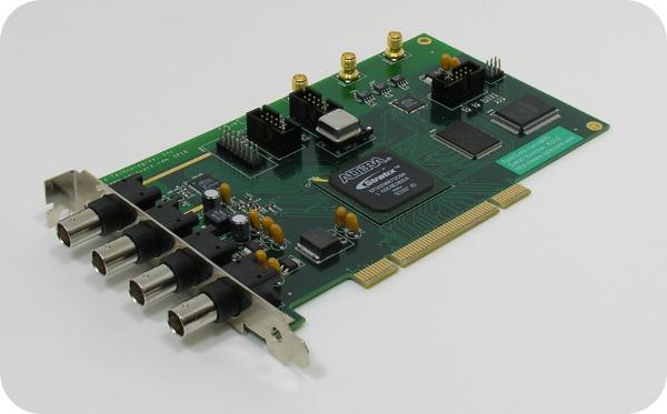
18 V. Connecting to the RadioProcessor-G PCI RadioProcessor-G Board Connector Information There are two main connector types on the RadioProcessor-G board: the BNC connectors and the SMA connectors see Figure 5 below. BNC connectors are mounted on the PCI bracket and are available outside of the computer. The SMA connectors are mounted on-board and are available inside the computer only. Gradient Outputs BNC4 (Analog In) BNC3 (Analog Out) BNC2 (Digital Out) SMA Connectors BNC1 (Digital Out) JP600 JP601 Figure 5: RadioProcessor-G PCI Connector Locations. BNC Connectors The four BNC connectors provide the primary interface with the RadioProcessor-G PCI board. All headers are impedance matched to 50Ω. BNC4 is the Analog Input, used for data acquisition. BNC3 is the Analog Output port. BNC2 and BNC1 are both general purpose digital outputs which can be controlled through the pulse program. The analog output connector (BNC3), is not equipped with an interpolating filter. This allows for maximum flexibility in output frequency, but it means that the output may appear somewhat quantized if no filter is used at the output. To eliminate this behavior and obtain a smooth RF pulse, the user should filter the output with a band-pass or low-pass filter which will cut off the undesired frequency components above the intended RF signal. When using coaxial transmission lines, please terminate the lines with a 50 ohm impedance. See Figures 6 and 7 below. Figure 6: Left: BNC T-Adapter (F M F) and Right: BNC (M) 50 Ohm Impedance

19 Figure 7: BNC T-Adapter on oscilloscope with coaxial transmission line connected on the left and BNC 50 Ohm Impedance connected on the right, to terminate the line. SMA Connectors There are three SMA connectors on the RadioProcessor-G board, all of which are used for gradient voltage outputs. Please note that in the Gradient Echo Experiment, as well as in the MRI SpinAPI, the gradient outputs are labeled as follows: output 3 is the Slice Gradient; output 2 is the Phase Gradient, and output 1 is the Readout Gradient. Hardware Trigger/Reset Header (JP601) The shrouded IDC header JP601 is the Hardware Trigger/Reset connector. This is an input connector, for hardware triggering (HW_Trigger) and resetting (HW_Reset). Please reference Figure 8 and Table 4 below. The recommended mating connector for header JP601 can be obtained through Digi-Key Part Number: ND
20 Figure 8: JP601: Hardware Trigger/Reset Header pin out Table 4: Shrouded IDC Output Header J601 signal list. Pin number Function 1 Reset 2 Ground 3 Trigger 4 Ground 5 LED0 6 Ground 7 LED1 8 Ground 9 LED2 10 Ground HW_Trigger (pin 3) When this input is set to logical 0 (for example by shorting it with pin 4), a hardware trigger is produced. This has the same effects as issuing a trigger through software, although the hardware trigger is more precise, since there are no software latencies involved. HW_Reset (pin 1) When this input is set to logical 0 (for example by shorting it with pin 2), the pulse program is reset
21 Digital Output Header (JP600) The unshrouded male header labeled JP600 contains two digital outputs and eight ground pins. Figure 9 and Table 5 provide visual explanations of the pinout. The recommended mating connector for header JP600 can be obtained on Digi-Key, Part Number: ND. Figure 9: Unshrouded IDC Output Header J600 Table 5: Unshrouded IDC Output Header J600 signal list. Pin number Function 1 Output 3 2 Ground 3 Output 4 4 Ground 5 Not Connected 6 Ground 7 Not Connected 8 Ground 9 Not Connected 10 Ground 11 Not Connected 12 Ground 13 Not Connected 14 Ground 15 Not Connected 16 Ground
22 Related Products and Accessories RadioProcessor-G 1. Consider PBDDS line of products for second channel excitation or decoupling. For more information, please visit our RF and Arbitrary Waveform Generation section on our Products page Consider ispin-nmr for your complete, mobile NMR unit. Please visit our ispin-nmr webpage for more information Consider magnets and probes. For more information, please visit 4. Consider complete MRI system in a small single-bay enclosure. Please inquire with SpinCore Technologies through our contact form, which is available at 5. If you require an Oven Controlled Clock Oscillator (sub-ppm stability) or broadband pre-amplifier, please inquire with SpinCore Technologies through our contact form, which is available at Contact Information SpinCore Technologies, Inc NW 53rd Avenue, SUITE 103 Gainesville, FL USA Telephone (USA): Fax (USA): Website: Web Contact Form: Document Information Revision history is available from SpinCore
RF Power Amplifier PA15W Owner s Manual SpinCore Technologies, Inc.
 RF Power Amplifier PA15W Owner s Manual SpinCore Technologies, Inc. http://www.spincore.com Congratulations and thank you for choosing a design from SpinCore Technologies, Inc. We appreciate your business!
PulseBlasterDDS. Model DDS-II-300 USB Owner s Manual. SpinCore Technologies, Inc.
 PulseBlasterDDS Model DDS-II-300 USB Owner s Manual SpinCore Technologies, Inc. Congratulations and thank you for choosing a design from SpinCore Technologies, Inc. We appreciate your business! At SpinCore
RadioProcessor. Owner s Manual. SpinCore Technologies, Inc.
 Owner s Manual SpinCore Technologies, Inc. http:// Congratulations and thank you for choosing a design from SpinCore Technologies, Inc. We appreciate your business! At SpinCore we try to fully support
ispin-nmr Owner s Manual SpinCore Technologies, Inc.
 Owner s Manual SpinCore Technologies, Inc. http:// Congratulations and thank you for choosing a design from SpinCore Technologies, Inc. We appreciate your business! At SpinCore we try to fully support
SpinCore RadioProcessor LabVIEW Extensions
 NMR Interface User's Manual SpinCore Technologies, Inc. http:// Congratulations and thank you for choosing a design from SpinCore Technologies, Inc. We appreciate your business! At SpinCore we try to fully
ispin-nmr Model GX-35
 ispin-nmr Model GX-35 Part Number: GX-35-mk0 Rev1 Owner s Manual SpinCore Technologies, Inc., Congratulations and thank you for choosing a design from SpinCore Technologies, Inc. We appreciate your business!
ispin-nmr Model GX-5 Part Number: GX-5-mk0 Rev1 Owner s Manual SpinCore Technologies, Inc.
 ispin-nmr Model GX-5 Part Number: GX-5-mk0 Rev1 Owner s Manual SpinCore Technologies, Inc. http:// Congratulations and thank you for choosing a design from SpinCore Technologies, Inc. We appreciate your
ArbStudio Arbitrary Waveform Generators. Powerful, Versatile Waveform Creation
 ArbStudio Arbitrary Waveform Generators Powerful, Versatile Waveform Creation UNMATCHED WAVEFORM UNMATCHED WAVEFORM GENERATION GENERATION Key Features 125 MHz bandwidth 1 GS/s maximum sample rate Long
ArbStudio Arbitrary Waveform Generators
 ArbStudio Arbitrary Waveform Generators Key Features Outstanding performance with 16-bit, 1 GS/s sample rate and 2 Mpts/Ch 2 and 4 channel models Digital pattern generator PWM mode Sweep and burst modes
EVDP610 IXDP610 Digital PWM Controller IC Evaluation Board
 IXDP610 Digital PWM Controller IC Evaluation Board General Description The IXDP610 Digital Pulse Width Modulator (DPWM) is a programmable CMOS LSI device, which accepts digital pulse width data from a
Signal Forge. Signal Forge 1000 TM Synthesized Signal Generator. Digital and RF Tester with 1 GHz Range. Key Features
 Signal Forge TM Signal Forge 1000 TM Synthesized Signal Generator L 8.5 W 5.4 H 1.5 Digital and RF Tester with 1 GHz Range The Signal Forge 1000 combines a 1 GHz frequency range with three dedicated outputs
2015 Spin echoes and projection imaging
 1. Spin Echoes 1.1 Find f0, transmit amplitudes, and shim settings In order to acquire spin echoes, we first need to find the appropriate scanner settings using the FID GUI. This was all done last week,
LC-10 Chipless TagReader v 2.0 August 2006
 LC-10 Chipless TagReader v 2.0 August 2006 The LC-10 is a portable instrument that connects to the USB port of any computer. The LC-10 operates in the frequency range of 1-50 MHz, and is designed to detect
A DSP IMPLEMENTED DIGITAL FM MULTIPLEXING SYSTEM
 A DSP IMPLEMENTED DIGITAL FM MULTIPLEXING SYSTEM Item Type text; Proceedings Authors Rosenthal, Glenn K. Publisher International Foundation for Telemetering Journal International Telemetering Conference
Signal Forge 1800M Frequency Expansion Module. 1.0 GHz to 1.8 GHz. User Manual
 TM TM Signal Forge 1800M Frequency Expansion Module 1.0 GHz to 1.8 GHz User Manual Technical Support Email: Support@signalforge.com Phone: 512.275.3733 x2 Contact Information Web: www.signalforge.com
FlexDDS-NG DUAL. Dual-Channel 400 MHz Agile Waveform Generator
 FlexDDS-NG DUAL Dual-Channel 400 MHz Agile Waveform Generator Excellent signal quality Rapid parameter changes Phase-continuous sweeps High speed analog modulation Wieserlabs UG www.wieserlabs.com FlexDDS-NG
Models FSW-0010 FSW-0020
 MICROWAVE FREQUENCY SYNTHESIZERS Features: 0.1 to 10 GHz and 0.2 to 20 GHz Coverage 0.001 Hz Resolution Power Calibration and Control 100 μs Frequency Switching Instrument-Grade Spectral Purity QuickSyn
DST501-1 High-Speed Modulated Arbitrary Chirping Module
 High-Speed Modulated Arbitrary Chirping Module PRODUCT DESCRIPTION The module generates modulated arbitrary chirping CW with frequency update rates up to 250 updates/microsecond (1/8 of the DDS clock rate).
THE INSTRUMENT. I. Introduction
 THE INSTRUMENT I. Introduction Teach Spin's PS1-A is the first pulsed nuclear magnetic resonance spectrometer signed specifically for teaching. It provides physics, chemistry, biology, geology, and other
Signal Forge. Signal Forge 1000 TM Synthesized Signal Generator. Flexible Design Enables Testing of RF and Clock-driven Systems.
 Signal Forge TM Signal Forge 1000 TM Synthesized Signal Generator L 8.5 W 5.4 H 1.5 Flexible Design Enables Testing of RF and Clock-driven Systems The Signal Forge 1000 combines a 1 GHz frequency range
Model 310H Fast 800V Pulse Generator
 KEY FEATURES Temperature Stability +/-5ppm 100 V to 800 V into 50 Ω
IVI STEP TYPES. Contents
 IVI STEP TYPES Contents This document describes the set of IVI step types that TestStand provides. First, the document discusses how to use the IVI step types and how to edit IVI steps. Next, the document
Signal Forge 2500M Frequency Expansion Module. 1.5 GHz to 2.6 GHz. User Manual
 TM TM Signal Forge 2500M Frequency Expansion Module 1.5 GHz to 2.6 GHz User Manual Technical Support Email: Support@signalforge.com Phone: 512.275.3733 x2 Contact Information Web: www.signalforge.com Sales
WiNRADiO WR-G35DDCi Multichannel Coherent Application Guide
 WiNRADiO WR-G35DDCi Multichannel Coherent Application Guide 1 Table of contents 1 Introduction... 3 2 Parts description of the coherent system... 4 2.1 WR-G35DDCi connectors... 4 2.2 The WiNRADiO Coherence
MRI & NMR spectrometer
 AMOS MRI & NMR spectrometer The AMOS Spectrometer is a highly modular and flexible unit that provides the ability to customize synchronized configurations for preclinical and clinical MR applications.
ArbStudio Training Guide
 ArbStudio Training Guide Summary This guide provides step by step instructions explaining how to create waveforms, use the waveform sequencer, modulate waveforms and generate digital patterns. The exercises
TECHNICAL MANUAL TM0110-2
 TECHNICAL MANUAL TM0110-2 RUBIDIUM FREQUENCY STANDARD MODEL FE-5680A SERIES OPTION 2 OPERATION AND MAINTENANCE INSTRUCTIONS Rubidium Frequency Standard Model FE-5680A with Option 2 Frequency Electronics,
MODELS 5251/ MS/s PXIBus / PCIBus Arbitrary Waveform / Function Generators
 250MS/s PXIBus / PCIBus Arbitrary 5251: Single Channel PXIBus waveform generator 5351: Single Channel PCIBus waveform generator Sine waves to 100MHz and Square to 62.5MHz 16 Bit amplitude resolution 2M
Your first NMR measurement
 Your first NMR measurement Introduction Select 10mM water in D2O as NMR sample. The NMR spectrum of such sample consists of only two signals: the water signal and the peak of the reference (TSP). Follow
10. Phase Cycling and Pulsed Field Gradients Introduction to Phase Cycling - Quadrature images
 10. Phase Cycling and Pulsed Field Gradients 10.1 Introduction to Phase Cycling - Quadrature images The selection of coherence transfer pathways (CTP) by phase cycling or PFGs is the tool that allows the
MODEL AND MODEL PULSE/PATTERN GENERATORS
 AS TEE MODEL 12010 AND MODEL 12020 PULSE/PATTERN GENERATORS Features: 1.6GHz or 800MHz Models Full Pulse and Pattern Generator Capabilities Programmable Patterns o User Defined o 16Mbit per channel o PRBS
Model 845-M Low Noise Synthesizer
 Model 845-M Low Noise Synthesizer Features Low phase noise Fast switching down to 20 µs FM, Chirps, Pulse Internal OCXO, external variable reference Single DC supply Applications ATE LO for frequency converters
Model 305 Synchronous Countdown System
 Model 305 Synchronous Countdown System Introduction: The Model 305 pre-settable countdown electronics is a high-speed synchronous divider that generates an electronic trigger pulse, locked in time with
FREQUENCY SYNTHESIZERS, SIGNAL GENERATORS
 SYNTHESIZED SIGNAL GENERATOR MG3641A/MG3642A 12 khz to 1040/2080 MHz NEW New Anritsu synthesizer technology permits frequency to be set with a resolution of 0.01 Hz across the full frequency range. And
P a g e 1 ST985. TDR Cable Analyzer Instruction Manual. Analog Arts Inc.
 P a g e 1 ST985 TDR Cable Analyzer Instruction Manual Analog Arts Inc. www.analogarts.com P a g e 2 Contents Software Installation... 4 Specifications... 4 Handling Precautions... 4 Operation Instruction...
Contents. ZT530PCI & PXI Specifications. Arbitrary Waveform Generator. 16-bit, 400 MS/s, 2 Ch
 ZT530PCI & PXI Specifications Arbitrary Waveform Generator 16-bit, 400 MS/s, 2 Ch Contents Outputs... 2 Digital-to-Analog Converter (DAC)... 3 Internal DAC Clock... 3 Spectral Purity... 3 External DAC
Synthesized Function Generators DS MHz function and arbitrary waveform generator
 Synthesized Function Generators DS345 30 MHz function and arbitrary waveform generator DS345 Function/Arb Generator 1 µhz to 30.2 MHz frequency range 1 µhz frequency resolution Sine, square, ramp, triangle
DATA SHEET. LitePoint IQflex LitePoint Corporation. All rights reserved.
 DATA SHEET 2011 LitePoint Corporation. All rights reserved. Introduction The IQflex 802.11a/b/g/n WLAN and Bluetooth Test Solution is an all-in-one test instrument developed specifically for RF testing
Model 745 Series. Berkeley Nucleonics Test, Measurement and Nuclear Instrumentation since Model 845-M Specification 1.8 BNC
 Specification 1.8 Model 745 Series 0.01-20.0 GHz Low Phase Noise Synthesizer 250 fs Digital Delay Generator Berkeley Nucleonics Test, Measurement and Nuclear Instrumentation since 1963 Introduction The
ADQ214. Datasheet. Features. Introduction. Applications. Software support. ADQ Development Kit. Ordering information
 ADQ214 is a dual channel high speed digitizer. The ADQ214 has outstanding dynamic performance from a combination of high bandwidth and high dynamic range, which enables demanding measurements such as RF/IF
Model 855 RF / Microwave Signal Generator
 Features Very low phase noise Fast switching Phase coherent switching option 2 to 8 phase coherent outputs USB, LAN, GPIB interfaces Applications Radar simulation Quantum computing High volume automated
AWG-GS bit 2.5GS/s Arbitrary Waveform Generator
 KEY FEATURES 2.5 GS/s Real Time Sample Rate 14-bit resolution 2 Channels Long Memory: 64 MS/Channel Direct DAC Out - DC Coupled: 1.6 Vpp Differential / 0.8 Vpp > 1GHz Bandwidth RF Amp Out AC coupled -10
HS-xx-mux. User s Manual. Multiplexing Headstage that allows recording on 16 to 64 individual electrodes
 HS-xx-mux User s Manual Multiplexing Headstage that allows recording on 16 to 64 individual electrodes 10/24/2017 Neuralynx, Inc. 105 Commercial Drive, Bozeman, MT 59715 Phone 406.585.4542 Fax 866.585.1743
USB Multifunction Arbitrary Waveform Generator AWG2300. User Guide
 USB Multifunction Arbitrary Waveform Generator AWG2300 User Guide Contents Safety information... 3 About this guide... 4 AWG2300 specifications... 5 Chapter 1. Product introduction 1 1. Package contents......
CompuGen PCI Hardware Manual and Driver Installation Guide
 CompuGen PCI Hardware Manual and Driver Installation Guide P/N: 0045511 Reorder #: MKT-HWM-CGPCI02 0512 Copyright Gage Applied Technologies 2005, 2006 Second Edition (March 2006) COMPUSCOPE, COMPUGEN,
SC5307A/SC5308A 100 khz to 6 GHz RF Downconverter. Datasheet SignalCore, Inc.
 SC5307A/SC5308A 100 khz to 6 GHz RF Downconverter Datasheet 2017 SignalCore, Inc. support@signalcore.com P RODUCT S PECIFICATIONS Definition of Terms The following terms are used throughout this datasheet
Agilent N7509A Waveform Generation Toolbox Application Program
 Agilent N7509A Waveform Generation Toolbox Application Program User s Guide Second edition, April 2005 Agilent Technologies Notices Agilent Technologies, Inc. 2005 No part of this manual may be reproduced
MG3740A Analog Signal Generator. 100 khz to 2.7 GHz 100 khz to 4.0 GHz 100 khz to 6.0 GHz
 Data Sheet MG3740A Analog Signal Generator 100 khz to 2.7 GHz 100 khz to 4.0 GHz 100 khz to 6.0 GHz Contents Definitions, Conditions of Specifications... 3 Frequency... 4 Output Level... 5 ATT Hold...
TG1010A AIM & THURLBY THANDAR INSTRUMENTS. 10MHz programmable DDS function generator. Direct Digital Synthesis
 AIM & THURLBY THANDAR INSTRUMENTS TG1010A 10MHz programmable DDS function generator Arbitrary Waveform Capability, Extensive Modulation Modes Direct Digital Synthesis All the versatility of a function
Publication Number ATFxxB Series DDS FUNCTION WAVEFORM GENERATOR. User s Guide
 Publication Number 101201 ATFxxB Series DDS FUNCTION WAVEFORM GENERATOR User s Guide Introduction This user's guide is used for all models of ATFxxB series of DDS function generator. xx in the model number
Lab 8 6.S02 Spring 2013 MRI Projection Imaging
 1. Spin Echos 1.1 Find f0, TX amplitudes, and shim settings In order to acquire spin echos, we first need to find the appropriate scanner settings using the FID GUI. This was all done last week, but these
PROGRAMMABLE INTRACRANIAL SELF- STIMULATION (ICSS) CURRENT STIMULATOR
 CURRENT STIMULATOR") instrumentation and software for research PROGRAMMABLE INTRACRANIAL SELF- STIMULATION (ICSS) CURRENT STIMULATOR PHM-15X USER S MANUAL DOC-012 Rev. 1.8 Copyright 2012 All Rights Reserved Med Associates
instrumentation and software for research PROGRAMMABLE INTRACRANIAL SELF- STIMULATION (ICSS) CURRENT STIMULATOR PHM-15X USER S MANUAL DOC-012 Rev. 1.8 Copyright 2012 All Rights Reserved Med Associates
AWG414 4-GSPS 12-bit Dual-Channel Arbitrary Waveform Generator
 AWG414 4-GSPS 12-bit Dual-Channel Arbitrary Waveform Generator PRODUCT DESCRIPTION The AWG414 modules generate dual channel arbitrary CW waveforms with sampling rates up to 4 GSPS. The on-board SRAMs provide
DAC A (VCO) Buffer (write) DAC B (AGC) Buffer (write) Pulse Code Buffer (write) Parameter Buffer (write) Figure A.1. Receiver Controller Registers
 Buffer (write) DAC B (AGC) Buffer (write) Pulse Code Buffer (write) Parameter Buffer (write) Figure A.1. Receiver Controller Registers") Appendix A. Host Computer Interface The host computer interface is contained on a plug-in module designed for the IBM PC/XT/AT bus. It includes the converters, counters, registers and programmed-logic
Appendix A. Host Computer Interface The host computer interface is contained on a plug-in module designed for the IBM PC/XT/AT bus. It includes the converters, counters, registers and programmed-logic
AD9772A - Functional Block Diagram
 F FEATURES single 3.0 V to 3.6 V supply 14-Bit DAC Resolution 160 MPS Input Data Rate 67.5 MHz Reconstruction Passband @ 160 MPS 74 dbc FDR @ 25 MHz 2 Interpolation Filter with High- or Low-Pass Response
Introduction to Oscilloscopes Instructor s Guide
 Introduction to Oscilloscopes A collection of lab exercises to introduce you to the basic controls of a digital oscilloscope in order to make common electronic measurements. Revision 1.0 Page 1 of 25 Copyright
AWG801 8 GSPS 11-bit Arbitrary Waveform Generator
 AWG801 8 GSPS 11-bit Arbitrary Waveform Generator PRODUCT DESCRIPTION The AWG801 modules generate arbitrary CW waveforms with sampling rates up to 8 GSPS. The on-board SRAMs provide 8M x 11-bit data memory.
DSM303-V4 3.0 GHz Arbitrary Frequency Chirping Module
 DSM303-V4 3.0 GHz Arbitrary Frequency Chirping Module PRODUCT DESCRIPTION The DSM303-V4 module generates arbitrary frequency chirping CW with frequency update rates up to 312.5 updates/microsecond (1/8
HP 33120A Function Generator / Arbitrary Waveform Generator
 Note: Unless otherwise indicated, this manual applies to all Serial Numbers. The HP 33120A is a high-performance 15 MHz synthesized function generator with built-in arbitrary waveform capability. Its combination
SC5407A/SC5408A 100 khz to 6 GHz RF Upconverter. Datasheet. Rev SignalCore, Inc.
 SC5407A/SC5408A 100 khz to 6 GHz RF Upconverter Datasheet Rev 1.2 2017 SignalCore, Inc. support@signalcore.com P R O D U C T S P E C I F I C A T I O N S Definition of Terms The following terms are used
About the DSR Dropout, Surge, Ripple Simulator and AC/DC Voltage Source
 About the DSR 100-15 Dropout, Surge, Ripple Simulator and AC/DC Voltage Source Congratulations on your purchase of a DSR 100-15 AE Techron dropout, surge, ripple simulator and AC/DC voltage source. The
Design Implementation Description for the Digital Frequency Oscillator
 Appendix A Design Implementation Description for the Frequency Oscillator A.1 Input Front End The input data front end accepts either analog single ended or differential inputs (figure A-1). The input
PXIe Contents. Required Software CALIBRATION PROCEDURE
 CALIBRATION PROCEDURE PXIe-5160 This document contains the verification and adjustment procedures for the PXIe-5160. Refer to ni.com/calibration for more information about calibration solutions. Contents
PHY3902 PHY3904. Nuclear magnetic resonance Laboratory Protocol
 PHY3902 PHY3904 Nuclear magnetic resonance Laboratory Protocol PHY3902 PHY3904 Nuclear magnetic resonance Laboratory Protocol GETTING STARTED You might be tempted now to put a sample in the probe and try
Model Number Guide. M= Material. S= Apperture Size. P= Options
 Model Number Guide Brimrose Corporation of America manufactures both standard (from the specification sheet) and custom (to customer specifications) Acousto-Optic Tunable Filters. The following Model Number
Rigol DG1022A Function / Arbitrary Waveform Generator
 Rigol DG1022A Function / Arbitrary Waveform Generator The Rigol DG1000 series Dual-Channel Function/Arbitrary Waveform Generator adopts DDS (Direct Digital Synthesis) technology to provide stable, high-precision,
Stratix Filtering Reference Design
 Stratix Filtering Reference Design December 2004, ver. 3.0 Application Note 245 Introduction The filtering reference designs provided in the DSP Development Kit, Stratix Edition, and in the DSP Development
Model 745 Series. Berkeley Nucleonics Test, Measurement and Nuclear Instrumentation since Model 845-HP Datasheet BNC
 Model 845-HP Datasheet Model 745 Series Portable 20+ GHz Microwave Signal Generator High Power +23dBM Power Output 250 fs Digital Delay Generator BNC Berkeley Nucleonics Test, Measurement and Nuclear Instrumentation
GPS Time and Frequency Reference Receiver
 $ GPS Time and Frequency Reference Receiver Symmetricom s 58540A GPS time and frequency reference receiver features: Eight-channel, parallel tracking GPS engine C/A Code, L1 Carrier GPS T-RAIM satellite
High-speed programmable attenuator MAT800
 High-speed programmable attenuator MAT800 Windows98/Me/2000/XP/Vista/7(32bit) correspondence GP-IB, RS-232C and software for making attenuation program are standard accessories. Optimum for evaluation
SIGNAL GENERATORS. MG3633A 10 khz to 2700 MHz SYNTHESIZED SIGNAL GENERATOR GPIB
 SYNTHESIZED SIGNAL GENERATOR MG3633A GPIB For Evaluating of Quasi-Microwaves and Measuring High-Performance Receivers The MG3633A has excellent resolution, switching speed, signal purity, and a high output
PN9000 PULSED CARRIER MEASUREMENTS
 The specialist of Phase noise Measurements PN9000 PULSED CARRIER MEASUREMENTS Carrier frequency: 2.7 GHz - PRF: 5 khz Duty cycle: 1% Page 1 / 12 Introduction When measuring a pulse modulated signal the
USB-TEMP and TC Series USB-Based Temperature Measurement Devices
 USB-Based Temperature Measurement Devices Features Temperature and voltage measurement USB devices Thermocouple, RTD, thermistor, or semiconductor sensor measurements Eight analog inputs Up to ±10 V inputs*
Combinational logic: Breadboard adders
 ! ENEE 245: Digital Circuits & Systems Lab Lab 1 Combinational logic: Breadboard adders ENEE 245: Digital Circuits and Systems Laboratory Lab 1 Objectives The objectives of this laboratory are the following:
MULT SWP X1K K VERN START FREQ DURATION AMPLITUDE 0 TTL OUT RAMP
 Signal Generators This document is a quick reference guide to the operation of the signal generators available in the laboratories. Major functions will be covered, but some features such as their sweep
QuickSyn Frequency Synthesizers
 QuickSyn Frequency Synthesizers The QuickSyn Advantage Our popular line of QuickSyn frequency synthesizers delivers instrumentgrade performance up to 82 GHz, increased functionality, and efficient power
3010 Programmable Frequency Divider
 31 Programmable Frequency Divider 5 to 2GHz input Rugged milled aluminum housing RFI shielded construction EMI/EMC enhanced circuitry ESD protected Accepts input signal
ESE 350 Microcontroller Laboratory Lab 5: Sensor-Actuator Lab
 ESE 350 Microcontroller Laboratory Lab 5: Sensor-Actuator Lab The purpose of this lab is to learn about sensors and use the ADC module to digitize the sensor signals. You will use the digitized signals
SonoLab Echo-I User Manual
 SonoLab Echo-I User Manual Overview: SonoLab Echo-I is a single board digital ultrasound pulse-echo solution. The system has a built in 50 volt high voltage generation circuit, a bipolar pulser, a transmit/receive
WaveStation Function/Arbitrary Waveform Generators
 WaveStation Function/Arbitrary Waveform Generators Key Features High performance with 14-bit, 125 MS/s and 16 kpts 2 channels on all models Large 3.5 color display for easy waveform preview Over 40 built-in
Faculty of Information Engineering & Technology. The Communications Department. Course: Advanced Communication Lab [COMM 1005] Lab 6.
![Faculty of Information Engineering & Technology. The Communications Department. Course: Advanced Communication Lab [COMM 1005] Lab 6.](/thumbs/90/102233011.jpg "Faculty of Information Engineering & Technology. The Communications Department. Course: Advanced Communication Lab [COMM 1005] Lab 6.") Faculty of Information Engineering & Technology The Communications Department Course: Advanced Communication Lab [COMM 1005] Lab 6.0 NI USRP 1 TABLE OF CONTENTS 2 Summary... 2 3 Background:... 3 Software
Faculty of Information Engineering & Technology The Communications Department Course: Advanced Communication Lab [COMM 1005] Lab 6.0 NI USRP 1 TABLE OF CONTENTS 2 Summary... 2 3 Background:... 3 Software
Agilent 8360B Series Synthesized Swept Signal Generators 8360L Series Synthesized Swept CW Generators Data Sheet
 Agilent 8360B Series Synthesized Swept Signal Generators 8360L Series Synthesized Swept CW Generators Data Sheet 10 MHz to 110 GHz Specifications apply after full user calibration, and in coupled attenuator
NI 6013/6014 Family Specifications
 NI 6013/6014 Family Specifications This document lists the I/O terminal summary and specifications for the NI 6013/6014 family of devices. This family includes the following devices: NI PCI-6013 NI PCI-6014
SDI SPECTRADYNAMICS, INC GHZ RUBIDIUM FREQUENCY SYNTHESIZER OPERATING MANUAL
 SPECTRADYNAMICS, INC. 6.834 GHZ RUBIDIUM FREQUENCY SYNTHESIZER RB-1 OPERATING MANUAL SPECTRADYNAMICS, INC 1849 Cherry St. Unit 2 Louisville, CO 80027 Phone: (303) 665-1852 Fax: (303) 604-6088 www.spectradynamics.com
Ultrasonic Multiplexer OPMUX v12.0
 Przedsiębiorstwo Badawczo-Produkcyjne OPTEL Sp. z o.o. ul. Morelowskiego 30 PL-52-429 Wrocław tel.: +48 (071) 329 68 54 fax.: +48 (071) 329 68 52 e-mail: optel@optel.pl www.optel.eu Ultrasonic Multiplexer
10 MHz Function Generator Module
 User's Manual 10 MHz Function Generator Module 3rd Edition 3rd Edition Thank you for purchasing the 10 MHz Function Generator Module WE7121 for the PCbased measurement instruments, WE7000. This User s
Gentec-EO USA. T-RAD-USB Users Manual. T-Rad-USB Operating Instructions /15/2010 Page 1 of 24
 Gentec-EO USA T-RAD-USB Users Manual Gentec-EO USA 5825 Jean Road Center Lake Oswego, Oregon, 97035 503-697-1870 voice 503-697-0633 fax 121-201795 11/15/2010 Page 1 of 24 System Overview Welcome to the
Getting Started. MSO/DPO Series Oscilloscopes. Basic Concepts
 Getting Started MSO/DPO Series Oscilloscopes Basic Concepts 001-1523-00 Getting Started 1.1 Getting Started What is an oscilloscope? An oscilloscope is a device that draws a graph of an electrical signal.
PXIe Contents. Required Software CALIBRATION PROCEDURE
 CALIBRATION PROCEDURE PXIe-5113 This document contains the verification and adjustment procedures for the PXIe-5113. Refer to ni.com/calibration for more information about calibration solutions. Contents
Appendix C. LW400-09A Digital Output Option
 LW400-09A Digital Output Option Introduction The LW400-09A Digital Output option provides 8-bit TTL and ECL, digital outputs corresponding to the current value of the channel 1 analog output. The latched
MODEL 625A SMARTARB BNC A BEST BUY. Eliminates Phase Jitter
 A BEST BUY The Model 625A SMARTARB was designed to provide more operating modes, more functions and more measurement modes than any other unit in its price class. Further upgrading and additions of these
SIGNAL RECOVERY. Model 7265 DSP Lock-in Amplifier
 Model 7265 DSP Lock-in Amplifier FEATURES 0.001 Hz to 250 khz operation Voltage and current mode inputs Direct digital demodulation without down-conversion 10 µs to 100 ks output time constants Quartz
Arbitrary/Function Waveform Generators 4075B Series
 Data Sheet Arbitrary/Function Waveform Generators Point-by-Point Signal Integrity The Arbitrary/Function Waveform Generators are versatile high-performance single- and dual-channel arbitrary waveform generators
Agilent 33522A Function Arbitrary Waveform Generator. Tektronix TDS 3012B Oscilloscope
 Agilent 33522A Function/Arbitrary Waveform Generator and Tektronix TDS 3012B Oscilloscope Agilent 33522A Function Arbitrary Waveform Generator The signal source for this lab is the Agilent 33522A Function
Model 865-M Wideband Synthesizer
 Model 865-M Wideband Synthesizer Features Wideband Low phase noise Fast switching down to 20 µs FM, Chirps, Pulse Internal OCXO, external variable reference Single DC supply Applications ATE LO for frequency
ISMRM weekend educational course, MR Systems Engineering, Console Electronics
 ISMRM weekend educational course, MR Systems Engineering, Console Electronics. 2013-4-20 Declaration of Relevant Financial Interests or Relationships Speaker Name: Katsumi Kose, Ph.D. I have the following
Stratix II Filtering Lab
 October 2004, ver. 1.0 Application Note 362 Introduction The filtering reference design provided in the DSP Development Kit, Stratix II Edition, shows you how to use the Altera DSP Builder for system design,
5008 Dual Synthesizer Configuration Manager User s Guide (admin Version) Version valontechnology.com
 Version valontechnology.com") 5008 Dual Synthesizer Configuration Manager User s Guide (admin Version) Version 1.6.1 valontechnology.com 5008 Dual Synthesizer Module Configuration Manager Program Version 1.6.1 Page 2 Table of Contents
5008 Dual Synthesizer Configuration Manager User s Guide (admin Version) Version 1.6.1 valontechnology.com 5008 Dual Synthesizer Module Configuration Manager Program Version 1.6.1 Page 2 Table of Contents
NI PXI/PCI-5411/5431 Specifications
 NI PXI/PCI-5411/5431 Specifications NI PXI/PCI-5411 High-Speed Arbitrary Waveform Generator NI PXI/PCI-5431 Video Waveform Generator Analog Output This document lists the specifications for the NI PXI/PCI-5411
Multiple Instrument Station Module
 Multiple Instrument Station Module Digital Storage Oscilloscope Vertical Channels Sampling rate Bandwidth Coupling Input impedance Vertical sensitivity Vertical resolution Max. input voltage Horizontal