ispin-nmr Owner s Manual SpinCore Technologies, Inc.
|
|
|
- Scott Carpenter
- 6 years ago
- Views:
Transcription

1 Owner s Manual SpinCore Technologies, Inc.
2 Congratulations and thank you for choosing a design from SpinCore Technologies, Inc. We appreciate your business! At SpinCore we try to fully support the needs of our customers. If you are in need of assistance, please contact us and we will strive to provide the necessary support SpinCore Technologies, Inc. All rights reserved. SpinCore Technologies, Inc. reserves the right to make changes to the product(s) or information herein without notice. RadioProcessor,, PulseBlaster, SpinCore, and the SpinCore Technologies, Inc. logos are trademarks of SpinCore Technologies, Inc. All other trademarks are the property of their respective owners. SpinCore Technologies, Inc. makes every effort to verify the correct operation of the equipment. This equipment version is not intended for use in a system in which the failure of a SpinCore device will threaten the safety of equipment or person(s). 2
3 Table of Contents I. Introduction... 5 II. Product Overview... 6 III. Typical Application... 7 IV. General Operation Description... 8 V. Inside the... 9 VI. Connector Information (Single-Bay) RF Connectors Digital (TTL) Connector USB Connector Hardware Reset/Trigger Connectors VII. Using the System Testing : Step-by-step Instructions Conducting an NMR Experiment with the : Step-by-step Instructions...19 VIII. MATLAB GUI Interface Overview of SpinCore MATLAB GUI Interface General Features: Sample Screenshots IX. LabVIEW NMR Interface Overview of SpinCore LabVIEW GUI Interface X. Pre-amplifier Filter Selection Considerations...27 XI. Power Amplifier Precautions Connecting & Disconnecting Power Amplifiers Power Considerations XII. Related Products and Accessories XIII. Contact Information
4 XIV. Document Information
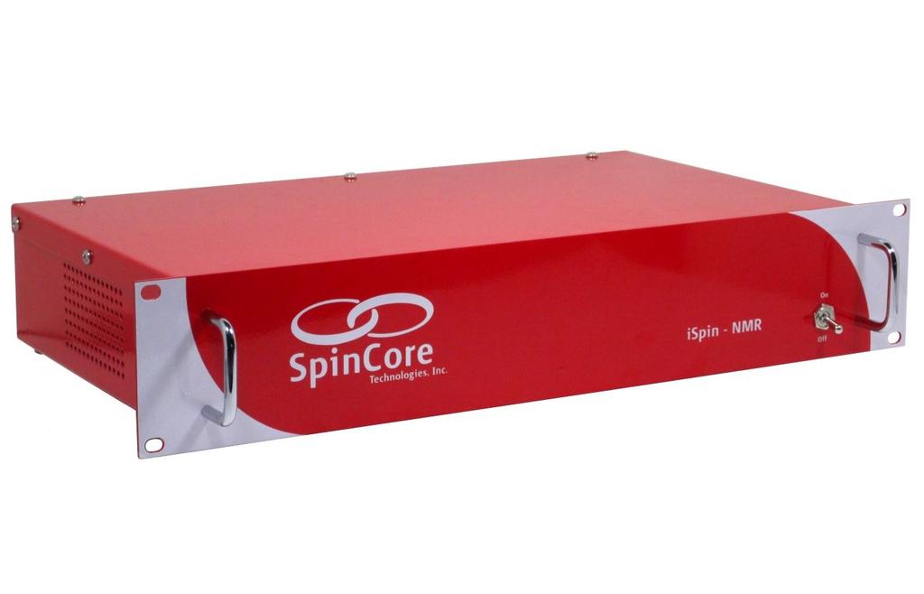
5 I. Introduction The TM is SpinCore's Portable Broadband NMR system. Built around the RadioProcessor board and SpinCore's NMR software, once connected to a probe the is instantly ready to perform NMR experiments from 0 to 100 MHz and beyond! * This manual provides all the information you need to get started with your system, and includes sections on typical applications with connection diagrams, detailed descriptions of the 's internal components, connector information, testing and experiment procedures and more. For more details about technical information pertaining to SpinCore's RadioProcessor board the primary component of the system, responsible for all digital control and signal processing or information about writing your own pulse programs and experiments, the user is encouraged to also read the SpinCore RadioProcessor user manual which can be found at the following location: Should you have any questions that are not answered in either manual, please contact SpinCore Technologies, Inc. using the contact information section at the end of this document. Thank you for choosing SpinCore Technologies, Inc. for your mobile NMR needs, and be sure to visit for the latest information about SpinCore's products! * Certain limitations apply, vide infra. 5
, broadband power amplification unit (Item #2), and broadband pre-amplification unit (Item #3).")
6 II. Product Overview The block diagram of the system is presented in Figure 1. The system console contains SpinCore's USB RadioProcessor board (Item #1), broadband power amplification unit (Item #2), and broadband pre-amplification unit (Item #3). The generates a NMR excitation pulse, amplifies that pulse, and then acquires data from a probe, performing digital detection, filtering and signal averaging autonomously. It connects to any PC or laptop via USB 2.0. Figure 1: system block diagram. The system console is equipped with a universal AC input power supply (90 to 240 VAC) and consumes no more than 80 Watts. The power supply inside the console complies with CE, UL, CSA, and TUV. The metal enclosure meets FCC/FTZ regulations. The system console is RoHS compliant and is intended for operation at room temperature, typically in the range of temperatures from 15 C to 28 C, with a relative humidity limit of 35%70% (non-condensing), no visible moisture, and at altitudes not exceeding 5 km. 6
7 III. Typical Application The is typically used for Nuclear Magnetic Resonance (NMR), Nuclear Quadrupole Resonance (NQR) and Magnetic Resonance Imaging (MRI) applications. The typical connection diagram for those applications is depicted below in Figure 2 Figure 2: Connection Diagram for typical applications. On some systems, the Duplexer, or some of its parts, may be installed inside the system. The sample being studied is placed in the RF coil (antenna) of the probe. The probe is connected to the system via the fast Transmit/Receive switch, comprised of appropriate RF coaxial cables and fast switching diodes. The diodes and the λ/4 cable protect the receiver of the system when excitation pulses are applied, while facilitating the isolation of the transmitter's circuitry from the receiver when acquiring the small-signal response from the sample. NOTE: The system is available in an alternative output configuration. This alternative output configuration has the switching diodes embedded within the enclosure, thus eliminating the need for a Tx cable. 7
8 IV. General Operation Description The is designed to be simple, intuitive and effective. The following is an outline of how the operates for typical NMR/NQR experiments. 1. The user inputs the necessary parameters into SpinCore's NMR GUI or alternative software program. 2. When the user begins the scan, the generates the NMR excitation pulses depending on the input parameters. 3. During specific intervals in the pulse sequence (typically after the excitation pulse in a single-pulse NMR experiment), the system will acquire the data returned from the sample in the sample probe. The system digitizes the signal and performs digital detection, filtering, and autonomous signal averaging. The processed digital values are stored on the console and are available for download to the host computer at the user's convenience. 4. Transmit/Receive Circuitry (sold as a separate component) will automatically switch between the excitation pulses and the signal input from the probe. The input signal from the sample probe is passed through a lambda-quarter cable (part of the Transmit/Receive switching circuit), fed into a pre-amplifier inside the system, and then follows to the digital receiver on the RadioProcessor board inside the system for digitization and digital signal processing. 5. The system continues to scan the specified number of times, automatically averaging the values stored on chip for each scan. Data may be downloaded to the host computer at any time for inspection, visualization, and processing, without interfering with the ongoing data acquisition. The user can download the data received from the RadioProcessor using SpinCore's NMR GUI, SpinCore's non-gui C/C++ program, or alternative software tools. 6. NMR/NQR data are saved on the host computer in three different formats, including ASCII (plain text file) and JCAMP-DX, for post-acquisition processing, visualization, and analysis. For a more detailed description of operation, please consult section VII, Using the System, in this manual. 8

9 V. Inside the A photograph of the internal components of the older single-bay system is shown below in Figure 3. For descriptions of each component see the following page. Figure 3: Inside the system. 9
10 1. USB RadioProcessor Board: The heart of the system. The RadioProcessor board generates the completely formed excitation signals and then captures and digitally processes the NMR signals. Digital detection, filtering, and autonomous signal averaging are standard features, as well as shaped excitation pulses. For more information on RadioProcessor, including performance characteristics from 0 to 100 MHz, please visit the URL The RF output of the RadioProcessor is connected to the Power Amplifier module, and the RF input is connected directly to the output of the small-signal preamplifier and filter. 2. Power Amplifier: Used to amplify the NMR excitation pulses. The supplied Power Amplifier is broadband, and is able to supply continuous power at the desired frequency of operation. The standard power amplifer used in the system is the PA10W, capable of supplying 20 Watts Peak Envelope Power. There are several others available: the PA15W, capable of supplying 30 Watts Peak Envelope Power, and the PA75W, capable of supplying 150 Watts Peak Envelope Power. For more information, please visit If higher power is needed, a final Power Amplifier stage can be provided with output power ranging from 100 to 1000 Watts. Please contact SpinCore for more details. 3. Preamplifiers and filters: The supplied preamplifiers are broadband, MHz, and provide ~60 db gain.. The preamplifiers are supplemented with band-pass (or low-pass) filters. When ordering, please specify your frequency of interest for the selection of appropriate filters. 4. Input and output RF connectors: BNC Connectors are used for RF signals, connecting with the Transmit/Receive Circuitry. NOTE: Systems that have internal switching diodes will have three SMA connectors instead of two BNC connectors. More information about these connectors can be found in the RF Connectors section on the following page. An additional DB-9 type connector is used to output TTL signals for multi-system synchronization or control of any required peripheral devices. 5. Universal AC Power Supply: Accepts V AC power, Hz. A standard PC power cable can be used. No warm-up time needed/present, a sub-second power-on, no user-serviceable fuse, internally protected, will shut-off when overloaded. Note: The system contains a mechanical Power On switch that can be in two positions: On or Off. If the unit is presently powered with the switch in the On 10
11 position, then it will power on again without manual intervention when the AC power mains is cycled off then on. 6. USB 2.0 Interface: Contains the USB 2.0 interface hardware and software. 7. Large-diameter fan: Included for efficient heat dissipation and quiet operation. 8. Ample space inside: There is plenty of room inside the console for an embedded computer, small permanent magnet, or touch screen, if desired. 11
12 VI. Connector Information (Single-Bay) This section provides information on the single-bay form factor, which is not currently offered. For these older models, it provides descriptions of the external connectors of the ispinnmr. Figure 4, below, shows a sketch of the front and back panels of the system. Figure 4: Front (left) and back (right) sides of the (dimensions are in mm). The size of the enclosure is 180mm x 165mm x 340 mm. The large circles on the back panel represent the fan's exhaust. This exhaust port should not be blocked or covered. 12
13 RF Connectors The standard system has two standard BNC jack (female) connectors that allow for the system to be easily connected to via standard BNC cables. These two RF BNC connectors are labeled RF Power Out and NMR Signal In. NOTE: For systems shipped with the internal switching diodes there are three SMA jack (female) connectors. These three SMA connectors can be easily connected to via standard SMA cables. Two of the SMA connectors are labeled λ/4 Cable and the third connector is labeled To Probe. The left λ/4 connector corresponds to the NMR Signal In and the To Probe corresponds to the RF Power Out. Please see the below figure for an example of the connector layout. Figure 5: Connector layout for an ispin with internal diodes. The circles in this figure represent SMA connectors. CAUTION: Output voltages can reach values greater than 200 V peak-to-peak and can be fatal. CAUTION:A 50 Ω load needs to be present at the RF Power Out or To Probe connector at all times. Digital (TTL) Connector The digital, TTL-compatible, outputs of the are present on the bracket-mounted DB-9 (female) connector marked TTL. The pinout of this connector and the corresponding signal names are shown below in Figure 6. The maximum drive capability in the logical 1 is 15 ma. The maximum sinking current for a logical 0 is 15 ma. NOTE: TTL signal Bit 2 is often connected internally with the input pin of the power amplifier unit. Figure 6: TTL Output Connector (DB9-female) and signal list. 13
14 USB Connector The USB connector is a USB Type-B connector, and can easily be connected to a computer via a standard USB 2.0 cable. Hardware Reset/Trigger Connectors Access to the hardware reset and hardware trigger lines of the RadioProcessor USB is provided via RCA jacks labeled Reset and Trigger. For more information about the function of these pins, please see the SpinCore RadioProcessor manual. 14
15 VII. Using the System Testing : Step-by-step Instructions The is tested extensively before shipment and is ready to use for acquisition of NMR (or NQR) signals out-of-the-box, however, it is suggested that the user tests the upon delivery to make sure there were no damages during shipment and to become more familiar with the operation and performance of individual components. The testing procedure for the system is described below: 1. Download and install the latest SpinAPI package available at: Additionally, very detailed information on each programming function can be found on our SpinAPI References page that is linked from our main SpinAPI page the direct link to that page is On the above page, please select spinapi.h for detailed descriptions of each and every SpinAPI function. Download and install the latest SpinAPI RadioProcessor Examples. The Examples are available at: 2. Connect your system as shown in Figure 7. For ispin's with SMA connectors that match Figure 5, the 'To Probe' connector is the 'RF Power Out' connector and the left 'λ/4' connector is the 'NMR Signal In' connector. Note that pin-4 on the TTL output DB-9 connector is the blanking signal and can be used to trigger the oscilloscope. Turn on your system only after making all connections. 15
16 Figure 7: test setup. The receiver is very sensitive and can detect signals less than 1 μv peak-topeak. The maximum input that can be received without distortion is approximately 2.5 mv peak-to-peak. Be sure to attenuate the signal going into the so it falls in this range. The RF output of the can be as high as 75 W, or 200 V peak-topeak. This voltage is typically too large for an oscilloscope, so be sure to attenuate the output properly. 3. Create your own new working directory somewhere outside of the SpinCore directory and copy the contents of the SpinAPI RadioProcessor Examples to your new working directory. The SpinCore RadioProcessor directory can be found in the location you downloaded the SpinAPI Examples. 4. To test the Transmitter, edit the following parameters in the singlepulse_nmr_example.bat. This file can be edited by right-clicking and selecting edit. REPETITION_DELAY = 0.5 NUMBER_OF_SCANS = 100 SPECTROMETER_FREQUENCY = PULSE_TIME = 10.0 FNAME = tx_test BLANKING_EN = 1 BLANKING_BIT = 2 BLANKING_DELAY = 3.0 AMPLITUDE = 0.1 (seconds) (MHz) (μs) (the output files can be ignored when only testing the transmitter) (ms) All other values can be left as default. 5. After entering the parameters, save the singlepulse_nmr_example.bat file, then run it by double-clicking the file. On the oscilloscope you should see a MHz sine wave 16
17 that is on for 10.0 μs. The amplitude of the sinusoid depends on the attenuation of the RF output signal. This will repeat 100 times every 0.5 seconds and then stop. The diagram in Figure 8, on the following page, shows what a typical oscilloscope output will look like for this test. De-blanking Delay Pulse Time Deblanking Signal RF Output Figure 8: Representation of the oscilloscope output for the transmitter test. The 's internal RF power amplifiers requires a specific de-blanking time, for each model, prior to the RF pulse for full output power. The de-blanking time for each power amplifier can be found in the RF power amplifier manuals, which can be downloaded at 6. Repeat this test a few times, increasing the amplitude setting until you reach your desired output power (up to a maximum of 1.0). The output power should not exceed 10W RMS for a PA10W, 15W RMS for a PA15W, etc. 7. To test the Receiver, edit the following parameters in the singlepulse_nmr_example.bat file: NUMBER_OF_SCANS = 1 NUMBER_POINTS = SPECTROMETER_FREQUENCY = SPECTRAL_WIDTH = 50 BYPASS_FIR = 1 FNAME = rx_test (MHz) (khz) Use the amplitude you determined in step 5 above. 8. After entering the parameters, save the singlepulse_nmr_example.bat file. 17
18 9. Set your frequency source MHz. Notice that this value is 1.0 khz offset from the spectrometer frequency entered in step Run the singlepulse_nmr_example.bat by double-clicking the file. After the scan has completed, the program will generate three output files (rx_test.fid, rx_test.jdx, and rx_test.txt). 11. Open the rx_test.fid file using Felix NMR software (available for 32-bit Windows systems, available for download at: and verify the 1 khz signal. After doing the FFT, you should see a strong signal at 1 khz. Figure 9 shows data captured by the system with a signal attenuated by over 100 db. The time domain signal is on top (expanded) and the FFT is shown on the bottom. Figure 9: Data received by an system performing the Rx test. The input signal is attenuated by over 100 db and is less than 18 μv peak-to-peak. 18
19 Conducting an NMR Experiment with the : Step-bystep Instructions 1. Download and install the latest SpinAPI package available at: Download and install the latest SpinAPI RadioProcessor Examples. The Examples are available at: 2. Connect your system as shown in Figure 2 (page 7). 3. Check all connections and then power on your system. WARNING: A 50 Ohm load MUST be presented to the RF Power Out connector of the system. If no load/probe is connected, or if probe is not properly matched/tuned, you may damage the system. For ispin devices with SMA connectors that match Figure 5, the To Probe connector corresponds to the RF Power Out. If you have any questions, PLEASE contact us. 4. Create your own new working directory somewhere outside of the SpinCore directory and copy the contents of the SpinAPI RadioProcessor Examples to your new working directory. The SpinCore RadioProcessor directory can be found in the location you downloaded the SpinAPI Examples. 5. Edit the singlepulse_nmr_example.bat batch file by right-clicking and selecting edit and save the batch file when finished. The timing values in the batch file correspond to those in Figure 10, on the following page. 6. Run the singlepulse_nmr_example.bat file by double-clicking. Once the singlepulse_nmr.bat file has completed, three new files (*.fid, *.jdx, *.txt) will be created in the directory from which the batch file was executed. 19
20 DeBlanking Signal RF Output NMR Signal De-blanking Delay Pulse Time Transient Time Acquisition Time Repetition Delay Figure 10: Timing diagram for one single pulse NMR scan (not drawn to scale). 7. Load the Felix file (.fid) in Felix for Windows, or load the.jdx file in any program that supports JCAMP-DX. An easily parsed text file containing the NMR data will also be generated. For information on installing and using Felix to view your.fid files, go to The NMR data received should look something like that of the screenshots shown in sections VIII and IX. For information about about specific control signals for NMR tests which would allow for custom NMR experiments, see the SpinCore RadioProcessor manual at 20
21 VIII. MATLAB GUI Interface Overview of SpinCore MATLAB GUI Interface The SpinCore MATLAB GUI Interface is a series of programs created for the MATLAB environment that allows quick and easy interaction with the system. Specifically, this interface is designed to allow users to perform a variety of useful experiments with their system. Complete documentation for the SpinCore MATLAB GUI can be found here: General Features: Run NMR experiments with ease, including Single Pulse, CPMG, and 90 Degree PulseWidth Determination Change experiment parameters quickly and easily Preview data in MATLAB immediately after the scan Combine the versatility of the RadioProcessor with the power of the MATLAB environment Quickly find resonant spectrometer frequency through automatic detection 90 Degree Pulse-Width Finder allows quick and simple detection of important pulse width parameters CPMG NMR now includes a feature to calculate T2 relaxation times for samples with a single exponential Continuous Scan setting for Single Pulse NMR Load and review data from previous Single Pulse NMR experiments within the interface. Note: Versions prior to R5 do not have support for systems. Versions after R8g have full functionality for the for every function. 21


22 Sample Screenshots Figure 11: Sample output after running Single Pulse NMR experiment on household cooking oil. Figure 12: Output as above, displaying Magnitude plot and Semi-log FFT. 22


23 Figure 13: Sample output after running CPMG NMR experiment on household cooking oil. Figure 14: Sample T2 calculation and curve fitting. 23

24 Figure 15: Automatic 90 Degree Pulse Width Determination. 24

25 IX. LabVIEW NMR Interface Overview of SpinCore LabVIEW GUI Interface SpinCore has developed an easy-to-use LabVIEW Graphical User Interface (GUI) that combines the Single Pulse NMR, T1 Inversion Recovery, and CPMG interfaces into one interface. It allows the user to run basic NMR experiments by simply setting the experiment parameters as described elsewhere in this manual. Extra features in LabVIEW GUI include lightning fast resonance finder, built-in FFT and phasing, CYCLOPS phase cycling experiments, 90 degree pulse width finder, and continuous scan mode. The following two figures are screenchots of the LabVIEW NMR Inferface. For more information see the LabVIEW manual at: NOTE: A National Instruments license is not required to run the LabVIEW interface. Figure 16: Example of RadioProcessor LabVIEW Extensions User Interface. 25

26 Figure 17: Example of Pulse Width Finder for LabVIEW NMR Interface. 26
27 X. Pre-amplifier Filter Selection Considerations The receiver is very sensitive to small signals and has a broad input frequency range for maximum versatility. While this feature can be very useful, the broadband receiver may capture unwanted noise if not used correctly. At SpinCore we customize your system to your specific operating frequency and can provide custom band-pass filters at those specific frequencies. Contact SpinCore Technologies for more information. Figure 18, on the following page, shows the receiver sensitivity when connected to a 72 MHz RF signal that is attenuated by 120 db down to less than 1.8 μv peak-to-peak. The left side shows received data using a 98 MHz low-pass filter, and the right side shows received data when using a 72 MHz band-pass filter. The performance benefits of the band-pass filter are clear. Figure 18: Receiver performance using low-pass filters (left) and band-pass filters (right). 27
28 XI. Power Amplifier Precautions Working with RF power amplifiers can be dangerous and even fatal if not handled properly. All precautions should be taken while operating the as an RF power amplifier is used in its operation. Output voltages can reach values greater than 100 V peak-to-peak and can be fatal. Follow these steps to avoid damaging the amplifier or inflicting serious injuries. Connecting & Disconnecting Power Amplifiers When connecting the power amplifier, follow these steps to avoid damaging the amplifier or inflicting serious injuries. 1) Apply the load to the amplifier (make sure a load is ALWAYS present when working with power amplifiers). 2) Apply the DC power to the amplifier. 3) Apply the RF input to the amplifier. Repeat the steps in reverse order when disconnecting the amplifier. Power Considerations Make sure the following considerations have been made before applying power to the amplifier. 1) Be sure your load can appropriately dissipate the maximum power being applied by the amplifier. 2) When applying an RF signal, work with low duty cycles to limit the power being dissipated. The duty cycle ratio should be below 1% for safe operation. 28

29 XII. Related Products and Accessories 1. RadioProcessor: Complete RF Acquisition and Excitation System with Digital Detection, Real-Time Signal Processing and Signal Averaging. For more information, please visit 2. RF Power Amplifiers PA10W, PA15W, PA75W and PA100W. For more information, please visit 3. PulseBlaster: Programmable TTL Pulse Generator / Digital Word Generator and Timing Engine. For more information, please visit 4. SpinCore also offers the following to supplement the system. NMR Magnets Probes Duplexer (Transmit/Receive) Circuitry. Custom RF Filters and Cables. Oven controlled oscillators with sub-ppm stability. 5. All components of the system may be ordered separately. For custom designs, modifications or software development, please inquire with SpinCore Technologies through our contact form, which is available at 6. Optionally, the system is available in a dual bay enclosure (see photo below). The size of this enclosure is mm x 311 mm x mm (Width x Depth x Height). 29
30 XIII. Contact Information SpinCore Technologies, Inc NW 53rd Avenue, SUITE 103 Gainesville, FL USA Telephone (USA): Fax (USA): Website: Web Contact Form: XIV. Document Information Revision History available at SpinCore. 30
ispin-nmr Model GX-35
 ispin-nmr Model GX-35 Part Number: GX-35-mk0 Rev1 Owner s Manual SpinCore Technologies, Inc., Congratulations and thank you for choosing a design from SpinCore Technologies, Inc. We appreciate your business!
ispin-nmr Model GX-5 Part Number: GX-5-mk0 Rev1 Owner s Manual SpinCore Technologies, Inc.
 ispin-nmr Model GX-5 Part Number: GX-5-mk0 Rev1 Owner s Manual SpinCore Technologies, Inc. http:// Congratulations and thank you for choosing a design from SpinCore Technologies, Inc. We appreciate your
RF Power Amplifier PA15W Owner s Manual SpinCore Technologies, Inc.
 RF Power Amplifier PA15W Owner s Manual SpinCore Technologies, Inc. http://www.spincore.com Congratulations and thank you for choosing a design from SpinCore Technologies, Inc. We appreciate your business!
SpinCore RadioProcessor LabVIEW Extensions
 NMR Interface User's Manual SpinCore Technologies, Inc. http:// Congratulations and thank you for choosing a design from SpinCore Technologies, Inc. We appreciate your business! At SpinCore we try to fully
RadioProcessor-G. Owner s Manual. SpinCore Technologies, Inc.
 Owner s Manual SpinCore Technologies, Inc. http:// Congratulations and thank you for choosing a design from SpinCore Technologies, Inc. We appreciate your business! At SpinCore we try to fully support
RadioProcessor. Owner s Manual. SpinCore Technologies, Inc.
 Owner s Manual SpinCore Technologies, Inc. http:// Congratulations and thank you for choosing a design from SpinCore Technologies, Inc. We appreciate your business! At SpinCore we try to fully support
PulseBlasterDDS. Model DDS-II-300 USB Owner s Manual. SpinCore Technologies, Inc.
 PulseBlasterDDS Model DDS-II-300 USB Owner s Manual SpinCore Technologies, Inc. Congratulations and thank you for choosing a design from SpinCore Technologies, Inc. We appreciate your business! At SpinCore
DSA700 Series Spectrum Analyzer
 DSA700 Series Spectrum Analyzer Product Features: All-Digital IF Technology Frequency Range from 100 khz up to 1 GHz Min. -155 dbm Displayed Average Noise Level (Typ.) Min.
WaveStation Function/Arbitrary Waveform Generators
 WaveStation Function/Arbitrary Waveform Generators Key Features High performance with 14-bit, 125 MS/s and 16 kpts 2 channels on all models Large 3.5 color display for easy waveform preview Over 40 built-in
WaveStation Function/Arbitrary Waveform Generators
 WaveStation Function/Arbitrary Waveform Generators Key Features High performance with 14-bit, 125 MS/s and 16 kpts 2 channels on all models Large 3.5 color display for easy waveform preview Over 40 built-in
P a g e 1 ST985. TDR Cable Analyzer Instruction Manual. Analog Arts Inc.
 P a g e 1 ST985 TDR Cable Analyzer Instruction Manual Analog Arts Inc. www.analogarts.com P a g e 2 Contents Software Installation... 4 Specifications... 4 Handling Precautions... 4 Operation Instruction...
WaveStation Function/Arbitrary Waveform Generators
 Function/Arbitrary Waveform Generators Key Features High performance with 14-bit waveform generation, up to 500 MS/s sample rate and up to 512 kpts memory 2 channels on all models Large color display for
AN5009 Application note
 AN5009 Application note Using the S2-LP transceiver under FCC title 47 part 90 in the 450 470 MHz band Introduction The S2-LP is a very low power RF transceiver, intended for RF wireless applications in
SIGNAL RECOVERY. Model 7265 DSP Lock-in Amplifier
 Model 7265 DSP Lock-in Amplifier FEATURES 0.001 Hz to 250 khz operation Voltage and current mode inputs Direct digital demodulation without down-conversion 10 µs to 100 ks output time constants Quartz
PXIe Contents. Required Software CALIBRATION PROCEDURE
 CALIBRATION PROCEDURE PXIe-5113 This document contains the verification and adjustment procedures for the PXIe-5113. Refer to ni.com/calibration for more information about calibration solutions. Contents
Isolated, Frequency Input 5B45 / 5B46 FEATURES APPLICATIONS PRODUCT OVERVIEW FUNCTIONAL BLOCK DIAGRAM
 Isolated, Frequency Input 5B45 / 5B46 FEATURES Isolated Frequency Input. Amplifies, Protects, Filters, and Isolates Analog Input. Generates an output of 0 to +5V proportional to input frequency. Model
Demo Board LMH7220 High Speed LVDS Comparator
 Demo Board LMH7220 High Speed LVDS Comparator General Description This board is designed to demonstrate the LMH7220 high speed comparator with LVDS output. The board consists of two parts; one part acts
2520 Pulsed Laser Diode Test System
 Complete pulse test of laser diode bars and chips with dual photocurrent measurement channels 0 Pulsed Laser Diode Test System Simplifies laser diode L-I-V testing prior to packaging or active temperature
GPS Time and Frequency Reference Receiver
 $ GPS Time and Frequency Reference Receiver Symmetricom s 58540A GPS time and frequency reference receiver features: Eight-channel, parallel tracking GPS engine C/A Code, L1 Carrier GPS T-RAIM satellite
SC5307A/SC5308A 100 khz to 6 GHz RF Downconverter. Datasheet SignalCore, Inc.
 SC5307A/SC5308A 100 khz to 6 GHz RF Downconverter Datasheet 2017 SignalCore, Inc. support@signalcore.com P RODUCT S PECIFICATIONS Definition of Terms The following terms are used throughout this datasheet
ArbStudio Arbitrary Waveform Generators. Powerful, Versatile Waveform Creation
 ArbStudio Arbitrary Waveform Generators Powerful, Versatile Waveform Creation UNMATCHED WAVEFORM UNMATCHED WAVEFORM GENERATION GENERATION Key Features 125 MHz bandwidth 1 GS/s maximum sample rate Long
ArbStudio Arbitrary Waveform Generators
 ArbStudio Arbitrary Waveform Generators Key Features Outstanding performance with 16-bit, 1 GS/s sample rate and 2 Mpts/Ch 2 and 4 channel models Digital pattern generator PWM mode Sweep and burst modes
USB-TEMP and TC Series USB-Based Temperature Measurement Devices
 USB-Based Temperature Measurement Devices Features Temperature and voltage measurement USB devices Thermocouple, RTD, thermistor, or semiconductor sensor measurements Eight analog inputs Up to ±10 V inputs*
OPERATING MANUAL DIGITALLY CONTROLLED FREQUENCY SYNTHESIZED OSCILLATOR MODEL NUMBER: ADSDFS-A DOCUMENT NUMBER: 51A19937C
 OPERATING MANUAL DIGITALLY CONTROLLED FREQUENCY SYNTHESIZED OSCILLATOR MODEL NUMBER: DOCUMENT NUMBER: 51A19937C For More Information, Contact: sales@goochandhousego.com www.goochandhousego.com As part
Model 855 RF / Microwave Signal Generator
 Features Very low phase noise Fast switching Phase coherent switching option 2 to 8 phase coherent outputs USB, LAN, GPIB interfaces Applications Radar simulation Quantum computing High volume automated
Keysight Technologies N9320B RF Spectrum Analyzer
 Keysight Technologies N9320B RF Spectrum Analyzer 9 khz to 3.0 GHz Data Sheet Definitions and Conditions The spectrum analyzer will meet its specifications when: It is within its calibration cycle It has
Agilent N9320B RF Spectrum Analyzer
 Agilent N9320B RF Spectrum Analyzer 9 khz to 3.0 GHz Data Sheet Definitions and Conditions The spectrum analyzer will meet its specifications when: It is within its calibration cycle It has been turned
Isolated Linearized 4-Wire RTD Input 5B35 FEATURES APPLICATIONS PRODUCT OVERVIEW FUNCTIONAL BLOCK DIAGRAM
 Isolated Linearized 4-Wire RTD Input 5B35 FEATURES Single-channel signal conditioning module that Amplifies, Protects, Filters, and Isolates Analog Input. Isolates and protects a wide variety of four-wire
External RF Driver. Electrical Driver for AOTF-crystal. Instruction Manual
 External RF Driver Electrical Driver for AOTF-crystal Instruction Manual Table of Contents 1 General... 3 2 Compliance... 3 3 Labeling... 4 4 Interface... 5 4.1 Front Panel... 5 4.2 Back Panel... 6 4.2.1
USER MANUAL NUPOWER TM 11B02A MINI MULTI OCTAVE POWER AMPLIFIER
 USER MANUAL NUPOWER TM 11B02A MINI MULTI OCTAVE POWER AMPLIFIER PART NUMBER: NW PA 11B02A Trusted RF Solutions. NuWaves Engineering 132 Edison Drive Middletown, Ohio 45044 PH: 513 360 0800 FAX: 513 539
Keysight U9397A/C FET Solid State Switch (SPDT)
") Keysight U9397A/C FET Solid State Switch (SPDT) Operating and Service Manual Notices Copyright Notice Keysight Technologies 2007-2017 No part of this manual may be reproduced in any form or by any means
Keysight U9397A/C FET Solid State Switch (SPDT) Operating and Service Manual Notices Copyright Notice Keysight Technologies 2007-2017 No part of this manual may be reproduced in any form or by any means
Power Meter. Measurement Guide. for Anritsu RF and Microwave Handheld Instruments BTS Master Site Master Spectrum Master Cell Master
 Measurement Guide Power Meter for Anritsu RF and Microwave Handheld Instruments BTS Master Site Master Spectrum Master Cell Master Power Meter Option 29 High Accuracy Power Meter Option 19 Inline Peak
Model 3725/2M. Line Impedance Stabilization Network (LISN) User Manual
 User Manual") Model 3725/2M Line Impedance Stabilization Network (LISN) User Manual ETS-Lindgren L.P. reserves the right to make changes to any product described herein in order to improve function, design, or for any
Model 3725/2M Line Impedance Stabilization Network (LISN) User Manual ETS-Lindgren L.P. reserves the right to make changes to any product described herein in order to improve function, design, or for any
USB-UT350(T) Portable Ultrasonic Pulser/Receiver and Analog to Digital Converter. User s Guide
 Portable Ultrasonic Pulser/Receiver and Analog to Digital Converter. User s Guide") USB-UT350(T) Portable Ultrasonic Pulser/Receiver and Analog to Digital Converter User s Guide 2000-2009 US Ultratek, Inc. Revision 1.77 September 30, 2009 US Ultratek, Inc. 4070 Nelson Ave., Suite B Concord,
USB-UT350(T) Portable Ultrasonic Pulser/Receiver and Analog to Digital Converter User s Guide 2000-2009 US Ultratek, Inc. Revision 1.77 September 30, 2009 US Ultratek, Inc. 4070 Nelson Ave., Suite B Concord,
Current Probes. User Manual
 Current Probes User Manual ETS-Lindgren Inc. reserves the right to make changes to any product described herein in order to improve function, design, or for any other reason. Nothing contained herein shall
DSA800. No.1 RIGOL TECHNOLOGIES, INC.
 No.1 DSA800 9 khz to 1.5 GHz Frequency Range Typical -135 dbm Displayed Average Noise Level (DANL) -80 dbc/hz @10 khz offset Phase Noise Total Amplitude Uncertainty
Advanced Test Equipment Rentals ATEC (2832)
") Established 1981 Advanced Test Equipment Rentals www.atecorp.com 800-404-ATEC (2832) 6500 Series Loop Antennas User Manual ETS-Lindgren Inc. reserves the right to make changes to any product described
Established 1981 Advanced Test Equipment Rentals www.atecorp.com 800-404-ATEC (2832) 6500 Series Loop Antennas User Manual ETS-Lindgren Inc. reserves the right to make changes to any product described
SIGNAL GENERATORS. MG3633A 10 khz to 2700 MHz SYNTHESIZED SIGNAL GENERATOR GPIB
 SYNTHESIZED SIGNAL GENERATOR MG3633A GPIB For Evaluating of Quasi-Microwaves and Measuring High-Performance Receivers The MG3633A has excellent resolution, switching speed, signal purity, and a high output
khz to 2.9 GHz Spectrum Analyzer
 Spectrum Analyzers 2399 9 khz to 2.9 GHz Spectrum Analyzer A spectrum analyzer with outstanding performance and a user friendly visual interface simplifying many complex measurements. 9 khz to 2.9 GHz
Arbitrary/Function Generator AFG1000 Series Datasheet
 Arbitrary/Function Generator AFG1000 Series Datasheet 99 Washington Street Melrose, MA 02176 Phone 781-665-1400 Toll Free 1-800-517-8431 Visit us at www.testequipmentdepot.com Compatible with TekSmartLab
DRTS-6. DRTS-6 has been designed to test: DRTS-6. Advanced Protection Relay Test Set and Measurement System
 DRTS-6 Advanced Protection Relay Test Set and Measurement System MULTI-TASKING EQUIPMENT DESIGNED FOR TESTING PROTECTION RELAYS, ENERGY METERS, TRANSDUCERS POWERFUL AND LIGHTWEIGHT HIGH ACCURACY: BETTER
USER. manual. Falco Systems WMA-100. High Voltage Amplifier DC - 500kHz
 USER manual Falco Systems WMA-100 High Voltage Amplifier DC - 500kHz Falco Systems WMA-100, High Voltage Amplifier DC - 500kHz High voltage: 20x amplification up to +175V and -175V output voltage with
Dual Channel Function/Arbitrary Waveform Generators 4050B Series
 Data Sheet Dual Channel Function/Arbitrary Waveform Generators The Dual Channel Function/ Arbitrary Waveform Generators are capable of generating stable and precise sine, square, triangle, pulse, and arbitrary
Model 745 Series. Berkeley Nucleonics Test, Measurement and Nuclear Instrumentation since Model 845-HP Datasheet BNC
 Model 845-HP Datasheet Model 745 Series Portable 20+ GHz Microwave Signal Generator High Power +23dBM Power Output 250 fs Digital Delay Generator BNC Berkeley Nucleonics Test, Measurement and Nuclear Instrumentation
NI PXIe-5601 Specifications
 NI PXIe-5601 Specifications RF Downconverter This document lists specifications for the NI PXIe-5601 RF downconverter (NI 5601). Use the NI 5601 with the NI PXIe-5622 IF digitizer and the NI PXI-5652 RF
Compact Series: S5065 & S5085 Vector Network Analyzers KEY FEATURES
 Compact Series: S5065 & S5085 Vector Network Analyzers KEY FEATURES Frequency range: 9 khz - 6.5 or 8.5 GHz Measured parameters: S11, S12, S21, S22 Wide output power adjustment range: -50 dbm to +5 dbm
Model 865 RF / Ultra Low Noise Microwave Signal Generator
 Model 865 RF / Ultra Low Noise Microwave Signal Generator Features Excellent signal purity: ultra-low phase noise and low spurious Combination of highest output power and fastest switching Powerful touch-display
Installation & Service Manual
 869-894 MHz Installation & Service Manual Model SCA 9321-30C Single-Channel Cellular Amplifier 044-xxxxx Rev.A February 2003 2003 Powerwave Technologies Incorporated. All rights reserved. Powerwave Technologies,
Spectrum Analyzers 2680 Series Features & benefits
 Data Sheet Features & benefits n Frequency range: 9 khz to 2.1 or 3.2 GHz n High Sensitivity -161 dbm/hz displayed average noise level (DANL) n Low phase noise of -98 dbc/hz @ 10 khz offset n Low level
NI PXI-2530 Specifications
 NI PXI-2530 Specifications 128-Channel Reed Relay Multiplexer/Matrix This document lists specifications for the National Instruments PXI-2530 128-channel multiplexer/matrix module. All specifications are
Instruction manual for T3DS software. Tool for THz Time-Domain Spectroscopy. Release 4.0
 Instruction manual for T3DS software Release 4.0 Table of contents 0. Setup... 3 1. Start-up... 5 2. Input parameters and delay line control... 6 3. Slow scan measurement... 8 4. Fast scan measurement...
Spectrum Analyzers. 2394A 1 khz to 13.2 GHz Spectrum Analyzer.
 Spectrum Analyzers 2394A 1 khz to 13.2 GHz Spectrum Analyzer A spectrum analyzer with outstanding performance and a user friendly visual interface simplifying many complex measurements 1 khz to 13.2 GHz
Surge Generator for MIL-STD 1275
 Surge Generator for MIL-STD 1275 This generator PG1275 is specially designed for the test of the susceptibility to surges and spikes of military 28 Vdc electric circuits. The equipment allows performing
OPERATING MANUAL CAVITY DUMPER / PULSE PICKER DRIVER MODEL NUMBER: 643ZZ.ZZZ-SYN-Y-X
 OPERATING MANUAL CAVITY DUMPER / PULSE PICKER DRIVER MODEL NUMBER: Where: X is the division factors for the pulse rate. Y is the multiplier of the reference input frequency 3ZZ.ZZZ is the output RF frequency
SC5306B 1 MHz to 3.9 GHz RF Downconverter Core Module. Datasheet SignalCore, Inc.
 SC5306B 1 MHz to 3.9 GHz RF Downconverter Core Module Datasheet 2015 SignalCore, Inc. support@signalcore.com SC5306B S PECIFICATIONS Definition of Terms The following terms are used throughout this datasheet
Technical Datasheet GT-8550B Series USB Power Sensor 10 MHz to 26.5 GHz
 Technical Datasheet GT-8550B Series USB Power Sensor 10 MHz to 26.5 GHz PC-based Power Meter 35424-Rev.A/ US122112 GT-8550B Series USB Power Sensors GT-8550B Series USB Peak Power Sensors Advanced Power
WARNING! IMPORTANT NOTICE
 WARNING! IMPORTANT NOTICE FCC type acceptance requirments prohibit sales of amplifiers operating below 144 MHz with internal RF sensing circuits that place the amplifier in a transmit mode. Because of
Arbitrary power supplies. 160 W to 5200 W
 Arbitrary power supplies 160 W to 5200 W TOE 8815 Arbitrary power supplies for generation of any voltage and current characteristics with an output power from 160 W to 5200 W. With exceptionally versatile
Hughes 9450 Mobile Satellite Terminal. Installation Guide
 Hughes 9450 Mobile Satellite Terminal Installation Guide 3004129 Revision A September 15, 2010 Copyright 2010 Hughes Network Systems, LLC All rights reserved. This publication and its contents are proprietary
Signal Forge 1800M Frequency Expansion Module. 1.0 GHz to 1.8 GHz. User Manual
 TM TM Signal Forge 1800M Frequency Expansion Module 1.0 GHz to 1.8 GHz User Manual Technical Support Email: Support@signalforge.com Phone: 512.275.3733 x2 Contact Information Web: www.signalforge.com
Model 7000 Low Noise Differential Preamplifier
 Model 7000 Low Noise Differential Preamplifier Operating Manual Service and Warranty Krohn-Hite Instruments are designed and manufactured in accordance with sound engineering practices and should give
GFT Channel Digital Delay Generator
 Features 20 independent delay Channels 100 ps resolution 25 ps rms jitter 10 second range Output pulse up to 6 V/50 Ω Independent trigger for every channel Four triggers Three are repetitive from three
GT-1050A 2 GHz to 50 GHz Microwave Power Amplifier
 Established 1981 Advanced Test Equipment Rentals www.atecorp.com 800-404-ATEC (2832) Giga-tronics GT-1050A Microwave Power Amplifier GT-1050A 2 GHz to 50 GHz Microwave Power Amplifier Operation Manual
USER MANUAL NUPOWER TM 12B01A L & S BAND POWER AMPLIFIER
 USER MANUAL NUPOWER TM 12B01A L & S BAND POWER AMPLIFIER PART NUMBER: NW PA 12B01A NW PA 12B01A D30 Trusted RF Solutions. NuWaves Engineering 132 Edison Drive Middletown, Ohio 45044 PH: 513 360 0800 www.nuwaves.com
USER MANUAL NUPOWER TM 12A03A MICRO L & S BAND POWER AMPLIFIER
 USER MANUAL NUPOWER TM 12A03A MICRO L & S BAND POWER AMPLIFIER PART NUMBERS: NW PA 12A03A NW PA 12A03A D30 Trusted RF Solutions. NuWaves Engineering 132 Edison Drive Middletown, Ohio 45044 PH: 513 360
Signal Forge 2500M Frequency Expansion Module. 1.5 GHz to 2.6 GHz. User Manual
 TM TM Signal Forge 2500M Frequency Expansion Module 1.5 GHz to 2.6 GHz User Manual Technical Support Email: Support@signalforge.com Phone: 512.275.3733 x2 Contact Information Web: www.signalforge.com Sales
TBSI W32 System Manual Version 3.0
 TBSI W32 System Manual Version 3.0 Triangle BioSystems International 2224 Page Rd. Suite 108 Durham, NC 27703 Phone: (919) 361-2663 Fax: (919) 544-3061 www.trianglebiosystems.com Contents 32 CHANNEL WIRELESS
GPS10RBN-26: 10 MHz, GPS Disciplined, Ultra Low Noise Rubidium Frequency Standard
 GPS10RBN-26: 10 MHz, GPS Disciplined, Ultra Low Noise Rubidium Standard Key Features Completely self-contained unit. No extra P.C needed. Full information available via LCD. Rubidium Oscillator locked
2026Q CDMA/GSM Interferer MultiSource Generator
 Signal Sources 2026Q CDMA/GSM Interferer MultiSource Generator The 2026Q is designed to work with a radio test set to provide a fully integrated radio receiver test solution for cellular and PCS systems
SOUTHERN AVIONICS COMPANY. SE125 Transmitter. SE125 Transmitter 1-1
 1-1 1 Introduction The SE Series transmitters are computer controlled systems designed around an embedded microprocessor. These systems are capable of remote monitoring and maintenance via Ethernet (optional).
RF-LAMBDA LEADER OF RF BROADBAND SOLUTIONS
 80W Broadband High Power Amplifier Module 20-1000MHz Electrical Specifications, T A = +25⁰C, VDD = +28V Features Broadband High Power High Efficiency Great Linearity Small Size & Light Weight Low Distortion
ExacTime GPS Time & Frequency Generator
 TIMING, TEST & MEASUREMENT ExacTime 6000 GPS Time & Frequency Generator KEY FEATURES GPS Time and Frequency Reference Disciplined Quartz Oscillator Time Base Optional Disciplined Rubidium Oscillator Rapid
CALIBRATED IMPULSE GENERATOR MODEL CIG khz 1 GHz
 INSTRUCTION MANUAL CALIBRATED IMPULSE GENERATOR MODEL CIG-25 10 khz 1 GHz INSTRUCTION MANUAL THIS INSTRUCTION MANUAL AND ITS ASSOCIATED INFORMATION IS PROPRIETARY. UNAUTHORIZED REPRODUCTION IS FORBIDDEN.
Series CCS-37S/CS-37S Miniature DC 18 GHz Failsafe TRANSFER Coaxial Switch
 COAX SWITCHES Series CCS-37S/CS-37S PART NUMBER CCS-37S CS-37S DESCRIPTION Commercial Failsafe TRANSFER, DC-8GHz Elite Failsafe TRANSFER, DC-8GHz The CCS-37S/CS-37S is a long-life high performance transfer
PXIe Contents. Required Software CALIBRATION PROCEDURE
 CALIBRATION PROCEDURE PXIe-5160 This document contains the verification and adjustment procedures for the PXIe-5160. Refer to ni.com/calibration for more information about calibration solutions. Contents
UCE-DSO212 DIGITAL OSCILLOSCOPE USER MANUAL. UCORE ELECTRONICS
 UCE-DSO212 DIGITAL OSCILLOSCOPE USER MANUAL UCORE ELECTRONICS www.ucore-electronics.com 2017 Contents 1. Introduction... 2 2. Turn on or turn off... 3 3. Oscilloscope Mode... 4 3.1. Display Description...
PicoSource PG900 Series
 USB differential pulse generators Three PicoSource models Integrated 60 ps pulse outputs: PG911 Tunnel diode 40 ps pulse heads: PG912 Both output types: PG914 Integrated pulse outputs Differential with
Dual Channel Function/Arbitrary Waveform Generators 4050 Series
 Data Sheet Dual Channel Function/Arbitrary Waveform Generators The Dual Channel Function/Arbitrary Waveform Generators are capable of generating stable and precise sine, square, triangle, pulse, and arbitrary
HS-xx-mux. User s Manual. Multiplexing Headstage that allows recording on 16 to 64 individual electrodes
 HS-xx-mux User s Manual Multiplexing Headstage that allows recording on 16 to 64 individual electrodes 10/24/2017 Neuralynx, Inc. 105 Commercial Drive, Bozeman, MT 59715 Phone 406.585.4542 Fax 866.585.1743
RIGOL Data Sheet. DG3000 Series Function/Arbitrary Waveform Generator DG3121A, DG3101A, DG3061A. Product Overview. Easy to Use Design.
 RIGOL Data Sheet DG3000 Series Function/Arbitrary Waveform Generator DG3121A, DG3101A, DG3061A Product Overview DG3000 Series Function/Arbitrary Waveform Generators adopt DDS technology, which enables
Piezo Driver MTAD4002
 Piezo Driver MTAD002 Instruction Manual Contents. Overview 2 2. List of contents 2 3. Specifications 2~3. Operation 3~. Signal Generation Software ~3. Precautions 3 Published on th Sept 20 Overview Piezo
R3477. Ideal for mobile communication applications including base stations and handsets, from the development stage to production and installation
 R3477 Signal Analyzers Ideal for mobile communication applications including base stations and handsets, from the development stage to production and installation Frequency range: 9 khz to 13.5 GHz World
TA MHz ±700 V Differential Probe User s Manual. This probe complies with IEC , IEC CAT III, Pollution Degree 2.
 TA041 25 MHz ±700 V Differential Probe User s Manual This probe complies with IEC-1010.1, IEC-1010.2-031 CAT III, Pollution Degree 2. 1. Safety terms and symbols Terms appearing in this manual: WARNING
SC5407A/SC5408A 100 khz to 6 GHz RF Upconverter. Datasheet. Rev SignalCore, Inc.
 SC5407A/SC5408A 100 khz to 6 GHz RF Upconverter Datasheet Rev 1.2 2017 SignalCore, Inc. support@signalcore.com P R O D U C T S P E C I F I C A T I O N S Definition of Terms The following terms are used
THE INSTRUMENT. I. Introduction
 THE INSTRUMENT I. Introduction Teach Spin's PS1-A is the first pulsed nuclear magnetic resonance spectrometer signed specifically for teaching. It provides physics, chemistry, biology, geology, and other
PicoSource PG900 Series USB differential pulse generators
 USB differential pulse generators Three PicoSource models Integrated 60 ps pulse outputs: PG911 Tunnel diode 40 ps pulse heads: PG912 Both output types: PG914 Integrated pulse outputs Differential with
Operation and Service Manual. 350 MHz Preamplifier SIM914. Stanford Research Systems
 Operation and Service Manual Stanford Research Systems Revision 1.8 August 24, 2006 Certification Stanford Research Systems certifies that this product met its published specifications at the time of shipment.
RF-LAMBDA LEADER OF RF BROADBAND SOLUTIONS
 50W Broadband High Power Amplifier Module 500 2500MHz Electrical Specifications, T A = +25⁰C, Vdd = +28V Features Ultra-broadband Amplifier Module Small and lightweight Supply Voltage: +28V Parameter Min.
HITEK POWER OLH10K SERIES
 10KW HIGH VOLTAGE POWER SUPPLIES The HiTek Power OLH10K Series is a range of high reliability single output high voltage power supplies designed to meet the rigorous requirements of ion and electron beam
GPS10RBN - 10 MHz, GPS Disciplined Rubidium Frequency Standard
 GPS10RBN - 10 MHz, GPS Disciplined Rubidium Standard Completely self-contained unit. No extra P.C needed. Full information available via LCD. Rubidium Oscillator locked to GPS satellite signal. Accuracy
Parameter Min. Typ. Max. Units. Frequency Range 8-11 GHz. Saturated Output Power (Psat) 52 dbm. Input Max Power (No Damage) Psat Gain dbm
 52 dbm. Input Max Power (No Damage) Psat Gain dbm") 150W Solid State EMC Benchtop Power Amplifier 8GHz~11GHz Electrical Specifications, T A =25 Features Automatic Calibration Built in Temperature Compensation Adjustable Attenuation: 31.5dB Range, 0.5dB
150W Solid State EMC Benchtop Power Amplifier 8GHz~11GHz Electrical Specifications, T A =25 Features Automatic Calibration Built in Temperature Compensation Adjustable Attenuation: 31.5dB Range, 0.5dB
Specifications Test Conditions Vs = ± 15 V, Ta = 25 C Gain Gain Values 40, 60, 80, 100 db indicated by four LEDs Gain Accuracy ± 0.1 % (between settin
 Electro Optical Components, Inc. SUNSTAR 传感与控制 http://www.sensor-ic.com/ 5460 Skylane Boulevard, Santa Rosa, CA 95403 Toll Free: 855-EOC-6300 www.eoc-inc.com info@eoc-inc.com Features Variable Gain 40
Model SR554 Transformer Preamplifier
 Model SR554 Transformer Preamplifier Model SR554 Transformer Preamplifier 1290-D Reamwood Avenue Sunnyvale, California 94089 Phone: (408) 744-9040 Fax: (408) 744-9049 email: info@thinksrs.com www.thinksrs.com
EX1000 Series EX1000A EX1000A-TC EX1016A EX1032A EX1048A EX10SC EX1000A-TCDC RELIABLE DATA FIRST TIME EVERY TIME.
 8 3-0 0 0 1-0 0 0 1 4 A EX1000 Series EX1000A EX1000A-TC EX1016A EX1032A EX1048A EX10SC EX1000A-TCDC * SPECIFICATIONS SUBJECT TO CHANGE WITHOUT NOTICE www.vtiinstruments.com RELIABLE DATA FIRST TIME EVERY
AN4949 Application note
 Application note Using the S2-LP transceiver under FCC title 47 part 15 in the 902 928 MHz band Introduction The S2-LP is a very low power RF transceiver, intended for RF wireless applications in the sub-1
Signal Generator Extension Modules Operational Manual
 216 Signal Generator Extension Modules Operational Manual 979 Second Street SE, Suite 39 Charlottesville, VA 2292-6172 (USA) Tel: 434.297.327; Fax: 434.297.328 www.vadiodes.com 21 Virginia Diodes, Inc
Burst mode - This is incorporated to simulate simultaneous analog input. Compatible with a range of Application Development Environments
 Agilent U2300A Series USB Modular Multifunction Data Acquisition(DAQ) Devices Data Sheet Features Up to 3 MSa/s sampling rate for a single channel Functions as a standalone or modular unit Easy to use
MRI & NMR spectrometer
 AMOS MRI & NMR spectrometer The AMOS Spectrometer is a highly modular and flexible unit that provides the ability to customize synchronized configurations for preclinical and clinical MR applications.
Series CCS-47/CS-47 High Power DC 12 GHz Failsafe TRANSFER Coaxial Switch
 COAX SWITCHES Series CCS-47/CS-47 PART NUMBER CCS-47 CS-47 DESCRIPTION Commercial Failsafe TRANSFER, DC-GHz Elite Failsafe TRANSFER, DC-GHz The CCS-47/CS-47 is a long-life high performance transfer switch
Scalable Ionospheric Analyser SIA 24/6
 Scalable Ionospheric Analyser SIA 24/6 Technical Overview Functional description The ATRAD Scalable Ionospheric Analyser SIA24/6 is designed to observe ionospheric irregularities and their drift in the