USER. manual. Falco Systems WMA-100. High Voltage Amplifier DC - 500kHz
|
|
|
- Earl Allison
- 6 years ago
- Views:
Transcription


1 USER manual Falco Systems WMA-100 High Voltage Amplifier DC - 500kHz
2

3 Falco Systems WMA-100, High Voltage Amplifier DC - 500kHz High voltage: 20x amplification up to +175V and -175V output voltage with respect to ground DC to 500kHz at (-3dB) large signal bandwidth and 100mA output current Very low noise: ~350μVrms, and even lower when capacitive loads are driven No overshoot with capacitive loads: bandwidth changes automatically to ensure stability Short-circuit protected output Adjustable DC offset About this manual This user manual is an integral part of the Falco Systems WMA-100 high voltage amplifier product. Please read it carefully and pay attention to the recommendations and instructions for safe use. The WMA-100 high voltage amplifier: getting started The Falco Systems WMA-100 model is a high quality, cost-effective, high voltage, linear laboratory amplifier. Its wide bandwidth and large voltage range make it an excellent choice for use with MEMS devices, EO-modulators, piezo positioning systems, beam steering, ultrasonics, dielectric studies, and many other applications. It is designed to be fully stable and free of spurious signals with any capacitive load. The amplification is 20x (fixed). The amplifier has a range of 175V to +175V, a large signal bandwidth of -3dB, a typical slew rate of 350V/μs, and a noise level of ~350μVrms. The short-circuit protection with a fast current limit of ±100mA make this amplifier suitable for both normal daily laboratory use and automated measurement systems. 3

4 Falco Systems WMA-100, High Voltage Amplifier DC - 500kHz Recommendations: Never apply more than +15V (-15V) to the amplifier input to prevent damage. A short voltage spike may appear at the output, when the amplifier is turned on or off. Pay attention not to damage sensitive circuitry or equipment already connected. The amplifier cannot be damaged by a short-circuit condition or capacitive loading, but two situations should be avoided: - Connecting a charged capacitor to the input or output. - Connecting a highly inductive load to the output (such as a coil). Do not connect anything to the output that can act as an antenna. This product should only be cleaned with a soft, slightly moist cloth. Unplug the WMA-100 amplifier from the mains power before cleaning. Safety This product is able to produce over 175V at more than 100mA at its output, which is a very high level (risk of electric shock). Safety measures should be taken accordingly. This is indicated by the sign! above the output connector of the amplifier. This product is a Class I appliance which requires a mains connection with protective earth. Always position the WMA-100 amplifier such that the on/off power switch is easily accessible. The airflow to and from the WMA-100 amplifier should not be blocked or impeded, both at the front and the back side. The internal circuitry of the amplifier operates at high voltage. Only qualified personnel from Falco Systems should service this amplifier. Only replace fuses with the correct type: - 230V version of the WMA-100: 250V 250mA 5x20mm slow blow V version of the WMA-100: 250V 500mA 5x20mm slow blow. The Falco Systems WMA-100 amplifier is only suitable for indoor use in a class II environment (domestic, light industrial). Non-sinusoidal mains power generators cannot be used to power this product. 4
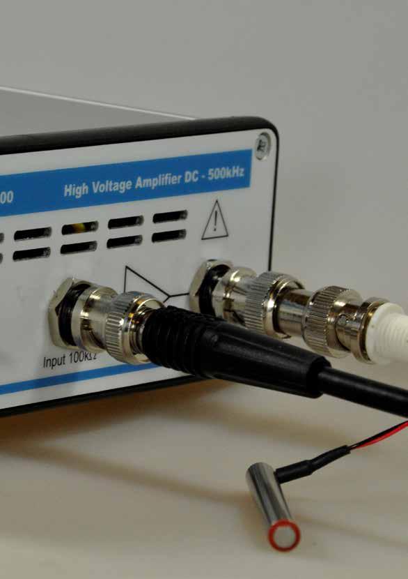
5 Detailed properties of the WMA-100 high voltage amplifier Input The input impedance of the WMA-100 high voltage amplifier is a 100kΩ resistor to ground, in parallel with 68pF to prevent electrostatic discharge (ESD) input damage. This resistor adds some noise to the output voltage unless a low-impedance source (e.g. a 50Ω output function generator) is connected to the input. The noise will be slightly higher when the amplifier input is left open. The 100kΩ resistor also adds to the output offset voltage because the offset current of the input amplifier generates a voltage over this resistor. This output offset voltage is ~10mV if the input is left open. When the input is shorted or connected to a low-impedance source, the offset is reduced to ~8mV. A high-speed amplifier like the WMA-100 model can never be made fully insensitive to input overload conditions, as this would limit the performance of the amplifier significantly. For normal operation, input voltages should remain in the 8.75V to +8.75V range, resulting, with an amplification of 20x, in an output voltage swing of 175V to +175V. Below -15V and above +15V, the input protection circuitry will limit the voltage fed to the amplifier, but the amplifier may be permanently damaged if the current of the source is not limited. Output The WMA-100 model has been designed to be fully stable with all capacitive loads. It has been optimized for a perfect step-response, but it is also a very good linear and sine-wave amplifier. The WMA-100 amplifier has a clever feedback system, which ensures that no significant overshoot occurs at any capacitive load. The bandwidth of the amplifier is automatically reduced to ensure stability. Instability under capacitive loading conditions is a common problem of other high-speed negative feedback amplifiers, often resulting in unwanted output overshoot voltages, and, in extreme cases, oscillations. Short-circuiting this amplifier will not break down the amplifier, due to the extremely fast current limiting circuit that has been employed. If output monitoring is required, it is recommended to connect a 10x oscilloscope probe to the output. A special BNC to probe tip connector is usually supplied with the probe (Fig. 1). However, the user can choose a different way of connecting the oscilloscope, as long as care is taken with the high output voltage. Using non-coaxial cable can cause overshoot in the oscilloscope reading. 5
 is lowest when a low-impedance source is used, such as a pre-amplifier output or a 50Ω function")
 and monitoring noise voltage at the output with a sensitive amplifier.")
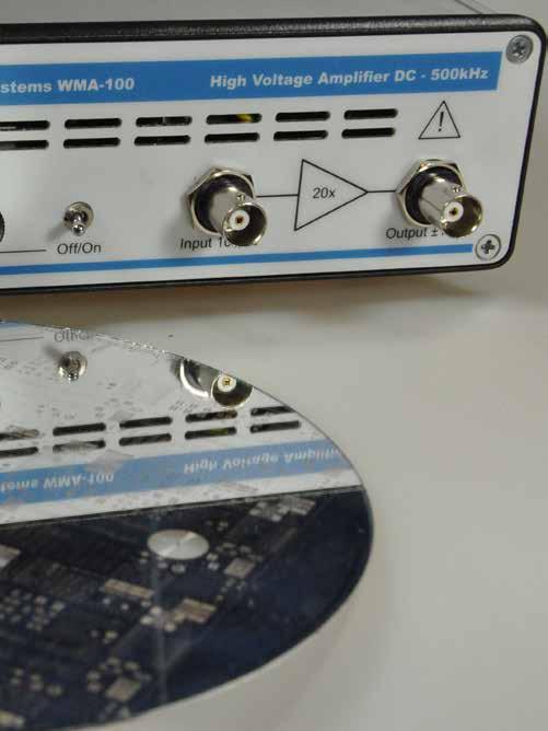
6 Falco Systems WMA-100, High Voltage Amplifier DC - 500kHz Figure 1. A 10x probe connected for monitoring the output signal Noise The noise of the amplifier (~350μVrms) is lowest when a low-impedance source is used, such as a pre-amplifier output or a 50Ω function generator output. An easy way to assess the noise performance of the amplifier without picking up interference is to connect a 50Ω coaxial load resistor to the input (Fig. 2) and monitoring noise voltage at the output with a sensitive amplifier. The output noise will be lower when the bandwidth of the amplifier is reduced, which happens when a significant capacitive load is connected to the output (see Fig. 16 for a detailed measured curve). Figure 2. If assessment of the amplifier noise is necessary, connect e.g. a 50Ω coaxial load resistor to the input to provide a low-impedance input connection. 6

7 Offset adjustment The WMA-100 model provides an offset control knob to enable the amplifier to generate offset voltages over the full output range (Fig. 3). The offset control can be switched to Off with a small rocker switch on the front panel to obtain the lowest noise and highest DC stability of the amplifier. Turning the offset control to On enables the DC control knob. The DC offset voltage reacts to adjustments of this knob in a second. With the offset control turned to On, the noise performance of the amplifier becomes slightly higher: ~600μVrms instead of ~350μVrms. Figure 3. Offset circuitry On-Off switch and offset control knob 7
8 Falco Systems WMA-100, High Voltage Amplifier DC - 500kHz The load The output impedance of the WMA-100 model is 50Ω, to ensure stability with all capacitive loads. The amplifier is generally used for high-impedance applications where the load is capacitive. This is the case for MEMS devices, EO-modulators and piezo s alike. It should be noted that a coaxial cable itself also presents a capacitive load of approximately 100pF/m. The cable that is connected may limit the maximum usable current at high frequencies. Matched loading with a 50Ω load circuit is possible by connecting a 50Ω resistor in series with the output to ground, but is not recommended. The advantage is that excessively long cables will not distort the waveforms. The disadvantage is a highly reduced voltage range (100mA in 50Ω gives 5V maximum instead of 175V maximum).with sensitive and/or high-frequency measurements, coaxial cables should be used for connecting both the input and the output, and its length should be minimized. Otherwise the cables will cause overshoot due to cable reflections (an effect related to the finite speed of light), and current limiting due to the cable capacitance. Although the amplifier itself remains fully stable, using less than 5 meter of output cable is recommended for the WMA-100 amplifier to obtain optimal results. Transmitter mode This amplifier can generate a significant amount of power at frequencies used for radio transmission and reception. The amplifier should not be used for telecommunication as described in the R&TTE directive 95/5/EC. Also for this reason always use coaxial cables. Amplifier characteristics In the following pages, several amplifier characteristics are illustrated: Frequency response as a function of capacitive load (Fig. 4, 5) Sine and triangle wave responses (Fig. 6, 7) Square wave response (Fig. 8, 9, 10) Step response (Fig. 11) Capacitive load dependency of square wave output (Fig. 12) Noise and offset with and without offset control engaged (Fig. 13, 14) Noise spectrum (Fig. 15) Rms output noise voltage versus capacitive load (Fig. 16) 8
9
10 Falco Systems WMA-100, High Voltage Amplifier DC - 500kHz Figure 4. Frequency response at 300Vpp output voltage with different capacitive loads Figure 5. Frequency response at 1Vpp output voltage with different capacitive loads 10
11 Figure 6. Sine wave 300Vpp 1kHz Figure 7. Triangle wave 300Vpp 1kHz 11
12 Falco Systems WMA-100, High Voltage Amplifier DC - 500kHz Figure 8. Square wave 300Vpp 1kHz Figure 9. Square wave 300Vpp 100kHz 12
13 Figure 10. Square wave 1Vpp 100kHz (small signal response) Figure 11a. 300Vpp step response 10-90%: up in 1.0μs 13

14 Falco Systems WMA-100, High Voltage Amplifier DC - 500kHz 14
15 15
16 Falco Systems WMA-100, High Voltage Amplifier DC - 500kHz Figure 11b. 300Vpp step response 10-90%: down in 0.9μs Figure 11c. 0 to 150V step response 10-90%: up in 0.8μs 16
17 Figure 11d V step response 10-90%: down in 0.8μs Figure 12a. 0pF load 17
18 Falco Systems WMA-100, High Voltage Amplifier DC - 500kHz Figure 12b. 100pF load Figure 12c. 1nF load 18
19 Figure 12d. 10nF load Figure 12e. 100nF load 19
20 Falco Systems WMA-100, High Voltage Amplifier DC - 500kHz Figure 12f. 1μF load Figure 12g. 10μF load Figure Vpp square wave response under different capacitive loading conditions. The 100mA current limit limits the speed at which the capacitor can be charged.the bandwidth adjustments of the amplifier with different capacitive loads preventing overshoot are clearly visible. Note the difference of the horizontal timescale in the figures. 20
 and typical offset with the offset control switched")

21 Figure 13. Noise (~350μVrms measured with a true rms voltmeter) and typical offset with the offset control switched to Off. The noise and offset may appear to be higher than shown here if the amplifier input is not connected to a lowimpedance source. Figure 14. Noise (~600μVrms measured with a true rms voltmeter) with the offset control switched to On. In addition, the short term drift of the offset is around 5mV. 21
22 Falco Systems WMA-100, High Voltage Amplifier DC - 500kHz Figure 15. Noise spectrum ( bins 15MHz FFT) with offset control switched to Off. Figure 16. Rms output noise voltage versus capacitive load with offset control switched to Off. 22
23 Technical specifications Amplification : 20x, fixed Bandwidth : DC - -3dB large signal bandwidth Slew rate : 350V/μs typical Output voltage : -175V to +175V Current : 100mA typical with limiter Noise and offset : 350μVrms output noise typical, 8mV offset typical Input impedance : 100kΩ Output impedance : 50Ω Stability : stable with all capacitive and resistive loads, no overshoot > 5% Power : 230V 50Hz AC, 50W or 115V 60 Hz AC, 50W Mains fuse : 2x 0.25A 250V slow blow (230V version) or 2x 0.5A 250V slow blow (115V version) Safety : Class I - requires mains power connector with protective earth Overvoltage : Category II Operating temperature : C Storage temperature : 0-60 C Relative humidity : 30-70% non-condensing Maximum usage height : 2000m Dimensions : 52 x 165 x 220 mm Weight : 2.5 kg Country of origin : The Netherlands Specifications may be subject to change Harmonized standards This product complies with the following harmonized European standards: Safety : EN EMC : EN61326 WEEE and RoHS Do not dispose of the WMA-100 amplifier as standard waste, but bring it to a WEEE electronic waste collection point. The amplifier has been built in compliance with the RoHS directive. 23

24 Falco Systems WMA-100, High Voltage Amplifier DC - 500kHz 24
25 25
26 Warranty Falco Systems products are guaranteed against malfunction due to defects in materials or workmanship for a period of 1 year from the date of shipment. If a malfunction occurs during this period, the product will be repaired or replaced without charge. The product will be returned to the customer prepaid. The warranty does not apply to: Exterior finish or appearance Malfunction resulting from use or operation of the product in other ways than specified in the user manual Malfunctioning due to misuse or abuse of the product Malfunctioning occurring after changes or repairs have been made by anyone other than Falco Systems. To obtain warranty service, the customer has to inform Falco Systems first via info@falco-systems.com to receive further instructions. Falco Systems will not be liable for any consequential damages, including, without limitation, devices or equipment connected to the product, injury to persons or property or loss of use. See for more details the Falco Systems Standard Terms and Conditions of Sale, which can also be obtained via info@falco-systems.com.
27
28 Falco Systems WMA-100, High Voltage Amplifier DC - 500kHz User manual version 2.1 March
USER MANUAL. Ultra-Low Noise High Voltage Amplifier WMA V to +150V output. 300µV rms output noise. 2mV output offset voltage
 Ultra-Low Noise High Voltage Amplifier WMA-28 280 www.falco falco-systems systems.com USER MANUAL -150V to +150V output 300µV rms output noise 2mV output offset voltage ±300mA Output current limit DC to
USER MANUAL. DC - 5MHz High Voltage Amplifier WMA V to +100V output. DC to -3dB large signal bandwidth. 1300V/µs slew rate typical
 DC - 5MHz High Voltage Amplifier WMA-320 www.falco-systems.com USER MANUAL -0V to +0V output DC to 5MHz @ -3dB large signal bandwidth 1300V/µs slew rate typical ±300mA Output current limit Stable with
USER MANUAL. DC 13kHz High Voltage Amplifier WMA V to +175V output. Stable with all capacitive loads, generates no overshoot
 DC 13kHz High Voltage Amplifier WMA-02 www.falco falco-systems systems.com USER MANUAL -175V to +175V output DC to 13kHz at -3dB full power bandwidth single power supply 24V 30V DC, battery power possible
DUAL CHANNEL BROADBAND LINEAR AMPLIFIER Model A800D
 DUAL CHANNEL BROADBAND LINEAR AMPLIFIER Model A800D HIGH VOLTAGE FIXED GAIN BROADBAND 800Vpp 60mA 100x DC to ca 200 khz LOW OUTPUT IMPEDANCE HIGH SLEW RATE
High voltage amplifiers: how fast are they really? Falco Systems application note, version 2.0,
 Application note High voltage amplifiers: how fast are they really? Falco Systems application note, version., www.falco-systems.com W. Merlijn van Spengen, PhD March 1 The high speed, high voltage amplifier:
BROADBAND LINEAR AMPLIFIER Model F1020 (models F10A and F20A combined)
") BROADBAND LINEAR AMPLIFIER Model F1020 (models F10A and F20A combined) HIGH VOLTAGE FIXED GAIN BROADBAND ±100V 185mA/±150V 150mA 10x/20x DC to ca 1 MHz HIGH SLEW RATE LOW OUTPUT IMPEDANCE 300 V/µs
BROADBAND LINEAR AMPLIFIER Model F1020 (models F10A and F20A combined) HIGH VOLTAGE FIXED GAIN BROADBAND ±100V 185mA/±150V 150mA 10x/20x DC to ca 1 MHz HIGH SLEW RATE LOW OUTPUT IMPEDANCE 300 V/µs
DUAL%CHANNEL%LINEAR%AMPLIFIER %WITH%PHASE%INVERTER Model&A400DI
 ELECTRONICS AB DUAL%CHANNEL%LINEAR%AMPLIFIER %WITH%PHASE%INVERTER ModelA400DI HIGHVOLTAGE FIXEDGAIN BROADBAND ±200V 150mA 20x DCtoca500kHz FULLSCALE LOWOUTPUTIMPEDANCE HIGHSLEWRATE
BROADBAND'LINEAR'AMPLIFIER WITH'A±B'INPUTS'AND'DC5OFFSET Model&A400X
 ELECTRONICS AB BROADBAND'LINEAR'AMPLIFIER WITH'A±B'INPUTS'AND'DC5OFFSET ModelA400X HIGHVOLTAGE FIXEDGAIN BROADBAND ±200V 150mA 20x DCtoca500kHz FULLSCALE LOWOUTPUTIMPEDANCE HIGHSLEWRATE
TETRIS User's Guide. High Impedance Active Probe DO177-1
 TETRIS 1500 High Impedance Active Probe User's Guide DO177-1 TETRIS 1500 Copyright 2010 Ltd. All rights reserved. Information in this publication supersedes that in all previously published material. Specifications
BROADBAND'LINEAR'AMPLIFIER Model&F10AD
 BROADBAND'LINEAR'AMPLIFIER Model&F10AD DUAL'CHANNEL & HIGH&VOLTAGE& FIXED&GAIN& BROADBAND & ±100V&185mA& 10x& DC&to&ca&1&MHz & HIGH&SLEW&RATE& LOW&OUTPUT&IMPEDANCE & 400&V/µs&
TETRIS 1000 High Impedance Active Probe. Instruction Manual
 TETRIS 1000 High Impedance Active Probe Instruction Manual Copyright 2015 PMK GmbH All rights reserved. Information in this publication supersedes that in all previously published material. Specifications
BROADBAND LINEAR AMPLIFIER Model P150
 ELECTRONICS AB BROADBAND LINEAR AMPLIFIER Model P150 HIGH VOLTAGE GAIN HIGH CURRENT +150V 20x 1A HIGH POWER SMALL SIGNAL SLEW RATE BANDWIDTH BANDWIDTH 30 V/µs DC to ca 60 khz DC to >200 khz FLC Electronics
PKT 512A-RO High Impedance Passive Cable Divider
 PKT 512A-RO High Impedance Passive Cable Divider Instruction Manual Copyright 2011 PMK GmbH All rights reserved. Information in this publication supersedes that in all previously published material. Specifications
TA MHz oscilloscope probe TA MHz oscilloscope probe
 TA375 100 MHz oscilloscope probe TA386 200 MHz oscilloscope probe User's Guide X1 X10 TA386 X1/X10 Max. 600 Vp Introduction This passive high-impedance oscilloscope probe is suitable for most oscilloscopes
PHV RO High Voltage Passive Probe. Instruction Manual
 PHV 1000-3-RO High Voltage Passive Probe Instruction Manual Copyright 2012 PMK GmbH All rights reserved. Information in this publication supersedes that in all previously published material. Specifications
400 MHz Passive High-Voltage Probe R&S RT-ZH
 Manual 400 MHz Passive High-Voltage Probe R&S RT-ZH11 1409.7737.02 Printed in Germany Test and Measurment Manufacturer ROHDE & SCHWARZ For comprehensive information about Rohde and Schwarz, please visit
Operator s Manual. PP017 and PP018 Passive Probes
 Operator s Manual PP017 and PP018 Passive Probes 700 Chestnut Ridge Road Chestnut Ridge, NY, 10977-6499 Tel: (845) 425-2000, Fax: (845) 578 5985 teledynelecroy.com PP017 and PP018 Passive Probes Operator
PHV 1000-RO High Voltage Passive Probe. Instruction Manual
 PHV 1000-RO High Voltage Passive Probe Instruction Manual Copyright 2014 PMK GmbH All rights reserved. Information in this publication supersedes that in all previously published material. Specifications
Experiment 1: Instrument Familiarization (8/28/06)
") Electrical Measurement Issues Experiment 1: Instrument Familiarization (8/28/06) Electrical measurements are only as meaningful as the quality of the measurement techniques and the instrumentation applied
Electrical Measurement Issues Experiment 1: Instrument Familiarization (8/28/06) Electrical measurements are only as meaningful as the quality of the measurement techniques and the instrumentation applied
Operator s Manual. PP022 Passive Probe
 Operator s Manual PP022 Passive Probe 700 Chestnut Ridge Road Chestnut Ridge, NY, 10977-6499 Tel: (845) 425-2000, Fax: (845) 578 5985 teledynelecroy.com PP022 Passive Probe Instruction Manual 2017 Teledyne
DM-45 Digital Multimeter
 INSTRUCTION MANUAL DM-45 Digital Multimeter Read and understand all of the instructions and safety information in this manual before operating or servicing this tool. Description The Greenlee DM-45 Digital
Tabor Electronics Signal Amplifiers. Quick Start Guide
 Tabor Electronics Signal Amplifiers Quick Start Guide Tabor Signal Amplifiers- Quick Start Guide - FAQ No. 0309757 Introduction Amplification is an increase in size of a signal by some factor which is
supplies and frequency converters. BumbleBee is also very effective in fast transient measurements
 High Voltage Differential Probe Order-No: 880-102-501 Features: 1000 V CAT III 400 MHz Bandwidth < 1 % Deviation within Specified Operating Temperatures (0 C to +50 C) High CMRR 4 Mode Attenuation Useable
Experiment 1: Instrument Familiarization
 Electrical Measurement Issues Experiment 1: Instrument Familiarization Electrical measurements are only as meaningful as the quality of the measurement techniques and the instrumentation applied to the
ProfiScale MULTI Multimeter
 1,5 V 9V 200 mv 600 V 200 ma 1/10 A ProfiScale MULTI Multimeter en Operating instructions BURG-WÄCHTER KG Altenhofer Weg 15 58300 Wetter Germany Introduction Want the reassurance of knowing whether current
The table below lists the symbols used on the Clamp and/or in this manual. Important Information. See manual.
 i310s AC/DC Current Clamp Instruction Sheet Introduction The i310s Current Clamp ( Clamp ) has been designed for use with oscilloscopes and digital multimeters for accurate nonintrusive measurement of
3B SCIENTIFIC PHYSICS
 3B SCIENTIFIC PHYSICS Analogue Multimeter Escola 100 1013527 Instruction sheet 12/15 SD/JS 1 Display with mirror scale 2 Slotted screw for zero calibration 3 Calibration trimmer for setting centre zero
Operator s Manual. PP016 Passive Probe
 Operator s Manual PP016 Passive Probe 2017 Teledyne LeCroy, Inc. All rights reserved. Unauthorized duplication of Teledyne LeCroy documentation materials is strictly prohibited. Customers are permitted
PHYS 536 The Golden Rules of Op Amps. Characteristics of an Ideal Op Amp
 PHYS 536 The Golden Rules of Op Amps Introduction The purpose of this experiment is to illustrate the golden rules of negative feedback for a variety of circuits. These concepts permit you to create and
AC/DC Current Oscilloscope Probe Model SL261
 AC/DC Current Oscilloscope Probe Model SL261 USER MANUAL I ZERO 100 mv/a 10 mv/a OFF Statement of Compliance Chauvin Arnoux, Inc. d.b.a. AEMC Instruments certifies that this instrument has been calibrated
DDS Function Generator
 Model: 4007B, 4013B DDS Function Generator USER MANUAL Safety Summary The following safety precautions apply to both operating and maintenance personnel and must be observed during all phases of operation,
IDEAL INDUSTRIES, INC. TECHNICAL MANUAL MODEL: MODEL: Multimeter Service Information
 IDEAL INDUSTRIES, INC. TECHNICAL MANUAL MODEL: 61-340 MODEL: 61-342 Multimeter Service Information The Service Information provides the following information: Precautions and safety information Specifications
CIRCUIT-TEST ELECTRONICS
 USER'S MANUAL Sweep Function Generator with Counter SWF-8030 CIRCUIT-TEST ELECTRONICS www.circuittest.com TABLE OF CONTENTS SAFETY INFORMATION...page 3 INTRODUCTION... 4 SPECIFICATIONS... 5 FRONT PANEL
Four-Channel Differential AC Amplifier
 Four-Channel Differential AC Amplifier INSTRUCTION MANUAL FOR HIGH-GAIN DIFFERENTIAL AMPLIFIER MODEL 1700 Serial # Date A-M Systems, Inc. PO Box 850 Carlsborg, WA 98324 U.S.A. 360-683-8300 800-426-1306
Thank you again for choosing AstroAI, if you have any questions or concerns regarding your product, please contact us at
 ASTROAI USER MANUAL DT132A 4000 Count Auto-Ranging Multimeter Thank you for purchasing the AstroAI DT132A 4000 Count Auto-Ranging Multimeter. It is a 3 ¾ digit, 3999 counts, auto-ranging digital multimeter.
IDEAL INDUSTRIES, INC. TECHNICAL MANUAL MODEL:
 IDEAL INDUSTRIES, INC. TECHNICAL MANUAL MODEL: 61-352 The Service Information provides the following information: Precautions and safety information Specifications Basic maintenance (cleaning, replacing
Power Amplifier. Input Characteristics. SPECIFICATIONS NI PXIe-4610 Power Amplifier. Signal Range
 SPECIFICATIONS NI PXIe-4610 Power Amplifier This document lists specifications for the NI PXIe-4610 Power Amplifier. These specifications are typical at 25 ºC unless otherwise stated. The operating range
Single Supply, Rail to Rail Low Power FET-Input Op Amp AD820
 a FEATURES True Single Supply Operation Output Swings Rail-to-Rail Input Voltage Range Extends Below Ground Single Supply Capability from + V to + V Dual Supply Capability from. V to 8 V Excellent Load
ECE 2274 Lab 2. Your calculator will have a setting that will automatically generate the correct format.
 ECE 2274 Lab 2 Forward (DO NOT TURN IN) You are expected to use engineering exponents for all answers (p,n,µ,m, N/A, k, M, G) and to give each with a precision between one and three leading digits and
Advanced Test Equipment Rentals ATEC (2832)
") Established 1981 Advanced Test Equipment Rentals www.atecorp.com 800-404-ATEC (2832) A.H. Systems Model Active Monopole Antennas Active Monopole Antenna Series Operation Manual 1 TABLE OF CONTENTS INTRODUCTION
Established 1981 Advanced Test Equipment Rentals www.atecorp.com 800-404-ATEC (2832) A.H. Systems Model Active Monopole Antennas Active Monopole Antenna Series Operation Manual 1 TABLE OF CONTENTS INTRODUCTION
INSTRUCTION MANUAL MODEL 4010A. 2 MHz FUNCTION GENERATOR MANUAL DE INSTRUCCIONES MODELO 4010A. 2MHz GENERADOR DE FUNCIONES
 INSTRUCTION MANUAL MANUAL DE INSTRUCCIONES MODEL 4010A MODELO 4010A 2 MHz FUNCTION GENERATOR 2MHz GENERADOR DE FUNCIONES TEST INSTRUMENT SAFETY WARNING Normal use of test equipment exposes you to a certain
PD32-32 Channel Piezo Driver Manual and Specifications
 PD32-32 Channel Piezo Driver Manual and Specifications PiezoDrive Pty. Ltd. www.piezodrive.com Contents 1 Introduction... 3 2 Warnings / Notes... 3 3 Specifications... 4 4 Output Voltage Range... 5 4.1
USER'S MANUAL ACDC-100 TRMS ACDC-100. Versatile AC/DC Clamp-on Multimeter Series
 99 Washington Street Melrose, MA 02176 Fax 781-665-0780 TestEquipmentDepot.com USER'S MANUAL ACDC-100 TRMS ACDC-100 Versatile AC/DC Clamp-on Multimeter Series 1 1) SAFETY This manual contains information
NOTE: Fully read and understand this manual before using this Digital Multimeter.
 ASTROAI USER MANUAL AUTO RANGING DIGITAL CLAMP METER Thank you for purchasing the Auto Ranging Digital Clamp Meter from AstroAI. The AstroAI Auto Ranging Digital Clamp Meter is designed to be safely and
Q44/Q66 PROFESSIONAL AMPLIFIER OWNER S MANUAL
 Q44/Q66 PROFESSIONAL AMPLIFIER OWNER S MANUAL IMPORTANT SAFETY INSTRUCTIONS The lightning flash with arrowhead symbol, within an equilateral triangle is intended to alert the user to the presence of uninsulated
Sampling and Reconstruction
 Experiment 10 Sampling and Reconstruction In this experiment we shall learn how an analog signal can be sampled in the time domain and then how the same samples can be used to reconstruct the original
Handheld Digital Multimeter PRO-50A
 Handheld Digital Multimeter PRO-50A Safety Summary A statement calls attention to an operating procedure, practice, or condition, which, if not followed correctly, could result in injury or death to personnel.
Model 4007DDS. 7 MHz Sweep Function Generator
 Model 4007DDS 7 MHz Sweep Function Generator 1 Model 4007DDS - Instruction Manual Limited Two-Year Warranty B&K Precision warrants to the original purchaser that its products and the component parts thereof,
TT-SI MHz Active Differential Probe
 INSTRUCTION MANUAL TT-SI 9110 100MHz Active Differential Probe These probe is in compliance with EN61010-031:2002+A1:2008 CAT III, Pollution Degree 2 1. Safety Terms and Symbols Terms appear in this manual:
Single Supply, Rail to Rail Low Power FET-Input Op Amp AD820
 a FEATURES True Single Supply Operation Output Swings Rail-to-Rail Input Voltage Range Extends Below Ground Single Supply Capability from V to V Dual Supply Capability from. V to 8 V Excellent Load Drive
Appendix A: Specifications
 All specifications apply to the TDS 200-Series Digital Oscilloscopes and a P2100 probe with the Attenuation switch set to 10X unless noted otherwise. To meet specifications, two conditions must first be
TD250 6 Channel 250V Amplifier Manual and Specifications
 TD250 6 Channel 250V Amplifier Manual and Specifications PiezoDrive Pty. Ltd. www.piezodrive.com 1 Contents 1 Introduction... 3 2 Warnings / Notes... 3 3 Specifications... 4 4 Channel Configuration...
RIGOL. User s Guide. RP1000D Series High Voltage Differential Probe. Feb RIGOL Technologies, Inc
 User s Guide RP1000D Series High Voltage Differential Probe Feb. 2013 RIGOL Technologies, Inc Guaranty and Declaration Copyright 2012 RIGOL Technologies, Inc. All Rights Reserved. Trademark Information
EC Declaration of Conformity
 EC Declaration of Conformity TABLE OF CONTENTS 1. SAFETY SUMMARY.. 1 2. INTRODUCTION 5 3. SPECIFICATION 7 EN 61326-1: Electrical equipment for measurement, control and laboratory use EMC requirements (1997+A1:
TK 100 Probe Calibrator. Instruction Manual
 TK 100 Probe Calibrator Instruction Manual Copyright 2013 PMK GmbH All rights reserved. Information in this publication supersedes that in all previously published material. Specifications are subject
High voltage amplifiers and the ubiquitous 50 Ohm: Caveats and benefits. Falco Systems application note, version 1.0,
 Application note High voltage amplifiers and the ubiquitous Ohm: Caveats and benefits Falco Systems application note, version 1., www.falco-systems.com W. Merlijn van Spengen, PhD September 217 Wait, my
LM6118/LM6218 Fast Settling Dual Operational Amplifiers
 Fast Settling Dual Operational Amplifiers General Description The LM6118/LM6218 are monolithic fast-settling unity-gain-compensated dual operational amplifiers with ±20 ma output drive capability. The
RIGOL Data Sheet. DG3000 Series Function/Arbitrary Waveform Generator DG3121A, DG3101A, DG3061A. Product Overview. Easy to Use Design.
 RIGOL Data Sheet DG3000 Series Function/Arbitrary Waveform Generator DG3121A, DG3101A, DG3061A Product Overview DG3000 Series Function/Arbitrary Waveform Generators adopt DDS technology, which enables
Dawson DDM181. Pocket-Size Autorange Digital Meter User s Manual
 Dawson DDM181 Pocket-Size Autorange Digital Meter User s Manual 1 Table of Contents LIMITED WARRANTY AND LIMITATION OF LIABILITY... 3 Out of the Box... 3 Accessories... 4 Important Safety Information...
User Manual Digital Multimeter
 User Manual Digital Multimeter model no.: MSR-R500 Questions or Concerns? support@etekcity.com visit etekcity.com for more products Safe and Proper Usage Thank you for purchasing the Etekcity MSR-R500
AC/DC Current Probe GCP-100 QUICK START GUIDE ISO-9001 CERTIFIED MANUFACTURER
 AC/DC Current Probe GCP-100 QUICK START GUIDE ISO-9001 CERTIFIED MANUFACTURER This manual contains proprietary information, which is protected by copyright. All rights are reserved. No part of this manual
High Speed BUFFER AMPLIFIER
 High Speed BUFFER AMPLIFIER FEATURES WIDE BANDWIDTH: MHz HIGH SLEW RATE: V/µs HIGH OUTPUT CURRENT: 1mA LOW OFFSET VOLTAGE: 1.mV REPLACES HA-33 IMPROVED PERFORMANCE/PRICE: LH33, LTC11, HS APPLICATIONS OP
Digital Function Generator
 Digital Function Generator 13654-99 PHYWE Systeme GmbH & Co. KG Robert-Bosch-Breite 10 37079 Göttingen Germany Tel. +49 (0) 551 604-0 Fax +49 (0) 551 604-107 E-mail info@phywe.de Operating Instructions
HA MHz, High Slew Rate, High Output Current Buffer. Description. Features. Applications. Ordering Information. Pinouts.
 SEMICONDUCTOR HA-2 November 99 Features Voltage Gain...............................99 High Input Impedance.................... kω Low Output Impedance....................... Ω Very High Slew Rate....................
MHz FUNCTION GENERATOR INSTRUCTION MANUAL
 72-6859 20MHz FUNCTION GENERATOR INSTRUCTION MANUAL Table of Contents Introduction 2 Specification 2 EMC 5 Safety 4 Installation 5 Operation 7 Maintenance 8 www.tenma.com 1 Introduction This instrument
HA-2520, HA-2522, HA-2525
 HA-, HA-, HA- Data Sheet September 99 File Number 9. MHz, High Slew Rate, Uncompensated, High Input Impedance, Operational Amplifiers HA-// comprise a series of operational amplifiers delivering an unsurpassed
EPA152/252/502. User Manual.
 EPA152/252/502 User Manual www.audac.eu ADDITIONAL INFORMATION This manual is put together with much care, and is as complete as could be on the publication date. However, updates on the specifications,
DECLARATION OF CONFORMITY
 DECLARATION OF CONFORMITY Manufacturer's Name: Transmille Ltd. Manufacturer's Address: Unit 4, Select Business Centre Lodge Road Staplehurst TN12 0QW. United Kingdom. Declares, that the product Product
ECE 2274 Lab 2 (Network Theorems)
") ECE 2274 Lab 2 (Network Theorems) Forward (DO NOT TURN IN) You are expected to use engineering exponents for all answers (p,n,µ,m, N/A, k, M, G) and to give each with a precision between one and three
ECE 2274 Lab 2 (Network Theorems) Forward (DO NOT TURN IN) You are expected to use engineering exponents for all answers (p,n,µ,m, N/A, k, M, G) and to give each with a precision between one and three
Model 7000 Low Noise Differential Preamplifier
 Model 7000 Low Noise Differential Preamplifier Operating Manual Service and Warranty Krohn-Hite Instruments are designed and manufactured in accordance with sound engineering practices and should give
79/26 Series III Multimeter
 79/26 Series III Multimeter Instruction Sheet W Read First: Safety Information Never use the meter if the meter or test leads look damaged. Be sure the test leads and switch are in the correct position
Manual Supplement. This supplement contains information necessary to ensure the accuracy of the above manual.
 Manual Title: 5502E Getting Started Supplement Issue: 3 Part Number: 4155211 Issue Date: 9/18 Print Date: November 2012 Page Count: 12 Revision/Date: This supplement contains information necessary to ensure
INSTRUCTION MANUAL ACD-10 PRO & TRMS PRO
 INSTRUCTION MANUAL ACD-10 PRO & TRMS PRO AMPROBE 1 Congratulations! You are now the owner of an AMPROBE Instrument. It has been quality crafted according to quality standards and contains quality components
User s Guide. 400A AC/DC Clamp Meter. Model MA220
 User s Guide 400A AC/DC Clamp Meter Model MA220 Introduction Thank you for selecting the Extech MA200 AC/DC Clamp Meter. This meter measures AC/DC Current, AC/DC Voltage, Resistance, Capacitance, Frequency,
5500A. Multi-Product Calibrator. Extended Specifications 2005
 5500A Multi-Product Calibrator Extended Specifications 2005 5500A Specifications The following paragraphs detail specifications for the 5500A Calibrator. The specifications are valid after allowing a warm-up
TA MHz ±30 V Differential Probe User s Manual. This probe complies with IEC , IEC CAT I, Pollution Degree 2.
 TA046 800 MHz ±30 V Differential Probe User s Manual This probe complies with IEC-1010.1, IEC-1010.2-031 CAT I, Pollution Degree 2. 1. Safety terms and symbols Terms appearing in this manual: WARNING Warning
N acquisitions, all channels simultaneously, N is selectable from 4, 16, 64, and 128 Inputs
 With compliments All specifications apply to the TDS 200-Series Digital Real-Time Oscilloscope with a P2100 probe with the Attenuation switch set to 10X unless noted otherwise. To meet specifications,
MODEL W Power Amplifier
 TEGAM, INC. MODEL 2348 18.75 W Power Amplifier This owner s manual was as current as possible when this product was manufactured. However, products are constantly being updated and improved. Because of
RIGOL Data Sheet. DG2000 Series Function/Arbitrary Waveform Generator DG2041A, DG2021A. Product Overview. Main Features.
 RIGOL Data Sheet DG2000 Series Function/Arbitrary Waveform Generator DG2041A, DG2021A Product Overview DG2000 Series Function/Arbitrary Waveform Generators adopt DDS technology, which enables to generate
Fluke 83V and 87V Digital Multimeters
 Fluke 83V and 87V Digital Multimeters Detailed Specifications For all detailed specifications: is given as ±([% of reading] + [number of least significant digits]) at 18 C to 28 C, with relative humidity
6500V/µs, Wideband, High-Output-Current, Single- Ended-to-Differential Line Drivers with Enable
 99 Rev ; /99 EVALUATION KIT AVAILABLE 65V/µs, Wideband, High-Output-Current, Single- General Description The // single-ended-todifferential line drivers are designed for high-speed communications. Using
ULTRA HIGH VOLTAGE DUAL OPERATIONAL AMPLIFIER
 MILPRF8 CERTIFIED M.S.KENNEDY CORP. 6 707 Dey Road Liverpool, N.Y. 088 () 7067 FEATURES: Internally Compensated For Gains > 0 V/V Monolithic MOS Technology High Voltage Operation : 0V Low Quiescent Current
PLL Synchronizer User s Manual / Version 1.0.6
 PLL Synchronizer User s Manual / Version 1.0.6 AccTec B.V. Den Dolech 2 5612 AZ Eindhoven The Netherlands phone +31 (0) 40-2474321 / 4048 e-mail AccTecBV@tue.nl Contents 1 Introduction... 3 2 Technical
Dawson DDM230C. True RMS Multimeter with Bar Graph Display User s Manual
 Dawson DDM230C True RMS Multimeter with Bar Graph Display User s Manual Table of Contents LIMITED WARRANTY AND LIMITATION OF LIABILITY... 3 Out of the Box... 3 Accessories... 4 Safety Information... 4
Test No. 1. Introduction to Scope Measurements. Report History. University of Applied Sciences Hamburg. Last chance!! EEL2 No 1
 University of Applied Sciences Hamburg Group No : DEPARTMENT OF INFORMATION ENGINEERING Laboratory for Instrumentation and Measurement L: in charge of the report Test No. Date: Assistant A2: Professor:
GF 467F FUNCTION GENERATOR. PROTECTED RS232 + (USB OR LAN)* LabVIEW 0,01 Hz to 5 MHz CMos. Specifications. Other specifications
* LabVIEW 0,01 Hz to 5 MHz CMos. Specifications. Other specifications") FUNCTION GENERATOR EAN CODE : 3760244880468 5 MHZ+RS232++(USB or LAN)* GF 467F COMPLETE : Reciprocal frequency counter 50 MHz. - Internal linear or logarithmic sweep, and external VCF or FM modulation.
FUNCTION GENERATOR EAN CODE : 3760244880468 5 MHZ+RS232++(USB or LAN)* GF 467F COMPLETE : Reciprocal frequency counter 50 MHz. - Internal linear or logarithmic sweep, and external VCF or FM modulation.
8120 FUNCTION GENERATOR Operation Manual
 8120 FUNCTION GENERATOR Operation Manual Copyright Copyright 1996 by this company. All rights reserved. No part of this publication may be reproduced in any form or by any means without the written permission
MiniFlex MF MF FLEXIBLE AC CURRENT SENSOR. User Manual
 FLEXIBLE AC CURRENT SENSOR MiniFlex MF 300-6-2-10 MF 3000-10-2-1 E N G L I S H User Manual Statement of Compliance Chauvin Arnoux, Inc. d.b.a. AEMC Instruments certifies that this instrument has been calibrated
LM4562 Dual High Performance, High Fidelity Audio Operational Amplifier
 Dual High Performance, High Fidelity Audio Operational Amplifier General Description The is part of the ultra-low distortion, low noise, high slew rate operational amplifier series optimized and fully
Model Operating Manual
 Model 7500 DC to 1MHz Wideband Power Amplifier Operating Manual Copyright 2004. All rights reserved. Contents of this publication may not be reproduced in any form without the written permission of Krohn-Hite
WHALETEQ. ESU Neutral Electrodes Impedance Tester. Model: HFPA150. User Manual
 WHALETEQ ESU Neutral Electrodes Impedance Tester Model: HFPA150 User Manual Version2014-10-30 Hardware Version1.3.x 1. Introduction HFPA150 is a unique tester specifically designed for the testing of neutral
HA-2600, HA Features. 12MHz, High Input Impedance Operational Amplifiers. Applications. Pinouts. Ordering Information
 HA26, HA26 September 998 File Number 292.3 2MHz, High Input Impedance Operational Amplifiers HA26/26 are internally compensated bipolar operational amplifiers that feature very high input impedance (MΩ,
MODEL 9050 EXTENDED SPECIFICATIONS. 50ppm TRANSPORTABLE CALIBRATOR
 MODEL 9050 EXTENDED SPECIFICATIONS Ü 50ppm TRANSPORTABLE CALIBRATOR 9050A EXTENDED SPECIFICATIONS General Specifications TRANSMILLE LTD Warm Up Time Double the time since last used up to 20 minutes maximum
DVM98. True RMS Digital Multimeter. 1 Safety information. 1.1 Preliminary. 1.2 During use
 True RMS Digital Multimeter DVM98 1 Safety information This multimeter has been designed according to IEC - 1010 concerning electronic measuring instruments with an overvoltage category (CAT II) and pollution
DVM1190 DIGITAL MULTIMETER
 DIGITAL MULTIMETER 1. Introduction Thank you for buying the. This digital multimeter has a large LCD, a data-hold function and a backlight. The device uses a very practical safety mechanism that keeps
PDu150CL Ultra-low Noise 150V Piezo Driver with Strain Gauge Feedback
 PDu1CL Ultra-low Noise 1V Piezo Driver with Strain auge Feedback The PDu1CL combines a miniature high-voltage power supply, precision strain conditioning circuit, feedback controller, and ultra-low noise
High Power Monolithic OPERATIONAL AMPLIFIER
 High Power Monolithic OPERATIONAL AMPLIFIER FEATURES POWER SUPPLIES TO ±0V OUTPUT CURRENT TO 0A PEAK PROGRAMMABLE CURRENT LIMIT INDUSTRY-STANDARD PIN OUT FET INPUT TO- AND LOW-COST POWER PLASTIC PACKAGES
PHV RO. High impedance passive probe. Features: CeramCore TM Hybrid Probe. Modular Construction. Coaxial Design
 High impedance passive probe Features: CeramCore TM Hybrid Probe Modular Construction Coaxial Design Interchangeable Spring Contact Tip Certificate of Calibration available on request Read-out BNC Connector
HA-2520, HA MHz, High Slew Rate, Uncompensated, High Input Impedance, Operational Amplifiers. Features. Applications. Ordering Information
 HA-22, HA-22 Data Sheet August, 2 FN2894. 2MHz, High Slew Rate, Uncompensated, High Input Impedance, Operational Amplifiers HA-22/22 comprise a series of operational amplifiers delivering an unsurpassed
EPA104/254. User Manual.
 EPA104/254 User Manual www.audac.eu ADDITIONAL INFORMATION This manual is put together with much care, and is as complete as could be on the publication date. However, updates on the specifications, functionality