Resonance. Resonance curve.
|
|
|
- Cora Washington
- 5 years ago
- Views:
Transcription

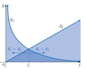
1 Resonance This chapter will introduce the very important resonant (or tuned) circuit, which is fundamental to the operation of a wide variety of electrical and electronic systems in use today. The resonant circuit is a combination of R, L, and C elements having a frequency response characteristic similar to the one appearing in Figure. Resonance curve.
, the internal resistance of the inductor (Rl), and any added resistance to")
2 1. SERIES RESONANCE CIRCUIT A resonant circuit (series or parallel) must have an inductive and a capacitive element. A resistive element will always be present due to the internal resistance of the source (Rs), the internal resistance of the inductor (Rl), and any added resistance to control the shape of the response curve (Rdesign ).

3 The total impedance of this network at any frequency is determined by The resonant conditions described in the introduction will occur when The total impedance at resonance is then simply representing the minimum value of ZT at any frequency. The subscript s will be employed to indicate series resonant conditions. Substituting yields
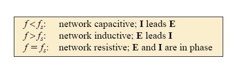
4 The current through the circuit at resonance is maximum current which you will note is the maximum current for the circuit of Figure for an applied voltage E since ZT is a minimum value. the input voltage and current are in phase at resonance. and, since XL = XC, the magnitude of VL equals VC at resonance; that is,
5 A phasor diagram of the voltages and current, clearly indicates that the voltage across the resistor at resonance is the input voltage, and E, and I, and VR are in phase at resonance. The power triangle at resonance shows that the total apparent power is equal to the average power dissipated by the resistor since QL = QC. The power factor of the circuit at resonance is
6 THE QUALITY FACTOR (Q ) The quality factor Q of a series resonant circuit is defined as the ratio of the reactive power of either the inductor or the capacitor to the average power of the resistor at resonance; that is, The quality factor is also an indication of how much energy is placed in storage (continual transfer from one reactive element to the other) compared to that dissipated.
7 For series resonant circuits used in communication systems, Qs is usually greater than 1. By applying the voltage divider rule to the circuit of Figure, we obtain


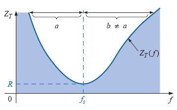
8 ZT VERSUS FREQUENCY Resistance, Inductive reactance and capacitive reactance versus frequency.

9
10 SELECTIVITY If we now plot the magnitude of the current I = E/ZT versus frequency for a fixed applied voltage E, we obtain the curve shown in Figure, which rises from zero to a maximum value of E/R (where ZT is a minimum) and then drops toward zero (as ZT increases) at a slower rate than it rose to its peak value. The curve is actually the inverse of the impedance-versus-frequency curve. I versus frequency for the series resonant circuit.
11 Those frequencies corresponding to of the maximum current are called the band frequencies, cutoff frequencies, or half-power frequencies. They are indicated by f1 and f2 The range of frequencies between the two is referred to as the bandwidth (BW) of the resonant circuit. Half-power frequencies are those frequencies at which the power delivered is 1/2 that delivered at the resonant frequency; that is,


12 Since the resonant circuit is adjusted to select a band of frequencies, the curve of Figure is called the selectivity curve. The term is derived from the fact that one must be selective in choosing the frequency to ensure that it is in the bandwidth. The smaller the bandwidth, the higher the selectivity Effect of R, L, and C on the selectivity curve for the series resonant circuit.
13 A small Qs, therefore, is associated with a resonant curve having a large bandwidth and a small selectivity, while a large Qs indicates the opposite. For circuits where Qs 10, a widely accepted approximation is that the resonant frequency bisects the bandwidth and that the resonant curve is symmetrical about the resonant frequency.
14 The ratio ( f2- f1)/fs is sometimes called the fractional bandwidth, providing an indication of the width of the bandwidth compared to the resonant frequency.
15 EXAMPLE 1 a. For the series resonant circuit of Figure, find I, VR, VL, and VC at resonance. b. What is the Qs of the circuit? c. If the resonant frequency is 5000 Hz, find the bandwidth. d. What is the power dissipated in the circuit at the half-power frequencies? Solutions:
16 EXAMPLE 2 The bandwidth of a series resonant circuit is 400 Hz. a. If the resonant frequency is 4000 Hz, what is the value of Qs? b. If R =10Ω, what is the value of XL at resonance? c. Find the inductance L and capacitance C of the circuit. Solutions:
17 EXAMPLE 3 A series R-L-C circuit has a series resonant frequency of 12,000 Hz. a. If R = 5, and if XL at resonance is 300, find the bandwidth. b. Find the cutoff frequencies. Solutions:
18 EXAMPLE 4 a. Determine the Qs and bandwidth for the response curve of Figure b. For C = nf, determine L and R for the series resonant circuit. c. Determine the applied voltage. Solutions: a. The resonant frequency is 2800 Hz from figure. At times the peak value, BW 200 Hz
19 EXAMPLE 5 A series R-L-C circuit is designed to resonant at s rad/s, have a bandwidth of 0.15 s, and draw 16 W from a 120-V source at resonance. a. Determine the value of R. b. Find the bandwidth in hertz. c. Find the nameplate values of L and C. d. Determine the Qs of the circuit. e. Determine the fractional bandwidth. Solutions:
20


21 2. PARALLEL RESONANT CIRCUIT Fig. 1Ideal parallel resonant network. Fig 2 Practical parallel L-C network


22 Fig. 3 Equivalent parallel network for a series R-L combination Redrawing the network of Fig. 2 with the equivalent of Fig. 3 and a practical current source having an internal resistance Rs will result in the network of Fig. 4. Fig. 4 Substituting the equivalent parallel network for the series R-L combination of Fig. 2.

23 If we define the parallel combination of Rs and Rp by the notation Fig.5 Substituting R = Rs//Rp for the network of Fig.4 Unity Power Factor, fp
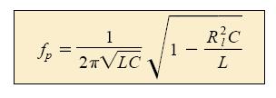
24 For unity power factor, the reactive component must be zero as defined by Multiplying the top and bottom of the factor within the square-root sign by C/L produces
25

26 Maximum Impedance, fm At f = fp the input impedance of a parallel resonant circuit will be near its maximum value but not quite its maximum value due to the frequency dependence of Rp. The frequency at which maximum impedance will occur is defined by fm and is slightly more than fp, as demonstrated in Fig.6. Once fm is determined, the network of Fig. 6 can be used to determine the magnitude and phase angle the total impedance at the resonance condition simply by substituting f = fm and performing the required calculations. That is, Fig. 6 ZT versus frequency for the parallel resonant circuit.
27 SELECTIVITY CURVE FOR PARALLEL RESONANT CIRCUITS Since the current I of the current source is constant for any value of ZT or frequency, the voltage across the parallel circuit will have the same shape as the total impedance ZT, as Fig. 7 Defining the shape of the Vp (f) curve. Since the voltage across parallel elements is the same, The resonant value of VC is therefore determined by the value of ZTm and the magnitude of the current source I.
28 The quality factor of the parallel resonant circuit continues to be determined by the ratio of the reactive power to the real power. That is, For the ideal current source (Rs= ) or when Rs is sufficiently large compared to Rp, we can make the following approximation:


29 Phase plot for the parallel resonant circuit.

30 EXAMPLE 6 Given the parallel network of Figure composed of ideal elements: a. Determine the resonant frequency fp. b. Find the total impedance at resonance. c. Calculate the quality factor, bandwidth, and cutoff frequencies f1 and f2 of the system. d. Find the voltage VC at resonance. e. Determine the currents IL and IC at resonance Solutions: a. The fact that Rl is zero ohms results in a very high Ql ( XL/Rl), permitting the use of the following equation for fp:
31 b. For the parallel reactive elements: but XL= XC at resonance
32 EXAMPLE 7 For the parallel resonant circuit of Figure with Rs= a. Determine fs, fm, and fp, and compare their levels. b. Calculate the maximum impedance and the magnitude of the voltage VC at fm. c. Determine the quality factor Qp. d. Calculate the bandwidth.
33 Solutions:
34
Resonance. A resonant circuit (series or parallel) must have an inductive and a capacitive element.
 must have an inductive and a capacitive element.") 1. Series Resonant: Resonance A resonant circuit (series or parallel) must have an inductive and a capacitive element. The total impedance of this network is: The circuit will reach its maximum Voltage
1. Series Resonant: Resonance A resonant circuit (series or parallel) must have an inductive and a capacitive element. The total impedance of this network is: The circuit will reach its maximum Voltage
Class: Second Subject: Electrical Circuits 2 Lecturer: Dr. Hamza Mohammed Ridha Al-Khafaji
 10.1 Introduction Class: Second Lecture Ten esonance This lecture will introduce the very important resonant (or tuned) circuit, which is fundamental to the operation of a wide variety of electrical and
UNIVERSITY OF BABYLON BASIC OF ELECTRICAL ENGINEERING LECTURE NOTES. Resonance
 Resonance The resonant(or tuned) circuit, in one of its many forms, allows us to select a desired radio or television signal from the vast number of signals that are around us at any time. Resonant electronic
Lab 1: Basic RL and RC DC Circuits
 Name- Surname: ID: Department: Lab 1: Basic RL and RC DC Circuits Objective In this exercise, the DC steady state response of simple RL and RC circuits is examined. The transient behavior of RC circuits
University of Jordan School of Engineering Electrical Engineering Department. EE 219 Electrical Circuits Lab
 University of Jordan School of Engineering Electrical Engineering Department EE 219 Electrical Circuits Lab EXPERIMENT 7 RESONANCE Prepared by: Dr. Mohammed Hawa EXPERIMENT 7 RESONANCE OBJECTIVE This experiment
Questions Bank of Electrical Circuits
 Questions Bank of Electrical Circuits 1. If a 100 resistor and a 60 XL are in series with a 115V applied voltage, what is the circuit impedance? 2. A 50 XC and a 60 resistance are in series across a 110V
BAKISS HIYANA BT ABU BAKAR JKE,POLISAS
 BAKISS HIYANA BT ABU BAKAR JKE,POLISAS 1 1. Explain AC circuit concept and their analysis using AC circuit law. 2. Apply the knowledge of AC circuit in solving problem related to AC electrical circuit.
Study of Inductive and Capacitive Reactance and RLC Resonance
 Objective Study of Inductive and Capacitive Reactance and RLC Resonance To understand how the reactance of inductors and capacitors change with frequency, and how the two can cancel each other to leave
Chapter 30 Inductance, Electromagnetic. Copyright 2009 Pearson Education, Inc.
 Chapter 30 Inductance, Electromagnetic Oscillations, and AC Circuits 30-7 AC Circuits with AC Source Resistors, capacitors, and inductors have different phase relationships between current and voltage
ELEN 140 ELECTRICAL CIRCUITS II Winter 2013
 ELEN 140 ELECTRICAL CIRCUITS II Winter 2013 Professor: Stephen O Loughlin Prerequisite: ELEN 130 Office: C234B Co-requisite: none Office Ph: (250) 762-5445 ext 4376 Lecture: 3.0 hrs/week Email: soloughlin@okanagan.bc.ca
Electricity & Optics
 Physics 24100 Electricity & Optics Lecture 19 Chapter 29 sec. 1,2,5 Fall 2017 Semester Professor Koltick Series and Parallel R and L Resistors and inductors in series: R series = R 1 + R 2 L series = L
Lecture 16 Date: Frequency Response (Contd.)
") Lecture 16 Date: 03.10.2017 Frequency Response (Contd.) Bode Plot (contd.) Bode Plot (contd.) Bode Plot (contd.) not every transfer function has all seven factors. To sketch the Bode plots for a generic
Lecture 16 Date: 03.10.2017 Frequency Response (Contd.) Bode Plot (contd.) Bode Plot (contd.) Bode Plot (contd.) not every transfer function has all seven factors. To sketch the Bode plots for a generic
CHAPTER 2. Basic Concepts, Three-Phase Review, and Per Unit
 CHAPTER 2 Basic Concepts, Three-Phase Review, and Per Unit 1 AC power versus DC power DC system: - Power delivered to the load does not fluctuate. - If the transmission line is long power is lost in the
ET1210: Module 5 Inductance and Resonance
 Part 1 Inductors Theory: When current flows through a coil of wire, a magnetic field is created around the wire. This electromagnetic field accompanies any moving electric charge and is proportional to
CHAPTER 14. Introduction to Frequency Selective Circuits
 CHAPTER 14 Introduction to Frequency Selective Circuits Frequency-selective circuits Varying source frequency on circuit voltages and currents. The result of this analysis is the frequency response of
Chapter 31 Alternating Current
 Chapter 31 Alternating Current In this chapter we will learn how resistors, inductors, and capacitors behave in circuits with sinusoidally vary voltages and currents. We will define the relationship between
CHAPTER 9. Sinusoidal Steady-State Analysis
 CHAPTER 9 Sinusoidal Steady-State Analysis 9.1 The Sinusoidal Source A sinusoidal voltage source (independent or dependent) produces a voltage that varies sinusoidally with time. A sinusoidal current source
Lab #5 ENG RC Circuits
 Name:. Lab #5 ENG 220-001 Date: Learning objectives of this experiment is that students will be able to: Measure the effects of frequency upon an RC circuit Calculate and understand circuit current, impedance,
Question Paper Profile
 I Scheme Question Paper Profile Program Name : Electrical Engineering Program Group Program Code : EE/EP/EU Semester : Third Course Title : Electrical Circuits Max. Marks : 70 Time: 3 Hrs. Instructions:
Sirindhorn International Institute of Technology Thammasat University
 Sirindhorn International Institute of Technology Thammasat University School of Information, Computer and Communication Technology COURSE : ECS 34 Basic Electrical Engineering Lab INSTRUCTOR : Dr. Prapun
AC Power Instructor Notes
 Chapter 7: AC Power Instructor Notes Chapter 7 surveys important aspects of electric power. Coverage of Chapter 7 can take place immediately following Chapter 4, or as part of a later course on energy
Physics Class 12 th NCERT Solutions
 Chapter.7 Alternating Current Class XII Subject Physics 7.1. A 100 Ω resistor is connected to a 220 V, 50 Hz ac supply. a) What is the rms value of current in the circuit? b) What is the net power consumed
Chapter 7. Copyright The McGraw-Hill Companies, Inc. Permission required for reproduction or display.
 Chapter 7 Copyright The McGraw-Hill Companies, Inc. Permission required for reproduction or display. Learning Objectives 1. Understand the meaning of instantaneous and average power, master AC power notation,
PHYSICS 221 LAB #6: CAPACITORS AND AC CIRCUITS
 Name: Partners: PHYSICS 221 LAB #6: CAPACITORS AND AC CIRCUITS The electricity produced for use in homes and industry is made by rotating coils of wire in a magnetic field, which results in alternating
Series and Parallel Resonant Circuits
 Series and Parallel Resonant Circuits Aim: To obtain the characteristics of series and parallel resonant circuits. Apparatus required: Decade resistance box, Decade inductance box, Decade capacitance box
LC Resonant Circuits Dr. Roger King June Introduction
 LC Resonant Circuits Dr. Roger King June 01 Introduction Second-order systems are important in a wide range of applications including transformerless impedance-matching networks, frequency-selective networks,
EE233 Autumn 2016 Electrical Engineering University of Washington. EE233 HW7 Solution. Nov. 16 th. Due Date: Nov. 23 rd
 EE233 HW7 Solution Nov. 16 th Due Date: Nov. 23 rd 1. Use a 500nF capacitor to design a low pass passive filter with a cutoff frequency of 50 krad/s. (a) Specify the cutoff frequency in hertz. fc c 50000
Exercise 1: Series RLC Circuits
 RLC Circuits AC 2 Fundamentals Exercise 1: Series RLC Circuits EXERCISE OBJECTIVE When you have completed this exercise, you will be able to analyze series RLC circuits by using calculations and measurements.
EECS40 RLC Lab guide
 EECS40 RLC Lab guide Introduction Second-Order Circuits Second order circuits have both inductor and capacitor components, which produce one or more resonant frequencies, ω0. In general, a differential
AC Circuits. "Look for knowledge not in books but in things themselves." W. Gilbert ( )
") AC Circuits "Look for knowledge not in books but in things themselves." W. Gilbert (1540-1603) OBJECTIVES To study some circuit elements and a simple AC circuit. THEORY All useful circuits use varying
AC Circuits "Look for knowledge not in books but in things themselves." W. Gilbert (1540-1603) OBJECTIVES To study some circuit elements and a simple AC circuit. THEORY All useful circuits use varying
Exercise 1: Series Resonant Circuits
 Series Resonance AC 2 Fundamentals Exercise 1: Series Resonant Circuits EXERCISE OBJECTIVE When you have completed this exercise, you will be able to compute the resonant frequency, total current, and
LRC Circuit PHYS 296 Your name Lab section
 LRC Circuit PHYS 296 Your name Lab section PRE-LAB QUIZZES 1. What will we investigate in this lab? 2. Figure 1 on the following page shows an LRC circuit with the resistor of 1 Ω, the capacitor of 33
GRADE 12 SEPTEMBER 2012 ELECTRICAL TECHNOLOGY
 Province of the EASTERN CAPE EDUCATION NATIONAL SENIOR CERTIFICATE GRADE 12 SEPTEMBER 2012 ELECTRICAL TECHNOLOGY MARKS: 200 TIME: 3 hours This question paper consists of 11 pages and a formula sheet. 2
Chapter 33. Alternating Current Circuits
 Chapter 33 Alternating Current Circuits Alternating Current Circuits Electrical appliances in the house use alternating current (AC) circuits. If an AC source applies an alternating voltage to a series
INTRODUCTION TO AC FILTERS AND RESONANCE
 AC Filters & Resonance 167 Name Date Partners INTRODUCTION TO AC FILTERS AND RESONANCE OBJECTIVES To understand the design of capacitive and inductive filters To understand resonance in circuits driven
Homework Assignment 05
 Homework Assignment 05 Question (2 points each unless otherwise indicated)(20 points). Estimate the parallel parasitic capacitance of a mh inductor with an SRF of 220 khz. Answer: (2π)(220 0 3 ) = ( 0
Assist Lecturer: Marwa Maki. Active Filters
 Active Filters In past lecture we noticed that the main disadvantage of Passive Filters is that the amplitude of the output signals is less than that of the input signals, i.e., the gain is never greater
Low Pass Filter Introduction
 Low Pass Filter Introduction Basically, an electrical filter is a circuit that can be designed to modify, reshape or reject all unwanted frequencies of an electrical signal and accept or pass only those
CHAPTER 6: ALTERNATING CURRENT
 CHAPTER 6: ALTERNATING CURRENT PSPM II 2005/2006 NO. 12(C) 12. (c) An ac generator with rms voltage 240 V is connected to a RC circuit. The rms current in the circuit is 1.5 A and leads the voltage by
Impedance, Resonance, and Filters. Al Penney VO1NO
 Impedance, Resonance, and Filters A Quick Review Before discussing Impedance, we must first understand capacitive and inductive reactance. Reactance Reactance is the opposition to the flow of Alternating
LCR Parallel Circuits
 Module 10 AC Theory Introduction to What you'll learn in Module 10. The LCR Parallel Circuit. Module 10.1 Ideal Parallel Circuits. Recognise ideal LCR parallel circuits and describe the effects of internal
Exercise 2: Parallel RLC Circuits
 RLC Circuits AC 2 Fundamentals Exercise 2: Parallel RLC Circuits EXERCSE OBJECTVE When you have completed this exercise, you will be able to analyze parallel RLC circuits by using calculations and measurements.
TUNED AMPLIFIERS 5.1 Introduction: Coil Losses:
 TUNED AMPLIFIERS 5.1 Introduction: To amplify the selective range of frequencies, the resistive load R C is replaced by a tuned circuit. The tuned circuit is capable of amplifying a signal over a narrow
Alternating Current Page 1 30
 Alternating Current 26201 11 Page 1 30 Calculate the peak and effective voltage of current values for AC Calculate the phase relationship between two AC waveforms Describe the voltage and current phase
Chapter 19. Basic Filters
 Chapter 19 Basic Filters Objectives Analyze the operation of RC and RL lowpass filters Analyze the operation of RC and RL highpass filters Analyze the operation of band-pass filters Analyze the operation
No Brain Too Small PHYSICS
 ELECTRICITY: AC QUESTIONS No Brain Too Small PHYSICS MEASURING IRON IN SAND (2016;3) Vivienne wants to measure the amount of iron in ironsand mixtures collected from different beaches. The diagram below
Downloaded from / 1
 PURWANCHAL UNIVERSITY II SEMESTER FINAL EXAMINATION-2008 LEVEL : B. E. (Computer/Electronics & Comm.) SUBJECT: BEG123EL, Electrical Engineering-I Full Marks: 80 TIME: 03:00 hrs Pass marks: 32 Candidates
EXPERIMENT 8: LRC CIRCUITS
 EXPERIMENT 8: LRC CIRCUITS Equipment List S 1 BK Precision 4011 or 4011A 5 MHz Function Generator OS BK 2120B Dual Channel Oscilloscope V 1 BK 388B Multimeter L 1 Leeds & Northrup #1532 100 mh Inductor
PHYSICS - CLUTCH CH 29: ALTERNATING CURRENT.
 !! www.clutchprep.com CONCEPT: ALTERNATING VOLTAGES AND CURRENTS BEFORE, we only considered DIRECT CURRENTS, currents that only move in - NOW we consider ALTERNATING CURRENTS, currents that move in Alternating
AC Circuit. What is alternating current? What is an AC circuit?
 Chapter 21 Alternating Current Circuits and Electromagnetic Waves 1. Alternating Current 2. Resistor in an AC circuit 3. Capacitor in an AC circuit 4. Inductor in an AC circuit 5. RLC series circuit 6.
Impedance, Resonance, and Filters. Al Penney VO1NO
 Impedance, Resonance, and Filters Al Penney VO1NO A Quick Review Before discussing Impedance, we must first understand capacitive and inductive reactance. Reactance Reactance is the opposition to the flow
Chapter 28 Alternating Current Circuits
 History teaches us that the searching spirit of man required thousands of years for the discovery of the fundamental principles of the sciences, on which the superstructure was then raised in a comparatively
Resonance Circuits and Applications
 International Journal of Inventive Engineering and Sciences (IJIES) ISSN: 2319 9598, Volume-3 Issue-5, April 2015 Resonance Circuits and Applications Manal Abdul Ameer Qabazard Abstract This paper presents
Advanced Measurements
 Albaha University Faculty of Engineering Mechanical Engineering Department Lecture 9: Wheatstone Bridge and Filters Ossama Abouelatta o_abouelatta@yahoo.com Mechanical Engineering Department Faculty of
AC CURRENTS, VOLTAGES, FILTERS, and RESONANCE
 July 22, 2008 AC Currents, Voltages, Filters, Resonance 1 Name Date Partners AC CURRENTS, VOLTAGES, FILTERS, and RESONANCE V(volts) t(s) OBJECTIVES To understand the meanings of amplitude, frequency, phase,
Chapter 25 Alternating Currents
 Chapter 25 Alternating Currents GOALS When you have mastered the contents of this chapter, you will be able to achieve the following goals: Definitions Define each of the following terms and use it in
Application Note Receivers MLX71120/21 With LNA1-SAW-LNA2 configuration
 Designing with MLX71120 and MLX71121 receivers using a SAW filter between LNA1 and LNA2 Scope Many receiver applications, especially those for automotive keyless entry systems require good sensitivity
LCR CIRCUITS Institute of Lifelong Learning, University of Delhi
 L UTS nstitute of Lifelong Learning, University of Delhi L UTS PHYSS (LAB MANUAL) nstitute of Lifelong Learning, University of Delhi PHYSS (LAB MANUAL) L UTS ntroduction ircuits containing an inductor
Chapter 2. The Fundamentals of Electronics: A Review
 Chapter 2 The Fundamentals of Electronics: A Review Topics Covered 2-1: Gain, Attenuation, and Decibels 2-2: Tuned Circuits 2-3: Filters 2-4: Fourier Theory 2-1: Gain, Attenuation, and Decibels Most circuits
A handy mnemonic (memory aid) for remembering what leads what is ELI the ICEman E leads I in an L; I leads E in a C.
 for remembering what leads what is ELI the ICEman E leads I in an L; I leads E in a C.") Amateur Extra Class Exam Guide Section E5A Page 1 of 5 E5A Resonance and Q: characteristics of resonant circuits: series and parallel resonance; Q; half-power bandwidth; phase relationships in reactive
Amateur Extra Class Exam Guide Section E5A Page 1 of 5 E5A Resonance and Q: characteristics of resonant circuits: series and parallel resonance; Q; half-power bandwidth; phase relationships in reactive
Electrical Theory. Power Principles and Phase Angle. PJM State & Member Training Dept. PJM /22/2018
 Electrical Theory Power Principles and Phase Angle PJM State & Member Training Dept. PJM 2018 Objectives At the end of this presentation the learner will be able to: Identify the characteristics of Sine
UNIT 1 CIRCUIT ANALYSIS 1 What is a graph of a network? When all the elements in a network is replaced by lines with circles or dots at both ends.
 UNIT 1 CIRCUIT ANALYSIS 1 What is a graph of a network? When all the elements in a network is replaced by lines with circles or dots at both ends. 2 What is tree of a network? It is an interconnected open
UNIVERSITY OF BOLTON SCHOOL OF SPORT AND BIOMEDICAL SCIENCE. BEng (HONS)/MEng BIOMEDICAL ENGINEERING. BEng (HONS) MEDICAL ENGINEERING
/MEng BIOMEDICAL ENGINEERING. BEng (HONS) MEDICAL ENGINEERING") LH29 SCHOOL OF SPORT AND BIOMEDICAL SCIENCE BEng (HONS)/MEng BIOMEDICAL ENGINEERING BEng (HONS) MEDICAL ENGINEERING SEMESTER 2 EXAMINATIONS 2015/2016 MODULE NO: BME4004 Date: Wednesday 18 May 2016 Time:
LH29 SCHOOL OF SPORT AND BIOMEDICAL SCIENCE BEng (HONS)/MEng BIOMEDICAL ENGINEERING BEng (HONS) MEDICAL ENGINEERING SEMESTER 2 EXAMINATIONS 2015/2016 MODULE NO: BME4004 Date: Wednesday 18 May 2016 Time:
Chapter 33. Alternating Current Circuits
 Chapter 33 Alternating Current Circuits C HAP T E O UTLI N E 33 1 AC Sources 33 2 esistors in an AC Circuit 33 3 Inductors in an AC Circuit 33 4 Capacitors in an AC Circuit 33 5 The L Series Circuit 33
Lab #5 Steady State Power Analysis
 Lab #5 Steady State Power Analysis Steady state power analysis refers to the power analysis of circuits that have one or more sinusoid stimuli. This lab covers the concepts of RMS voltage, maximum power
Chapter 11. Alternating Current
 Unit-2 ECE131 BEEE Chapter 11 Alternating Current Objectives After completing this chapter, you will be able to: Describe how an AC voltage is produced with an AC generator (alternator) Define alternation,
DOING PHYSICS WITH MATLAB RESONANCE CIRCUITS SERIES RLC CIRCUITS
 DOING PHYSICS WITH MATLAB RESONANCE CIRCUITS SERIES RLC CIRCUITS Matlab download directory Matlab scripts CRLCs1.m CRLCs2.m Graphical analysis of a series RLC resonance circuit Fitting a theoretical curve
ANADOLU UNIVERSITY FACULTY OF ENGINEERING AND ARCHITECTURE DEPARTMENT OF ELECTRICAL AND ELECTRONICS ENGINEERING
 ANADOLU UNIVERSITY FACULTY OF ENGINEERING AND ARCHITECTURE DEPARTMENT OF ELECTRICAL AND ELECTRONICS ENGINEERING EEM 206 ELECTRICAL CIRCUITS LABORATORY EXPERIMENT#3 RESONANT CIRCUITS 1 RESONANT CIRCUITS
A.C. FILTER NETWORKS. Learning Objectives
 C H A P T E 17 Learning Objectives Introduction Applications Different Types of Filters Octaves and Decades of Frequency Decibel System alue of 1 db Low-Pass C Filter Other Types of Low-Pass Filters Low-Pass
Laboratory Project 4: Frequency Response and Filters
 2240 Laboratory Project 4: Frequency Response and Filters K. Durney and N. E. Cotter Electrical and Computer Engineering Department University of Utah Salt Lake City, UT 84112 Abstract-You will build a
KINGS COLLEGE OF ENGINEERING DEPARTMENT OF ELECTRICAL AND ELECTRONICS ENGINEERING QUESTION BANK UNIT I BASIC CIRCUITS ANALYSIS PART A (2-MARKS)
") KINGS COLLEGE OF ENGINEERING DEPARTMENT OF ELECTRICAL AND ELECTRONICS ENGINEERING QUESTION BANK YEAR / SEM : I / II SUBJECT CODE & NAME : EE 1151 CIRCUIT THEORY UNIT I BASIC CIRCUITS ANALYSIS PART A (2-MARKS)
KINGS COLLEGE OF ENGINEERING DEPARTMENT OF ELECTRICAL AND ELECTRONICS ENGINEERING QUESTION BANK YEAR / SEM : I / II SUBJECT CODE & NAME : EE 1151 CIRCUIT THEORY UNIT I BASIC CIRCUITS ANALYSIS PART A (2-MARKS)
Characteristics of Crystal. Piezoelectric effect of Quartz Crystal
 Characteristics of Crystal Piezoelectric effect of Quartz Crystal The quartz crystal has a character when the pressure is applied to the direction of the crystal axis, the electric change generates on
ELC224 Final Review (12/10/2009) Name:
 Name:") ELC224 Final Review (12/10/2009) Name: Select the correct answer to the problems 1 through 20. 1. A common-emitter amplifier that uses direct coupling is an example of a dc amplifier. 2. The frequency
ELC224 Final Review (12/10/2009) Name: Select the correct answer to the problems 1 through 20. 1. A common-emitter amplifier that uses direct coupling is an example of a dc amplifier. 2. The frequency
Exercise 2: Q and Bandwidth of a Series RLC Circuit
 Series Resonance AC 2 Fundamentals Exercise 2: Q and Bandwidth of a Series RLC Circuit EXERCISE OBJECTIVE When you have completed this exercise, you will be able to calculate the bandwidth and Q of a series
Chapter 6: Alternating Current. An alternating current is an current that reverses its direction at regular intervals.
 Chapter 6: Alternating Current An alternating current is an current that reverses its direction at regular intervals. Overview Alternating Current Phasor Diagram Sinusoidal Waveform A.C. Through a Resistor
AC reactive circuit calculations
 AC reactive circuit calculations This worksheet and all related files are licensed under the Creative Commons Attribution License, version 1.0. To view a copy of this license, visit http://creativecommons.org/licenses/by/1.0/,
Chapter 31. Alternating Current. PowerPoint Lectures for University Physics, 14th Edition Hugh D. Young and Roger A. Freedman Lectures by Jason Harlow
 Chapter 31 Alternating Current PowerPoint Lectures for University Physics, 14th Edition Hugh D. Young and Roger A. Freedman Lectures by Jason Harlow Learning Goals for Chapter 31 Looking forward at How
ALTERNATING CURRENT CIRCUITS
 CHAPTE 23 ALTENATNG CUENT CCUTS CONCEPTUAL QUESTONS 1. EASONNG AND SOLUTON A light bulb and a parallel plate capacitor (including a dielectric material between the plates) are connected in series to the
VALLIAMMAI ENGINEERING COLLEGE
 P a g e 2 Question Bank Programme Subject Semester / Branch : BE : EE6201-CIRCUIT THEORY : II/EEE,ECE &EIE UNIT-I PART-A 1. Define Ohm s Law (B.L.T- 1) 2. List and define Kirchoff s Laws for electric circuits.
Experiment 9 AC Circuits
 Experiment 9 AC Circuits "Look for knowledge not in books but in things themselves." W. Gilbert (1540-1603) OBJECTIVES To study some circuit elements and a simple AC circuit. THEORY All useful circuits
The Amazing MFJ 269 Author Jack Tiley AD7FO
 The Amazing MFJ 269 Author Jack Tiley AD7FO ARRL Certified Emcomm and license class Instructor, Volunteer Examiner, EWA Technical Coordinator and President of the Inland Empire VHF Club What Can be Measured?
AC Circuit Analysis. The Sine Wave CHAPTER 3. This chapter discusses basic concepts in the analysis of AC circuits.
 CHAPTER 3 AC Circuit Analysis This chapter discusses basic concepts in the analysis of AC circuits. The Sine Wave AC circuit analysis usually begins with the mathematical expression for a sine wave: v(t)
not to be republished NCERT ALTERNATING CURRENT Chapter Seven MCQ 1
 hapter Seven ALTERNATING URRENT MQ 1 7.1 If the rms current in a 50 Hz ac circuit is 5 A, the value of the current 1/300 seconds after its value becomes zero is (a) 5 2 A (b) 5 3/2 A (c) 5/6 A (d) 5/ 2
Transmission Line Models Part 1
 Transmission Line Models Part 1 Unlike the electric machines studied so far, transmission lines are characterized by their distributed parameters: distributed resistance, inductance, and capacitance. The
Understanding VCO Concepts
 Understanding VCO Concepts OSCILLATOR FUNDAMENTALS An oscillator circuit can be modeled as shown in Figure 1 as the combination of an amplifier with gain A (jω) and a feedback network β (jω), having frequency-dependent
PHYSICS WORKSHEET CLASS : XII. Topic: Alternating current
 PHYSICS WORKSHEET CLASS : XII Topic: Alternating current 1. What is mean by root mean square value of alternating current? 2. Distinguish between the terms effective value and peak value of an alternating
The steeper the phase shift as a function of frequency φ(ω) the more stable the frequency of oscillation
 the more stable the frequency of oscillation") It should be noted that the frequency of oscillation ω o is determined by the phase characteristics of the feedback loop. the loop oscillates at the frequency for which the phase is zero The steeper the
It should be noted that the frequency of oscillation ω o is determined by the phase characteristics of the feedback loop. the loop oscillates at the frequency for which the phase is zero The steeper the
PHYS 3322 Modern Laboratory Methods I AC R, RC, and RL Circuits
 Purpose PHYS 3322 Modern Laboratory Methods I AC, C, and L Circuits For a given frequency, doubling of the applied voltage to resistors, capacitors, and inductors doubles the current. Hence, each of these
Measurement of the equivalent circuit of quartz crystals
 Measurement of the equivalent circuit of quartz crystals This application note shows how to measure the equivalent circuit of a quartz crystal with Bode 100. A.) Basics: An equivalent describtion of a
AP Physics C. Alternating Current. Chapter Problems. Sources of Alternating EMF
 AP Physics C Alternating Current Chapter Problems Sources of Alternating EMF 1. A 10 cm diameter loop of wire is oriented perpendicular to a 2.5 T magnetic field. What is the magnetic flux through the
EXPERIMENT FREQUENCY RESPONSE OF AC CIRCUITS. Structure. 8.1 Introduction Objectives
 EXPERIMENT 8 FREQUENCY RESPONSE OF AC CIRCUITS Frequency Response of AC Circuits Structure 81 Introduction Objectives 8 Characteristics of a Series-LCR Circuit 83 Frequency Responses of a Resistor, an
Revised April Unit/Standard Number. Proficiency Level Achieved: (X) Indicates Competency Achieved to Industry Proficiency Level
 Indicates Competency Achieved to Industry Proficiency Level") Unit/Standard Number Electrical, Electronic and Communications Engineering Technology/Technician CIP 15.0303 Task Grid Secondary Competency Task List 100 SAFETY 101 Demonstrate an understanding of state,
Unit/Standard Number Electrical, Electronic and Communications Engineering Technology/Technician CIP 15.0303 Task Grid Secondary Competency Task List 100 SAFETY 101 Demonstrate an understanding of state,
Lab E5: Filters and Complex Impedance
 E5.1 Lab E5: Filters and Complex Impedance Note: It is strongly recommended that you complete lab E4: Capacitors and the RC Circuit before performing this experiment. Introduction Ohm s law, a well known
EE 340L EXPERIMENT # 5.1 SYNCHRONOUS GENERATOR (STAND-ALONE OPERATION)
") EE 340L EXPERIMENT # 5.1 SYNCHRONOUS GENERATOR (STAND-ALONE OPERATION) A. Equivalent Circuit Parameters A.1. Open-Circuit Test (a) Mechanically couple the generator with a shunt-excited DC motor as shown
EE 340L EXPERIMENT # 5.1 SYNCHRONOUS GENERATOR (STAND-ALONE OPERATION) A. Equivalent Circuit Parameters A.1. Open-Circuit Test (a) Mechanically couple the generator with a shunt-excited DC motor as shown
CHAPTER 7. Response of First-Order RL and RC Circuits
 CHAPTER 7 Response of First-Order RL and RC Circuits RL and RC Circuits RL (resistor inductor) and RC (resistor-capacitor) circuits. Figure 7.1 The two forms of the circuits for natural response. (a) RL
Analytical Review of the Roomcap Antenna Felix Meyer, July 10th 2014
 Analytical Review of the Roomcap Antenna copyright @ Felix Meyer, July 10th 2014 The RoomCap Antenna (RCA) is a new short wave antenna construction that reaches the efficiency of large antennas. The RCA
K6RIA, Extra Licensing Class. Circuits & Resonance for All!
 K6RIA, Extra Licensing Class Circuits & Resonance for All! Amateur Radio Extra Class Element 4 Course Presentation ELEMENT 4 Groupings Rules & Regs Skywaves & Contesting Outer Space Comms Visuals & Video
Worksheet for Exploration 31.1: Amplitude, Frequency and Phase Shift
 Worksheet for Exploration 31.1: Amplitude, Frequency and Phase Shift We characterize the voltage (or current) in AC circuits in terms of the amplitude, frequency (period) and phase. The sinusoidal voltage
SHRI RAMSWAROOP MEMORIAL COLLEGE OF ENGG. & MANAGEMENT B.Tech. [SEM I (EE, EN, EC, CE)] QUIZ TEST-3 (Session: ) Time: 1 Hour ELECTRICAL ENGINEE
![SHRI RAMSWAROOP MEMORIAL COLLEGE OF ENGG. & MANAGEMENT B.Tech. [SEM I (EE, EN, EC, CE)] QUIZ TEST-3 (Session: ) Time: 1 Hour ELECTRICAL ENGINEE](/thumbs/94/118213481.jpg "SHRI RAMSWAROOP MEMORIAL COLLEGE OF ENGG. & MANAGEMENT B.Tech. [SEM I (EE, EN, EC, CE)] QUIZ TEST-3 (Session: ) Time: 1 Hour ELECTRICAL ENGINEE") SHRI RAMSWAROOP MEMORIAL COLLEGE OF ENGG. & MANAGEMENT B.Tech. [SEM I (EE, EN, EC, CE)] QUIZ TEST-3 (Session: 2014-15) Time: 1 Hour ELECTRICAL ENGINEERING Max. Marks: 30 (NEE-101) Roll No. Academic/26
SHRI RAMSWAROOP MEMORIAL COLLEGE OF ENGG. & MANAGEMENT B.Tech. [SEM I (EE, EN, EC, CE)] QUIZ TEST-3 (Session: 2014-15) Time: 1 Hour ELECTRICAL ENGINEERING Max. Marks: 30 (NEE-101) Roll No. Academic/26
DOING PHYSICS WITH MATLAB RESONANCE CIRCUITS RLC PARALLEL VOLTAGE DIVIDER
 DOING PHYSICS WITH MATLAB RESONANCE CIRCUITS RLC PARALLEL VOLTAGE DIVIDER Matlab download directory Matlab scripts CRLCp1.m CRLCp2.m When you change channels on your television set, an RLC circuit is used