DRAFT Expected performance of type-bp SAS in bkagra
|
|
|
- Gwendolyn Chandler
- 5 years ago
- Views:
Transcription
1 DRAFT Expected performance of type-bp SAS in bkagra December 27, 216 Yoshinori Fujii Table of Contents 1 Expected performance of type-bp SAS in bkagra Overview Mechanics Suspension system overview Security frame Sensors and actuators BF-LVDT Wide cavity OSEM Optical length sensor Expected performance Suspension mechanical response Controls in the calm-down phase Controls in the lock-acquisition phase Controls in observation phase Conclusion A Eigenmodes of type-bp SAS 21 B Active control system for type-bp SAS 24 B.1 Controls in calm-down phase B.2 Controls in lock acquisition and observation phase

2 1 Expected performance of type-bp SAS in bkagra As described in the previous section, the suspension system for the PR mirrors are upgraded toward bkagra from that was used in the ikagra period. This new system is called type-bp SAS, and three of them are to be installed at the site. This chapter describes the type-bp SAS system, its controllability, and the expected performance. 1.1 Overview The mechanical overview of the type-bpp SAS and the type-bp SAS are shown in figure 1.1. The type-bp SAS has two GAS filters to reduce coupling level from vertical to longitudinal vibration at higher frequency than 1 Hz. One recoil mass is also added at BF level with some sensor and actuator units called BF-LVDTs. It is suspended from beneath of the SF. This BF recoil mass (BR) system is aimed at damping main pendulum resonant modes by monitoring relative motion between the BF and the BR. Figure 1.1: Mechanical overview of the type-bpp SAS and the type-bp SAS. In addition, OSEM units are modified for risk reduction. For the IM-OSEM units, interval between LED and photo diode in IM-OSEMs are widened. While for the TM-OSEM units, the implemented sensors are removed from the type-bp SAS and their long flags are replaced into shorter ones. Thence the type-bp SAS has only optical length sensor and optical lever as the TM sensing system. Actuation system at TM level by TM-OSEMs remains. This chapter focus on detailed mechanics of the type-bp SAS and its active control system in each phase. Chapter 1.2 describes the detailed mechanical design of the type-bp SAS. The newly added sensor and actuator units are explained in chapter 1.3. Chapter 1.4 presents the expected vibration isolation performance of the type-bp SAS with active control system, and the control noise couping into the TM. 2
3 1.2 Mechanics This section explains the mechanics of the suspension system and the related structures. Most of the environment is same as that of the type-bpp SAS. Thence, this section especially focuses on the newly modified points. The suspension system is inside the vacuum chamber, and is surrounded by the extended security frame. The base of the suspension system is located on the inner frame inside the vacuum chamber. The inner frame stands on the ground Suspension system overview The detailed type-bp suspension system is shown in figure 1.2. The suspension system of the payload is same as that of type-bpp SAS. The payload includes the test mass (TM), the recoil mass (RM), the intermediate mass (IM), and the intermediate recoil mass (IR). The BF and the payload are suspended from above system by single wire. The BF recoil mass (BR) is suspended from base of the standard GAS filter(sf) by three maraging rods. The suspension wire connecting the components above the IM are made of maraging steel. In the type-bp SAS, the SF is supported by the traverser which conducts initial position alignment. the traverser stands on the top surface of the inner frame. Figure 1.2: Ovweview of the type-bp SAS Security frame 3
4 1.3 Sensors and actuators The newly added sensors and actuators are explained in this section BF-LVDT Wide cavity OSEM Optical length sensor 4
5 1.4 Expected performance The simulated performance of the newly designed type-bp SAS is described in this section. This section includes the expected frequency responses of the suspension system, and its vibration isolation performances when the active controls are implemented. The modeled high noise seismic vibration at CLIO site is assumed in this simulation. According to the measured seismic vibration at KAGRA site, it seems to have shallow peak at around 2 Hz, while the vibration at the CLIO site does not have the structure. However, there is still no statistical measurement of the seismic vibration at KAGRA site and also the peak does not contribute a lot for current designing active control system. Thence the model obtained from measurement of CLIO site is used in this simulation, instead of the vibration of KAGRA site. In addition, optimally suspended system is also assumed. There is no horizontal discrepancy between the suspension point and the center of mass for each suspended mass. The active control system is constructed so that the controls meets the requirements explained in chapter??, by considering the expected transfer functions of the suspension system described in chapter The designed servo filters and the expected vibration isolation performances for the each control phase are described in chapter to In following figures, the variable names of L, T, V, R, P, Y are used for expressing the DoFs of the vibration in this section. They are the first letter of the direction of the vibration (longitudinal, transversal, vertical, roll, pitch, yaw). The following two letters describes the name of the rigid bodies in the suspension system Suspension mechanical response The mechanical responses of the type-bp SAS is explained in this section explains. Figure 1.3 to figure 1.7 show the expected diagonal transfer functions from the implemented actuators to the sensors. According to the previous investigation, explained in chapter?? and [], these predicted transfer functions are expected to fit well with the measurement below around 3 Hz for the measurements with OSEMs, and below around 5 Hz for the measurements with LVDTs. Except for the points, measurements are expected to follow these predicted transfer functions in this section. The transfer functions in this section are fed back to the servo filter designs. The resonant frequencies of the type-bp SAS are summarized in table 1.1, and their eigenmode shapes are shown in appendix A. Diagonal transfer functions 1 2 VF1 1 2 VF Figure 1.3: Diagonal transfer function measured by GAS-LVDTs. 5
6 1 2 L 1 2 T 1 2 V R 1 2 P 1 2 Y Figure 1.4: Diagonal transfer functions measured by BF-LVDTs 1 2 L 1 2 T 1 2 V R 1 2 P 1 2 Y Figure 1.5: Diagonal transfer functions measured by IM-OSEMs 6
7 1 2 L 1 2 P 1 2 Y Figure 1.6: Diagonal transfer functions from oplevs to TM-OSEMs. 1 2 L 1 2 P 1 2 Y Figure 1.7: Diagonal transfer functions from oplevs to IM-OSEMs. 7
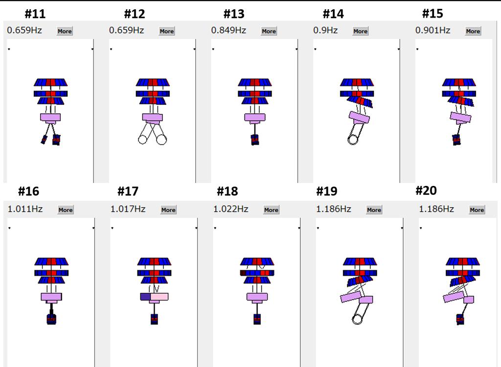
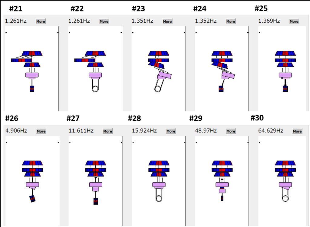
8 Eigenmodes from 3D rigid body model #Mode No. Frequwncy [Hz] Mode shape Note #1.1 YBF, YIR, YRM, YTM wire torsion #2.161 YIM, YRM, YTM wire torsion #3.325 VBF, VIR, VIM, VRM, VTM GAS filter #4.376 RIM, RRM, RTM IM roll #5.414 PIM, PRM, PTM IM pitch # RIM, TRM, -RRM, TTM, -RTM main pendulum #7.463 PIM, PRM, PTM main pendulum #8.612 RBF, TIR, RIR BF roll # PBF, LIR, PIR, PTM BF pitch #.618 VBF, VIR, -VIM, -VRM, -VTM GAS filter # PIM, -LRM, -PRM, LTM, -PTM TM-RM pendulum # RIM, TRM, -RRM, -TTM, -RTM TM-RM pendulum # PTM TM pitch #14.9 TBF, -RBF, -RRM, TIM, -TRM, -TTM main pendulum #15.1 -PBF, -PIR, PIM, PRM, -PTM main pendulum # YIM, -YRM, YTM TM yaw # YIR IR yaw # YBR BR yaw # RBF, -TIR, RIR, TIM main pendulum # PBF, LIR, PIR, -LIM main pendulum # LBR BR pendulum # TBR BR pendulum # RBF, TIR, -RIR, TIM IM pendulum # PBF, LIR, PIR, LIM IM pendulum # YIM, -YTM TM yaw # PIM, PRM RM pitch # VIM, -VRM, VTM TM vertical # RTM TM roll # YIM, YRM VRM # RIM, RRM RIM # PBR BR pitch # RBR BR roll # RIR IR roll # PIR IR pitch # VBR BR vertical # VIR IR vertical Table 1.1: Simulated eigenmode list of Type-B SASp for bkagra 8

9 1.4.2 Controls in the calm-down phase This section describes the active damping servos in the calm-down phase. The designing filters, its damping performances, and the sensor noise coupling to the interferometer signals are included. The servo filters are designed from the transfer functions from the implemented actuators and the sensors which are shown above. Servo filter design The schematic control diagram in the calm-down phase is shown in figure 1.8. The damping controls are set at the BF and IM levels by using the BF-LVDT units, and IM-OSEM units. Resonances of the vertical GAS filter vibration are damped by the GAS-LVDT and coil-magnet actuator unit, which is implemented into the SF. DC servos are also included in the GAS filter control loops to suppress the thermal drift of the GAS filters. At the TM level, damping loops by the optical lever and optical length sensor are implemented to suppress the relative motion between RM and TM, even though they have narrow linear range. This is because the sensors to measure the TM motion in the type-bp SAS are only them. In this section, the performance in 2 cases are investigated. First option is the case when the optical lever and the optical length sensor are available. The other option is the case if they are not available. Figure 1.9 to 1.11 show the Bode-plots of the designed servo filters in the calm-down phase. The displacement signals obtained by OSEM sensors and LVDTs are converted into the velocities with differentiation filters to get the viscous damping forces. Then, the converted signals are sent to the actuators with appropriate gains. The feedback filters have gains which is proportional to frequency f, around the mechanical resonant frequencies to be suppressed. The SF control gain has larger gain at the low frequencies to compensate the thermal drift of the GAS filters. The gains at high frequencies are cut off by low pass Butterworth filters with certain frequencies. In this calm-down phase, the cut-off frequencies are set at the lowest ones where all the mechanical resonances are suppressed within the requirement. Figure 1.8: Control loops in the calm down phase. 9
10 LBF TBF VBF Frequency (Hz) RBF PBF YBF Frequency (Hz) Figure 1.9: Servo filters for BF-level controls in the calm-down phase LIM TIM VIM Frequency (Hz) RIM PIM YIM Frequency (Hz) Figure 1.1: Servo filters for IM-level controls in the calm-down phase VF1 VF Frequency (Hz) LTM PTM YTM Frequency (Hz) Figure 1.11: Servo filters for GAS controls (Lef t), for TM-level controls (Right) in the calm-down phase. 1
11 Expected damping performance This section describes the performance of the damping control in terms of 1/e decay time of each mechanical resonance. 1/e decay time is a measure of the damping performance. The active control in this phase is required to damp the mechanical resonances with long decay time, especially at.1 Hz 1 Hz. The requirement for the decay time is to suppress the 1/e decay time to lower than 1 minute. Figure 1.12 shows the expected 1/e decay time for each resonant frequency of the type-bp SAS, with and without controls. The Lef t plot is the performance when the control loops with optical lever and optical length sensor at the TM level are opened, while the Right plot describes that when the control with these optical sensors are turned on. The former considers the optical sensors at the TM level are not available, while the latter supposes they are available. According to the plots in the former case, there are 3 resonant modes whose decay time exceed the requirement with active control, and according to the latter case, there is one such mode. Figure 1.13 shows those resonant mode shapes. All of these resonances are related with relative vibration between the TM and the RM in longitudinal, transversal and yaw DoFs, and thus to damp the resonances, sensing the TM motion is needed. If the optical sensors are available in the calm-down phase, the TM active control damps mode #11 and mode #16 (longitudinal and yaw DoF), which disturb the lock acquisition. On the other hand, the other mode #12 is not damped even if the TM controls are switched on, since there is no sensors and actuators for the TM motion in transversal DoF. However, the vibration which is related with the transversal DoF of the TM is not disturb the interferometer operation, unless its amplitude becomes larger than 1 mm. Thus there is no problem for this mode even if its decay time is larger than the requirement. 1/e decay time [sec] Control OFF Control ON Requirement (1 min.) Q = 1 Q = 1 1/e decay time [sec] Control OFF Control ON Requirement (1 min.) Q = 1 Q = Figure 1.12: Expected 1/e decay time for each mechanical resonances in the type-bp SAS with and without active control. Lef t shows the performance when the active control with optical sensors are not available, while Right describes that when the controls with the optical sensors are included. In conclusion, if the optical sensors at TM level is available in the calm-down phase, the active controls damps all the mechanical resonances which disturb the interferometer operation, within 1 minute which is requirement for this controls. On the other hand, if the optical lever is not available in this phase, one has to wait 3 1 minutes until the suspension system recovers its steady state. Note that the angular fluctuation of the mirror is required to be suppressed lower than about 5 µrad to keep the optical lever within its linear regime. Such fluctuation can be excited by earthquakes and failure of lock acquisitions. Thence the details about the excited amplitude by external disturbances and frequency of such events is to be investigated. 11
12 Figure 1.13: Mode shapes of the mechanical resonances whose 1/e decay time exceeds the requirement of 1 minute when the active control at TM level are not available (Left), while when the control with the optical sensors are working (Right). The 1/e decay time under this controls is expected around 2 sec for the mode #11, 25 sec for the mode #12, and 61 sec for the mode #16. Sensor noise couplings in the calm-down phase Figure 1.14 shows the expected noise couplings from each position sensor used in this control to longitudinal displacement of th TM. The considered noise sources are GAS-LVDTs, BF-LVDTs, and the optical sensors at TM level. In this simulation, it is assumed that there is no difference between the suspension position and the center of mass and thus no couplings from other DoF vibration due to mechanical asymmetry, as described above. The BF-LVDT, OSEM sensor, optical lever have 1 8 m/ Hz, 1 9 m/ Hz, and 1 7 rad/ Hz for their noise level in the band of target gravitational waves, respectively. The displacement noise of the TM caused by the IM-OSEMs and optical sensors are much larger than the required level as shown in the plot. Thence the control with the OSEMs and the optical sensors should be excluded or modified in the observation phase. The control noise from BF-LVDT also violates the requirement at 11 Hz. Since the peak at 11 Hz is comes from a resonant vibration of the TM in vertical direction, the servos by BF-LVDTs and OSEMs are to be opened in vertical DoF, in the observation phase. Table 1.2 shows the expected residual RMS values after the suspension system gets steady state. According to this table, all the simulated results meet the requirements for the calm down-phase controls. These predicted RMS values depend on mechanical Q factors of the resonant peaks, which have large uncertainty in this simulation. However, the actual mechanical Q factors of the KAGRA-SAS are either comparable with or lower than these predictions, comparing to the previous measurements. Thence the residual values of the actual suspension system is expected to be lower than the RMS. About yaw motion, this simulation does not include the prediction of its RMS, since predicting the precise yaw motion needs to consider asymmetry of the mechanical suspension system. There is also no detailed information about the asymmetry of the KAGRA-SAS. According to previous measurement which was done at TAMA site, where the magnitude of the seismic noise is much larger than that of the KAGRA site, its measured residual RMS of yaw motion was 4 µrad. Following these experiments, the amplitude of the residual yaw motion is expected to be lower than 4 µrad unless the suspension system has much asymmetries. displacement velocity Item longitudinal [µm] vertical [µm] pitch [µrad] longitudinal [µm/s] Residual RMS Table 1.2: Expected RMS values in the calm-down phase. The longitudinal, vertical, pitch displacement, and longitudinal velocity of the mirror are described in each column. 12
13 [m/ Hz] or RMS [m] IM OSEM noise GAS LVDT noise BF LVDT noise TM Oplev noise With control total No control With control total (RMS) No control (RMS) requirement Figure 1.14: Expected sensor noise couplings to longitudinal displacement of the TM in the active controls in the calm-down phase. Tn the plot, optical sensors are included into the control. This plot includes the noise coupling from IM-OSEMs (magenta), from GAS-LVDTs at SF and BF (green), from BF-LVDTs (cyan), optical sensors at TM level (yellow). The total control noise (red), passive performance (blue) are also plotted. The dashed lines describe the RMS of total control noise and passive performance, down to 1 2 Hz. 13

14 1.4.3 Controls in the lock-acquisition phase The aim of the control in the lock-acquisition phase is to suppress the RMS longitudinal velocity and RMS angular motion of the TM for the lock acquisition of the interferometer. Figure 1.15 shows the schematic diagram of this control phase. This active control is switched on, after the suspension system gets steady state. Figure 1.15: Control loops in the lock-acquisition phase. In this phase, control loops for the payload are changed. Since important role of this phase is aligning the TM for the interferometer lock, both of DC and damping servos are implemented in the mirror pitch and yaw motion. In this alignment control for the mirror angular motion is achieved by the alignment controls with the optical lever. The signals of mirror pitch and yaw vibration are measured by the optical lever, and are fed back to the actuators implemented at IM level. The damping filters for pitch and yaw vibration by IM-OSEMs are turned off when the controls with optical lever are switched on. This is aiming at avoiding competition between the optical lever control and OSEM one. Figure 1.16 to 1.18 show the Bode-plots of the designed servo filters in the lock-acquisition phase. The cut-off frequencies for the damping filters by BF-LVDTs and IM-OSEMs are set at ones where the resonances, which contribute to the RMS displacement of the mirror vibration, are efficiently damped. Figure 1.18 Right shows the servo filters for aligning the TM of suspended by the type-bp SAS. The shapes of the servos are aimed at compensating the phase delay of the mechanical system. In these filters, DC servos are implemented at low frequencies for the mirror alignment. At the region between around.1 Hz to the unity gain frequencies ( 2 Hz), the servo gains are raised by proportional to f 3 to compensate the phase delay due to the mechanical response. This is because the amplitude of the mechanical response gets smaller by proportional to f 4 and its phase delays 36 deg at high frequencies. The notch filter at 4.9 Hz in the pitch servo is included to avoid the instability of due to the mechanical response related with the pitch vibration of the recoil mass. The expected RMS of longitudinal displacement, velocity and pitch angular displacement in this controls are described in table 1.3. It is confirmed that the active controls for this phase are met with the requirements. The RMS of TM yaw motion is not calculated, however, according to the previous measurement, it is expected to meet the requirement. 14
15 Servo filter design LBF TBF VBF 1 2 RBF PBF YBF Frequency (Hz) Frequency (Hz) Figure 1.16: Servo filters for BF level controls in lock acquisition phase. 1 5 LIM TIM VIM RIM Frequency (Hz) Frequency (Hz) Figure 1.17: Servo filters IM level controls in lock acquisition phase VF1 VF Frequency (Hz) Frequency (Hz) P Y Figure 1.18: Servo filters for GAS controls (Lef t), for TM-level controls (Right) in lock acquisition phase. 15
16 Item displacement [µm] velocity [µm/s] pitch [µrad] Without controls With controls Table 1.3: Expected RMS of residual vibration in the calm down phase. The longitudinal displacement, longitudinal velocity, and pitch vibration of the mirror are described Controls in observation phase The most important role of the control in the observation phase is to suppress the displacement noise lower than the requirement at 1 Hz, keeping the requirements on the RMS. The servo filters shown in this section are also used in the observation phase. After the lock-acquisition phase, only the optical lever is to be changed into the wave front sensor (WFS) to reduce the noise level at the target gravitational wave band. Since the BF-LVDTs and IM-OSEMs have large sensor noises, the control by these sensors are wanted to opened in the observation phase if lower noise coupling at above 1 Hz is needed. However, the loops for horizontal and angular DoFs by BF-LVDTs are not possible to open them in the type-bp SAS control system. This is because the resonant modes which have large contribution to the RMS are the main pendulum motion at.45 Hz, which are the mode #6, #7 shown in appendix A, and they are to be damped with the controls by using BF-LVDTs. In addition, the active controls for vertical DoF by BF-LVDTs and OSEMs induce the vertical resonance of the TM at 11 Hz, and this vibration causes the violation of the displacement requirement, as shown in figure Thus the vertical controls by them are to be opened in this phase. Consequently, the available sensors and DoFs are BF-LVDTs except for vertical DoF, and IM-OSEMs for longitudinal, transversal, roll DoFs. This section describes 2 options for the controls in the observation phase based on the issues. Control without IM-OSEMs In this controls, the loops by IM-OSEMs are opened to avoid inducing TM longitudinal vibration due to their sensor noise. In addition, the vertical control by BF-LVDT is also excluded not to excite the peak at 11 Hz by its sensor noise. Consequently, this control includes DC and damping servos by GAS-LVDTs, damping filters by BF-LVDTs except for the vertical DoF, and DC and damping filters by WFS. Figure 1.19 describes the control diagram of this controls. The expected control noise coupling into the TM longitudinal direction in this control is shown in figure 1.2. The dominant coupling in 1 1 Hz region comes from the BF-LVDT controls, and is close to the requirement at 1 Hz. However, it is unavoidable unless the BF-LVDTs are used. If the amplitudes of the servos by the BF-LVDTs, even though one can have larger margin at 1 Hz, the loops fail to suppress the RMS pitch motion lower than the requirement. Table 1.4 explains the active control performance in this phase. All the described parameters meet the requirements. Item RMS displacement displacement at 1 Hz RMS pitch With controls 1.1 µm m/ Hz 1.8 µrad Table 1.4: Expected performance in the observation phase. The longitudinal displacement, longitudinal velocity, and pitch vibration of the mirror are described. 16
17 Figure 1.19: Control diagrams in observation phase without controls by IM-OSEMs. [m/ Hz] or RMS [m] IM OSEM noise GAS LVDT noise BF LVDT noise WFS noise With control total No control With control total (RMS) No control (RMS) requirement Figure 1.2: Control noise coupling to longitudinal displacement of the TM in the observation phase. This performance is obtained without IM-OSEM loops. 17
18 [m/ Hz ] or RMS [m] GAS LVDT noise BF LVDT noise WFS noise BF LVDT noise (Yaw coupling) WFS noise (Yaw coupling) Figure 1.21: Control noise coupling due to 1 mm mis-centering of the beam spot. 2 curves (orange and blue) are added to the noise curves shown in figure 1.2. It assumes the system is optimally suspended, and also the beam spot at the mirror is shifted horizontally by 1 mm. Figure 1.2 describes the performance when the interferometer beam is centered. However, the beam spot can be mis-centered in actual situation. If the beam is shifted horizontally, yaw DoF motion couples to longitudinal vibration. Figure 1.21 shows the the noise couplings from yaw motion of the mirror at around 1 Hz. It assumes that the interferometer beam is shifted by 1 mm from the center. According to the result, the yaw couplings due to the mis-centered of the beam by 1 mm is lower than the requirement and also the couplings from BF-LVDTs. Since its beam shift is aligned within 1 mm for the interferometer operation, the effect of yaw coupling due to mis-centering of the beam is not affect to the requirement. Controls with IM-OSEMs This section describes the controls including the IM-OSEM feed back loops for the observation phase. In above section, it is presented that the active controls without IM-OSEM controls meet the requirements. However, the actuation forces can excite resonance which disturbs the interferometer operation if there are couplings from other DoFs due to the imperfection of actuator diagonalization. If it happens, the vibration excited by the IM actuators can transmit to the TM directly. In this situation, including damping controls by IM-OSEMs would be useful to avoid exciting such resonances. Figure 1.22 shows the diagram of this control. To avoid inducing the resonant peak at 11 Hz related with TM vertical vibration, the damping filters for vertical DoF at BF and IM are excluded. The loops for pitch and yaw DoF at IM are also opened to prevent from competition between the control by WFS and that by IM-OSEMs. The expected noise coupling in this controls is shown in figure 1.23, and it includes the couplings from the TM yaw motion due to mis-centering of the interferometer beam by 1 mm. According to the simulation, the expected IM-OSEM control noise is lower than the requirement, even though it becomes dominant at above 1 Hz. The obtained RMS longitudinal displacement, RMS pitch vibration, and longitudinal displacement at 1 Hz are 1. µm, 1.8 µrad, and m/ Hz, respectively. Since, the IM control cannot damp the main pendulum modes at.45 Hz, the RMS of them are not changed comparing to the other control system in the observation phase. 18
19 Consequently, it is possible for the type-bp SAS to include the control loops by IM-OSEMs even in the observation phase. It is not needed to include the controls by the IM-OSEMs in the observation phase, however, it would be safer to use the IM-OSEM damping servos in this phase, from viewpoint of actual situation. Figure 1.22: Control diagrams in observation phase with controls by IM-OSEMs. [m/ Hz ] or RMS [m] IM OSEM noise GAS LVDT noise BF LVDT noise WFS noise BF LVDT noise (Yaw coupling) WFS noise (Yaw coupling) Figure 1.23: Control noise coupling to longitudinal displacement of the TM in the observation phase. This performance is obtained with IM-OSEM loops. 19
20 1.5 Conclusion From the simulation in this chapter, it is confirmed that the designed active control system for the newly designed type-bp SAS meets fundamental requirements which are set in chapter??. Table 1.5 summarizes the requirements which are set for the type-bp SAS active control system and simulated performance. The prediction in yaw DoF is not included in this calculation, since there is no information about the mechanical asymmetry which the KAGRA-SAS typically have. However, it is expected that the active controls is able to clear the requirement for yaw motion, according to the previous experiments. The problematic issue in the active control system for the type-bp SAS is that it is required to use the optical sensors in the calm-down phase, which have narrow linear range. If the optical sensors are not available in the calm-down phase, one has to wait around 1 minutes, after failure of the lock acquisition of the interferometer or large earthquakes. The calm-down phase Items Requirements Expected performance ref. 1/e decay time < 1 min. < 23 sec. (Residual) RMS displacement (longitudinal) < 5 µm 7 µm (Residual) RMS displacement (vertical) < 1 mm 3 µm (Residual) RMS angle (pitch) < 5 µrad 17 µrad The lock acquisition phase RMS velocity (longitudinal) < 5 µm/sec. 2.3 µm/sec RMS angle (pitch) < 2 µrad 1.9 µm/sec The observation phase Control noise at 1 Hz (longitudinal) < m/ Hz m/ Hz RMS displacement (longitudinal) < 7 µm 1 µm RMS angle (pitch) < 2 µrad 1.8 µrad Table 1.5: Fundamental requirements of the active controls for the type-bp SAS and the expected performance. 2

21 CHAPTER A EIGENMODES OF TYPE-BP SAS A Eigenmodes of type-bp SAS 21
22 CHAPTER A EIGENMODES OF TYPE-BP SAS 22
23 CHAPTER A EIGENMODES OF TYPE-BP SAS 23
24 CHAPTER B ACTIVE CONTROL SYSTEM FOR TYPE-BP SAS B Active control system for type-bp SAS B.1 Controls in calm-down phase LBF TBF VBF RBF PBF YBF Figure B.1: Open loop transfer functions of active damping controls at BF level LIM TIM VIM 1 2 RIM PIM YIM Figure B.2: Open loop transfer functions of active damping controls at IM level (Right). 24
25 CHAPTER B ACTIVE CONTROL SYSTEM FOR TYPE-BP SAS 1 2 VF1 VF L P Y Figure B.3: Open loop transfer functions of active damping controls for GAS filters (Left) and at TM level. Velocity of the Mirror No control IM OSEM noise GAS LVDT noise BF LVDT noise OpLev noise With control total No control (RMS) With control (RMS) Angular Fluctuation of the Mirror No control BF LVDT noise IM OSEM noise OpLev noise total with control no control (RMS) with control (RMS) [m/s/rthz] or [m/s] [rad/rthz] or [rad] Figure B.4: Expected control noise coupling into longitudinal velocity fluctuation (Lef t) and into the pitch vibration (Right) of the mirror in the calm-down phase. 25
26 CHAPTER B ACTIVE CONTROL SYSTEM FOR TYPE-BP SAS B.2 Controls in lock acquisition and observation phase 1 3 Transfer Function Bode Plot 1 2 LBF TBF VBF 1 3 Transfer Function Bode Plot 1 2 RBF PBF YBF Figure B.5: Open loop transfer functions of active controls at BF level in the lock acquisition and the observation phase. 1 4 Transfer Function Bode Plot 1 2 LIM TIM VIM 1 2 Open Loop Gain RIM Figure B.6: Open loop transfer functions of active controls at IM level in the lock acquisition and the observation phase. 26
27 CHAPTER B ACTIVE CONTROL SYSTEM FOR TYPE-BP SAS 1 2 Transfer Function Bode Plot VF1 VF2 1 4 P Y Figure B.7: Open loop transfer functions of active controls for GAS filters (Left) and at TM level in the lock acquisition and the observation phase. Velocity of the Mirror No control IM OSEM noise GAS LVDT noise BF LVDT noise WFS noise With control total No control (RMS) With control (RMS) Angular Fluctuation of the Mirror No control BF LVDT noise IM OSEM noise WFS noise total with control no control (RMS) with control (RMS) [m/s/rthz] or [m/s] [rad/rthz] or [rad] Figure B.8: Expected control noise coupling into longitudinal mirror vibration in velocity (Lef t) and into the pitch vibration (Right) of the mirror in observation phase. 27
Control Servo Design for Inverted Pendulum
 JGW-T1402132-v2 Jan. 14, 2014 Control Servo Design for Inverted Pendulum Takanori Sekiguchi 1. Introduction In order to acquire and keep the lock of the interferometer, RMS displacement or velocity of
The VIRGO suspensions
 INSTITUTE OF PHYSICSPUBLISHING Class. Quantum Grav. 19 (2002) 1623 1629 CLASSICAL ANDQUANTUM GRAVITY PII: S0264-9381(02)30082-0 The VIRGO suspensions The VIRGO Collaboration (presented by S Braccini) INFN,
Angular control of Advanced Virgo suspended benches
 Angular control of Advanced Virgo suspended benches Michał Was for the DET and SBE team LAPP/IN2P3 - Annecy Michał Was (LAPP/IN2P3 - Annecy) GWADW, Elba, 2016 May 25 1 / 12 Suspended benches in Advanced
GAS (Geometric Anti Spring) filter and LVDT (Linear Variable Differential Transformer) Enzo Tapia Lecture 2. KAGRA Lecture 2 for students
 filter and LVDT (Linear Variable Differential Transformer) Enzo Tapia Lecture 2. KAGRA Lecture 2 for students") GAS (Geometric Anti Spring) filter and LVDT (Linear Variable Differential Transformer) Enzo Tapia Lecture 2 1 Vibration Isolation Systems GW event induces a relative length change of about 10^-21 ~ 10^-22
GAS (Geometric Anti Spring) filter and LVDT (Linear Variable Differential Transformer) Enzo Tapia Lecture 2 1 Vibration Isolation Systems GW event induces a relative length change of about 10^-21 ~ 10^-22
PUSHING THE ADVANCED VIRGO INTERFEROMETER TO THE LIMIT
 HIGH-PERFORMANCE VIBRATION ISOLATION FOR GRAVITATIONAL WAVE DETECTORS PUSHING THE ADVANCED VIRGO INTERFEROMETER TO THE LIMIT After fifty years of building gravitational wave detectors with everincreasing
7th Edoardo Amaldi Conference on Gravitational Waves (Amaldi7)
") Journal of Physics: Conference Series (8) 4 doi:.88/74-6596///4 Lock Acquisition Studies for Advanced Interferometers O Miyakawa, H Yamamoto LIGO Laboratory 8-34, California Institute of Technology, Pasadena,
Journal of Physics: Conference Series (8) 4 doi:.88/74-6596///4 Lock Acquisition Studies for Advanced Interferometers O Miyakawa, H Yamamoto LIGO Laboratory 8-34, California Institute of Technology, Pasadena,
Virgo status and commissioning results
 Virgo status and commissioning results L. Di Fiore for the Virgo Collaboration 5th LISA Symposium 13 july 2004 VIRGO is an French-Italian collaboration for Gravitational Wave research with a 3 km long
Advanced Virgo commissioning challenges. Julia Casanueva on behalf of the Virgo collaboration
 Advanced Virgo commissioning challenges Julia Casanueva on behalf of the Virgo collaboration GW detectors network Effect on Earth of the passage of a GW change on the distance between test masses Differential
The AEI 10 m Prototype. June Sina Köhlenbeck for the 10m Prototype Team
 The AEI 10 m Prototype June 2014 - Sina Köhlenbeck for the 10m Prototype Team The 10m Prototype Seismic attenuation system Suspension Platform Inteferometer SQL Interferometer Suspensions 2 The AEI 10
The VIRGO injection system
 INSTITUTE OF PHYSICSPUBLISHING Class. Quantum Grav. 19 (2002) 1829 1833 CLASSICAL ANDQUANTUM GRAVITY PII: S0264-9381(02)29349-1 The VIRGO injection system F Bondu, A Brillet, F Cleva, H Heitmann, M Loupias,
VIRGO. The status of VIRGO. & INFN - Sezione di Roma 1. 1 / 6/ 2004 Fulvio Ricci
 The status of VIRGO Fulvio Ricci Dipartimento di Fisica - Università di Roma La Sapienza & INFN - Sezione di Roma 1 The geometrical effect of Gravitational Waves The signal the metric tensor perturbation
Wavelength Control and Locking with Sub-MHz Precision
 Wavelength Control and Locking with Sub-MHz Precision A PZT actuator on one of the resonator mirrors enables the Verdi output wavelength to be rapidly tuned over a range of several GHz or tightly locked
Alignment control of GEO 600
 INSTITUTE OF PHYSICS PUBLISHING Class. Quantum Grav. 1 (4) S441 S449 CLASSICAL AND QUANTUM GRAVITY PII: S64-9381(4)683-1 Alignment of GEO 6 HGrote 1, G Heinzel 1,AFreise 1,SGoßler 1, B Willke 1,HLück 1,
CHAPTER 3. Multi-stage seismic attenuation system
 CHAPTER 3 Multi-stage seismic attenuation system With the detection of gravitational waves, mankind has made its most precise distance measurement to date. This would not have been achievable without the
Optical lever for KAGRA
 Optical lever for KAGRA Kazuhiro Agatsuma 2014/May/16 2014/May/16 GW monthly seminar at Tokyo 1 Contents Optical lever (OpLev) development for KAGRA What is the optical lever? Review of OpLev in TAMA-SAS
Development of the accelerometer for cryogenic experiments II
 Development of the accelerometer for cryogenic experiments II ICRR Univ. of Tokyo, KEK A, Dept. of advanced materials science Univ. of Tokyo B K. Yamamoto, H. Hayakawa, T. Uchiyama, S. Miyoki, H. Ishitsuka,
Improving seismic isolation in Advanced LIGO using a ground rotation sensor
 Improving seismic isolation in Advanced LIGO using a ground rotation sensor 04/16/2016 Krishna Venkateswara for UW- Michael Ross, Charlie Hagedorn, and Jens Gundlach aligo SEI team LIGO-G1600083 1 Contents
Advanced Virgo Technical Design Report
 Advanced Virgo Technical Design Report VIR xxxa 12 Issue 1 The Virgo Collaboration March 21, 2012 Contents 1 ISC 1 1.1 General description of the sub-system........................ 1 1.2 Input from other
Seismic Noise & Vibration Isolation Systems. AIGO Summer Workshop School of Physics, UWA Feb Mar. 2, 2010
 Seismic Noise & Vibration Isolation Systems AIGO Summer Workshop School of Physics, UWA Feb. 28 - Mar. 2, 2010 Seismic noise Ground noise: X =α/f 2 ( m/ Hz) α: 10-6 ~ 10-9 @ f = 10 Hz, x = 1 0-11 m GW
Development of Optical lever system of the 40 meter interferometer
 LASER INTERFEROMETER GRAVITATIONAL WAVE OBSERVATORY -LIGO- CALIFORNIA INSTITUTE OF TECHNOLOGY MASSACHUSETTS INSTITUTE OF TECHNOLOGY Technical Note x/xx/99 LIGO-T99xx- - D Development of Optical lever system
PRM SRM. Grav. Wave ReadOut
 Nov. 6-9,2 The 22nd Advanced ICFA Beam Dynamics Workshop on Ground Motion in Future Accelerators November 6-9, 2 SLAC Passive Ground Motion Attenuation and Inertial Damping in Gravitational Wave Detectors
Part 2: Second order systems: cantilever response
 - cantilever response slide 1 Part 2: Second order systems: cantilever response Goals: Understand the behavior and how to characterize second order measurement systems Learn how to operate: function generator,
Mechanical modeling of the Seismic Attenuation System for AdLIGO
 Mechanical modeling of the Seismic Attenuation System for AdLIGO Candidato: Valerio Boschi Relatore interno: Prof. Virginio Sannibale Relatore esterno: Prof. Diego Passuello 1 Introduction LIGO Observatories
Vibration measurement in the cryogenic interferometric gravitational wave detector (CLIO interferometer)
") Vibration measurement in the cryogenic interferometric gravitational wave detector (CLIO interferometer) ICRR Univ. of Tokyo, Dept. of geophysics Kyoto University A, KEK B, Dept. of advanced materials
Vibration measurement in the cryogenic interferometric gravitational wave detector (CLIO interferometer) ICRR Univ. of Tokyo, Dept. of geophysics Kyoto University A, KEK B, Dept. of advanced materials
KAGRA Actuator Noise Modeling Report
 KAGRA Actuator Noise Modeling Report Yuta Michimura June 12, 2017 1 Introduction This report is to summarize the results of actuator noise modeling for the KA- GRA suspensions. The modeling was done by
The Virgo detector. L. Rolland LAPP-Annecy GraSPA summer school L. Rolland GraSPA2013 Annecy le Vieux
 The Virgo detector The Virgo detector L. Rolland LAPP-Annecy GraSPA summer school 2013 1 Table of contents Principles Effect of GW on free fall masses Basic detection principle overview Are the Virgo mirrors
A gravitational wave is a differential strain in spacetime. Equivalently, it is a differential tidal force that can be sensed by multiple test masses.
 A gravitational wave is a differential strain in spacetime. Equivalently, it is a differential tidal force that can be sensed by multiple test masses. Plus-polarization Cross-polarization 2 Any system
Length-Sensing OpLevs for KAGRA
 Length-Sensing OpLevs or KAGRA Simon Zeidler Basics Length-Sensing Optical Levers are needed in order to measure the shit o mirrors along the optical path o the incident main-laser beam with time. The
TNI mode cleaner/ laser frequency stabilization system
 LASER INTERFEROMETER GRAVITATIONAL WAVE OBSERVATORY -LIGO- CALIFORNIA INSTITUTE OF TECHNOLOGY MASSACHUSETTS INSTITUTE OF TECHNOLOGY Technical Note LIGO-T000077-00- R 8/10/00 TNI mode cleaner/ laser frequency
Tilt sensor and servo control system for gravitational wave detection.
 1 Submitted to Classical and Quantum Gravity, October 2001 Tilt sensor and servo control system for gravitational wave detection. Y. Cheng, J. Winterflood, L. Ju, D.G. Blair Department of Physics, University
External seismic pre-isolation retrofit design
 External seismic pre-isolation retrofit design J. Giaime, B. Lantz, C. Hardham, R. Adhikari, E. Daw, D. DeBra, M. Hammond, K. Mason, D. Coyne, D. Shoemaker April 3, 2002 T020040-00-D Contents 1 Introduction
Interferometer signal detection system for the VIRGO experiment. VIRGO collaboration
 Interferometer signal detection system for the VIRGO experiment VIRGO collaboration presented by Raffaele Flaminio L.A.P.P., Chemin de Bellevue, Annecy-le-Vieux F-74941, France Abstract VIRGO is a laser
Superattenuator seismic isolation measurements by Virgo interferometer: a comparison with the future generation antenna requirements
 European Commission FP7, Grant Agreement 211143 Superattenuator seismic isolation measurements by Virgo interferometer: a comparison with the future generation antenna requirements ET-025-09 S.Braccini
Conventional geophone topologies and their intrinsic physical limitations, determined
 Magnetic innovation in velocity sensing Low -frequency with passive Conventional geophone topologies and their intrinsic physical limitations, determined by the mechanical construction, limit their velocity
New Long Stroke Vibration Shaker Design using Linear Motor Technology
 New Long Stroke Vibration Shaker Design using Linear Motor Technology The Modal Shop, Inc. A PCB Group Company Patrick Timmons Calibration Systems Engineer Mark Schiefer Senior Scientist Long Stroke Shaker
Quantum States of Light and Giants
 Quantum States of Light and Giants MIT Corbitt, Bodiya, Innerhofer, Ottaway, Smith, Wipf Caltech Bork, Heefner, Sigg, Whitcomb AEI Chen, Ebhardt-Mueller, Rehbein QEM-2, December 2006 Ponderomotive predominance
LIGO PROJECT. Piezo-Electric Actuator Initial Performance Tests. Eric Ponslet April 13, Abstract
 Piezo-Electric Actuator Initial Performance Tests Eric Ponslet April 13, 1998 Abstract This report briefly describes the setup and results from a series of tests performed on a commercially available piezo-electric
Squeezed light and radiation pressure effects in suspended interferometers. Thomas Corbitt
 Squeezed light and radiation pressure effects in suspended interferometers Thomas Corbitt MIT Sarah Ackley, Tim Bodiya, Keisuke Goda, David Ottaway, Eugeniy Mihkailov, Daniel Sigg, Nicolas, Smith, Chris
Stable Recycling Cavities for Advanced LIGO
 Stable Recycling Cavities for Advanced LIGO Guido Mueller University of Florida 08/16/2005 Table of Contents Stable vs. unstable recycling cavities Design of stable recycling cavity Design drivers Spot
Enhanced LIGO HAM ISI Prototype Preliminary Performance Review T
 Enhanced LIGO HAM ISI Prototype Preliminary Performance Review T-8251-1 Jeff Kissel, Brian Lantz October 7, 28 Abstract As of May 28, both L1 and H1 interferometers have had an active seismic isolation
Omar E ROOD 1, Han-Sheng CHEN 2, Rodney L LARSON 3 And Richard F NOWAK 4 SUMMARY
 DEVELOPMENT OF HIGH FLOW, HIGH PERFORMANCE HYDRAULIC SERVO VALVES AND CONTROL METHODOLOGIES IN SUPPORT OF FUTURE SUPER LARGE SCALE SHAKING TABLE FACILITIES Omar E ROOD 1, Han-Sheng CHEN 2, Rodney L LARSON
The VIRGO detection system
 LIGO-G050017-00-R Paolo La Penna European Gravitational Observatory INPUT R =35 R=0.9 curv =35 0m 95 MOD CLEAN ER (14m )) WI N d:yag plar=0 ne.8 =1λ 064nm 3km 20W 6m 66.4m M odulat or PR BS N I sing lefrequ
3B SCIENTIFIC PHYSICS
 B SCIENTIFIC PHYSICS Cavendish Torsion Balance 007 Operating instructions 06/8 ALF. Description The Cavendish torsion balance is for demonstrating the gravitational attraction between two masses and determining
Module 4 TEST SYSTEM Part 2. SHAKING TABLE CONTROLLER ASSOCIATED SOFTWARES Dr. J.C. QUEVAL, CEA/Saclay
 Module 4 TEST SYSTEM Part 2 SHAKING TABLE CONTROLLER ASSOCIATED SOFTWARES Dr. J.C. QUEVAL, CEA/Saclay DEN/DM2S/SEMT/EMSI 11/03/2010 1 2 Electronic command Basic closed loop control The basic closed loop
Some Progress In The Development Of An Optical Readout System For The LISA Gravitational Reference Sensor
 Some Progress In The Development Of An Optical Readout System For The LISA Gravitational Reference Sensor Fausto ~cernese*', Rosario De ~ osa*~, Luciano Di Fiore*, Fabio ~arufi*', Adele La ~ana*' and Leopoldo
Possibility of Upgrading KAGRA
 The 3 rd KAGRA International Workshop @ Academia Sinica May 22, 2017 Possibility of Upgrading KAGRA Yuta Michimura Department of Physics, University of Tokyo with much help from Kentaro Komori, Yutaro
Using a Negative Impedance Converter to Dampen Motion in Test Masses
 Using a Negative Impedance Converter to Dampen Motion in Test Masses Isabella Molina, Dr.Harald Lueck, Dr.Sean Leavey, and Dr.Vaishali Adya University of Florida Department of Physics Max Planck Institute
Optical bench Seismic Isolation System (SAS) Prototyped for the HAM chambers of the Advanced LIGO Interferometers
 Prototyped for the HAM chambers of the Advanced LIGO Interferometers") Optical bench Seismic Isolation System (SAS) Prototyped for the HAM chambers of the Advanced LIGO Interferometers Hannover, October 24th 2007 Benjamin Abbott (1), Yoichi Aso (3), Valerio Boschi (1,4),
Optical bench Seismic Isolation System (SAS) Prototyped for the HAM chambers of the Advanced LIGO Interferometers Hannover, October 24th 2007 Benjamin Abbott (1), Yoichi Aso (3), Valerio Boschi (1,4),
Commissioning of Advanced Virgo
 Commissioning of Advanced Virgo VSR1 VSR4 VSR5/6/7? Bas Swinkels, European Gravitational Observatory on behalf of the Virgo Collaboration GWADW Takayama, 26/05/2014 B. Swinkels Adv. Virgo Commissioning
Mystery noise in GEO600. Stefan Hild for the GEO600 team. 14th ILIAS WG1 meeting, October 2007, Hannover
 Mystery noise in GEO600 Stefan Hild for the GEO600 team 14th ILIAS WG1 meeting, October 2007, Hannover Intro: What is mystery noise? There is a big gap between the uncorrelated sum (pink) of all known
A Prototype Wire Position Monitoring System
 LCLS-TN-05-27 A Prototype Wire Position Monitoring System Wei Wang and Zachary Wolf Metrology Department, SLAC 1. INTRODUCTION ¹ The Wire Position Monitoring System (WPM) will track changes in the transverse
OPTICS IN MOTION. Introduction: Competing Technologies: 1 of 6 3/18/2012 6:27 PM.
 1 of 6 3/18/2012 6:27 PM OPTICS IN MOTION STANDARD AND CUSTOM FAST STEERING MIRRORS Home Products Contact Tutorial Navigate Our Site 1) Laser Beam Stabilization to design and build a custom 3.5 x 5 inch,
Servo Loop Bandwidth, Motor Sizing and Power Dissipation. Mark Holcomb Senior Engineer, Motion Control Specialist Celera Motion
 Servo Loop Bandwidth, Motor Sizing and Power Dissipation Mark Holcomb Senior Engineer, Motion Control Specialist Celera Motion Professional Background University of Buffalo, 1994 MS ME Active Systems product
Installation and Characterization of the Advanced LIGO 200 Watt PSL
 Installation and Characterization of the Advanced LIGO 200 Watt PSL Nicholas Langellier Mentor: Benno Willke Background and Motivation Albert Einstein's published his General Theory of Relativity in 1916,
Modeling, Simulation And Implementation Of Adaptive Optical System For Laser Jitter Correction
 International OPEN ACCESS Journal Of Modern Engineering Research (IJMER) Modeling, Simulation And Implementation Of Adaptive Optical System For Laser Jitter Correction Anjesh Kumar, Devinder Pal Ghai,
Results from the Stanford 10 m Sagnac interferometer
 INSTITUTE OF PHYSICSPUBLISHING Class. Quantum Grav. 19 (2002) 1585 1589 CLASSICAL ANDQUANTUM GRAVITY PII: S0264-9381(02)30157-6 Results from the Stanford 10 m Sagnac interferometer Peter T Beyersdorf,
Investigation of effects associated with electrical charging of fused silica test mass
 Investigation of effects associated with electrical charging of fused silica test mass V. Mitrofanov, L. Prokhorov, K. Tokmakov Moscow State University P. Willems LIGO Project, California Institute of
Actively Stabilized Scanning Single-Frequency. Ti:Sa /Dye Ring Laser External Doubling Ring Ti:Sa /Dye Standing Wave Laser
 Actively Stabilized Scanning Single-Frequency Ti:Sa /Dye Ring Laser External Doubling Ring Ti:Sa /Dye Standing Wave Laser Ring Laser with the following options Broadband Ring Laser Passively Stabilized
Set Up and Test Results for a Vibrating Wire System for Quadrupole Fiducialization
 LCLS-TN-06-14 Set Up and Test Results for a Vibrating Wire System for Quadrupole Fiducialization Michael Y. Levashov, Zachary Wolf August 25, 2006 Abstract A vibrating wire system was constructed to fiducialize
(i) Sine sweep (ii) Sine beat (iii) Time history (iv) Continuous sine
 Sine sweep (ii) Sine beat (iii) Time history (iv) Continuous sine") A description is given of one way to implement an earthquake test where the test severities are specified by the sine-beat method. The test is done by using a biaxial computer aided servohydraulic test
A description is given of one way to implement an earthquake test where the test severities are specified by the sine-beat method. The test is done by using a biaxial computer aided servohydraulic test
MTE 360 Automatic Control Systems University of Waterloo, Department of Mechanical & Mechatronics Engineering
 MTE 36 Automatic Control Systems University of Waterloo, Department of Mechanical & Mechatronics Engineering Laboratory #1: Introduction to Control Engineering In this laboratory, you will become familiar
Status report : about the Monolithic Accelerometers(ACCs) Test
 Test") Updated on 2016.6.3 Goal 1 Estimate the sensitivity of the ACC on(and off) the IP, by comparing to L-4C geophone sensitivity, and 3 channel correlation analysis. Get the ACC s sensitivity limit at high
Updated on 2016.6.3 Goal 1 Estimate the sensitivity of the ACC on(and off) the IP, by comparing to L-4C geophone sensitivity, and 3 channel correlation analysis. Get the ACC s sensitivity limit at high
Aircraft modal testing at VZLÚ
 Aircraft modal testing at VZLÚ 1- Introduction 2- Experimental 3- Software 4- Example of Tests 5- Conclusion 1- Introduction The modal test is designed to determine the modal parameters of a structure.
Experimental Test of an Alignment Sensing Scheme for a Gravitational-wave Interferometer
 Experimental Test of an Alignment Sensing Scheme for a Gravitational-wave Interferometer Nergis Mavalvala *, Daniel Sigg and David Shoemaker LIGO Project Department of Physics and Center for Space Research,
Improving the Performance of a Geophone through Capacitive Position Sensing and Feedback. Aaron Barzilai. Stanford University
 Improving the Performance of a Geophone through Capacitive Position Sensing and Feedback Stanford University Tom VanZandt, Steve Manion, Tom Pike Jet Propulsion Laboratory Tom Kenny Stanford University
Response spectrum Time history Power Spectral Density, PSD
 A description is given of one way to implement an earthquake test where the test severities are specified by time histories. The test is done by using a biaxial computer aided servohydraulic test rig.
Our 10m Interferometer Prototype
 Our 10m Interferometer Prototype KAGRA f2f, February 14, 2014 Fumiko Kawaoze AEI 10 m Prototype 1 10m Prototype Interferometer Standard Quantum Limit experiment Macroscopic Quantum mechanics Thermal Noise
Robot Joint Angle Control Based on Self Resonance Cancellation Using Double Encoders
 Robot Joint Angle Control Based on Self Resonance Cancellation Using Double Encoders Akiyuki Hasegawa, Hiroshi Fujimoto and Taro Takahashi 2 Abstract Research on the control using a load-side encoder for
ACTIVE VIBRATION CONTROL OF HARD-DISK DRIVES USING PZT ACTUATED SUSPENSION SYSTEMS. Meng-Shiun Tsai, Wei-Hsiung Yuan and Jia-Ming Chang
 ICSV14 Cairns Australia 9-12 July, 27 ACTIVE VIBRATION CONTROL OF HARD-DISK DRIVES USING PZT ACTUATED SUSPENSION SYSTEMS Abstract Meng-Shiun Tsai, Wei-Hsiung Yuan and Jia-Ming Chang Department of Mechanical
CHAPTER 11 TEST REVIEW -- MARKSCHEME
 AP PHYSICS Name: Period: Date: 50 Multiple Choice 45 Single Response 5 Multi-Response Free Response 3 Short Free Response 2 Long Free Response MULTIPLE CHOICE DEVIL PHYSICS BADDEST CLASS ON CAMPUS AP EXAM
Active Vibration Control in Ultrasonic Wire Bonding Improving Bondability on Demanding Surfaces
 Active Vibration Control in Ultrasonic Wire Bonding Improving Bondability on Demanding Surfaces By Dr.-Ing. Michael Brökelmann, Hesse GmbH Ultrasonic wire bonding is an established technology for connecting
Figure for the aim4np Report
 Figure for the aim4np Report This file contains the figures to which reference is made in the text submitted to SESAM. There is one page per figure. At the beginning of the document, there is the front-page
Actively Stabilized Scanning Single Frequency. Ti:Sa /Dye Ring Laser
 Actively Stabilized Scanning Single Frequency Ti:Sa /Dye Ring Laser Ring Laser with the following options Broadband Ring Laser Passive Stabilized Scanning Single Frquency Ring Laser Activel Stabilized
Optimizing Performance Using Slotless Motors. Mark Holcomb, Celera Motion
 Optimizing Performance Using Slotless Motors Mark Holcomb, Celera Motion Agenda 1. How PWM drives interact with motor resistance and inductance 2. Ways to reduce motor heating 3. Locked rotor test vs.
How to Build a Gravitational Wave Detector. Sean Leavey
 How to Build a Gravitational Wave Detector Sean Leavey Supervisors: Dr Stefan Hild and Prof Ken Strain Institute for Gravitational Research, University of Glasgow 6th May 2015 Gravitational Wave Interferometry
Texas Components - Data Sheet. The TX53G1 is an extremely rugged, low distortion, wide dynamic range sensor. suspending Fluid.
 Texas Components - Data Sheet AN004 REV A 08/30/99 DESCRIPTION and CHARACTERISTICS of the TX53G1 HIGH PERFORMANCE GEOPHONE The TX53G1 is an extremely rugged, low distortion, wide dynamic range sensor.
Modeling of Alignment Sensing and Control for Advanced LIGO
 LASER INTERFEROMETER GRAVITATIONAL WAVE OBSERVATORY -LIGO- CALIFORNIA INSTITUTE OF TECHNOLOGY MASSACHUSETTS INSTITUTE OF TECHNOLOGY Technical Note LIGO-T0900511-v4 Modeling of Alignment Sensing and Control
Electronics and Instrumentation Name ENGR-4220 Fall 1999 Section Modeling the Cantilever Beam Supplemental Info for Project 1.
 Name ENGR-40 Fall 1999 Section Modeling the Cantilever Beam Supplemental Info for Project 1 The cantilever beam has a simple equation of motion. If we assume that the mass is located at the end of the
Intermediate and Advanced Labs PHY3802L/PHY4822L
 Intermediate and Advanced Labs PHY3802L/PHY4822L Torsional Oscillator and Torque Magnetometry Lab manual and related literature The torsional oscillator and torque magnetometry 1. Purpose Study the torsional
Hybrid Shaker Technology for Wide-band Vibration Test Systems
 Hybrid Shaker Technology for Wide-band Vibration Test Systems Mr. Katsuhiko Nakamura 1, Mr. Kazuyoshi Ueno 1 Dr. John Goodfellow 2 1 IMV Corporation, R&D Centre, 2-6-10 Take-jima, Nishi-yodogawa-ku, Osaka,
Model Independent Numerical Procedure for the Diagonalization of a Multiple Input Multiple Output Dynamic System
 1588 IEEE TRANSACTIONS ON NUCLEAR SCIENCE, VOL. 58, NO. 4, AUGUST 2011 Model Independent Numerical Procedure for the Diagonalization of a Multiple Input Multiple Output Dynamic System Gianluca Persichetti,
This is a brief report of the measurements I have done in these 2 months.
 40m Report Kentaro Somiya This is a brief report of the measurements I have done in these 2 months. Mach-Zehnder MZ noise spectrum is measured in various conditions. HEPA filter enhances the noise level
JGW-G ikagra calibration offline h(t) of ikagra
 of ikagra") JGW-G1706731 ikagra calibration offline h(t) of ikagra Observation summary of ikagra ikagra observation 1st run: Mar. 25, 9:00(JST) - Mar. 31, 17:00(JST) GPS: 1142899217-1143446417 2nd run: Apr. 11, 9:00(JST)
JGW-G1706731 ikagra calibration offline h(t) of ikagra Observation summary of ikagra ikagra observation 1st run: Mar. 25, 9:00(JST) - Mar. 31, 17:00(JST) GPS: 1142899217-1143446417 2nd run: Apr. 11, 9:00(JST)
Active Vibration Isolation of an Unbalanced Machine Tool Spindle
 Active Vibration Isolation of an Unbalanced Machine Tool Spindle David. J. Hopkins, Paul Geraghty Lawrence Livermore National Laboratory 7000 East Ave, MS/L-792, Livermore, CA. 94550 Abstract Proper configurations
Calibration of the LIGO displacement actuators via laser frequency modulation
 IOP PUBLISHING Class. Quantum Grav. 27 (21) 2151 (1pp) CLASSICAL AND QUANTUM GRAVITY doi:1.188/264-9381/27/21/2151 Calibration of the LIGO displacement actuators via laser frequency modulation E Goetz
TABLE OF CONTENTS CHAPTER TITLE PAGE DECLARATION DEDICATION ACKNOWLEDGEMENT ABSTRACT ABSTRAK
 vii TABLES OF CONTENTS CHAPTER TITLE PAGE DECLARATION DEDICATION ACKNOWLEDGEMENT ABSTRACT ABSTRAK TABLE OF CONTENTS LIST OF TABLES LIST OF FIGURES LIST OF ABREVIATIONS LIST OF SYMBOLS LIST OF APPENDICES
LIQUID SLOSHING IN FLEXIBLE CONTAINERS, PART 1: TUNING CONTAINER FLEXIBILITY FOR SLOSHING CONTROL
 Fifth International Conference on CFD in the Process Industries CSIRO, Melbourne, Australia 13-15 December 26 LIQUID SLOSHING IN FLEXIBLE CONTAINERS, PART 1: TUNING CONTAINER FLEXIBILITY FOR SLOSHING CONTROL
CO2 laser heating system for thermal compensation of test masses in high power optical cavities. Submitted by: SHUBHAM KUMAR to Prof.
 CO2 laser heating system for thermal compensation of test masses in high power optical cavities. Submitted by: SHUBHAM KUMAR to Prof. DAVID BLAIR Abstract This report gives a description of the setting
Modeling and Commisioning of the 10m Prototype Autoalignment System
 Modeling and Commisioning of the 10m Prototype Autoalignment System Luis F. Ortega Albert Einstein Institute Max Planck Insitute Leibniz Universität and University of Florida Department of Physics (Dated:
Readout and control of a power-recycled interferometric gravitational wave antenna
 LASER INTERFEROMETER GRAVITATIONAL WAVE OBSERVATORY - LIGO - CALIFORNIA INSTITUTE OF TECHNOLOGY MASSACHUSETTS INSTITUTE OF TECHNOLOGY Publication LIGO-P000008-A - D 10/2/00 Readout and control of a power-recycled
D102. Damped Mechanical Oscillator
 D10. Damped Mechanical Oscillator Aim: design and writing an application for investigation of a damped mechanical oscillator Measurements of free oscillations of a damped oscillator Measurements of forced
ADALAM Sensor based adaptive laser micromachining using ultrashort pulse lasers for zero-failure manufacturing D2.2. Ger Folkersma (Demcon)
") D2.2 Automatic adjustable reference path system Document Coordinator: Contributors: Dissemination: Keywords: Ger Folkersma (Demcon) Ger Folkersma, Kevin Voss, Marvin Klein (Demcon) Public Reference path,
D2.2 Automatic adjustable reference path system Document Coordinator: Contributors: Dissemination: Keywords: Ger Folkersma (Demcon) Ger Folkersma, Kevin Voss, Marvin Klein (Demcon) Public Reference path,
The X-arm interferometer test of HEPI at LIGO Livingston
 The X-arm interferometer test of HEPI at LIGO Livingston J. Giaime, Louisiana State University & LIGO Livingston. 1 G040358-00-D, LSC meeting, LIGO Hanford, 18 August 2004. Development history Decades
Dynamic Vibration Absorber
 Part 1B Experimental Engineering Integrated Coursework Location: DPO Experiment A1 (Short) Dynamic Vibration Absorber Please bring your mechanics data book and your results from first year experiment 7
Adaptive Control of a MEMS Steering Mirror for Suppression of Laser Beam Jitter
 25 American Control Conference June 8-1, 25. Portland, OR, USA FrA6.3 Adaptive Control of a MEMS Steering Mirror for Suppression of Laser Beam Jitter Néstor O. Pérez Arancibia, Neil Chen, Steve Gibson,
WAVES. Chapter Fifteen MCQ I
 Chapter Fifteen WAVES MCQ I 15.1 Water waves produced by a motor boat sailing in water are (a) neither longitudinal nor transverse. (b) both longitudinal and transverse. (c) only longitudinal. (d) only
Latest Control Technology in Inverters and Servo Systems
 Latest Control Technology in Inverters and Servo Systems Takao Yanase Hidetoshi Umida Takashi Aihara. Introduction Inverters and servo systems have achieved small size and high performance through the
Optical Recombination of the LIGO 40-m Gravitational Wave Interferometer
 Optical Recombination of the LIGO 40-m Gravitational Wave Interferometer T.T. Lyons, * A. Kuhnert, F.J. Raab, J.E. Logan, D. Durance, R.E. Spero, S. Whitcomb, B. Kells LIGO Project, California Institute
Pressure Response of a Pneumatic System
 Pressure Response of a Pneumatic System by Richard A., PhD rick.beier@okstate.edu Mechanical Engineering Technology Department Oklahoma State University, Stillwater Abstract This paper describes an instructive
LASER INTERFEROMETER GRAVITATIONAL WAVE OBSERVATORY - LIGO - CALIFORNIA INSTITUTE OF TECHNOLOGY MASSACHUSETTS INSTITUTE OF TECHNOLOGY
 LASER INTERFEROMETER GRAVITATIONAL WAVE OBSERVATORY - LIGO - CALIFORNIA INSTITUTE OF TECHNOLOGY MASSACHUSETTS INSTITUTE OF TECHNOLOGY Document Type LIGO-T950112-00- D 31 Oct 95 ASC Optical Lever Specification