required. The inside enclosure is then covered with a radiowave absorber to reduce reflections. Such an
|
|
|
- Clifton Harper
- 5 years ago
- Views:
Transcription
1 APPENDIX II PERFORNMNOE EVALUATION OF A MICROWAVE ANECHOIC CHAMBER.'.v Antenna measurements, Ii scattering experiments etc. have to be conducted in an environment free from radio signal interference. Generally thepmajor source of interference in these experiments will be energy reflected from nearby objects and ground. Hence specially prepared environment is used for conducting these experiments. These are generally called antenna test ranges. A test range is a space specially prepared to minimise any sort of reflection or interactions from the surroundings. These are broadly classified into two groups as "outdoor test ranges" and "indoor test ranges". Outdoor test ranges consume a large amount of space. They require high towers or if available, two nearby hills separated by a distance of a few kilometers. On the other hand, the indoor test ranges are comparatively very small. They are constructed as big halls, the geometry and dimensions of which are chosen according to the type of application required. The inside enclosure is then covered with a radiowave absorber to reduce reflections. Such an enclosure is called an "anechoic chamber". 168
2 169 A major part of the work reported in this thesis was carried out inside an anechoic chamber. The author was involved in the design, fabrication and testing of this chamber. The chamber was subjected to detailed test and analysis to evaluate its performance. The test procedures employed and their results are presented here. AII.l Construction of the Chamber As mentioned earlier, the most important part of the chamber is the absorbing material used for its construction. In this chamber, polyurethane foam based absorbers are employed. This consists of the absorbing material dispersed in a foamy base. The foamy base helps to keep the density of the material very low. A very low density is required to avoid the reflection from the surface of the material. Another requirement to avoid the surface reflection is a very slow variation in density in the air-absorber boundary. There are two methods to achieve this. One is to cut the material into pyramids or wedges and align the tips of all the pyramids facing the advancing wave. As the wave advances, it sees only a very little absorbing material at first, and as it goes in further, the amount of absorbing material per unit volume increases. Hence, a slow transfer of absorber density from zero to maximum is attained. Another
3 170 method is to vary the amount of absorbing material dispersed in the foam slowly from one end to the other. This is equivalent to stacking different layers of absorbing material with different absorber density so that the least denser one comes on top and the most denser one at the bottom. This arrangement also gives a slow variation in absorber density. This is called the "flat, layered absorber". In this chamber, absorbing materials of flat layered type, wedge type and pyramidal type are employed. Fig.AII.l(a) is a sketch of the chamber showing its construction. The flat layered material is used in the walkways where the operator has to stand, to align the antenna on the turn-table. The wedge absorber is used in the tapered portion which does not see the main lobe from the antenna. Pyramidal absorber is used in other places, from where there are greater chances of reflection occurring. As shown in the diagram, the portions of the back wall which receives the full impact of the main beam from the transmitter (called the target area) is covered with very long pyramids of 40 cm height to give greater absorption. This is a tapered anechoic chamber. The tapered geometry was adopted for the following reasons.
4 1 /' o Pr N 8 O O by IDlm ma IE4 I5! IN mu um me I11 L, v» " vvv 1': ::;wvvv..i :-».- W..-:53:». e.» +~:=:»@-@» * IE agng 0»; hu II5 ' :2Hill u~.- ==~,._ 4 W". A um: Ila: -;.'R' _E_ '; '-.'e acne.10: alum Inn, * :35 -,_"_-31* :, -32%;, _ ;> -.IGIIL Bfl -munvzmx E8353 ; B new <~'-"1'! -= -'- -M» A =~=~l~> "i"~"" -'~~:-nan! 5%- i38l:e32= mun! -1~- :5uuI> 5 I um? < mm. _. m.., _,2g,,.,._H _ -1:301! lm P awesome momma '_-W -;&_,.8 ;_.,;'Q, rm 5.5;->._.aumaInun: 1; IQoQn> A1 uunummm -: annuu-on - '=',.':,=,,4_{e,,e'_;_;_,, ~ ' -'-" an-uunnana liinfll»:-raw A, I -Zofllhfllflmflu-3 aab fill: -1. mnomanv-:< mlnuomnm uaunannn -monuunou»: $ V nollfllflluvzau -zannnononm gflu-quintana: u:njul fl 1Inu- p$0:~qe' IQnwQon:- QOZIEUGIGDIZE HQIQIIIGUQ: -."~:umouanc'& 1 -,_, :-u IIJIIIIQDD filu'!flfl I2'fiIl -.5u I ID'lIZ II; _<.l»;m oanuon-:- c-unnwemun % -sunnawanen» ;!unawn::_qoa,_<nvza0n can -ngnmmuwuin '02 wmnnunnnca A r Dflflflflllt -Q -..<.vailliiq9l!60n :~-au>: r~:- ' ' mm -rm an r-ma >1-»;-nfiullmluflmot <1 :31:-vznraaiflannlulnsfl ptlrzvnnnonnnqannmn IIGBIIIIIll9IBQlQIIflIII.' -_ * -, >I~I.'QIIIIII.IflflflI-IIIIOIIBBGIIIIIIII IIIIDIGIIIIIlIIIIIIIllIflBBIIIDIIIm: >"..l!flqlidii~ibifliiibiiiiieiiiiiiii IIIIIIIGIIBIUIISI Iiflliliflifillflim j< 4 5!»:-nounuullmsaunnmnnonInlnlllunollalunnnenonnnsauna:->;'= - _,. '5 -game:-uuaunanmsmson -duunuuanonauoman ~ ~ mnnlnlnlnafllfli r. #1»:-vaanlnluoonamr 3 nuolunnninnnnnnunaamrgiq ll unonuuunnnln oncnncnnm:% IIIIIIIIIQIQBIIIIQISIIIL -_4 ownneouoemnm:r:ne>:>:u>:»:-v:=<n l'- - ; ] J._ r M. A' A J w 1' - -L. ; 1» " ; y l- U v 1;. i_ LM.~:1 L '." ;" '. :. > " a w! l L, -*1' -V - L r5 x RH A E m H O H ~ Q 0-I I I 1 } A v N. H H ;~4 T-J " 7 D. a.-l. a_ e~~; 1 an A» e are- In ~-a ~~~~ ~
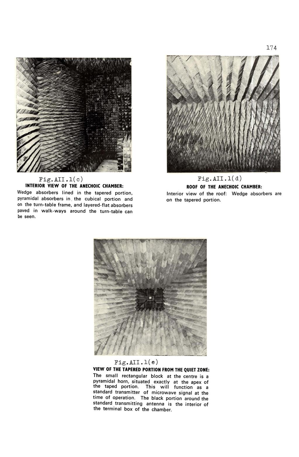
5 A tapered geometry straightens the wavefront much faster than the rectangular geometry as shown in diagram AII.l(b)(86) 2. The tapered geometry results in a smaller surface area which in turn, reduces the quantity of absorbing material required to cover it,and hence the cost. Fig.AII.l(a) shows the dimensions and the main features of the chamber. An E.M.I. shielding is provided to the chamber to avoid coupling between the interior and the external regions. Aluminium sheets of gauge 28 were employed for this purpose. A view of the different portions of the chamber is shown in Figs.AII.l(c), (6) and (e). The antenna positioner kept inside the chamber is fully automatic and it has got remote control option. AII.2 Evaluation of the Chamber AII.2(i) Reflectivity of the Material Used Prior to the construction of the anechoic chamber, the absorbing material to be used was tested to ensure its suitability. The Arch method was employed for this(87) evaluation. Fig.AII.2(i)(a) is a schematic diagram of this set up. As shown in the diagram, the transmitting and receiving horns are arranged along the arc of a circle,
6 Rectangular Chamber Tapered Chamber i i J /'' r i -i / /-/ // I /. // / *, Fig.AII.l(b) Propagation of wavefront in rectangular and tapered chambers. 0 / (I lltllllllllllllaaaaaaaaaaaaaaaaaiaa.%y Fig.AII.2(i)(a) Schematic diagram of the experimental set up for Arch Method used to test absorber samples. a is the angle of incidence. 173
7
8 175 both pointing towards its centre. A conducting sheet is kept at the centre of the arc, the transmitting and receiving horn making an angle a with the normal to line at the centre. The reflected power is noted as PO. This is the reference power. The conducting sheet is then replaced with absorbing material, covering the same area as the sheet. Due to the absorption by the material, the reflected power in this case will be much smaller. Let this be Pr. The reflectivity of the material can be calculated as Q PI R db = lo 10 log "- PodB. The advantage of this method is that the reflectivity at different angles of incidence can be determined very easily. The reflectivity values obtained for the large and small pyramidal absorbers were -30 db and -27 db rcspectively.far the flat layered and wedge type absorbers, the reflectivity was found to be -20 db and -25 db respectively. AIl.2(ii) Measurement of Chamber Reflectivity while making antenna measurements, the test antenna is kept at the quiet zone in an anechoic chamber. The quiet zone is the region inside an anechoic chamber, where the reflection from the chamber surfaces are below
9 176 the direct radiation from the transmitter by a certain specified amount. In other words, the quiet zone is the region which is free from reflected energy and hence an undistorted wavefront will be available. Generally, it is a spherical volume, the centre of which falls on the chamber axis. This region occurs at some distance from chamber wall, and is centered about the antenna stand. The chamber reflectivity is defined as the average reflectivity level measured in the quiet zone. Of the many different techniques for measuring the reflectivity(88 89) the antenna pattern comparison technique was employed since it is the most widely accepted and convenient one. Moreover, this technique gives an idea about the quality of the chamber, because the small reflection depict themselves as perturbation in the antenna patterns. Fig.AII.2(ii)(a) is a schematic diagram of the experimental set up. The transmitting antenna is kept at the apex of the tapered portion. The receiving antenna is mounted on the antenna turnstable and is kept at the centre of the quiet zone. The receiving and transmitting antennas were standard pyramidal horns. The radiation pattern of the receiving antenna was plotted for a 3600 scan. This was taken as the reference pattern. The turn-table was moved through a distance of 15 cms to a new position, along
10 I H > r " i _'. -4 _ _ 7 Fig.AII.2(ii)(a) Experimental set up used for measuring chamber reflectivity. 1 - Gunn power supply, 2 - Gunn Source, 3 - Isolator, 4 - Directional coupler. O. l H) t N 50 cms " ~41 '7 13 off centre cms 5. off centre ;?t i Reference off_centre 45-+q_ 45 * 1 r PM 1 * 1 * I 1 I O 5O 1OO Angle (deg.)- -+» AII.2(ii)(b) Radiation pattern plotted for pattern comparison.method of evaluation. 177
11 178 a direction perpendicular to the chamber axis. The radiation pattern of the same antenna at this new position is superimposed over the reference pattern, so that their main lobe peaks coincide. This is repeated at different positions along transverse and longitudinal directions from the centre of the quiet zone. Fig.AII.2(ii)(b) shows some of the patterns recorded by the above method. Here it is seen that at pattern levels well below the main lobe peaks, there exist differences between the two patterns at reference and new positions. As the patterns are plotted in db scale, the difference between the two patterns at specified pattern levels, say -l5db, -2OdB, -25dB etc., below the main lobe peak are noted and plotted as a function of the distance from the centre of the quiet zone. Fig.AII.2(ii)(c) shows this deviation curve. It is seen here that this deviation curve fluctuates between maximum and minimum values. The peak to peak excursion of this deviation curve is noted at each pattern level. The chamber reflectivity can then be obtained from a standard curve described by Buckley(89), Fig.AII.2(ii)(d) has been reproduced from the above reference. The chamber reflectivity can be readily obtained from the curves presented here. The average reflectivity of this chamber, determined by this method, has been found to be 32dB at 8.7 GHZ.
12 1 O-10 e - l d if Q Fig.AII.2(ii)(c) The deviation at each reference_pattern level with radial distance between chamber centre and test point. r- 10 ~ 1 1 1O , Cms Off cent Fig,AII,2(ii)(d) The standard curve used for determining L reflectivity of quiet zone (Ref.89) I fl ; d 1* Z *A dw I I N N _Z, I Z IIISHMI ' , L IV 5 tk L J I, I A I A V V A V A V A 7 I A I V A " J Y" I j L; ii I ISTII A A 1' A * 7 uh d '@M?" IQ VI *1 i '-.1 e e v IIIEV i t L 6. 1 y t V? ' +-* 0 3 # 7 F1 1-: J A I I J I I I e l E it 1 e k l. 1 _,J_i J-L 1 no H -5 d Level corresponding to zero reflected energy (db) IiiI I 7' y' I I 7., A 179
13 180 AlI.2(iii) Measurement of Termination VSWR of the Chamber As the self impedance of the antennas have to be measured, the termination VSWR of the chamber becomes important. Under such circumstance, the chamber acts as a large free space termination. The termination VSWR of the chamber will be very small. Hence the conventional method of measuring the VSWR with a slotted section cannot be adopted, since the mismatch introduced by the probe in the slotted section itself may be of the order of the mismatch in this termination. Therefore the moving termination technique (89 92) was adopted. Here a standard pyramidal horn antenna is employed as the transmitter. The probe in the slotted section is kept stationary. The system as a whole is moved along a longitudinal axis and the probe output is recorded. The termination VSWR of the chamber is calculated from this. It may be noted here that the directivity of the horn and its positioning has an effect on the measured value of the termination VSWR. The antenna was pointed along the axis of the chamber, a manner in which the test antenna would be mounted during actual observation. The measured values of termination VSWR from different parts of the chamber were found to be below 1.05.
14 181 AII.2(iv) Amplitude Uniformity in the Chamber Reflections in a chamber can cause the field to vary in amplitude at the test antenna aperture. In order to determine the amplitude uniformity, the chamber is illuminated with a small pyramidal horn placed at the apex of the tapered portion. Another small pyramidal horn which is used as the test antenna, is mounted on the turn-table at the centre of quiet zone. The test antenna is oriented along the axis of the transmitter. The value of the received power at the above position of the test antenna is noted as the reference power level. The turn-table is moved about 15 cm from the centre in a transverse direction perpendicular to the chamber axis and the new value of power is noted. By moving the turntable from one end of the side wall to the other end, the power values are recorded at every 15 cm. The experiment is repeated by moving the test antenna along the longitudinal direction of the chamber axis and along the vertical direction from the centre of quiet zone. Fig.AII.2(iv)(a) gives the amplitude, variation along the transverse, longitudinal and vertical directions from the centre of the quiet zone. The amplitude variations measured along the transverse and vertical directions were found to be less than
15 I 1 i M In L n 4 1~ i 2 '_ 2 ls 4; * " ;_a-ids ;;, _ f _ 1 7 s ~ ~ _' ; p Fig.AII.2(iv)(a) Anplitude variation along the transverse, longitudinal and vertical directions from ' oms off centre - ->tfle centre of the quiet zone l - Transverse 0.54 I? - Longitudinal, 3 - Vertical i H L] Qjn 1, ff r 1 ; I %5l -~~r P 1r*T*~ - r - -~ * r Angle of polarization (deg.) --r Fig.AII.2(v)(a) Variation in transmission losses for different polarization of the transmitted signal 182
16 183 O.25dB in the quiet zone. The longitudinal variations were found to be slightly high (nearly 2dB) because of the R2 variation of power. AII.2(v) Measurement of Path Loss Uniformity Vertically and horizontally polarized signals should be transmitted down the chamber with the same transmission loss. For measuring the path loss uniformity, the chamber is illuminated with a small pyramidal horn. The test antenna, mounted on the turn-table, is placed at the centre of the quiet zone and oriented at O0 (on axis). The received power is recorded as the reference power. Both the transmitting and receiving antennas are rotated synchronously, on-axis maintaining the same plane of polarization from O0 to Power level at every 150 increment are recorded. Fig.AII.2(v)(a) shows the variation in transmission losses for different polarization of the transmitted signal. It can be seen that the path loss difference is within.io.2db of the reference level. This limit is considered to be satisfactory for a good anechoic chamber(87) A microwave anechoic chamber was constructed and its performance was evaluated. Some of the important chamber-performance characteristics like reflectivity of the
17 18 chamber, termination VSWR, amplitude uniformity and path loss uniformity were measured. The values obtained were found to be very well within the requirements for which the chamber was designed. These are well in match with international standards of such microwave anechoic chambers.
Absorbers and Anechoic Chamber Measurements
 Absorbers and Anechoic Chamber Measurements Zhong Chen Director, RF Engineering ETS-Lindgren 1301 Arrow Point Dr. Cedar Park, TX, 78613 Zhong.chen@ets-lindgren.com SUMMARY Absorber Overviews Absorber Materials
NTT DOCOMO Technical Journal. Method for Measuring Base Station Antenna Radiation Characteristics in Anechoic Chamber. 1.
 Base Station Antenna Directivity Gain Method for Measuring Base Station Antenna Radiation Characteristics in Anechoic Chamber Base station antennas tend to be long compared to the wavelengths at which
Introduction Antenna Ranges Radiation Patterns Gain Measurements Directivity Measurements Impedance Measurements Polarization Measurements Scale
 Chapter 17 : Antenna Measurement Introduction Antenna Ranges Radiation Patterns Gain Measurements Directivity Measurements Impedance Measurements Polarization Measurements Scale Model Measurements 1 Introduction
Reflectivity Measurements of Commercial Absorbers in the GHz Range
 Reflectivity Measurements of Commercial Absorbers in the 2 6 GHz Range Jussi Säily, Juha Mallat, Antti V. Räisänen MilliLab, Radio Laboratory, Helsinki University of Technology P.O. Box 3, FIN-215 HUT,
WIESON TECHNOLOGIES CO., LTD.
 WIESON 3D CHAMBER TEST REPORT G121HT632-1 Page 1 of 2 I. Summary: This report to account for the measurement setup and result of the Antenna. The measurement setup includes s-parameter, pattern, and gain
BHARATHIDASAN ENGINEERING COLLEGE NATTARAMPALLI Frequently Asked Questions (FAQ) Unit 1
 Unit 1") BHARATHIDASAN ENGINEERING COLLEGE NATTARAMPALLI 635854 Frequently Asked Questions (FAQ) Unit 1 Degree / Branch : B.E / ECE Sem / Year : 3 rd / 6 th Sub Name : Antennas & Wave Propagation Sub Code : EC6602
BHARATHIDASAN ENGINEERING COLLEGE NATTARAMPALLI 635854 Frequently Asked Questions (FAQ) Unit 1 Degree / Branch : B.E / ECE Sem / Year : 3 rd / 6 th Sub Name : Antennas & Wave Propagation Sub Code : EC6602
Absorbers and Anechoic Chamber Measurements
 Absorbers and Anechoic Chamber Measurements Zhong Chen Director, RF Engineering ETS-Lindgren 1301 Arrow Point Dr. Cedar Park, TX, 78613 Zhong.chen@ets-lindgren.com SUMMARY Absorber Overview Absorber Materials
Chapter-9 CONCLUSIONS AND FUTURE SCOPE
 Chapter-9 CONCLUSIONS AND FUTURE SCOPE 9.1 CONCLUSIONS This thesis presented a detailed study about six different new antenna designs developed to demonstrate the reconfigurable concept employing electrical
Exercise 1-3. Radar Antennas EXERCISE OBJECTIVE DISCUSSION OUTLINE DISCUSSION OF FUNDAMENTALS. Antenna types
 Exercise 1-3 Radar Antennas EXERCISE OBJECTIVE When you have completed this exercise, you will be familiar with the role of the antenna in a radar system. You will also be familiar with the intrinsic characteristics
Further Refining and Validation of RF Absorber Approximation Equations for Anechoic Chamber Predictions
 Further Refining and Validation of RF Absorber Approximation Equations for Anechoic Chamber Predictions Vince Rodriguez, NSI-MI Technologies, Suwanee, Georgia, USA, vrodriguez@nsi-mi.com Abstract Indoor
Dr. John S. Seybold. November 9, IEEE Melbourne COM/SP AP/MTT Chapters
 Antennas Dr. John S. Seybold November 9, 004 IEEE Melbourne COM/SP AP/MTT Chapters Introduction The antenna is the air interface of a communication system An antenna is an electrical conductor or system
GAIN COMPARISON MEASUREMENTS IN SPHERICAL NEAR-FIELD SCANNING
 GAIN COMPARISON MEASUREMENTS IN SPHERICAL NEAR-FIELD SCANNING ABSTRACT by Doren W. Hess and John R. Jones Scientific-Atlanta, Inc. A set of near-field measurements has been performed by combining the methods
Using Frequency Diversity to Improve Measurement Speed Roger Dygert MI Technologies, 1125 Satellite Blvd., Suite 100 Suwanee, GA 30024
 Using Frequency Diversity to Improve Measurement Speed Roger Dygert MI Technologies, 1125 Satellite Blvd., Suite 1 Suwanee, GA 324 ABSTRACT Conventional antenna measurement systems use a multiplexer or
A COMPOSITE NEAR-FIELD SCANNING ANTENNA RANGE FOR MILLIMETER-WAVE BANDS
 A COMPOSITE NEAR-FIELD SCANNING ANTENNA RANGE FOR MILLIMETER-WAVE BANDS Doren W. Hess dhess@mi-technologies.com John McKenna jmckenna@mi-technologies.com MI-Technologies 1125 Satellite Boulevard Suite
Electromagnetic Compatibility ( EMC )
") Electromagnetic Compatibility ( EMC ) Introduction EMC Testing 1-2 -1 Agenda System Radiated Interference Test System Conducted Interference Test 1-2 -2 System Radiated Interference Test Open-Area Test
Electromagnetic Compatibility ( EMC ) Introduction EMC Testing 1-2 -1 Agenda System Radiated Interference Test System Conducted Interference Test 1-2 -2 System Radiated Interference Test Open-Area Test
EC ANTENNA AND WAVE PROPAGATION
 EC6602 - ANTENNA AND WAVE PROPAGATION FUNDAMENTALS PART-B QUESTION BANK UNIT 1 1. Define the following parameters w.r.t antenna: i. Radiation resistance. ii. Beam area. iii. Radiation intensity. iv. Directivity.
ANECHOIC CHAMBER EVALUATION
 ANECHOIC CHAMBER EVALUATION Antenna Measurement Techniques Association Conference October 3 - October 7, 1994 Karl Haner Nearfield Systems Inc. 1330 E. 223rd Street Bldg.524 Carson, CA 90745 USA (310)
Semi Anechoic Chamber (SAC)
") 1 of 9 Semi Anechoic Chamber (SAC) Approximate Dimensions of 3m Semi Anechoic Chamber (SAC) Length: 10m Width: 9m Height: 9m Frequency range of Semi Anechoic Chamber: 9 KHz to 40 GHz Emission test (EMI):
1 of 9 Semi Anechoic Chamber (SAC) Approximate Dimensions of 3m Semi Anechoic Chamber (SAC) Length: 10m Width: 9m Height: 9m Frequency range of Semi Anechoic Chamber: 9 KHz to 40 GHz Emission test (EMI):
Antenna Theory and Design
 Antenna Theory and Design Antenna Theory and Design Associate Professor: WANG Junjun 王珺珺 School of Electronic and Information Engineering, Beihang University F1025, New Main Building wangjunjun@buaa.edu.cn
Antenna Measurement Uncertainty Method for Measurements in Compact Antenna Test Ranges
 Antenna Measurement Uncertainty Method for Measurements in Compact Antenna Test Ranges Stephen Blalock & Jeffrey A. Fordham MI Technologies Suwanee, Georgia, USA Abstract Methods for determining the uncertainty
Millimetre Spherical Wave Antenna Pattern Measurements at NPL. Philip Miller May 2009
 Millimetre Spherical Wave Antenna Pattern Measurements at NPL Philip Miller May 2009 The NPL Spherical Range The NPL Spherical Range is a conventional spherical range housed within a 15 m by 7.5 m by 7.5
Antennas & wave Propagation ASSIGNMENT-I
 Shri Vishnu Engineering College for Women :: Bhimavaram Department of Electronics & Communication Engineering Antennas & wave Propagation 1. Define the terms: i. Antenna Aperture ii. Beam Width iii. Aperture
Technical Note
 3D RECOflO C Technical Note 1967-47 A. Sotiropoulos X-Band Cylindrical Lens Antenna 26 October 1967 Lincoln Laboratory MAS TTS INSTITUTE OF TECHNOLOGY m Lexington, Massachusetts The work reported in.this
ANTENNA INTRODUCTION / BASICS
 ANTENNA INTRODUCTION / BASICS RULES OF THUMB: 1. The Gain of an antenna with losses is given by: 2. Gain of rectangular X-Band Aperture G = 1.4 LW L = length of aperture in cm Where: W = width of aperture
CHAPTER 2 MICROSTRIP REFLECTARRAY ANTENNA AND PERFORMANCE EVALUATION
 43 CHAPTER 2 MICROSTRIP REFLECTARRAY ANTENNA AND PERFORMANCE EVALUATION 2.1 INTRODUCTION This work begins with design of reflectarrays with conventional patches as unit cells for operation at Ku Band in
Conservation of energy during the reflection and transmission of microwaves
 Related topics Microwaves, electromagnetic waves, reflection, transmission, polarisation, conservation of energy, conservation laws Principle When electromagnetic waves impinge on an obstacle, reflection,
CHAPTER 5 PRINTED FLARED DIPOLE ANTENNA
 CHAPTER 5 PRINTED FLARED DIPOLE ANTENNA 5.1 INTRODUCTION This chapter deals with the design of L-band printed dipole antenna (operating frequency of 1060 MHz). A study is carried out to obtain 40 % impedance
Colubris Networks. Antenna Guide
 Colubris Networks Antenna Guide Creation Date: February 10, 2006 Revision: 1.0 Table of Contents 1. INTRODUCTION... 3 2. ANTENNA TYPES... 3 2.1. OMNI-DIRECTIONAL ANTENNA... 3 2.2. DIRECTIONAL ANTENNA...
Aperture Antennas. Reflectors, horns. High Gain Nearly real input impedance. Huygens Principle
 Antennas 97 Aperture Antennas Reflectors, horns. High Gain Nearly real input impedance Huygens Principle Each point of a wave front is a secondary source of spherical waves. 97 Antennas 98 Equivalence
PHYS2090 OPTICAL PHYSICS Laboratory Microwaves
 PHYS2090 OPTICAL PHYSICS Laboratory Microwaves Reference Hecht, Optics, (Addison-Wesley) 1. Introduction Interference and diffraction are commonly observed in the optical regime. As wave-particle duality
Non-Ideal Quiet Zone Effects on Compact Range Measurements
 Non-Ideal Quiet Zone Effects on Compact Range Measurements David Wayne, Jeffrey A. Fordham, John McKenna MI Technologies Suwanee, Georgia, USA Abstract Performance requirements for compact ranges are typically
KULLIYYAH OF ENGINEERING
 KULLIYYAH OF ENGINEERING DEPARTMENT OF ELECTRICAL & COMPUTER ENGINEERING ANTENNA AND WAVE PROPAGATION LABORATORY (ECE 4103) EXPERIMENT NO 3 RADIATION PATTERN AND GAIN CHARACTERISTICS OF THE DISH (PARABOLIC)
ANECHOIC CHAMBER DIAGNOSTIC IMAGING
 ANECHOIC CHAMBER DIAGNOSTIC IMAGING Greg Hindman Dan Slater Nearfield Systems Incorporated 1330 E. 223rd St. #524 Carson, CA 90745 USA (310) 518-4277 Abstract Traditional techniques for evaluating the
INDOOR AUTOMATIC F-16 FIRE CONTROL ANTENNA AND RADOME TEST FACILITIES
 INDOOR AUTOMATIC F-16 FIRE CONTROL ANTENNA AND RADOME TEST FACILITIES ABSTRACT by Joseph J. Anderson MI Technologies was selected by the United States Air Force to design and install a complete turn-key
Chapter 2. Fundamental Properties of Antennas. ECE 5318/6352 Antenna Engineering Dr. Stuart Long
 Chapter Fundamental Properties of Antennas ECE 5318/635 Antenna Engineering Dr. Stuart Long 1 IEEE Standards Definition of Terms for Antennas IEEE Standard 145-1983 IEEE Transactions on Antennas and Propagation
MICROWAVE AND RADAR LAB (EE-322-F) LAB MANUAL VI SEMESTER
 LAB MANUAL VI SEMESTER") 1 MICROWAVE AND RADAR LAB (EE-322-F) MICROWAVE AND RADAR LAB (EE-322-F) LAB MANUAL VI SEMESTER RAO PAHALD SINGH GROUP OF INSTITUTIONS BALANA(MOHINDERGARH)123029 Department Of Electronics and Communication
1 MICROWAVE AND RADAR LAB (EE-322-F) MICROWAVE AND RADAR LAB (EE-322-F) LAB MANUAL VI SEMESTER RAO PAHALD SINGH GROUP OF INSTITUTIONS BALANA(MOHINDERGARH)123029 Department Of Electronics and Communication
Estimating Measurement Uncertainties in Compact Range Antenna Measurements
 Estimating Measurement Uncertainties in Compact Range Antenna Measurements Stephen Blalock & Jeffrey A. Fordham MI Technologies Suwanee, Georgia, USA sblalock@mitechnologies.com jfordham@mitechnolgies.com
Sensor and Simulation Notes Note 548 October 2009
 Sensor and Simulation Notes Note 548 October 009 Design of a rectangular waveguide narrow-wall longitudinal-aperture array using microwave network analysis Naga R. Devarapalli, Carl E. Baum, Christos G.
Test specification: Section (e)(1), Radiated emissions below 40 GHz Test procedure: ANSI C63.4, Sections 8.3.2, 13.2, 13.4 Test mode: Compliance
(1), Radiated emissions below 40 GHz Test procedure: ANSI C63.4, Sections 8.3.2, 13.2, 13.4 Test mode: Compliance") Test specification: Section 15.253(e)(1), Radiated emissions below 40 GHz Test procedure: ANSI C63.4, Sections 8.3.2, 13.2, 13.4 Plot 7.2.7 Radiated emission measurements at frequency 7280 MHz Low channel
Test specification: Section 15.253(e)(1), Radiated emissions below 40 GHz Test procedure: ANSI C63.4, Sections 8.3.2, 13.2, 13.4 Plot 7.2.7 Radiated emission measurements at frequency 7280 MHz Low channel
Microwave Optics. Department of Physics & Astronomy Texas Christian University, Fort Worth, TX. January 16, 2014
 Microwave Optics Department of Physics & Astronomy Texas Christian University, Fort Worth, TX January 16, 2014 1 Introduction Optical phenomena may be studied at microwave frequencies. Visible light has
TRANSMITTING ANTENNA WITH DUAL CIRCULAR POLARISATION FOR INDOOR ANTENNA MEASUREMENT RANGE
 TRANSMITTING ANTENNA WITH DUAL CIRCULAR POLARISATION FOR INDOOR ANTENNA MEASUREMENT RANGE Michal Mrnka, Jan Vélim Doctoral Degree Programme (2), FEEC BUT E-mail: xmrnka01@stud.feec.vutbr.cz, velim@phd.feec.vutbr.cz
RECOMMENDATION ITU-R S.1257
 Rec. ITU-R S.157 1 RECOMMENDATION ITU-R S.157 ANALYTICAL METHOD TO CALCULATE VISIBILITY STATISTICS FOR NON-GEOSTATIONARY SATELLITE ORBIT SATELLITES AS SEEN FROM A POINT ON THE EARTH S SURFACE (Questions
INSTITUTE OF AERONAUTICAL ENGINEERING Dundigal, Hyderabad ELECTRONICS AND COMMUNIACTION ENGINEERING QUESTION BANK
 INSTITUTE OF AERONAUTICAL ENGINEERING Dundigal, Hyderabad - 500 04 ELECTRONICS AND COMMUNIACTION ENGINEERING QUESTION BANK Course Name : Antennas and Wave Propagation (AWP) Course Code : A50418 Class :
Antenna Fundamentals Basics antenna theory and concepts
 Antenna Fundamentals Basics antenna theory and concepts M. Haridim Brno University of Technology, Brno February 2017 1 Topics What is antenna Antenna types Antenna parameters: radiation pattern, directivity,
INTERNATIONAL STANDARD
 INTERNATIONAL STANDARD IEC 60489-1 1983 AMENDMENT 2 1999-05 Amendment 2 Methods of measurement for radio equipment used in the mobile services Part 1: General definitions and standard conditions of measurement
3-2 Evaluation of Uncertainty of Horn Antenna Calibration with the Frequency range of 1 GHz to 18 GHz.
 3-2 Evaluation of Uncertainty of Horn Antenna Calibration with the Frequency range of 1 GHz to 18 GHz. SAKASAI Makoto, MASUZAWA Hiroshi, FUJII Katsumi, SUZUKI Akira, KOIKE Kunimasa, and YAMANAKA Yukio
A BROADBAND POLARIZATION SELECTABLE FEED FOR COMPACT RANGE APPLICATIONS
 A BROADBAND POLARIZATION SELECTABLE FEED FOR COMPACT RANGE APPLICATIONS Carl W. Sirles ATDS Howland 454 Atwater Court, Suite 17 Buford, GA 3518 Abstract Many aircraft radome structures are designed to
7. Experiment K: Wave Propagation
 7. Experiment K: Wave Propagation This laboratory will be based upon observing standing waves in three different ways, through coaxial cables, in free space and in a waveguide. You will also observe some
HOW TO CHOOSE AN ANTENNA RANGE CONFIGURATION
 HOW TO CHOOSE AN ANTENNA RANGE CONFIGURATION Donnie Gray Nearfield Systems, Inc. 1330 E. 223 rd St, Bldg 524 Carson, CA 90745 (310) 518-4277 dgray@nearfield.com Abstract Choosing the proper antenna range
Circularly Polarized Post-wall Waveguide Slotted Arrays
 Circularly Polarized Post-wall Waveguide Slotted Arrays Hisahiro Kai, 1a) Jiro Hirokawa, 1 and Makoto Ando 1 1 Department of Electrical and Electric Engineering, Tokyo Institute of Technology 2-12-1 Ookayama
LE/ESSE Payload Design
 LE/ESSE4360 - Payload Design 4.3 Communications Satellite Payload - Hardware Elements Earth, Moon, Mars, and Beyond Dr. Jinjun Shan, Professor of Space Engineering Department of Earth and Space Science
Main features. System configurations. I Compact Range SOLUTION FOR
 Compact Range + Direct far-field measurement of electrically large antennas SOLUTION FOR Antenna measurement Radome measurement RCS measurement A Compact Range makes direct far-field measurement of electrically
Model 3140B BiConiLog Antenna User Manual
 Model 3140B BiConiLog Antenna User Manual Model 3140B mounted onto a 7-TR tripod (not included) ETS-Lindgren L.P. reserves the right to make changes to any product described herein in order to improve
MITIGATING INTERFERENCE ON AN OUTDOOR RANGE
 MITIGATING INTERFERENCE ON AN OUTDOOR RANGE Roger Dygert MI Technologies Suwanee, GA 30024 rdygert@mi-technologies.com ABSTRACT Making measurements on an outdoor range can be challenging for many reasons,
33 BY 16 NEAR-FIELD MEASUREMENT SYSTEM
 33 BY 16 NEAR-FIELD MEASUREMENT SYSTEM ABSTRACT Nearfield Systems Inc. (NSI) has delivered the world s largest vertical near-field measurement system. With a 30m by 16m scan area and a frequency range
Experiment 19. Microwave Optics 1
 Experiment 19 Microwave Optics 1 1. Introduction Optical phenomena may be studied at microwave frequencies. Using a three centimeter microwave wavelength transforms the scale of the experiment. Microns
The Design of an Automated, High-Accuracy Antenna Test Facility
 The Design of an Automated, High-Accuracy Antenna Test Facility T. JUD LYON, MEMBER, IEEE, AND A. RAY HOWLAND, MEMBER, IEEE Abstract This paper presents the step-by-step application of proven far-field
MISSION TO MARS - IN SEARCH OF ANTENNA PATTERN CRATERS
 MISSION TO MARS - IN SEARCH OF ANTENNA PATTERN CRATERS Greg Hindman & Allen C. Newell Nearfield Systems Inc. 197 Magellan Drive Torrance, CA 92 ABSTRACT Reflections in anechoic chambers can limit the performance
Fundamentals. Senior Project Manager / AEO Taiwan. Philip Chang
 mmwave OTA Fundamentals Senior Project Manager / AEO Taiwan Philip Chang L A R G E LY D R I V E N B Y N E W W I R E L E S S T E C H N O L O G I E S A N D F R E Q U E N C Y B A N D S 1. Highly integrated
REVERBERATION CHAMBER FOR EMI TESTING
 1 REVERBERATION CHAMBER FOR EMI TESTING INTRODUCTION EMI Testing 1. Whether a product is intended for military, industrial, commercial or residential use, while it must perform its intended function in
Traveling Wave Antennas
 Traveling Wave Antennas Antennas with open-ended wires where the current must go to zero (dipoles, monopoles, etc.) can be characterized as standing wave antennas or resonant antennas. The current on these
HIGH ACCURACY CROSS-POLARIZATION MEASUREMENTS USING A SINGLE REFLECTOR COMPACT RANGE
 HIGH ACCURACY CROSS-POLARIZATION MEASUREMENTS USING A SINGLE REFLECTOR COMPACT RANGE Christopher A. Rose Microwave Instrumentation Technologies 4500 River Green Parkway, Suite 200 Duluth, GA 30096 Abstract
ELEC4604. RF Electronics. Experiment 1
 ELEC464 RF Electronics Experiment ANTENNA RADATO N PATTERNS. ntroduction The performance of RF communication systems depend critically on the radiation characteristics of the antennae it employs. These
Performance Simulation of Pyramidal and Wedge Microwave Absorbers
 2009 Third Asia International Conference on Modelling & Simulation Performance Simulation of Pyramidal and Wedge Microwave Absorbers H. Nornikman, P.J Soh, A.A.H Azremi, M.S Anuar School of Computer and
ANTENNA INTRODUCTION / BASICS
 Rules of Thumb: 1. The Gain of an antenna with losses is given by: G 0A 8 Where 0 ' Efficiency A ' Physical aperture area 8 ' wavelength ANTENNA INTRODUCTION / BASICS another is:. Gain of rectangular X-Band
UNIT Explain the radiation from two-wire. Ans: Radiation from Two wire
 UNIT 1 1. Explain the radiation from two-wire. Radiation from Two wire Figure1.1.1 shows a voltage source connected two-wire transmission line which is further connected to an antenna. An electric field
Performance of Roadside Sound Barriers with Sound Absorbing Edges
 Performance of Roadside Sound Barriers with Sound Absorbing Edges Diffracted Path Transmitted Path Interference Source Luc Mongeau, Sanghoon Suh, and J. Stuart Bolton School of Mechanical Engineering,
Electromagnetic Effects, original release, dated 31 October Contents: 17 page document plus 13 Figures. Enclosure (1)
") Electromagnetic Effects, original release, dated 31 October 2005 Contents: 17 page document plus 13 Figures Enclosure (1) Electromagnetic effects. 1. Purpose. To ensure that the addition of fiber optic
Electromagnetic Effects, original release, dated 31 October 2005 Contents: 17 page document plus 13 Figures Enclosure (1) Electromagnetic effects. 1. Purpose. To ensure that the addition of fiber optic
Chapter 5. Array of Star Spirals
 Chapter 5. Array of Star Spirals The star spiral was introduced in the previous chapter and it compared well with the circular Archimedean spiral. This chapter will examine the star spiral in an array
A DUAL-PORTED PROBE FOR PLANAR NEAR-FIELD MEASUREMENTS
 A DUAL-PORTED PROBE FOR PLANAR NEAR-FIELD MEASUREMENTS W. Keith Dishman, Doren W. Hess, and A. Renee Koster ABSTRACT A dual-linearly polarized probe developed for use in planar near-field antenna measurements
Microstrip Antennas Integrated with Horn Antennas
 53 Microstrip Antennas Integrated with Horn Antennas Girish Kumar *1, K. P. Ray 2 and Amit A. Deshmukh 1 1. Department of Electrical Engineering, I.I.T. Bombay, Powai, Mumbai 400 076, India Phone: 91 22
Comparative study, building, measurement and simulation of two wi-fi slotted waveguide antennas made by a rectangular guide
 Comparative study, building, measurement and simulation of two wi-fi slotted waveguide antennas made by a rectangular guide João Filipe Tavares Rodrigues Instituto Superior Técnico Avenida Rovisco Pais,
PLANE-WAVE SYNTHESIS FOR COMPACT ANTENNA TEST RANGE BY FEED SCANNING
 Progress In Electromagnetics Research M, Vol. 22, 245 258, 2012 PLANE-WAVE SYNTHESIS FOR COMPACT ANTENNA TEST RANGE BY FEED SCANNING H. Wang 1, *, J. Miao 2, J. Jiang 3, and R. Wang 1 1 Beijing Huahang
Practical Considerations for Radiated Immunities Measurement using ETS-Lindgren EMC Probes
 Practical Considerations for Radiated Immunities Measurement using ETS-Lindgren EMC Probes Detectors/Modulated Field ETS-Lindgren EMC probes (HI-6022/6122, HI-6005/6105, and HI-6053/6153) use diode detectors
Experiment 12: Microwaves
 MASSACHUSETTS INSTITUTE OF TECHNOLOGY Department of Physics 8.02 Spring 2005 OBJECTIVES Experiment 12: Microwaves To observe the polarization and angular dependence of radiation from a microwave generator
Oblique incidence measurement setup for millimeter wave EM absorbers
 Oblique incidence measurement setup for millimeter wave EM absorbers Shinichiro Yamamoto a) and Kenichi Hatakeyama Graduate School of Engineering, University of Hyogo, 2167 Shosha, Himeji-shi, Hyogo 671
THE ELECTROMAGNETIC FIELD THEORY. Dr. A. Bhattacharya
 1 THE ELECTROMAGNETIC FIELD THEORY Dr. A. Bhattacharya The Underlying EM Fields The development of radar as an imaging modality has been based on power and power density It is important to understand some
Study of the Effect of RCS on Radar Detection
 Study of the Effect of RCS on Radar Detection Dr. Haitham Kareem Ali (Assistant Professor) Technical College of Engineering, Sulaimani Polytechnic University, Kurdistan Region, Iraq doi: 10.19044/esj.2017.v13n15p148
The Benefits of BEC s Antenna Design
 The Benefits of BEC s Antenna Design Overview The explosive growth of wireless data communications is fast emerging with high peak data rates, which require superior antenna performance and design to support
Rec. ITU-R F RECOMMENDATION ITU-R F *
 Rec. ITU-R F.162-3 1 RECOMMENDATION ITU-R F.162-3 * Rec. ITU-R F.162-3 USE OF DIRECTIONAL TRANSMITTING ANTENNAS IN THE FIXED SERVICE OPERATING IN BANDS BELOW ABOUT 30 MHz (Question 150/9) (1953-1956-1966-1970-1992)
An Introduction to Antennas
 May 11, 010 An Introduction to Antennas 1 Outline Antenna definition Main parameters of an antenna Types of antennas Antenna radiation (oynting vector) Radiation pattern Far-field distance, directivity,
Broadband aperture-coupled equilateral triangular microstrip array antenna
 Indian Journal of Radio & Space Physics Vol. 38, June 2009, pp. 174-179 Broadband aperture-coupled equilateral triangular microstrip array antenna S N Mulgi $,*, G M Pushpanjali, R B Konda, S K Satnoor
A CYLINDRICAL NEAR-FIELD VS. SPHERICAL NEAR-FIELD ANTENNA TEST COMPARISON
 A CYLINDRICAL NEAR-FIELD VS. SPHERICAL NEAR-FIELD ANTENNA TEST COMPARISON Jeffrey Fordham VP, Sales and Marketing MI Technologies, 4500 River Green Parkway, Suite 200 Duluth, GA 30096 jfordham@mi-technologies.com
RESEARCH AND DESIGN OF QUADRUPLE-RIDGED HORN ANTENNA. of Aeronautics and Astronautics, Nanjing , China
 Progress In Electromagnetics Research Letters, Vol. 37, 21 28, 2013 RESEARCH AND DESIGN OF QUADRUPLE-RIDGED HORN ANTENNA Jianhua Liu 1, Yonggang Zhou 1, 2, *, and Jun Zhu 1 1 College of Electronic and
Mutual Coupling between Two Patches using Ideal High Impedance Surface
 International Journal of Electronics and Communication Engineering. ISSN 0974-2166 Volume 4, Number 3 (2011), pp. 287-293 International Research Publication House http://www.irphouse.com Mutual Coupling
RECOMMENDATION ITU-R F *
 Rec. ITU-R F.699-6 1 RECOMMENATION ITU-R F.699-6 * Reference radiation patterns for fixed wireless system antennas for use in coordination studies and interference assessment in the frequency range from
Chapter Ray and Wave Optics
 109 Chapter Ray and Wave Optics 1. An astronomical telescope has a large aperture to [2002] reduce spherical aberration have high resolution increase span of observation have low dispersion. 2. If two
Chapter 41 Deep Space Station 13: Venus
 Chapter 41 Deep Space Station 13: Venus The Venus site began operation in Goldstone, California, in 1962 as the Deep Space Network (DSN) research and development (R&D) station and is named for its first
Large E Field Generators in Semi-anechoic Chambers for Full Vehicle Immunity Testing
 Large E Field Generators in Semi-anechoic Chambers for Full Vehicle Immunity Testing Vince Rodriguez ETS-Lindgren, Inc. Abstract Several standards recommend the use of transmission line systems (TLS) as
The Basics of Patch Antennas, Updated
 The Basics of Patch Antennas, Updated By D. Orban and G.J.K. Moernaut, Orban Microwave Products www.orbanmicrowave.com Introduction This article introduces the basic concepts of patch antennas. We use
Welcome to AntennaSelect Volume 4 November Where is the RFR at my site?
 Welcome to AntennaSelect Volume 4 November 2013 Welcome to Volume 4 of our newsletter AntennaSelect. Each month we will be giving you an under the radome look at antenna and RF technology. If there are
Conclusion and Future Scope
 Chapter 8 8.1 Conclusions The study of planar Monopole, Slot, Defected Ground, and Fractal antennas has been carried out to achieve the research objectives. These UWB antenna designs are characterised
MEASUREMENT OF THE ODIN TELESCOPE AT 119 GHz WITH A HOLOGRAM TYPE CATR
 MEASUREMENT OF THE ODIN TELESCOPE AT 119 GHz WITH A HOLOGRAM TYPE CATR J. Ala-Laurinaho 1, T. Hirvonen 1, P. Piironen 1, A. Lehto 1, J. Tuovinen 1, A. V. Räisänen 1, U. Frisk 2 1 Radio Laboratory, Helsinki
Chapter 15: Radio-Wave Propagation
 Chapter 15: Radio-Wave Propagation MULTIPLE CHOICE 1. Radio waves were first predicted mathematically by: a. Armstrong c. Maxwell b. Hertz d. Marconi 2. Radio waves were first demonstrated experimentally
Antennas & Measurement of its parameters
 Antennas & Measurement of its parameters Chandana Viswanadham SDGM (D&E), Bharat Electronics, IE, Nacharam, Hyderabad 500 076 ABSTRACT As all of us aware, a communication system comprises Transmitter,
MICROWAVE MICROWAVE TRAINING BENCH COMPONENT SPECIFICATIONS:
 Microwave section consists of Basic Microwave Training Bench, Advance Microwave Training Bench and Microwave Communication Training System. Microwave Training System is used to study all the concepts of
Accuracy Estimation of Microwave Holography from Planar Near-Field Measurements
 Accuracy Estimation of Microwave Holography from Planar Near-Field Measurements Christopher A. Rose Microwave Instrumentation Technologies River Green Parkway, Suite Duluth, GA 9 Abstract Microwave holography
Comparison of Different Kinds of Edge Tapering System in Microwave Power Transmission
 INFORMATION AND COMMUNICATION ENGINEERS SPS6-1 (6) Comparison of Different Kinds of Edge Tapering System in Microwave Power Transmission A.K.M.Baki a), K.Hashimoto b), N. Shinohara c), H. Matsumoto d),
EMG4066:Antennas and Propagation Exp 1:ANTENNAS MMU:FOE. To study the radiation pattern characteristics of various types of antennas.
 OBJECTIVES To study the radiation pattern characteristics of various types of antennas. APPARATUS Microwave Source Rotating Antenna Platform Measurement Interface Transmitting Horn Antenna Dipole and Yagi
Aperture Efficiency of Integrated-Circuit Horn Antennas
 First International Symposium on Space Terahertz Technology Page 169 Aperture Efficiency of Integrated-Circuit Horn Antennas Yong Guo, Karen Lee, Philip Stimson Kent Potter, David Rutledge Division of