WIESON TECHNOLOGIES CO., LTD.
|
|
|
- Brian Mitchell
- 5 years ago
- Views:
Transcription

1 WIESON 3D CHAMBER TEST REPORT G121HT632-1 Page 1 of 2
2 I. Summary: This report to account for the measurement setup and result of the Antenna. The measurement setup includes s-parameter, pattern, and gain measurement. The measured data for Antenna are presented and analysis. II. S-Parameter Measurement: A. Reflection coefficient : (a) Instrument:Network Analyzer. (b) Setup: (1) Calibrate the Network Analyzer by one port calibration using O.S.L. calibration kits. (2) Connect the antenna under test to the Network Analyzer. (3) Measure the S11(reflection coefficient) shown in Fig. 1. (4) Generally, the S11 is less than 1 to ensure the 9% power into antenna and only less than 1% power back to system. Fig.1 Antenna measured in Network Analyzer Page 2 of 2

3 III. S-Parameter Measurement Result: Antenna Return loss Frequency MHz Page 3 of 2
4 Antenna VSWR Frequency MHz VSWR Page 4 of 2
 One 325 cm (W) x cm (H) x 64 cm (L) Antenna Measurement Anechoic Chamber, detailed")
5 IV. The Test Information Anechoic Chamber A. Scope This statement of work defines the requirements of a far-field antenna measurement range, which includes (1) One 325 cm (W) x cm (H) x 64 cm (L) Antenna Measurement Anechoic Chamber, detailed requirements refer section 2.. (2) One Far-field Antenna Measurement System with spinning linear CP measurement capabilities, detailed requirement refer section 3.. (3) One broad-band transmitted antenna, detailed requirements refer section 8.. (4) Three NRL-4433 standard gain antennas, detailed requirements refer section 9.. B. Antenna Measurement Anechoic Chamber Fully anechoic chamber with dimension 325 cm in width, cm in height and 64 cm in length. The quiet zone of this Chamber shall be greater than Page 5 of 2
6 7 GHz, 5 GHz, 44 GHz, 28 GHz, 16 GHz. Contractor should be aware of this anechoic chamber is going to be used for performing far-filed antenna measurement. C. Electrical specifications Frequency Range: 8 MHz to 18 GHz, Quiet zone size: >7 GHz, >5 GHz, >44 GHz, >28 GHz, >16 GHz. Quiet zone ripple: < GHz, < Field Probing Frequency Peak-to-Peak Amplitude Taper (Within specified Quiet one Area) Quiet one Size (cm) Compliant.9 GHz <.8 7 es 1.5 GHz <.6 55 es 1.8 GHz <.5 5 es 2. GHz <.4 44 es 4.8 GHz <.3 31 es 5.8 GHz <.3 28 es Page 6 of 2
7 D. Absorbers We shall design and install proper absorbers on the inner walls of the chamber to guarantee the electrical specifications. However, the absorbers height shall be no less than 24" which enables the space in the chamber to be around 23 cm (W) x 163 cm (H) x 533 cm (L). All the absorber used shall meet NRL-893 fire retardant regulations E. Far-field Antenna Measurement System We shall supply all the hardware and software which are capable of characterizing antenna radiation patterns from 3 KHz to 6 GHz or 18GHz using the existed Agilent 523A PNA-L or Agilent 83ES Vector Network Analyzer. The system shall be able to automatically measure and plot single axis amplitude and phase antenna patterns in either Cartesian or polar formats. F. Far-field measurement software The software consists of the control or data acquisition software and the data plotting software. (1) The data acquisition software shall at least be capable of the following functions: *measuring single frequency per cut - single axis (azimuth); system can automatically switch frequency at the end of a scan. *measuring data in Uni-direction or bi-direction *measuring data at least with azimuth 36 degrees. (+/- 18 degrees or -36 degrees) *real time plot in Cartesian or polar format *screen shows real time angle position Page 7 of 2
8 *system automatically calculates S/N ratio level based on measured signal fluctuation *function to set positioner zero position *operator can set data taking velocity and data sampling interval *entry to allow positioner offset to any angle (2) The data plotting software shall at least be capable of the following functions: *Editing plot data *plotting data in Cartesian, Polar or delimited ASCII output with header information *plotting data in linear or scales *normalizing data to peak (), standard gain reference (i), or no normalization *overlaying data, (drag and drop capability is preferable) *outputting data to any Windows supported printers G. Broadband Transmitted antenna We shall provide a linear-polarized broadband antenna with the specifications better than those listed hereafter in this article, Frequency: 1-18 GHz, Gain: >12 GHz, VSWR:<2,:1, Front to Back Ration > 2 H. NRL4433 Standard Gain Horns We shall provide one WR-43, WR-187 one DRH118 standard gain horns which meets the specifications of NRL-4433 report. The operating frequency of WR-43 standard gain horn is from 1.7 to 2.6 GHz, and WR-187 from 3.95 to 5.85 GHz, and DRH-118 from.8 to 18GHz. We shall also provide NRL-4433 theoretical gain curves and tables for the standard gain horns. Page 8 of 2

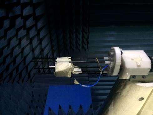
9 V. Antenna Measurement Photo Page 9 of 2
10 VI. Antenna Measurement Result Frequency (GHz) Peak Gain (i) 3D Gain (i) 3D Radiation Efficiency(%) Page 1 of 2
11 VIII. 3D Radiation Pattern of Antenna 2.4GHz pol D Pattern Far-field deg. (E-Theta Plane-Cut) pol pol Far-field deg. (E-Theta Plane-Cut) Page 11 of 2 Far-field deg. (E-Phi Plane-Cut)
12 2.GHz pol D Pattern Far-field deg. (E-Theta Plane-Cut) pol pol Far-field deg. (E-Theta Plane-Cut) Far-field deg. (E-Theta Plane-Cut) Far-field deg. (E-Phi Plane-Cut) Page 12 of 2
 pol pol 33 3 33 3 3 3 3 6 3 6 27-3 -2-1 9 27-3 -2-1 9 24 12 24 12 21 21 18 18 Far-field Pattern @Phi=9 deg.")
13 2.5GHz pol D Pattern Far-field deg. (E-Theta Plane-Cut) pol pol Far-field deg. (E-Theta Plane-Cut) Far-field deg. (E-Phi Plane-Cut) Page 13 of 2
14 5.GHz pol D Pattern Far-field deg. (E-Theta Plane-Cut) pol pol Far-field deg. (E-Theta Plane-Cut) Far-field deg. (E-Phi Plane-Cut) Page 14 of 2
15 5.25GHz pol D Pattern Far-field deg. (E-Theta Plane-Cut) pol pol Far-field deg. (E-Theta Plane-Cut) Far-field deg. (E-Phi Plane-Cut) Page of 2
16 5.35GHz pol D Pattern Far-field Phi=9 deg(e-theta Plane-Cut) Plot Peak Gain= 2.7 i; Co-Pol Efficiency: Freq: 5.35 GHz 18 Far-field deg. (E-Theta Plane-Cut) Far-field Theta=9 deg(e-phi Plane-Cut) Plot Peak Gain= -1.3 i; Co-Pol Efficiency: Freq: 5.35 GHz pol pol Far-field deg. (E-Theta Plane-Cut) 21 Far-field deg. (E-Phi Plane-Cut) Page 16 of 2
17 5.47GHz pol D Pattern Far-field deg. (E-Theta Plane-Cut) pol pol Far-field deg. (E-Theta Plane-Cut) Far-field deg. (E-Phi Plane-Cut) Page 17 of 2
18 5.6GHz pol D Pattern Far-field deg. (E-Theta Plane-Cut) pol pol Far-field deg. (E-Theta Plane-Cut) Far-field deg. (E-Phi Plane-Cut) Page 18 of 2
19 5.785GHz pol D Pattern Far-field deg. (E-Theta Plane-Cut) pol pol Far-field deg. (E-Theta Plane-Cut) Far-field deg. (E-Phi Plane-Cut) Page 19 of 2
20 5.85GHz pol D Pattern Far-field deg. (E-Theta Plane-Cut) pol pol Far-field deg. (E-Theta Plane-Cut) Far-field deg. (E-Phi Plane-Cut) Page 2 of 2
GPS Active Antenna With GPRS Measurement Report
 GPS Active Antenna With GPRS Measurement Report Summary: This report is to account for the measurement setup and results of 4x23mm and mm height GPS active antenna combined with GPRS antenna measurement.
The CReSIS Anechoic Chamber is located at: The University of Kansas. M2SEC building W 15 th St. Lawrence, KS
 The CReSIS Anechoic Chamber is located at: The University of Kansas M2SEC building 1536 W 15 th St Lawrence, KS 66045 Pattern Manual Antenna radiation pattern measurement 1. To open EMQuest, right click
A BROADBAND POLARIZATION SELECTABLE FEED FOR COMPACT RANGE APPLICATIONS
 A BROADBAND POLARIZATION SELECTABLE FEED FOR COMPACT RANGE APPLICATIONS Carl W. Sirles ATDS Howland 454 Atwater Court, Suite 17 Buford, GA 3518 Abstract Many aircraft radome structures are designed to
Main features. System configurations. I Compact Range SOLUTION FOR
 Compact Range + Direct far-field measurement of electrically large antennas SOLUTION FOR Antenna measurement Radome measurement RCS measurement A Compact Range makes direct far-field measurement of electrically
Millimetre Spherical Wave Antenna Pattern Measurements at NPL. Philip Miller May 2009
 Millimetre Spherical Wave Antenna Pattern Measurements at NPL Philip Miller May 2009 The NPL Spherical Range The NPL Spherical Range is a conventional spherical range housed within a 15 m by 7.5 m by 7.5
ETS Lindgren Anechoic Chamber
 ETS Lindgren Anechoic Chamber Provides an electromagnetically quiet environment for measuring the radiating properties of a device-undertest Enclosed by an external metallic shielding to provide isolation
SPHERICAL NEAR-FIELD SELF-COMPARISON MEASUREMENTS
 SPHERICAL NEAR-FIELD SELF-COMPARISON MEASUREMENTS Greg Hindman, Allen C. Newell Nearfield Systems Inc. 1973 Magellan Dr. Torrance, CA 952 ABSTRACT Spherical near-field measurements require an increased
BROADBAND GAIN STANDARDS FOR WIRELESS MEASUREMENTS
 BROADBAND GAIN STANDARDS FOR WIRELESS MEASUREMENTS James D. Huff Carl W. Sirles The Howland Company, Inc. 4540 Atwater Court, Suite 107 Buford, Georgia 30518 USA Abstract Total Radiated Power (TRP) and
APPLICATIONS OF PORTABLE NEAR-FIELD ANTENNA MEASUREMENT SYSTEMS
 APPLICATIONS OF PORTABLE NEAR-FIELD ANTENNA MEASUREMENT SYSTEMS Greg Hindman Nearfield Systems Inc. 1330 E. 223rd Street Bldg. 524 Carson, CA 90745 (213) 518-4277 ABSTRACT Portable near-field measurement
A DUAL-PORTED PROBE FOR PLANAR NEAR-FIELD MEASUREMENTS
 A DUAL-PORTED PROBE FOR PLANAR NEAR-FIELD MEASUREMENTS W. Keith Dishman, Doren W. Hess, and A. Renee Koster ABSTRACT A dual-linearly polarized probe developed for use in planar near-field antenna measurements
Semi Anechoic Chamber (SAC)
") 1 of 9 Semi Anechoic Chamber (SAC) Approximate Dimensions of 3m Semi Anechoic Chamber (SAC) Length: 10m Width: 9m Height: 9m Frequency range of Semi Anechoic Chamber: 9 KHz to 40 GHz Emission test (EMI):
1 of 9 Semi Anechoic Chamber (SAC) Approximate Dimensions of 3m Semi Anechoic Chamber (SAC) Length: 10m Width: 9m Height: 9m Frequency range of Semi Anechoic Chamber: 9 KHz to 40 GHz Emission test (EMI):
Contents. EH-H21/12 Page 2 of 38
 Contents. Summary.... Date and Place of Measurements.... Description of the Test Site.... Measurements and Results..... Normalised Site Attenuation (NSA)...... Test Description...... Measurement Equipment...
Fundamentals. Senior Project Manager / AEO Taiwan. Philip Chang
 mmwave OTA Fundamentals Senior Project Manager / AEO Taiwan Philip Chang L A R G E LY D R I V E N B Y N E W W I R E L E S S T E C H N O L O G I E S A N D F R E Q U E N C Y B A N D S 1. Highly integrated
> StarLab. Multi-purpose Antenna Measurement Multi-protocol Antenna Development Linear Array Antenna Measurement OTA Testing
 TECHNOLOGY Near-field / Spherical Near-field / Cylindrical SOLUTIONS FOR Multi-purpose Antenna Measurement Multi-protocol Antenna Development Linear Array Antenna Measurement OTA Testing 18 StarLab: a
Title: Test on 5.8 GHz Band Outdoor WiFi (802.11b/g) Wireless Base Station
 Wireless Base Station") Page 20 of 51 Pages 7.5. Conducted spurious emission 7.5.1. Requirements: Clause 15.247(d). In any 100 khz bandwidth outside the frequency band in which the spread spectrum or digitally modulated intentional
Page 20 of 51 Pages 7.5. Conducted spurious emission 7.5.1. Requirements: Clause 15.247(d). In any 100 khz bandwidth outside the frequency band in which the spread spectrum or digitally modulated intentional
System configurations. Main features. I TScan SOLUTION FOR
 TScan TScan is a fast and ultra-accurate planar near-field scanner with the latest motor drive and encoder technologies. High acceleration of the linear motors for stepped and continuous mode operation
Millimeter Spherical µ-lab System from Orbit/FR
 Millimeter Spherical µ-lab System from Orbit/FR Jim Puri Sr. Applications Engineer Orbit/FR, Inc. a Microwave Vision Group company Keysight Technologies and MVG Orbit/FR Partners in Radiated Measurement
Using Frequency Diversity to Improve Measurement Speed Roger Dygert MI Technologies, 1125 Satellite Blvd., Suite 100 Suwanee, GA 30024
 Using Frequency Diversity to Improve Measurement Speed Roger Dygert MI Technologies, 1125 Satellite Blvd., Suite 1 Suwanee, GA 324 ABSTRACT Conventional antenna measurement systems use a multiplexer or
ANECHOIC CHAMBER EVALUATION
 ANECHOIC CHAMBER EVALUATION Antenna Measurement Techniques Association Conference October 3 - October 7, 1994 Karl Haner Nearfield Systems Inc. 1330 E. 223rd Street Bldg.524 Carson, CA 90745 USA (310)
A CYLINDRICAL NEAR-FIELD VS. SPHERICAL NEAR-FIELD ANTENNA TEST COMPARISON
 A CYLINDRICAL NEAR-FIELD VS. SPHERICAL NEAR-FIELD ANTENNA TEST COMPARISON Jeffrey Fordham VP, Sales and Marketing MI Technologies, 4500 River Green Parkway, Suite 200 Duluth, GA 30096 jfordham@mi-technologies.com
FCC ID: A3LSLS-BD106Q. Report No.: HCT-RF-1801-FC003. Plot Data for Output Port 2_QPSK 9 khz ~ 150 khz Middle channel 150 khz ~ 30 MHz Low channel
 Plot Data for Output Port 2_QPSK 9 khz ~ 150 khz Middle channel 150 khz ~ 30 MHz Low channel 30 MHz ~ 1 GHz Middle channel 1 GHz ~ 2.491 GHz Low channel 2.695 GHz ~ 12.75 GHz High channel 12.75 GHz ~ 26.5
SPHERICAL NEAR-FIELD MEASUREMENTS AT UHF FREQUENCIES WITH COMPLETE UNCERTAINTY ANALYSIS
 SPHERICAL NEAR-FIELD MEASUREMENTS AT UHF FREQUENCIES WITH COMPLETE UNCERTAINTY ANALYSIS Allen Newell, Patrick Pelland Nearfield Systems Inc. 19730 Magellan Drive, Torrance, CA 90502-1104 Brian Park, Ted
A COMPOSITE NEAR-FIELD SCANNING ANTENNA RANGE FOR MILLIMETER-WAVE BANDS
 A COMPOSITE NEAR-FIELD SCANNING ANTENNA RANGE FOR MILLIMETER-WAVE BANDS Doren W. Hess dhess@mi-technologies.com John McKenna jmckenna@mi-technologies.com MI-Technologies 1125 Satellite Boulevard Suite
4GHz / 6GHz Radiation Measurement System
 4GHz / 6GHz Radiation Measurement System The MegiQ Radiation Measurement System (RMS) is a compact test system that performs 3-axis radiation pattern measurement in non-anechoic spaces. With a frequency
T- DualScan. StarLab
 T- DualScan StarLab StarLab is the ultimate tool for antenna pattern measurements in laboratories and production environments where space is limited, cost is critical, and the flexibility of a portable
Test sites for EMC measurements
 Test sites for EMC measurements EMV Fachtagung 21. Januar 2014 Christophe Perrenoud www.montenaemc.ch montena emc Route de Montena 75 CH - 1728 Rossens Tel. +41 26 411 93 33 Fax +41 26 411 93 30 office.emc@montenaemc.ch
REFLECTION SUPPRESSION IN LARGE SPHERICAL NEAR-FIELD RANGE
 REFLECTION SUPPRESSION IN LARGE SPHERICAL NEAR-FIELD RANGE Greg Hindman & Allen C. Newell Nearfield Systems Inc. 1973 Magellan Drive Torrance, CA 952 ABSTRACT Reflections in antenna test ranges can often
Further Refining and Validation of RF Absorber Approximation Equations for Anechoic Chamber Predictions
 Further Refining and Validation of RF Absorber Approximation Equations for Anechoic Chamber Predictions Vince Rodriguez, NSI-MI Technologies, Suwanee, Georgia, USA, vrodriguez@nsi-mi.com Abstract Indoor
Software. Equipment. Add-ons. Accessories. Services
 T- DualScan FScan FScan is a vertical near-field planar scanner system that is a perfect solution for antenna measurement applications where a phased array, high gain, or reflector antenna is under evaluation.
Ave output power ANT 1(dBm) Ave output power ANT 2 (dbm)
 Ave output power ANT 2 (dbm)") Page 41 of 103 9.6. Test Result The test was performed with 802.11b Channel Frequency (MHz) power ANT 1(dBm) power ANT 2 (dbm) power ANT 1(mW) power ANT 2 (mw) Limits dbm / W Low 2412 7.20 7.37 5.248 5.458
Page 41 of 103 9.6. Test Result The test was performed with 802.11b Channel Frequency (MHz) power ANT 1(dBm) power ANT 2 (dbm) power ANT 1(mW) power ANT 2 (mw) Limits dbm / W Low 2412 7.20 7.37 5.248 5.458
REPORT ITU-R BT Radiation pattern characteristics of UHF * television receiving antennas
 Rep. ITU-R BT.2138 1 REPORT ITU-R BT.2138 Radiation pattern characteristics of UHF * television receiving antennas (2008) 1 Introduction This Report describes measurements of the radiation pattern characteristics
PERFORMANCE CONSIDERATIONS FOR PULSED ANTENNA MEASUREMENTS
 PERFORMANCE CONSIDERATIONS FOR PULSED ANTENNA MEASUREMENTS David S. Fooshe Nearfield Systems Inc., 19730 Magellan Drive Torrance, CA 90502 USA ABSTRACT Previous AMTA papers have discussed pulsed antenna
SPECIFICATION. FXP72 Freedom 2.4GHz Series Ground Coupled Antenna. Product Name : FXP72 Freedom 2.4GHz Series Ground Coupled Antenna
 SPECIFICATION FXP72 Freedom 2.4GHz Series Ground Coupled Antenna Part No. : FXP72.07.0060A Product Name : FXP72 Freedom 2.4GHz Series Ground Coupled Antenna Feature : 4dBi Gain IPEX MHFII Connector (U.FL
The LACE Antenna Test Ranges
 Politecnico di Torino The LACE Antenna Test Ranges 1. Introduction Politecnico di Torino is the oldest Technical University in Italy, with more than one and a half centuries of academic activity. It is
2.4 GHz 2.5 GHz FlexPIFA 2 dbi Antenna w/u.fl Cable, 100mm
 2.4 GHz FlexPIFA Antenna, 1mm 2.4 GHz 2.5 GHz FlexPIFA 2 dbi Antenna w/u.fl Cable, 1mm ORDERING INFORMATION Order Number Description 1-14 2.4 GHz FlexPIFA Antenna w/u.fl Cable, 1mm 1-22 2.4 GHz FlexPIFA
GAIN COMPARISON MEASUREMENTS IN SPHERICAL NEAR-FIELD SCANNING
 GAIN COMPARISON MEASUREMENTS IN SPHERICAL NEAR-FIELD SCANNING ABSTRACT by Doren W. Hess and John R. Jones Scientific-Atlanta, Inc. A set of near-field measurements has been performed by combining the methods
Specification of Requirements. Request for tenders for antenna systems for Aalborg University. Side 1
 Specification of Requirements Request for tenders for antenna systems for Aalborg University Side 1 1. Introduction The Department of Electronic Systems represents one of the areas of research of Aalborg
Introduction Antenna Ranges Radiation Patterns Gain Measurements Directivity Measurements Impedance Measurements Polarization Measurements Scale
 Chapter 17 : Antenna Measurement Introduction Antenna Ranges Radiation Patterns Gain Measurements Directivity Measurements Impedance Measurements Polarization Measurements Scale Model Measurements 1 Introduction
Absorbers and Anechoic Chamber Measurements
 Absorbers and Anechoic Chamber Measurements Zhong Chen Director, RF Engineering ETS-Lindgren 1301 Arrow Point Dr. Cedar Park, TX, 78613 Zhong.chen@ets-lindgren.com SUMMARY Absorber Overviews Absorber Materials
LTE Band 7. Channel
 Bandwidth 5MHz Frequency (MHz) LTE Band 7 Bandwidth 10MHz Peak To Average Ratio (db) Frequency Peak To Average Ratio (db) QPSK 16QAM (MHz) QPSK 16QAM 20775 2502.5 3.57 4.34 20800 2505 3.51 4.28 21100 2535
Immunity Test System RIS 3000 / RIS 6000 acc. to IEC/EN
 Description The setup of a radiated immunity test system can be done in the conventional way with many separate instruments or in a more comfortable and less risky way with our new EMC control unit, type
Chapter 5. Array of Star Spirals
 Chapter 5. Array of Star Spirals The star spiral was introduced in the previous chapter and it compared well with the circular Archimedean spiral. This chapter will examine the star spiral in an array
ANECHOIC CHAMBER DIAGNOSTIC IMAGING
 ANECHOIC CHAMBER DIAGNOSTIC IMAGING Greg Hindman Dan Slater Nearfield Systems Incorporated 1330 E. 223rd St. #524 Carson, CA 90745 USA (310) 518-4277 Abstract Traditional techniques for evaluating the
Spectrian Dual Mode Cellular Power Amplifier Model No.: SCLPA 800 CR FCC ID: I2ONTHX51AA
 A Class II Permissive Change - FCC Part 22 Type Acceptance Test Report for Spectrian Dual Mode Cellular Power Amplifier Model No.: SCLPA 800 CR FCC ID: I2ONTHX51AA Date of Report: May 26, 1999 Total No.
ECHOSTAR 54.0 BRISBANE VOICE REMOTE 2017 MODEL: URC-2027BC0-R
 Page 1 of 17 FCC PART 15, SUBPART B and C TEST REPORT for ECHOSTAR 54.0 BRISBANE VOICE REMOTE 2017 MODEL: URC-2027BC0-R Prepared for UNIVERSAL ELECTRONICS, INC. 201 E. SANDPOINTE, 8 TH FLOOR SANTA ANA,
Application Note. StarMIMO. RX Diversity and MIMO OTA Test Range
 Application Note StarMIMO RX Diversity and MIMO OTA Test Range Contents Introduction P. 03 StarMIMO setup P. 04 1/ Multi-probe technology P. 05 Cluster vs Multiple Cluster setups Volume vs Number of probes
MISSION TO MARS - IN SEARCH OF ANTENNA PATTERN CRATERS
 MISSION TO MARS - IN SEARCH OF ANTENNA PATTERN CRATERS Greg Hindman & Allen C. Newell Nearfield Systems Inc. 197 Magellan Drive Torrance, CA 92 ABSTRACT Reflections in anechoic chambers can limit the performance
COMPUTED ENVELOPE LINEARITY OF SEVERAL FM BROADCAST ANTENNA ARRAYS
 COMPUTED ENVELOPE LINEARITY OF SEVERAL FM BROADCAST ANTENNA ARRAYS J. DANE JUBERA JAMPRO ANTENNAS, INC PRESENTED AT THE 28 NAB ENGINEERING CONFERENCE APRIL 16, 28 LAS VEGAS, NV COMPUTED ENVELOPE LINEARITY
Millimeter Wave Measurement System
 Millimeter Wave Measurement System Testing Existing and Upcoming Technologies FREQUENCY RANGE Supports Millimeter Wave Frequencies and Bandwidths 18 to 26.5 GHz 26.5 to 40 GHz 33 to 50 GHz 40 to 60 GHz
FCC 47 CFR PART 15 SUBPART C INDUSTRY CANADA RSS-210 ISSUE 8 BLUETOOTH LOW ENERGY CERTIFICATION TEST REPORT FOR. 2.4GHz LE MODULE MODEL NUMBER: RN4020
 FCC 47 CFR PART 15 SUBPART C INDUSTRY CANADA RSS-210 ISSUE 8 BLUETOOTH LOW ENERGY CERTIFICATION TEST REPORT FOR 2.4GHz LE MODULE MODEL NUMBER: RN4020 REPORT NUMBER: 14U17191-1 ISSUE DATE: MARCH 21, 2014
To «Test_Standards» Test of: Radwin Ltd. Outdoor Subscriber Radio Unit. To: FCC CFR 47 Part 15B; ICES-003 Issue 6: 2016
 TEST REPORT ADDENDUM Part 15B & ICES-003 FROM To «Test_Standards» Test of: FCC CFR 47 Part 15B; ICES-003 Issue 6: 2016 Test Report Serial No.: Issue 13 th July 2016 Master Document Number RDWN41 U5 _Master
Principles of Planar Near-Field Antenna Measurements. Stuart Gregson, John McCormick and Clive Parini. The Institution of Engineering and Technology
 Principles of Planar Near-Field Antenna Measurements Stuart Gregson, John McCormick and Clive Parini The Institution of Engineering and Technology Contents Preface xi 1 Introduction 1 1.1 The phenomena
ALIGNMENT SENSITIVITY AND CORRECTION METHODS FOR MILLIMETER- WAVE SPHERICAL NEAR-FIELD MEASUREMENTS
 ALIGNMENT SENSITIVITY AND CORRECTION METHODS FOR MILLIMETER- WAVE SPHERICAL NEAR-FIELD MEASUREMENTS Greg Hindman, Allen Newell Nearfield Systems Inc. 1973 Magellan Drive Torrance, CA 952, USA Luciano Dicecca
Antenna Measurement Software Features and Specifications
 Antenna Measurement Software Antenna emission measurement and characterization http://www.diamondeng.net 484 Main Street, Suite 16 Diamond Springs, CA 95619 (530) 626-3857 Software Features Test Equipment
Medtronic MiniMed TEST REPORT FOR. GST3 Glucose Sensor Transmitter, MMT-7763A. Tested To The Following Standards:
 Medtronic MiniMed TEST REPORT FOR GST3 Glucose Sensor Transmitter, MMT-7763A Tested To The Following Standards: FCC Part 15 Subpart C Sections 15.247 Date of issue: October 31, 2013 This test report bears
Test specification: Section (e)(1), Radiated emissions below 40 GHz Test procedure: ANSI C63.4, Sections 8.3.2, 13.2, 13.4 Test mode: Compliance
(1), Radiated emissions below 40 GHz Test procedure: ANSI C63.4, Sections 8.3.2, 13.2, 13.4 Test mode: Compliance") Test specification: Section 15.253(e)(1), Radiated emissions below 40 GHz Test procedure: ANSI C63.4, Sections 8.3.2, 13.2, 13.4 Plot 7.2.7 Radiated emission measurements at frequency 7280 MHz Low channel
Test specification: Section 15.253(e)(1), Radiated emissions below 40 GHz Test procedure: ANSI C63.4, Sections 8.3.2, 13.2, 13.4 Plot 7.2.7 Radiated emission measurements at frequency 7280 MHz Low channel
System configurations. Main features I SG 64 SOLUTION FOR
 T- DualScan SG 64 The most accurate solution for testing antennas and wireless devices: SG 64 has been developed to measure stand alone antennas or antennas integrated in subsystems. It is also ideal for
FIELD STRENGTH TEST REPORT. Report Number: M161126
 Page 1 of 9 EMC Technologies Pty Ltd ABN 82 057 105 549 176 Harrick Road, Keilor Park Vic 3042 Australia Ph: + 61 3 9365 1000 Fax: + 61 3 9331 7455 Email: sales@emctech.com.au FIELD STRENGTH TEST REPORT
PRACTICAL GAIN MEASUREMENTS
 PRACTICAL GAIN MEASUREMENTS Marion Baggett MI Technologies 1125 Satellite Boulevard Suwanee, GA 30022 mbaggett@mi-technologies.com ABSTRACT Collecting accurate gain measurements on antennas is one of the
2.4 / 5.5 GHz FlexPIFA 3 dbi Antenna w/u.fl Cable, 100mm
 2.4 / 5.5 GHz FlexPIFA 3 dbi Antenna w/u.fl Cable, 100mm ORDERING INFORMATION Order Number Description 001-0016 2.4 / 5.5 GHz FlexPIFA Antenna w/u.fl cable, 100mm 001-0021 2.4 / 5.5 GHz FlexPIFA Antenna
ADVANTAGES AND DISADVANTAGES OF VARIOUS HEMISPHERICAL SCANNING TECHNIQUES
 ADVANTAGES AND DISADVANTAGES OF VARIOUS HEMISPHERICAL SCANNING TECHNIQUES Eric Kim & Anil Tellakula MI Technologies Suwanee, GA, USA ekim@mitechnologies.com Abstract - When performing far-field or near-field
Part No. ETH-MMW-1000 (version 1A) Millimeter Measurement System Frequency Range: 18 GHz 75 GHz
 Millimeter Measurement System Frequency Range: 18 GHz 75 GHz") DATASHEET (v1.5) Part No: ETH-MMW-1000 (version 1A) Product: Millimeter Measurement System Part No. ETH-MMW-1000 (version 1A) Millimeter Measurement System Frequency Range: 18 GHz 75 GHz Ethertronics presents
DATASHEET (v1.5) Part No: ETH-MMW-1000 (version 1A) Product: Millimeter Measurement System Part No. ETH-MMW-1000 (version 1A) Millimeter Measurement System Frequency Range: 18 GHz 75 GHz Ethertronics presents
RAYTHEON 23 x 22 50GHZ PULSE SYSTEM
 RAYTHEON 23 x 22 50GHZ PULSE SYSTEM Terry Speicher Nearfield Systems, Incorporated 1330 E. 223 rd Street, Bldg. 524 Carson, CA 90745 www.nearfield.com Angelo Puzella and Joseph K. Mulcahey Raytheon Electronic
Physically and Electrically Large Antennas for Antenna Pattern Measurements and Radar Cross Section Measurements in the Upper VHF and UHF bands
 Physically and Electrically Large Antennas for Antenna Pattern Measurements and Radar Cross Section Measurements in the Upper VHF and UHF bands Vince Rodriguez, PhD Product Manager, Antennas ETS-Lindgren,
Transmitarrays, reflectarrays and phase shifters for wireless communication systems. Pablo Padilla de la Torre Universidad de Granada
 Transmitarrays, reflectarrays and phase shifters for wireless communication systems Pablo Padilla de la Torre Universidad de Granada Outline 1. Introduction to Transmitarray and Reflectarray structures
ANTENNA AND TRANSMISSION LINE
 ANTENNA AND TRANSMISSION LINE series allows students to perform experiments to learn all concepts, equipment and systems used in modern transmission systems. This series analyzes all technologies and systems
ENGINEERING TEST REPORT #: A LSR JOB #: C-2411
 W66 N220 Commerce Court Cedarburg, WI 53012 Phone: 262.375.4400 Fax: 262.375.4248 www.lsr.com Compliance Testing of: RM186-SM Test Date(s): 4-12-16 4-25-16 Prepared For: Attention: N. Zach Hogya Laird
Frequency Range Peak Data Quasi-Peak Data Average Data (khz) (khz) (khz)
 (khz) (khz)") E M C ANTENNA GAIN Testing was performed using the mode(s) of operation and configuration(s) noted within the report. The individuals and/or the organization requesting the test provided the modes, configurations
E M C ANTENNA GAIN Testing was performed using the mode(s) of operation and configuration(s) noted within the report. The individuals and/or the organization requesting the test provided the modes, configurations
US Council of EMC Laboratories [USCEL] Technical Issues having Significant Cost Implications for EMC Laboratory Owners/Operators
![US Council of EMC Laboratories [USCEL] Technical Issues having Significant Cost Implications for EMC Laboratory Owners/Operators](/thumbs/74/70107860.jpg "US Council of EMC Laboratories [USCEL] Technical Issues having Significant Cost Implications for EMC Laboratory Owners/Operators") US Council of EMC Laboratories [USCEL] Technical Issues having Significant Cost Implications for EMC Laboratory Owners/Operators Presented to the ACIL CAS EMC Committee On 17 August 2009 [Note: includes
US Council of EMC Laboratories [USCEL] Technical Issues having Significant Cost Implications for EMC Laboratory Owners/Operators Presented to the ACIL CAS EMC Committee On 17 August 2009 [Note: includes
TRANSMITTER MODEL: KAS-2030M
 Page 1 of 16 FCC PART 15, SUBPART B and C TEST REPORT for TRANSMITTER MODEL: KAS-2030M Prepared for WILDLIFE TECHNOLOGIES 115 WOLCOTT STREET MANCHESTER, NEW HAMPSHIRE 03103 Prepared by: KYLE FUJIMOTO Approved
A COMPARISON OF METHODS FOR EVALUATING THE TEST ZONE PERFORMANCE OF ANECHOIC CHAMBERS DESIGNED FOR TESTING WIRELESS DEVICES
 A COMPARISON OF METHODS FOR EVALUATING THE TEST ZONE PERFORMANCE OF ANECHOIC CHAMBERS DESIGNED FOR TESTING WIRELESS DEVICES Jame D. Huff John C. Mantovani Carl W. Sirle The Howland Company, Inc. 4540 Atwater
Multiple Target, Dynamic RF Scene Generator David J. Wayne, Scott T. McBride, John T. McKenna NSI-MI Technologies Suwanee, GA, USA
 Multiple Target, Dynamic F Scene Generator David J. Wayne, Scott T. McBride, John T. McKenna NSI-MI Technologies Suwanee, GA, USA dwayne@nsi-mi.com, smcbride@nsi-mi.com, jmckenna@nsi-mi.com Abstract- The
Antennas & Measurement of its parameters
 Antennas & Measurement of its parameters Chandana Viswanadham SDGM (D&E), Bharat Electronics, IE, Nacharam, Hyderabad 500 076 ABSTRACT As all of us aware, a communication system comprises Transmitter,
FCC 15B Test Report. : BTv4.0 Dual Mode USB Dongle. Address : Thompson Ave. / Lenexa, Kansas / / USA
 FCC 15B Test Report Equipment Model No. Brand Name Applicant : BTv4.0 Dual Mode USB Dongle : BT820 : Laird Technologies : Laird Technologies Address : 11160 Thompson Ave. / Lenexa, Kansas / 66219 / USA
THz Vector Network Analyzer Development & Measurements
 THz Vector Network Analyzer Development & Measurements Jeffrey L Hesler, Yiwei Duan, Brian Foley and Thomas Crowe Virginia Diodes Inc., Charlottesville, VA, USA Abstract: Virginia Diodes has been developing
FEI TENG WIRELESS TECHNOLOGY CO., LTD. APPROVAL SHEET
 Customer Date 2014 / 05/ 08 Product OA-3088M02B-BF 30MHz 88MHz VHF Broadband Antenna REV 1 FEI TENG WIRELESS TECHNOLOGY CO., LTD. APPROVAL SHEET Customer Approved By Approve Chief Responsible 30MHz 88MHz
The Importance of Polarization Purity Author: Lars J Foged, Scientific Director at MVG (Microwave Vision Group)
") The Importance of Polarization Purity Author: Lars J Foged, Scientific Director at MVG (Microwave Vision Group) The polarization purity of an antenna system is an important characteristic, particularly
The Importance of Polarization Purity Author: Lars J Foged, Scientific Director at MVG (Microwave Vision Group) The polarization purity of an antenna system is an important characteristic, particularly
RADIOMETRICS Midwest Corporation
 RADIOMETRICS Midwest Corporation Shielding Effectiveness Test Report Tests Performed on an IMS-AMCO Shielded Rack Test Unit #2 Part Number S40469 Radiometrics Document RP-5760B Test Specifications MIL-STD-285
TABLE OF CONTENTS 1. GENERAL INFORMATION... 4
 TABLE OF CONTENTS 1. GENERAL INFORMATION... 4 1.1. EUT DESCRIPTION... 4 1.2. TEST STANDARDS AND RESULTS... 5 1.3. FACILITIES AND ACCREDITATIONS... 6 1.3.1. FACILITIES... 6 1.3.2. TEST ENVIRONMENT CONDITIONS...
EMC TEST REPORT RADISYS CORPORATION. Tel: Fax:
 EMC TEST REPORT Report No.: Product: Model No. : FCC2012-8029E GSM Tracker PRIME AT PLT Brand Name: PRIME Applicant: Address: Issued by: Lab Location: RADISYS CORPORATION 601 North Congress Ave Suite 439,
Upgraded Planar Near-Field Test Range For Large Space Flight Reflector Antennas Testing from L to Ku-Band
 Upgraded Planar Near-Field Test Range For Large Space Flight Reflector Antennas Testing from L to Ku-Band Laurent Roux, Frédéric Viguier, Christian Feat ALCATEL SPACE, Space Antenna Products Line 26 avenue
DESIGN AND SIMULATION OF A C-BAND PYRAMIDAL HORN ANTENNA FOR WATER-LEVEL RADAR SENSORS
 Journal of Marine Science and Technology, Vol. 3, No., pp. -4 (15) DOI: 1.6119/JMST-14-819-1 DESIGN AND SIMULATION OF A C-BAND PYRAMIDAL HORN ANTENNA FOR WATER-LEVEL RADAR SENSORS Ke-Ru Chou 1, Tzong-Dar
FCC PART MEASUREMENT AND TEST REPORT FOR. Guangzhou Walkera Technology CO., LTD
 FCC PART 15.249 MEASUREMENT AND TEST REPORT FOR Guangzhou Walkera Technology CO., LTD Taishi Industrial Park, Yuwoto Town, Panyu District, 511475 Guangzhou, China. FCC ID: S29WK-2801PRO Report Concerns:
REVERBERATION CHAMBER FOR EMI TESTING
 1 REVERBERATION CHAMBER FOR EMI TESTING INTRODUCTION EMI Testing 1. Whether a product is intended for military, industrial, commercial or residential use, while it must perform its intended function in
Revision history. Revision Date of issue Test report No. Description KES-RF-14T0042 Initial
 Page (2 ) of (34) Revision history Revision Date of issue Test report No. Description - 2014.08.25 Initial Page (3 ) of (34) TABLE OF CONTENTS 1. General information... 4 1.1. EUT description... 4 1.2.
Time Domain Far Field Antenna Measurements Without Anechoic Chamber
 1 Time Domain Far Field Antenna Measurements Without Anechoic Chamber Adjacent Reflecting Objects Transmitting Antenna Antenna Under Test Pulse Generator Head Sampling Unit DC-26GHz Pulse Generator Mainframe
RFID Antenna Measurement
 Application Note #0 February 00 Revised: January 0 RFID Antenna Measurement This example demonstrates the basic measurement technique and utilizes most (but not all) of the DAMS Software capabilities.
Numerical Calibration of Standard Gain Horns and OEWG Probes
 Numerical Calibration of Standard Gain Horns and OEWG Probes Donald G. Bodnar dbodnar@mi-technologies.com MI Technologies 1125 Satellite Blvd, Suite 100 Suwanee, GA 30024 ABSTRACT The gain-transfer technique
Over the Air Testing: Important Antenna Parameters, Testing Methodologies and Standards
 Over the Air Testing: Important Antenna Parameters, Testing Methodologies and Standards Alexander Naehring Rohde & Schwarz GmbH & Co. KG Muehldorfstr. 15, 81671 Munich, Germany Email: alexander.naehring@rohde-schwarz.com
Estimating Measurement Uncertainties in Compact Range Antenna Measurements
 Estimating Measurement Uncertainties in Compact Range Antenna Measurements Stephen Blalock & Jeffrey A. Fordham MI Technologies Suwanee, Georgia, USA sblalock@mitechnologies.com jfordham@mitechnolgies.com
Version TEST REPORT NO. DATE DESCRIPTION. HCTR1208FR49 August 29, 2012 First Approval Report
 Version TEST REPORT NO. DATE DESCRIPTION HCTR1208FR49 August 29, 2012 First Approval Report Revise information for frequency range on page 8 Page 2 of 39 Table of Contents 1. GENERAL INFORMATION... 4 2.
RADIO TEST REPORT. For MODEL NO FCC ID: C3K1703 IC ID: 3048A Test Report No. R-TR190-FCCIC-UNII-1 Issue Date: 14 September 2015
 RADIO TEST REPORT For MODEL NO. 1703 FCC ID: C3K1703 IC ID: 3048A-1703 Test Report No. R-TR190-FCCIC-UNII-1 Issue Date: 14 September 2015 FCC CFR47 Part 15 Subpart E Industry Canada RSS-247 Issue 1 Prepared
[Uplink_High] 150 ~ 30
![[Uplink_High] 150 ~ 30](/thumbs/93/117947833.jpg "[Uplink_High] 150 ~ 30") Report No.: HCT-R-1611-F007-2 Model: GST-IC-ELITE-1943 Page 97 of 125 9 ~ 150 [Uplink_High] 150 ~ 30 30 ~ 1 1 ~ 1.845 97 / 125 Report No.: HCT-R-1611-F007-2 Model: GST-IC-ELITE-1943 Page 98 of 125 1.845
Report No.: HCT-R-1611-F007-2 Model: GST-IC-ELITE-1943 Page 97 of 125 9 ~ 150 [Uplink_High] 150 ~ 30 30 ~ 1 1 ~ 1.845 97 / 125 Report No.: HCT-R-1611-F007-2 Model: GST-IC-ELITE-1943 Page 98 of 125 1.845
Model: M /800 MHz Mobile Radio
 Engineering and Testing for EMC and Safety Compliance Accredited Under NVLAP Lab Code 200061-0 RF Maximum Permissible Exposure (MPE) Report for Controlled and Uncontrolled Environments M/A-COM, Inc. 221
required. The inside enclosure is then covered with a radiowave absorber to reduce reflections. Such an
 APPENDIX II PERFORNMNOE EVALUATION OF A MICROWAVE ANECHOIC CHAMBER.'.v Antenna measurements, Ii scattering experiments etc. have to be conducted in an environment free from radio signal interference. Generally
Gain And Arbitrary Beamwidth Measurement For Identical Test Antennas
 Simple Antenna Measurements Using DAMs5.0 Advanced Software DESKTOP ANTENNA TEST SYSTEM Gain And Arbitrary Beamwidth Measurement For Identical Test Antennas This note demonstrates the measurement proceeder
MEASUREMENT REPORT FCC Part 15B
 MRT Technology (Suzhou) Co., Ltd Phone: +86-512-66308358 Report Version: V01 Fax: +86-512-66308368 Issue Date: 06-30-2016 Web: www.mrt-cert.com MEASUREMENT REPORT FCC Part 15B FCC ID: APPLICANT: 2AC23-WC0DR2611
Spider Tracks Limited
 Spider Tracks Limited REVISED TEST REPORT FOR Spider 8 Tested To The Following Standard(s)/Specification(s): RTCA/DO-160G (2010) Section: 17 Date of issue: September 19, 2017 CKC Laboratories, Inc. We
EXHIBIT 7: MEASUREMENT PROCEDURES Pursuant 47 CFR 2.947
 EXHIBIT 7: MEASUREMENT PROCEDURES Pursuant 47 CFR 2.947 7.1 RF Power -- Pursuant to 47 CFR 2.947(c) Method of Conducted Output Power Measurement: Adaptation of TIA/EIA-603-A clause 2.2.1 for Pulsed Measurements
Measurement of RF Emissions from a Caterpillar Inc. MSS3s RF ID Key Fob
 Measurement of RF Emissions from a Caterpillar Inc. MSS3s RF ID Key Fob For Caterpillar Inc. 330 S.W. Adams Street Peoria, IL 61630 P.O. Number JBL 11260 Date Tested May 11, 2016 Test Personnel Mark Longinotti