GENERAL INFORMATION...5
|
|
|
- Karin Wilkerson
- 5 years ago
- Views:
Transcription

1
2 TABLE OF CONTENTS SECTION 1 GENERAL INFORMATION Device Features and Model Selection Correct Usage and Conditions For Safety Panel Definitions Ecras Definitions KLEA 110P and POWYS 3111 Definitions POWYS Definitions Menu Structure Four Quadrant Representation...11 SECTION 2 INSTALLATION Preparing for Installation Mounting Connection Diagrams Star and Delta Connections Digital Output Connection Diagram Dimensions (mm)...15 SECTION 3 MENUS Instantaneous Measurement Menus Maximum, Minimum ve Demand Menus Energy Meters Menu (Enr) Assigning Predefined Value for Energy Meters Counters Menu (Cnt) Settings Menu (SEt) Basic Settings Menu (bsc) Alarm Settings Menu (ALr) Alarm Relay Settings Menu (OUt) Demand Period Setting Menu (det) Password Settings Menu (Pın) RS485 Settings Menu (485) Digital Input Settings Menu (DIn) Pulse Output Settings Menu (PuL) Clear Menu (CLr) Save Procedure Changing Value/Setting Saving...31 SECTION 4 RS485 COMMUNICATION Readable and Writable Data Alarm Flags Multiple Choice Settings via Modbus...44 SECTION 5 FACTORY DEFAULT SETTINGS...46 SECTION 6 TECHNICAL SPECIFICATIONS
3 FIGURES Figure 1-1 Ecras Front Panel... 7 Figure 1-2 KLEA 110P and POWYS 311 Front Panel... 8 Figure 1-3 Powys Front Panel... 9 Figure 1-4 Four Quadrant Representation...11 Figure 2-1 Connection Diagram...14 Figure 2-2 Digital Output Connection Diagram...14 Figure 2-3 Dimensions for Klea and Ecras...15 Figure 2-4 Dimensions for Powys...15 Figure 3-1 Voltage (Phase-Neutral) Display...18 Figure 3-2 Minimum Voltage (Phase-Neutral) Display...21 Figure 3-3 Import Active Energy Display...22 Figure 3-4 Alarm Example...28 TABLES Table 1-1 Model Comparison... 5 Table 1-2 Menu Structure...10 Table 3-1 Instantaneous Measurements...17 Table 3-2 Maximum, Minimum and Demand Values...20 Table 3-3 SEt Menu Tree...24 Table 4-1 Readable and Writable Data...33 Table 4-2 Alarm Flags...42 Table 4-3 Description List
4 Energy Analyzer Rail Mounted Energy Analyzer Electronic Multimeter SECTION 1 GENERAL INFORMATION 4
5 3111 rail 2 tariffs 2 pcs. 2 pcs. 2 pcs
6 SECTION 1 GENERAL INFORMATION 1.2 Correct Usage and Conditions For Safety l Installation and wiring must be performed by authorized technicians in accordance with the instructions in the user manual. Do not commission the device before proper wiring. l Make sure the device is de-energized before connecting to the mains. l Short circuit the k-l terminals of the current transformer in another location before disconnecting the current transformers. Failing to do so will cause dangerous high voltages in the secondary terminals of the current transformers. l Use a dry cloth to clean the device. Do not use alcohol, thinner or any abrasive materials. l Make sure all wiring is properly made before commissioning the device. l Do not open the device. There are no serviceable parts by the user. l Keep the device away from humidity, water, vibrations and dust. l It is advisable to connect a circuit breaker or an automatic fuse between the current input of the device and the mains (2 amps). The manufacturer does not assume any responsibility for any undesired consequences if the above measures are not adhered to. 6
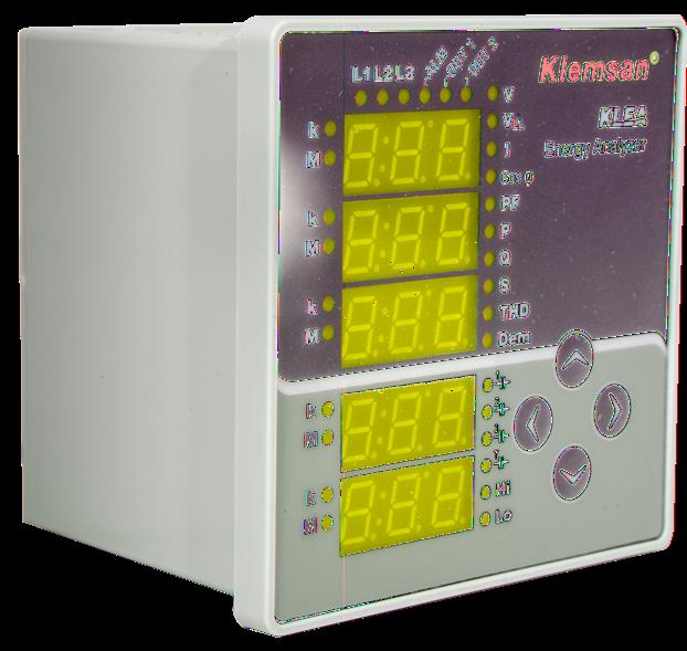
7 SECTION 1 GENERAL INFORMATION 1.3 Panel Definitions Ecras Definitions Front Panel Figure 1-1 Ecras Front Panel 1, 2, 3, 4, 5 Indicators (7 segment displays). 6, 7, 8 Phase on/off LEDs. (L1, L2, L3) 9 Alarm LED (ALM). Lights in case of an alarm. (available for Ecras 120 and Ecras 220) 10, 11 Relay LEDs (OUT 1, OUT 2). Lights when the relay is engaged. (available for Ecras 120 and Ecras 220) 12 VL-N LED (V ). Lights when displaying the phase to neutral currents. 13 VLL LED (VLL). Lights when displaying the phase to phase currents. 14 Current LED (I). Lights when displaying the currents for the phases. 15 CosØ LED (Cos Ø). Lights when displaying the cosø for the phases. 16 Power Factor LED (PF). Lights when displaying the PFs for the phases. 17 Active power LED (P). Lights when displaying the active powers for the phases. 18 Reactive power LED (Q). Lights when displaying the reactive powers for the phases. 19 Apparent power LED (S). Lights when displaying the apparent powers for the phases. 20 Total Harmonic Distortion LED (THD). Lights when displaying THDs for the phases. 21 Demand LED (Dem). Lights when displaying the demand values Phase QCap. LED ( 1 ).Lights when the load for the first phase is capacitive Phase QCap. LED ( 2 ). Lights when the load for the second phase is capacitive Phase QCap. LED ( 3 ). Lights when the load for the third phase is capacitive. 25 System QCap. LED ( T ). Lights when the total system load is capacitive. 26 Maximum LED (Hi). Lights when displaying the maximum values. 27 Minimum LED (Lo). Lights when displaying the minimum values. 28, 30,..,36 Mega LED (M). Lights when the indicated value is in MEGA units. 29, 31,..,37 Kilo LED (k). Lights when the indicated value is in KILO units. 38 Right arrow key. Use this key to switch between the menus, enter submenus and move through the indicator digits. 39 Up arrow key. Use this key to switch between the menus and change the numerical values. 40 Left arrow key. Use this key to switch between the menus, return to the upper menu level and confirm the selected value. 41 Down arrow key. Use this key to switch between the menus and change the numerical values. Back Panel l1-k1, l2-k2, l3-k3 : Current measurement inputs V1, V2, V3, N : Voltage measurement inputs D+, GND, D- : RS 485 (available for Ecras 200 and Ecras 220) out1, out2 : Alarm relay outputs (available for Ecras 120 and Ecras 220) Un : Power supply 7
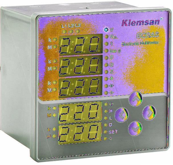
8 The menu structure of KLEA 110P and POWYS 3111 Energy Analyzer have same specifications. All descriptions are made for KLEA 220P.
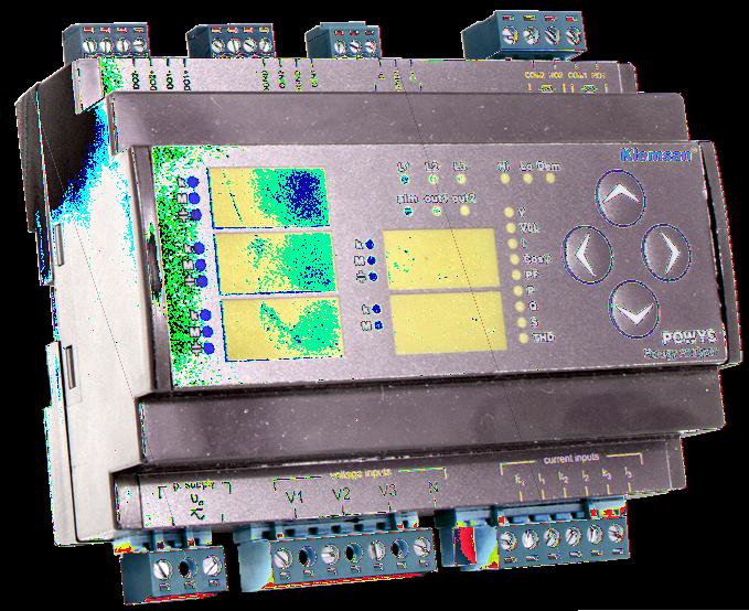
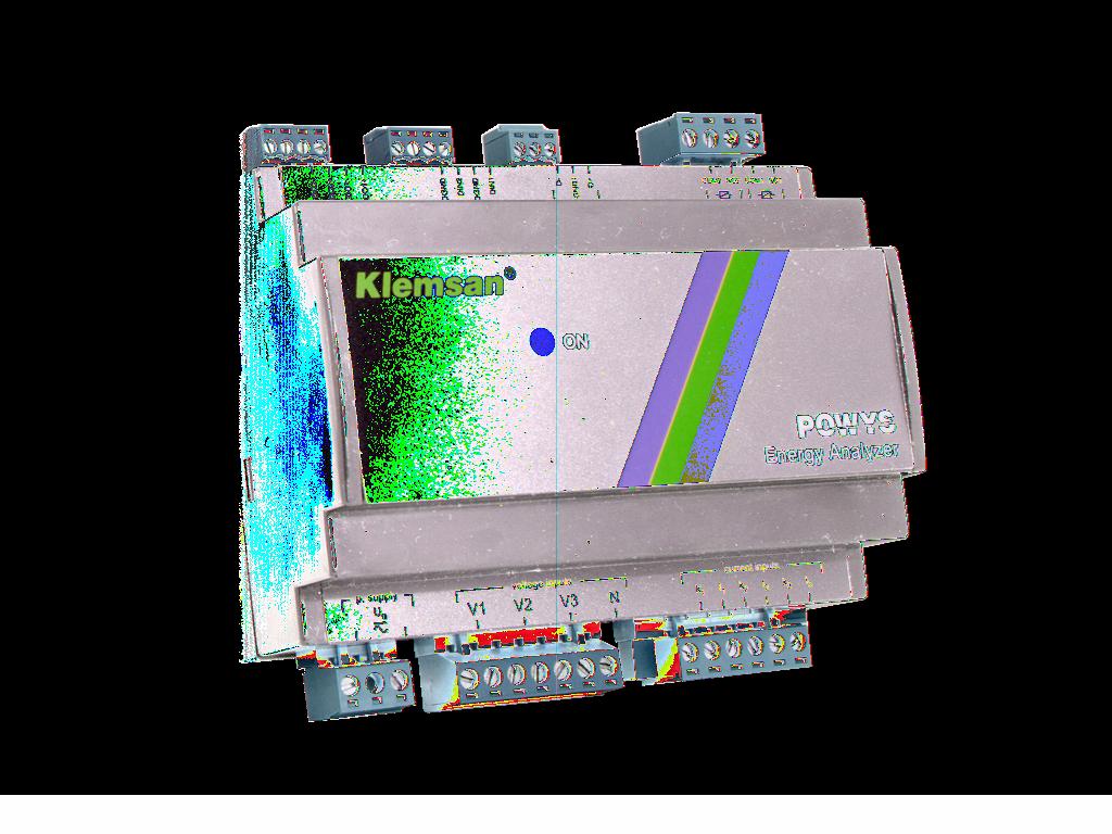
9 SECTION 1 GENERAL INFORMATION POWYS Definitions Figure 1-3 Powys Front Panel 1 Digital Outputs: Output1; DO1- and DO1+, Output2; DO2- and DO2+ (available for Powys 3101) 2 Digital Inputs. Input1:DIN1 and DGND, Input2:DIN2 and DGND (available for Powys 3101) 3 RS485 Communication 4 Relay Outputs: OUT 1 and OUT 2 (available for Powys 3101) 5 Power supply (Un) 6 Voltage Measurement Inputs (V1, V2, V3, N) 7 Current Measurement Inputs (I1-k1, I2-k2, I3-k3) 8 Power LED: It is turned on when the device is energized. 9
10 SECTION 1 GENERAL INFORMATION 1.4 Menu Structure Menus and moving through them are shown in the below table. Table 1-2 Menu Structure Instantaneous Values Maximum Values Minimum Values Demand Values Voltage (L- N) Voltage (L- N) Maximum Voltage (L- N) Minimum Voltage (L- L) Voltage (L- L) Maximum Voltage (L- L) Minimum Current Current Maximum Current Minimum Current Demand Cos φ Cos φ Maximum Cos φ Minimum Power Factor Power Factor Maximum Power Factor Minimum Active Power Active Power Maximum Active Power Minimum Active Power Demand Reactive Power Reactive Power Maximum Reactive Power Minimum Reactive Power Demand Apparent Power Apparent Power Maksimum Apparent Power Minimum Apparent Power Demand THDV THDV Maximum THDV Minimum THDI THDI Maximum THDI Minimum Energy Meters Counters Setting Upper menu structure will be changed according to version of KLEA 110P, POWYS and ECRAS. POWYS 3100 and POWYS 3101 has not display or LCD screen. So upper menu is not valid for POWYS 3100 and POWYS
11 SECTION 1 GENERAL INFORMATION 1.5 Four Quadrant Representation The angle(ø) between voltage and current provides us information about the direction of energy flow. A positive sign for active/reactive power indicates that active/reactive power is consumed. And also a negative sign for active/reactive power indicates that active/reactive power is generated. Reactive Power QUADRANT -2 P => negative Q => positive & capacitive CosØ => capacitive PF => negative Meters Exp. Active & Imp. Reactive QUADRANT -1 P => positive Q => positive & inductive CosØ => inductive PF => positive Meters Imp. Active & Imp. Reactive S Q P Active Power QUADRANT -3 P => negative Q => negative & inductive CosØ => inductive PF => negative Meters Exp. Active & Exp. Reactive QUADRANT -4 P => positive Q => negative & capacitive CosØ => capacitive PF => positive Meters Imp. Active & Exp. Reactive Figure 1-4 Four Quadrant Representation NOTE: If the signs of active and reactive power are examined, it can be defined the quadrant that Klea measures. In order to understand P and Q signs in Klea 110P and Ecras, instantaneous displays for P and Q must be checked. If active power display is seem constantly, it means active power(p) is positive. If it is blinked, it means active power(p) is negative. If reactive power(q) display is seem constantly, it means reactive power(q) is positive. If it is blinked, it means reactive power(q) is negative. NOTE: Signs of P and Q can be reached through modbus communication. e.g.; P= +10kW, Q= +5kVAr => Quadrant-1 P= -10kW, Q= +5kVAr => Quadrant-2 P= -10kW, Q= -5kVAr => Quadrant-3 P= +10kW, Q= -5kVAr => Quadrant-4 11
12 Energy Analyzer Rail Mounted Energy Analyzer Electronic Multimeter SECTION 2 INSTALLATION 12
13 SECTION 2 INSTALLATION SECTION 2 INSTALLATION 2.1 Preparing for Installation The purchased product may not include all hardware options referred in this document. This situation does not constitute an impediment to the electrical installation. Assembly and related connections of the product, must be implemented by authorized persons in accordance with the instructions of user manual. The device must not be put into service if the operator is not sure that all connections are correctly accomplished. 2.2 Mounting KLEA and Ecras are placed vertically into the gap located in the panel. After the product is placed into the panel, fixing brackets should be installed on the product. After that it should be fixed to the panel wall with the screws. Powys is replaced onto 35mm standart rail. Before wiring up voltage and current ends to KLEA, you must be sure that the power is cut. The product is connected to current transformer(s). Before disconnecting current transformer leads, be sure that they are short circuited elsewhere or connected to a parallel load which has sufficiently low impedance. Otherwise dangerously high voltages will be induced at the current transformer leads. Same phenomena also apply for putting into service. 13
14 SECTION 2 INSTALLATION 2.3 Connection Diagrams Star and Delta Connections Star Connection (with neutral) Delta Connection (no neutral) Measuring Current Measuring Voltage Measuring Current Measuring Voltage Figure 2-1 Connection Diagram For ECRAS, KLEA and POWYS 3111; L1, L2, L3 LEDs blink simultaneously and very slowly (per second) phase sequence (voltage) error. Any/All of L1, L2, L3 LED(s) blink(s) slowly (per 0.5 second) voltage connection(s) of the related phase(s) is/are missing. Any/All of L1, L2, L3 LED(s) blink(s) quickly (per 0.2 second) current connection(s) of the related phase(s) is/are missing Digital Output Connection Diagram DO (+) DO (-) External DC Power Supply must be connected. (5-30VDC) + - yük Figure 2-2 Digital Output Connection Diagram 14
15 SECTION 2 INSTALLATION 2.4 Dimensions (mm) Figure 2-3 Dimensions for Klea and Ecras Figure 2-4 Dimensions for Powys 15
16 Energy Analyzer Rail Mounted Energy Analyzer Electronic Multimeter SECTION 3 MENUS 16
17 SECTION 3 MENUS SECTION 3 MENUS 3.1 Instantaneous Measurement Menus NOTE: In order to reach Powys measurement, operator should use modbus communication. Voltage (L-N and L-L), current, neutral current, cosø, power factor, active power, reactive power, apparent power, THDV and THDI values are shown in instantaneous menu. See Table 3-1 for parameters displayed in the menus and activated LEDs. LED 1 LED 2 Active Menu 1st Indicator V - VLL - Voltage (Phase- Neutral) Voltage (Phase- Phase) Table 3-1 Instantaneous Measurements 2nd Indicator 3rd Indicator Voltage L1 Voltage L2 Voltage L3 Voltage L1-L2 Voltage L2-L3 Voltage L3-L1 4th Indicator Average Voltage (Phase-Neutral) Average Voltage (Phase- Phase) 5th Indicator Network Frequency Network Frequency I - Current Current L1 Current L2 Current L3 Total Current Network Current Cos φ - Cos φ Cos φ1 Cos φ2 Cos φ3 - - PF - Power Factor PF1 PF2 PF3 System PF - P - Active Power Q - Reactive Power S - Apparent Power Total Harmonic Distortion Active Power L1 Reactive Power L1 Apparent Power L1 Active Power L2 Reactive Power L2 Apparent Power L2 Active Power L3 Reactive Power L3 Apparent Power L3 Total Active Power Total Reactive Power Total Apparent Power THD V THDV1 THDV2 THDV3 - - I THDI1 THDI2 THDI Q / Cosφ Cosφ and reactive power for the L1 phase is capacitive, otherwise is inductive. 2 Q / Cosφ Cosφ and reactive power for the L2 phase is capacitive, otherwise is inductive. 3 Q / Cosφ Cosφ and reactive power for the L3 phase is capacitive, otherwise is inductive. T Q Total reactive power is capacitive, otherwise is inductive
18 SECTION 3 MENUS PF P Q S THD Dem T Hi Lo Figure 3-1 Voltage (Phase-Neutral) Display e.g: When V LED is turned on: l Device is in phase-neutral voltage menu. l Line-1 phase-neutral voltage is monitored in the first display. l Line-2 phase-neutral voltage is monitored in the second display. l Line-3 phase-neutral voltage is monitored in the third display. l Average phase-neutral voltage of three phase is monitored in fourth display. l Network frequency is monitored in fifth display For ECRAS KLEA and POWYS 3111; L1, L2, L3 LEDs blink simultaneously and very slowly (per second) phase sequence (voltage) error. Any/All of L1, L2, L3 LED(s) blink(s) slowly (per 0.5 second) voltage connection(s) of the related phase(s) is/are missing. Any/All of L1, L2, L3 LED(s) blink(s) quickly (per 0.2 second) current connection(s) of the related phase(s) is/are missing. When the product is mounted on a panel which consumes power, active power (P) must be positive. If active power (P1, P2 or P3) display is blinking in L-H and/or instantaneous menu, operator should cross connect k-l leads of the current transformer (999 MEGA) is the highest number that can be displayed in 7 segment displays of the product. If this number is exceeded; Related k, M LEDs will turn on (flash constantly). 888 number will be monitored in the related 7 segment display. This phenomenon applies for Instantaneous and L-H menus. 18
19 SECTION 3 MENUS 3.2 Maximum, Minimum ve Demand Menus Minimum and maximum values are calculated and stored in the non-volatile memory for below parameters. l Voltage (phase-neutral, phase-phase) l Neutral current l Frequency l CosØ l Power factor l THDV l THDI Besides maximum and minimum values, demand values are calculated and stored in the non-volatile memory for below parameters. l Current l Active power l Reactive power l Apparent power Use the left or right arrow keys to display the max. and min. measurements and demand values within the measurement menus. Table 3-1 shows the menu movements. Table 3-2 shows the indicated values and active LEDs in the corresponding menu. 19
20 SECTION 3 MENUS Table 3-2 Maximum, Minimum and Demand Values LED 1 LED 2 LED 3 1st Indicator 2nd Indicator 3rd Indicator 4th Indicator 5th Indicator V VLL I Cos φ PF P Q S THD Hi - Lo - Hi - Lo - Hi - Voltage L1 Max. Voltage L1 Min. Voltage L1-L2 Max. Voltage L1-L2 Min. Current L1 Max. Voltage L2 Max. Voltage L2 Min. Voltage L2-L3 Max. Voltage L2-L3 Min. Current L2 Max. Voltage L3 Max. Voltage L3 Min. Voltage L3-L1 Max. Voltage L3-L1 Min. Current L3 Max. Lo - Current L1 Min. Current L2 Min. Current L3 Min. Dem - Current L1 Demand Current L2 Demand Current L3 Demand Average Voltage Max. (Phase- Neutral) Average Voltage Min. (Phase- Neutral) Average Voltage Max. (Phase- Phase) Average Voltage Min. (Phase- Phase) Total Current Max. Total Current Min. Total Current Demand Network Frequency Max. Network Frequency Min. Network Frequency Max. Network Frequency Min. Neutral Current Max. Neutral Current Min. Hi - Cos φ1 Max. Cos φ2 Max. Cos φ2 Max. - - Lo - Cos φ1 Min. Cos φ2 Min. Cos φ2 Min. - - Hi - PF1 Max. PF2 Max. PF3 Max. System PF Max. - Lo - PF1 Min. PF2 Min. PF3 Min. System PF Min. - Hi - Lo - Dem - Hi - Lo - Dem - Hi - Lo - Dem - Active Power L1 Max. Active Power L1 Min. Active Power L1 Demand Reactive Power L1 Max. Reactive Power L1 Min. Reactive Power L1 Demand Apparent Power L1 Max. Apparent Power L1 Min. Apparent Power L1 Demand Active Power L2 Max. Active Power L2 Min. Active Power L2 Demand Reactive Power L2 Max. Reactive Power L2 Min. Reactive Power L2 Demand Apparent Power L2 Max. Apparent Power L2 Min. Apparent Power L2 Demand Active Power L3 Max. Active Power L3 Min. Active Power L3 Demand Reactive Power L3 Max. Reactive Power L3 Min. Reactive Power L3 Demand Apparent Power L3 Max. Apparent Power L3 Min. Apparent Power L3 Demand Total Active Power Max. Total Active Power Min. Total Active Power Demand Total Reactive Power Max. Total Reactive Power Min. Total Reactive Power Demand Total Apparent Power Max. Total Apparent Power Min. Total Apparent Power Demand Hi V THDV1 Max. THDV2 Max. THDV3 Max. - - Lo V THDV1 Min. THDV2 Min. THDV3 Min. - - Hi I THDI1 Max. THDI2 Max. THDI3 Max. - - Lo I THDI1 Min. THDI2 Min. THDI3 Min
21 SECTION 3 MENUS PF P Q S THD Dem T Hi Lo Figure 3-2 Minimum Voltage (Phase-Neutral) Display e.g. : When V LED and Lo LED are turned on together: l Line-1 minimum phase-neutral voltage is monitored in the first display. l Line-2 minimum phase-neutral voltage is monitored in the second display. l Line-3 minimum phase-neutral voltage is monitored in the third display. l Minimum average phase-neutral voltage of three phase is monitored in fourth display. l Minimum network frequency is monitored in fifth display Minimum, maximum and demand values are stored in permanent memory. Refer to CLr menu to clear these values. If current/voltage of any of the phases is not connected, maximum value of the related parameter will be 0 in maximum page of L-H Menu. in minimum page of L-H Menu; k LED and M LED belonging to current/voltage will turn on continuously. Operator will monitor the number 888 in the related 7 segment display. 21
22 SECTION 3 MENUS 3.3 Energy Meters Menu (Enr) The devices which have DIO option, have two tariff meters (Klea 110P, POWYS 3101). Rest of them have only one tariff meter (Ecras 100, Ecras 120, Ecras 200, Ecras 220, POWYS 3100). These tariffs are shown in Enr menu. Each tariff has import active, export active, import reactive and export reactive meters. l Import Active Energy Meter (I.Ac) l Export Active Energy Meter (E.Ac) l Import Reactive Energy Meter (I.rE) l Export Reactive Energy Meter (E.rE) To activate the tariff 2 counters, choose tariff 2 ( tr2 ) as the digital input type and activate the digital input. In order to activate digital input, DIN+ and DIN- must be short circuited. Otherwise, tariff 1 is activated. PF P Q S THD Dem T Hi Lo Figure 3-3 Import Active Energy Display Counters are displayed in the format xxx xxx.xxx kwh / kvarh (See Fig. 3-3). All counters are reset at kwh / kvarh and then start over from zero. Current transformer ratio (Ctr) and voltage transformer ratio (Vtr) are not incorporated in the energy calculations. 22
23 SECTION 3 MENUS Assigning Predefined Value for Energy Meters In any meter menu, press and hold the right key for at least 2 seconds and the respective menu title starts blinking. Using the right arrow key, move to the digit you want to change and enter the value using the up/down arrows. When you are done entering the value, confirm using the left arrow key. Move on to the storage procedure to store the changes you made. (See 3.6 Save Procedure) If password protection is enabled, press and hold the right key for at least 2 sec to display the password authentication page. Enter the password to proceed to the counter assignment. 3.4 Counters Menu (Cnt) The devices which have DIO option, have this menu. (Klea 110P, POWYS 3101). The Counters (Cnt) menu contains the following counters: Digital Input( di ) Counter: When a digital input is assigned to a counter, it counts the changes in the digital input. The menu is displayed only in device versions with digital inputs. On hour Counter: Counts and displays the total on time for the device in hours. Run hour Counter: If the digital input type was set to run hour enable, it counts the time elapsed during the digital input is in active position. This counter requires signal from 3-phase voltage and 3-phase current inputs to function without connecting to a digital input. The measured value is displayed in hours. Int Counter: Counts the power interruptions for the device. Counters are indicated in the format xxx xxx. All counters are reset at and then start over from zero. Only the di and run hour counters can be assigned values or reset. Use the procedure for assigning default values to assign values to counters. (See 3.6 Save Procedure) 3.5 Settings Menu (SEt) Klea and Ecras setings are made in the SEt menu. Table 3-3 shows the Set menu tree. The settings of Powys are made through modbus. The menu tree is based on the fully equipped variant model. Some of the menus may be missing in less equipped models. Please see Table1-1 for a comparison of models. 23
24 SECTION 3 MENUS Menu Set Sub Menu 1 bsc Alr Sub Menu 2 Sub Menu 3 Table 3-3 SEt Menu Tree Sub Menu 4 Settings Basic settings Ctr Current transformer rate Utr Voltage transformer rate Con U ULL I In cos PF F StA del HI LO hst t HI LO hst t HI LO hst t HI LO hst t HI LO hst t HI LO hst t HI LO hst t Connection type options 3P4W connection type 3P3W connection type Alarm setup Description Voltage (phase-neutral) alarm setup Voltage (phase-neutral) alarm high limit Voltage (phase-neutral) alarm low limit Voltage (phase-neutral) alarm hysteresis value Voltage (phase-neutral) alarm delay time Voltage (phase-phase) alarm setup Voltage (phase-phase) alarm high limit Voltage (phase-phase) alarm high low limit Voltage (phase-phase) alarm hysteresis value Voltage (phase-phase) alarm delay time Current alarm setup Current alarm high limit Current alarm low limit Current alarm hysteresis value Current alarm delay time Neutral current alarm setup Neutral current alarm high limit Neutral current alarm low limit Neutral current hysteresis value Neutral current alarm delay time Cos φ alarm setup Cos φ alarm high limit Cos φ alarm low limit Cos φ alarm hysteresis value Cos φ alarm delay time Power factor alarm setup Power factor alarm high limit Power factor alarm low limit Power factor alarm hysteresis value Power factor alarm delay time Frequency alarm setup Frequency alarm high limit Frequency alarm low limit Frequency alarm hysteresis value Frequency alarm delay time 24
25 SECTION 3 MENUS Menu Set Sub Menu 1 OUT det Pın 485 din Sub Menu 2 rl1 rl2 Act Sub Menu 3 OFF LO HI OFF LO HI Sub Menu 4 Relay output setup Relay 1 setup Relay 1 OFF Description Assign relay 1 to level low alarms Assign relay 1 to level high alarms Relay 2 setup Relay 2 OFF Assign relay 2 to level low alarms Assign relay 2 to level high alarms Demand time setup Password protection setup Enable/disable password protection Timeout for password protection. If you do press any P t keys after entering the password or do not change any settings via MODBUS, password protection is re-enabled after the time has elapsed. CHg Change password RS485 setup bau Baud rate options Id Slave ID setup Parity check setup Prt non Parity check off Eun Even parity Odd Odd parity Digital input setup Digital input 1 setup Digital input 1 options OFF Off typ tr2 Enable tariff 2 Cnt Enable counter In1 run. Enable Run Hour dly Digital input 1 detection delay time Digital input 1 detection edge Edg ris Detection in rising edge FAL Detection in falling edge (Only valid for counter) bot Detection in both edges (Only valid for counter) Digital input 2 setup Digital input 2 options In2 OFF Off typ tr2 Enable tariff 2 Cnt Enable counter run. Enable Run Hour 25
26 SECTION 3 MENUS Menu Sub Menu 1 Sub Menu 2 Sub Menu 3 Sub Menu 4 Description dly Digital input 2 detection delay time Digital input 2 detection edge din In2 Edg ris FAL Detection in rising edge Detection in falling edge (Only valid for counter) bot Detection in both edges (Only valid for counter) Pulse output setup Pulse output 1 setup Pulse output 1 parameter setup OFF Off IA1 Assign to tariff 1 import active energy counter EA1 Assign to tariff 1 export active energy counter Ir1 Assign to tariff 1 import reactive energy counter o1 out Er1 IA2 Assign to tariff 1 export reactive energy counter Assign to tariff 2 import active energy counter EA2 Assign to tariff 2 export active energy counter Ir2 Assign to tariff 2 import reactive energy counter Er2 Assign to tariff 2 export reactive energy counter Set di1 di2 Assign to digital input 1 counter Assign to digital input 2 counter dur Pulse duration of the pulse output 1 PuL rat Step range for pulse output 1 Pulse output 2 setup Pulse output 2 parameter setup OFF Off IA1 Assign to tariff 1 import active energy counter EA1 Assign to tariff 1 export active energy counter Ir1 Assign to tariff 1 import reactive energy counter o2 out Er1 IA2 Assign to tariff 1 export reactive energy counter Assign to tariff 2 import active energy counter EA2 Assign to tariff 2 export active energy counter Ir2 Assign to tariff 2 import reactive energy counter Er2 Assign to tariff 2 export reactive energy counter di1 Assign to digital input 1 counter di2 Assign to digital input 2 counter dur Pulse duration of the pulse output 2 rat Step range for pulse output 2 26
27 SECTION 3 MENUS Menu Set Sub Menu 1 CLr Sub Menu 2 OFF All Enr Cnt HI LO ded SEt ALr Sub Menu 3 Sub Menu 4 Clear menu Clear abort Description Reset the device to factory settings Clear the energy counters Clear the counters Clear the max. values Clear the min. values Clear the demand values Reset the setup to factory settings Reset the alarm setup to factory settings Uer Firmware version information Basic Settings Menu (bsc) This is the menu item where you make the current transformer ratio, voltage transformer ratio and connection type settings. Please see Table 3-3 for the menu tree and Section 5 for the factory default settings. The calculated currents are multiplied by the current transformer ratio (Ctr) and the calculated voltages are multiplied by the voltage transformer ratio (Utr) to be indicated on the displays and the modbus addresses. If sta (3-phase, 4-wire connection type) was specified for the network connection setup, the initial menu is Voltage (Phase-Neutral). This menu is displayed first when the device is energized. If del (3-phase, 3-wire connection type) was specified for the network connection setup, the initial menu is Voltage (Phase-Phase). This menu is displayed first when the device is energized Alarm Settings Menu (ALr) Use this menu item to set the alarm limits, hysteresis value and alarm delay time. Please see Table 3-3 for the menu tree and Section 5 for the factory default settings. Outside the alarm limits: k and M LEDs for the related parameter start flashing at the same time. The ALM LED lights after the alarm delay time elapses; and if a relay assignment was made, LEDs for the OUT1 and/or OUT2 light and related relays are energized. 27
28 SECTION 3 MENUS Alarm example: Figure 3-4 Alarm Example (Alarm delay was set to zero) l A low limit alarm occurs at point A. l Alarm disappears at point B. l A high limit alarm occurs at point C. l Alarm disappears at point D Alarm Relay Settings Menu (OUt) Use this menu item to set the conditions of the alarm relays. You can set both alarm relays to the following positions: OFF : Relay does not energize in an alarm condition. LO : Relay energizes when a low limit alarm occurs. HI : Relay energizes when a high limit alarm occurs. Related relay is de-energized when the alarm condition ends. Please see Table 3-3 for the menu tree and Section 5 for the factory default settings Demand Period Setting Menu (det) Use this menu item to setup the demand period. At the end of the specified period, demand values are calculated in a periodic cycle. Please see Table 3-3 for the menu tree and Section 5 for the factory default settings Password Settings Menu (Pın) Use this menu item to turn the password protection on/off, set a password activation time and change password settings editing options. Please see Table 3-3 for the menu tree and Section 5 for the factory default settings. 4 digit password protects the product setup and counter menus against unauthorized access and modifications. When activated, a password query screen is displayed if someone attempts to change the values. After a successful login, the device will not ask for a password until the password activation time has elapsed. You can set this value in the respective menu item. Please see Table 3-3 for the menu tree and Section 5 for the factory default settings. 28
29 SECTION 3 MENUS If you do not press any keys after entering the password or do not change the settings via MODBUS, password protection is re-enabled after the password activation time has elapsed RS485 Settings Menu (485) Use this menu item to set the baudrate, slave ID and parity control settings in RS485 communication. Please see Table 3-3 for the menu tree and Section 5 for the factory default settings Digital Input Settings Menu (DIn) Use this menu item to set the on/off position, type, delay time and detection edge for the digital input. Please see Table 3-3 for the menu tree and Section 5 for the factory default settings.. Digital input is based on dry contact detection principle. Never apply signal to inputs. Otherwise there is risk of damaging the device. Digital input modes: Option to enable tariff 2 (tr2): If you choose this option for the digital input type, tariff 2 energy counters will be enabled when the digital input is active (dry contact must be applied from related DIN+ and DIN-). Option to enable the counter (Cnt) : If you choose this option for the digital input type, the counter will count the changes in the position of the digital input depending on the chosen detection edge. o If you choose rising edge detection (ris) for the detection edge, the counter will increase by 1 on each activation of the dry contact that is connected to the digital input. o If you choose falling edge detection (FAL) for the detection edge, the counter will increase by 1 on each de-activation of the dry contact that is connected to the digital input. o If you choose both edges detection (bot) for the detection edge, the counter will increase by 1 on each activation and de-activaton of the dry contact that is connected to the digital input. Run Hour enable option (run.) : If you choose this option for the digital input type, the run hour counter start counting when the digital input is active.(dry contact must be applied from related DIN+ and DIN-). Detection delay time: The input is enabled or disabled based on the detection delay time which is set to account for contact spikes or noise in the digital input. Detection edge: Use this menu item to choose the position where the digital input is detected active or passive. This menu is available only for the digital input mode counter. Other options always use the rising edge detection. 29
30 SECTION 3 MENUS Pulse Output Settings Menu (PuL) Use this menu item to specify the on/off position, output parameter, pulse duration and step range settings for the pulse outputs. You can freely choose the settings for each pulse output independent of each other. Please see Table 3-3 for the menu tree and Section 5 for the factory default settings. The pulse output is activated with an increase in the predefined output parameter that is equal to each step range and deactivates after the predefined time. Output parameter setup (out): Use this menu item to set the parameter dependency of the output. The respective output is closed when you choose OFF. Pulse duration setup (dur): Use this menu item to specify the time the pulse is active. Pulse step range (rat): Use this menu to specify the smallest possible increase for the input parameter that will output a pulse Clear Menu (CLr) Use this menu to delete the stored values in the memory and restore the factory settings. Please see Table 3-3 for the menu tree and Section 5 for the factory default settings. The following options are available in the clear menu: OFF : Disables the clear process. All : Clears all values stored in the memory and restores them to the default factory settings. Enr : Resets all energy counters. Cnt : Resets all counters. HI : Clears the maximum values stored in the memory. LO : Clears the minimum values stored in the memory. ded : Clears the demand values stored in the memory. Set : Restores all settings to the factory settings. ALr : Restores the alarm settings to the factory settings. In order to prevent an accidental deletion, no / YES prompt is displayed if you choose any option other than OFF. To confirm the action: Press the right key to blink the no sign. Use the up/down keys to change the no to YES. Then, press the left key to confirm the action. To discard the action: Press the right key to blink the no sign. Then, press the left key to confirm the no option and exit the menu without making any deletions. 30
31 SECTION 3 MENUS The device restarts if you choose SEt, ALr or All and confirm the action. It will not restart if you choose other options. It will clear the values and returns back to the CLr menu. 3.6 Save Procedure Changing Value/Setting There are 2 different menus for changing the values: l Multiple choice menus: These menus contain predefined options. Press the right key to choose and blink the first variable of the menu. Press the up/down keys to choose and blink the desired option. Then press the left button to complete your choice. l Menus with numerical input values: In these menus, move through the digits to set the desired value. Press the right key to choose and blink the first digit of the variable from the left. Use the right key to move through the digits. Use the up/down keys to increase/decrease the value of the active digit. Set the desired values for variables by setting the individual digit values and press the left key to complete your action Saving Return to the SEt menu if you want to store the changes you made in the Setting menu. The storage procedure is activated in this menu. See Save Procedure. Device restarts if you store the changes. Press the left key until you see the SAU no display to confirm or discard the changes you made. To confirm the changes : Press the right key to blink the no sign. Use the up/down keys to change the no to YES. Then, press the left key to store the changes. To discard the changes: Press the right key to blink the no sign. Then exit the menu using the left key without saving your changes. 31
32 Energy Analyzer Rail Mounted Energy Analyzer Electronic Multimeter SECTION 4 RS485 COMMUNICATION 32
33 SECTION 4 RS485 COMMUNICATION SECTION 4 RS485 COMMUNICATION Ecras 200, Ecras 220, Powys 3100 and Powys 3101 models support RS485 communication. The device that is bought may not support all the modbus address. Please see Table 1-1 for a comparison of models and Table 3-3 for the menu tree. 4.1 Readable and Writable Data The following functions are supported: Function 03H: This function reads the readable addresses in the modbus table. Function 10H: This function writes to the writable addresses in the modbus table. Definitions: R / W : Can read and write the value in this address. RO : Can only read the value in this address. WO : Can only write to this address. float : 32 bit floating number. Related modbus table is given below: Table 4-1 Readable and Writable Data Address Parameter Type Read/Write Write Condition Phase-1 Basic Measurements 0 Phase 1 Voltage (L-N) float RO 2 Phase 1-2 Voltage (L-L) float RO 4 Phase 1 Current float RO 6 Phase 1 Cosφ float RO 8 Phase 1 Power Factor float RO 10 Phase 1 Active Power float RO 12 Phase 1 Reactive Power float RO 14 Phase 1 Apparent Power float RO 16 Phase 1 THDV float RO 18 Phase 1 THDI float RO Phase-2 Basic Measurements 20 Phase 2 Voltage (L-N) float RO 22 Phase 2-3 Voltage (L-L) float RO 24 Phase 2 Current float RO 26 Phase 2 Cosφ float RO 28 Phase 2 Power Factor float RO 30 Phase 2 Active Power float RO 32 Phase 2 Reactive Power float RO 34 Phase 2 Apparent Power float RO 36 Phase 2 THDV float RO 38 Phase 2 THDI float RO 33
34 SECTION 4 RS485 COMMUNICATION Address Parameter Type Read/Write Write Condition Phase-3 Basic Measurements 40 Phase 3 Voltage (L-N) float RO 42 Phase 3-1 Voltage (L-L) float RO 44 Phase 3 Current float RO 46 Phase 3 Cosφ float RO 48 Phase 3 Power Factor float RO 50 Phase 3 Active Power float RO 52 Phase 3 Reactive Power float RO 54 Phase 3 Apparent Power float RO 56 Phase 3 THDV float RO 58 Phase 3 THDI float RO Common Measurements (Phase-1, Phase-2, Phase-3) 60 Average Voltage (L-N) float RO 62 Average Voltage (L-L) float RO 64 Total Current float RO 66 System Power Factor float RO 68 Total Active Power float RO 70 Total Reactive Power float RO 72 Total Apparent Power float RO 74 System Frequency float RO 76 Neutral Current float RO Phase-1 Voltage Harmonic Measurements 78 Phase 1 Voltage Harmonics 1 float RO 80 Phase 1 Voltage Harmonics 3 float RO 82 Phase 1 Voltage Harmonics 5 float RO 84 Phase 1 Voltage Harmonics 7 float RO 86 Phase 1 Voltage Harmonics 9 float RO 88 Phase 1 Voltage Harmonics 11 float RO 90 Phase 1 Voltage Harmonics 13 float RO 92 Phase 1 Voltage Harmonics 15 float RO 94 Phase 1 Voltage Harmonics 17 float RO 96 Phase 1 Voltage Harmonics 19 float RO 98 Phase 1 Voltage Harmonics 21 float RO 100 Phase 1 Voltage Harmonics 23 float RO 102 Phase 1 Voltage Harmonics 25 float RO 104 Phase 1 Voltage Harmonics 27 float RO 106 Phase 1 Voltage Harmonics 29 float RO 108 Phase 1 Voltage Harmonics 31 float RO Phase-1 Current Harmonic Measurements 110 Phase 1 Current Harmonics 1 float RO 112 Phase 1 Current Harmonics 3 float RO 114 Phase 1 Current Harmonics 5 float RO 116 Phase 1 Current Harmonics 7 float RO 118 Phase 1 Current Harmonics 9 float RO 120 Phase 1 Current Harmonics 11 float RO 122 Phase 1 Current Harmonics 13 float RO 124 Phase 1 Current Harmonics 15 float RO 34
35 SECTION 4 RS485 COMMUNICATION Address Parameter Type Read/Write Write Condition 126 Phase 1 Current Harmonics 17 float RO 128 Phase 1 Current Harmonics 19 float RO 130 Phase 1 Current Harmonics 21 float RO 132 Phase 1 Current Harmonics 23 float RO 134 Phase 1 Current Harmonics 25 float RO 136 Phase 1 Current Harmonics 27 float RO 138 Phase 1 Current Harmonics 29 float RO 140 Phase 1 Current Harmonics 31 float RO Phase-2 Voltage Harmonic Measurements 142 Phase 2 Voltage Harmonics 1 float RO 144 Phase 2 Voltage Harmonics 3 float RO 146 Phase 2 Voltage Harmonics 5 float RO 148 Phase 2 Voltage Harmonics 7 float RO 150 Phase 2 Voltage Harmonics 9 float RO 152 Phase 2 Voltage Harmonics 11 float RO 154 Phase 2 Voltage Harmonics 13 float RO 156 Phase 2 Voltage Harmonics 15 float RO 158 Phase 2 Voltage Harmonics 17 float RO 160 Phase 2 Voltage Harmonics 19 float RO 162 Phase 2 Voltage Harmonics 21 float RO 164 Phase 2 Voltage Harmonics 23 float RO 166 Phase 2 Voltage Harmonics 25 float RO 168 Phase 2 Voltage Harmonics 27 float RO 170 Phase 2 Voltage Harmonics 29 float RO 172 Phase 2 Voltage Harmonics 31 float RO Phase-2 Current Harmonic Measurements 174 Phase 2 Current Harmonics 1 float RO 176 Phase 2 Current Harmonics 3 float RO 178 Phase 2 Current Harmonics 5 float RO 180 Phase 2 Current Harmonics 7 float RO 182 Phase 2 Current Harmonics 9 float RO 184 Phase 2 Current Harmonics 11 float RO 186 Phase 2 Current Harmonics 13 float RO 188 Phase 2 Current Harmonics 15 float RO 190 Phase 2 Current Harmonics 17 float RO 192 Phase 2 Current Harmonics 19 float RO 194 Phase 2 Current Harmonics 21 float RO 196 Phase 2 Current Harmonics 23 float RO 198 Phase 2 Current Harmonics 25 float RO 200 Phase 2 Current Harmonics 27 float RO 202 Phase 2 Current Harmonics 29 float RO 204 Phase 2 Current Harmonics 31 float RO Phase-3 Voltage Harmonic Measurements 206 Phase 3 Voltage Harmonics 1 float RO 208 Phase 3 Voltage Harmonics 3 float RO 210 Phase 3 Voltage Harmonics 5 float RO 35
36 SECTION 4 RS485 COMMUNICATION Address Parameter Type Read/Write Write Condition 212 Phase 3 Voltage Harmonics 7 float RO 214 Phase 3 Voltage Harmonics 9 float RO 216 Phase 3 Voltage Harmonics 11 float RO 218 Phase 3 Voltage Harmonics 13 float RO 220 Phase 3 Voltage Harmonics 15 float RO 222 Phase 3 Voltage Harmonics 17 float RO 224 Phase 3 Voltage Harmonics 19 float RO 226 Phase 3 Voltage Harmonics 21 float RO 228 Phase 3 Voltage Harmonics 23 float RO 230 Phase 3 Voltage Harmonics 25 float RO 232 Phase 3 Voltage Harmonics 27 float RO 234 Phase 3 Voltage Harmonics 29 float RO 236 Phase 3 Voltage Harmonics 31 float RO Phase-3 Current Harmonic Measurements 238 Phase 3 Current Harmonics 1 float RO 240 Phase 3 Current Harmonics 3 float RO 242 Phase 3 Current Harmonics 5 float RO 244 Phase 3 Current Harmonics 7 float RO 246 Phase 3 Current Harmonics 9 float RO 248 Phase 3 Current Harmonics 11 float RO 250 Phase 3 Current Harmonics 13 float RO 252 Phase 3 Current Harmonics 15 float RO 254 Phase 3 Current Harmonics 17 float RO 256 Phase 3 Current Harmonics 19 float RO 258 Phase 3 Current Harmonics 21 float RO 260 Phase 3 Current Harmonics 23 float RO 262 Phase 3 Current Harmonics 25 float RO 264 Phase 3 Current Harmonics 27 float RO 266 Phase 3 Current Harmonics 29 float RO 268 Phase 3 Current Harmonics 31 float RO Phase-1 Maximum Measurements 270 Phase 1 Max. Voltage (L-N) float RO 272 Phase 1-2 Max. Voltage (L-L) float RO 274 Phase 1 Max. Current float RO 276 Phase 1 Max. Cosφ float RO 278 Phase 1 Max. Power Factor float RO 280 Phase 1 Max. Active Power float RO 282 Phase 1 Max. Reactive Power float RO 284 Phase 1 Max. Apparent Power float RO 286 Phase 1 Max. THDV float RO 288 Phase 1 Max. THDI float RO Phase-2 Maximum Measurements 290 Phase 2 Max. Voltage (L-N) float RO 292 Phase 2-3 Max. Voltage (L-L) float RO 294 Phase 2 Max. Current float RO 36
37 SECTION 4 RS485 COMMUNICATION Address Parameter Type Read/Write Write Condition 296 Phase 2 Max. Cosφ float RO 298 Phase 2 Max. Power Factor float RO 300 Phase 2 Max. Active Power float RO 302 Phase 2 Max. Reactive Power float RO 304 Phase 2 Max. Apparent Power float RO 306 Phase 2 Max. THDV float RO 308 Phase 2 Max. THDI float RO Phase-3 Maximum Measurements 310 Phase 3 Max. Voltage (L-N) float RO 312 Phase 3-1 Max. Voltage (L-L) float RO 314 Phase 3 Max. Current float RO 316 Phase 3 Max. Cosφ float RO 318 Phase 3 Max. Power Factor float RO 320 Phase 3 Max. Active Power float RO 322 Phase 3 Max. Reactive Power float RO 324 Phase 3 Max. Apparent Power float RO 326 Phase 3 Max. THDV float RO 328 Phase 3 Max. THDI float RO Maximum Common Measurements (Phase-1, Phase-2, Phase-3) 330 Max. Average Voltage (L-N) float RO 332 Max. Average Voltage (L-L) float RO 334 Max. Total Current float RO 336 Max. System Power Factor float RO 338 Max. Total Active Power float RO 340 Max. Total Reactive Power float RO 342 Max. Total Apparent Power float RO 344 Max. System Frequency float RO 346 Max. Neutral Current float RO Phase-1 Minimum Measurements 348 Phase 1 Min. Voltage (L-N) float RO 350 Phase 1-2 Min. Voltage (L-L) float RO 352 Phase 1 Min. Current float RO 354 Phase 1 Min. Cosφ float RO 356 Phase 1 Min. Power Factor float RO 358 Phase 1 Min. Active Power float RO 360 Phase 1 Min. Reactive Power float RO 362 Phase 1 Min. Apparent Power float RO 364 Phase 1 Min. THDV float RO 366 Phase 1 Min. THDI float RO Phase-2 Minimum Measurements 368 Phase 2 Min. Voltage (L-N) float RO 370 Phase 2-3 Min. Voltage (L-L) float RO 372 Phase 2 Min. Current float RO 374 Phase 2 Min. Cosφ float RO 376 Phase 2 Min. Power Factor float RO 378 Phase 2 Min. Active Power float RO 380 Phase 2 Min. Reactive Power float RO 37
38 SECTION 4 RS485 COMMUNICATION Address Parameter Type Read/Write Write Condition 382 Phase 2 Min. Apparent Power float RO 384 Phase 2 Min. THDV float RO 386 Phase 2 Min. THDI float RO Phase-3 Minimum Measurements 388 Phase 3 Min. Voltage (L-N) float RO 390 Phase 3-1 Min. Voltage (L-L) float RO 392 Phase 3 Min. Current float RO 394 Phase 3 Min. Cosφ float RO 396 Phase 3 Min. Power Factor float RO 398 Phase 3 Min. Active Power float RO 400 Phase 3 Min. Reactive Power float RO 402 Phase 3 Min. Apparent Power float RO 404 Phase 3 Min. THDV float RO 406 Phase 3 Min. THDI float RO Minimum Common Measurements (Phase-1, Phase-2, Phase-3) 408 Min. Average Voltage (L-N) float RO 410 Min. Average Voltage (L-L) float RO 412 Min. Total Current float RO 414 Min. System Power Factor float RO 416 Min. Total Active Power float RO 418 Min. Total Reactive Power float RO 420 Min. Total Apparent Power float RO 422 Min. System Frequency float RO 424 Min. Neutral Current float RO Alarm Flags 426 Alarm Flags 32 bit integer RO Demand Measurements 428 Phase 1 Current Demand float RO 430 Phase 2 Current Demand float RO 432 Phase 3 Current Demand float RO 434 Total Current Demand float RO 436 Phase 1 Active Power Demand float RO 438 Phase 2 Active Power Demand float RO 440 Phase 3 Active Power Demand float RO 442 Total Active Power Demand float RO 444 Phase 1 Reactive Power Demand float RO 446 Phase 2 Reactive Power Demand float RO 448 Phase 3 Reactive Power Demand float RO 450 Total Reactive Power Demand float RO 452 Phase 1 Apparent Power Demand float RO 454 Phase 2 Apparent Power Demand float RO 456 Phase 3 Apparent Power Demand float RO 458 Total Apparent Power Demand float RO 38
39 SECTION 4 RS485 COMMUNICATION Address Parameter Type Read/Write Write Condition Digital Input 460 Digital Input 1 Counter 32 bit integer R / W If password protection is active, 462 Digital Input 2 Counter 32 bit integer R / W enter the password in the Settings Protection field and then enter 2222 in the Enable Counter 464 Run Hour Counter 32 bit integer R / W Change field. You can then enter the value. 466 On Hour Counter 32 bit integer RO 468 Power Interruptions Counter 32 bit integer RO Energy Meters Tariff 1 Total Energy Values (Phase1+Phase2+Phase3) 470 Import Active Energy T1 (Tariff 1) 32 bit integer R / W If password protection is active, 472 Export Active Energy T1 (Tariff 1) 32 bit integer R / W enter the password in the Settings Protection field and then enter 474 Import Reactive Energy T1 (Tariff 1) 32 bit integer R / W 2222 in the Enable Counter 476 Export Reactive Energy T1 (Tariff 1) 32 bit integer R / W Change field. You can then enter the value. Tariff 2 Total Energy Values (Phase1+Phase2+Phase3) 478 Import Active Energy T2 (Tariff 2) 32 bit integer R / W If password protection is active, 480 Export Active Energy T2 (Tariff 2) 32 bit integer R / W enter the password in the Settings Protection field and then enter 482 Import Reactive Energy T2 (Tariff 2) 32 bit integer R / W 2222 in the Enable Counter 484 Export Reactive Energy T2 (Tariff 2) 32 bit integer R / W Change field. You can then enter the value. Tariff 1 Phase1 Energy Values 486 Import Active Energy T1-Phase1 (Tariff 1) 32 bit integer R / W If password protection is active, 488 Export Active Energy T1-Phase1 (Tariff 1) 32 bit integer R / W enter the password in the Settings Protection field and then enter 490 Import Reactive Energy T1-Phase1 (Tariff 1) 32 bit integer R / W 2222 in the Enable Counter 492 Export Reactive Energy T1-Phase1 (Tariff 1) 32 bit integer R / W Change field. You can then enter the value. Tariff 1 Phase 2 Energy Values 494 Import Active Energy T1-Phase2 (Tariff 1) 32 bit integer R / W If password protection is active, 496 Export Active Energy T1-Phase2 (Tariff 1) 32 bit integer R / W enter the password in the Settings Protection field and then enter 498 Import Reactive Energy T1-Phase2 (Tariff 1) 32 bit integer R / W 2222 in the Enable Counter 500 Export Reactive Energy T1-Phase2 (Tariff 1) 32 bit integer R / W Change field. You can then enter the value. Tariff 1 Phase 3 Energy Values 502 Import Active Energy T1-Phase3 (Tariff 1) 32 bit integer R / W If password protection is active, 504 Export Active Energy T1-Phase3 (Tariff 1) 32 bit integer R / W enter the password in the Settings Protection field and then enter 506 Import Reactive Energy T1-Phase3 (Tariff 1) 32 bit integer R / W 2222 in the Enable Counter 508 Export Reactive Energy T1-Phase3 (Tariff 1) 32 bit integer R / W Change field. You can then enter the value. Tariff 2 Phase 1 Energy Values 510 Import Active Energy T2-Phase1 (Tariff 2) 32 bit integer R / W If password protection is active, 512 Export Active Energy T2-Phase1 (Tariff 2) 32 bit integer R / W enter the password in the Settings Protection field and then enter 514 Import Reactive Energy T2-Phase1 (Tariff 2) 32 bit integer R / W 2222 in the Enable Counter 516 Export Reactive Energy T2-Phase1 (Tariff 2) 32 bit integer R / W Change field. You can then enter the value. 39
40 SECTION 4 RS485 COMMUNICATION Address Parameter Type Read/Write Write Condition Tariff 2 Phase 2 Energy Values 518 Import Active Energy T2-Phase2 (Tariff 2) 32 bit integer R / W If password protection is active, 520 Export Active Energy T2-Phase2 (Tariff 2) 32 bit integer R / W enter the password in the Settings Protection field and then enter 522 Import Reactive Energy T2-Phase2 (Tariff 2) 32 bit integer R / W 2222 in the Enable Counter 524 Export Reactive Energy T2-Phase2 (Tariff 2) 32 bit integer R / W Change field. You can then enter the value. Tariff 2 Phase 3 Energy Values 526 Import Active Energy T2-Phase3 (Tariff 2) 32 bit integer R / W If password protection is active, 528 Export Active Energy T2-Phase3 (Tariff 2) 32 bit integer R / W enter the password in the Settings Protection field and then enter 530 Import Reactive Energy T2-Phase3 (Tariff 2) 32 bit integer R / W 2222 in the Enable Counter 532 Export Reactive Energy T2-Phase3 (Tariff 2) 32 bit integer R / W Change field. You can then enter the value. Device Settings 534 Current Transfer Rate (CTR) 32 bit integer R / W 536 Voltage Transfer Rate (VTR) float R / W 538 Connection Type 32 bit integer R / W 540 Relay 1 Function 32 bit integer R / W 542 Relay 2 Function 32 bit integer R / W 544 Demand Time 32 bit integer R / W 546 Password Enable 32 bit integer R / W 548 Password Activation Time 32 bit integer R / W 550 Password Value 32 bit integer R / W 552 Baud Rate 32 bit integer R / W 554 Slave ID 32 bit integer R / W 556 Parity Control 32 bit integer R / W 558 Digital Input 1 Type 32 bit integer R / W 560 Digital Input 1 Delay Time 32 bit integer R / W Enter the password in the Settings 562 Digital Input 1 Edge 32 bit integer R / W Protection field if password 564 Digital Input 2 Type 32 bit integer R / W protection is enabled. 566 Digital Input 2 Delay Time 32 bit integer R / W 568 Digital Input 2 Edge 32 bit integer R / W 570 Pulse Output 1 Parameter 32 bit integer R / W 572 Pulse Output 1 Duration 32 bit integer R / W 574 Pulse Output 1 Rate 32 bit integer R / W 576 Pulse Output 2 Parameter 32 bit integer R / W 578 Pulse Output 2 Duration 32 bit integer R / W 580 Pulse Output 2 Rate 32 bit integer R / W 582 Reserve 32 bit integer R / W 584 Reserve 32 bit integer R / W 586 Reserve 32 bit integer R / W 588 Reserve 32 bit integer R / W 590 Reserve 32 bit integer R / W 40
ENA33LCD. Power line analyzer. User and service manual. Obrezija 5 SI-1411 Izlake
 ENA33LCD Power line analyzer User and service manual version 2.9 (FW version 6.8 and newer) ETI, d.o.o. Obrezija 5 SI-1411 Izlake www.etigroup.eu/products-services 1. Front control panel and terminal plate
PLA 33. Power line analyzer. User and service manual. version 2.4
 PLA 33 Power line analyzer User and service manual version 2.4 Content. Front control panel and terminal plate...3 7.2.2. System frequency setting...0 2. Device description...4 7.2.3. Password protection...0
FCR 06, FCR 12. Power factor correction controller. User and service manual
 FCR 06, FCR 12 Power factor correction controller User and service manual version 2.3 Czech Republic Czech Republic 1 Content 1. Control and signal elements... 3 2. Device description... 4 3. Instruction
Contents. Introduction and description Package contents Device identification PM Options... 80
 Contents 1 Introduction and description Package contents... 77 Device identification... 77 2 Characteristics PM500... 78 Options... 80 3 Installation Front-panel cut-out... 82 Mounting... 82 4 Connections
Ziegler EM 1320/30/40
 Ziegler EM 1320/30/40 Operating Manual Ziegler EM 1340 2-60-006-00-00483_Rev. C - 9/2014 www.ziegler-instruments.com 1 36 DIGITAL MULTIFUNCTION INSTRUMENT Programmable Multi-function Energy Meter Installation
Installation Instructions and Reference Handbook. Installation instructions
 Installation Instructions and Reference Handbook Multi-instrument MIB 7000/7000C/7020 4189320016B (UK) DEIF A/S Product information Installation instructions Basic operation DEIF A/S, Frisenborgvej 33
EASTRON SDM630MCT-RJV / SDM630MCT-RJA User Manual V1.1. Three phase multifunction din rail energy meter
 SDM630MCT-RJV-333mV SDM630MCT-RJA-00mA Three phase multifunction din rail energy meter Plug-in solution; labor saving; wiring mistake free Measures kwh KVarh, KW, Kvar, KVA, P, F, PF, Hz, dmd, V, A, THD,etc.
SUPPLY NETWORK ANALYZER CVM-96 SERIES
 SUPPLY NETWORK ANALYZER CVM-96 SERIES (Power Demand) INSTRUCTION MANUAL ( M 981 326 / 00B - GB) (c) CIRCUTOR S.A. ----- Supply network analyzer CVM-96 ------ User's manual --- Page No. 1 CVM-96 SUPPLY
RISH Master 3440i/3440iDL 0.2S
 Operating Manual RISH Master 3440i/3440iDL 0.2S as per IEC62053-22 Touch Screen Digital Multi-Function Meter Installation & Operating Instructions Section Contents 1. Introduction INDEX 2. Measurement
Installation and Operating Instructions
 Energy Division Installation and Operating Instructions Quadratic Integra 1530 Digital Metering Systems Our commitment. Your advantage. Contents Page 1 Introduction 4 1.1 Measurement Capabilities 5 1.2
Operating Manual RISH EM 1320/30/ _Rev. C - 9/2014
 Operating Manual RISH EM 1320/30/40 1 2-60-006-00-00483_Rev. C - 9/2014 2 DIGITAL MULTIFUNCTION INSTRUMENT Programmable Multi-function Energy Meter Installation & Operating Instructions Section Contents
Centrale de mesure Power Meter PM500 Merlin Gerin
 Notice d'installation et d'utilisation Installation and user manual Centrale de mesure Power Meter PM500 Merlin Gerin 059473_D Introduction and description Package contents c one PM500 power meter with
DMTME-96 2CSG133030R4022 M DMTME-I Operation and assembly instructions 2CSG163030R4022 M CSG445001D0202
 DMTME-96 2CSG133030R4022 M204675 DMTME-I-485-96 2CSG163030R4022 M204685 2CSG445001D0202 GB Operation and assembly instructions DMTME-96: three-phase multimeter for panel mounting, used also in singlephase
Data Sheet. RISH Master Record %THD
 Data Sheet %THD Application : measures important electrical parameters & replaces the multiple analog panel meters. It measures electrical parameters like AC current, Voltage, frequency, active energy
PM-PA/PM-PAC POWER ANALYZER
 PM-PA/PM-PAC POWER ANALYZER 1. INTRODUCTION Power Analyzer is an ideal device to control measure and monitor all electrical parameters of a system. Thanks to its four display rows, all parameters can be
INTELLIGENT DIGITAL MULTI POWER METER [DIC-MPM]
![INTELLIGENT DIGITAL MULTI POWER METER [DIC-MPM]](/thumbs/89/100574794.jpg "INTELLIGENT DIGITAL MULTI POWER METER [DIC-MPM]") Feature Suit for LV/ HV voltage system Compact design with all real-time measurement Consist of basic unit and optional modules 10 years back-up of integrated energy data Large LCD, high brightness High
Feature Suit for LV/ HV voltage system Compact design with all real-time measurement Consist of basic unit and optional modules 10 years back-up of integrated energy data Large LCD, high brightness High
Installation and Operating Instructions Quadratic Integra 1530 Digital Metering Systems
 Installation and Operating Instructions Quadratic Integra 1530 Digital Metering Systems Tyco Electronics UK Limited Crompton Instruments Freebournes Road, Witham, Essex, CM8 3AH, UK Tel: +44 1376 509 509
RI-F200 Series. Single and Three Phase Multifunction Energy Meter. Telephone : +44 (0) Displayed Parameters
 Displayed Parameters") RI-F200 Series Single and Three Phase Multifunction Energy Meter DIN 96 panel mounted -/1A or -/5A current transformer input Single phase or three phase network compatible Programmable voltage and current
RI-F200 Series Single and Three Phase Multifunction Energy Meter DIN 96 panel mounted -/1A or -/5A current transformer input Single phase or three phase network compatible Programmable voltage and current
Energy Management Energy Meter Type EM340
 Energy Management Energy Meter Type EM340 Digital input (for tariff management Easy connection or wrong current direction detection Certified according to MID Directive (option PF only: see how to order
ALPHA 50 MULTIFUNCTION METER (ALPHA SERIES)
") Alpha Series www.sifamtinsley.co.uk Multifunction Meters Transducers & Isolators Temperature Controllers Converters & Recorders Digital Panel Meters Current Transformers Analogue Panel Meters Shunts ALPHA
Alpha Series www.sifamtinsley.co.uk Multifunction Meters Transducers & Isolators Temperature Controllers Converters & Recorders Digital Panel Meters Current Transformers Analogue Panel Meters Shunts ALPHA
UNIVERSAL MEASURING INSTRUMENTS. TNM 34xx. TNM 3410 / 3420 / 3430 / 3440 Universal measuring instrument 1/49
 TNM 3410 / 3420 / 3430 / 3440 Universal measuring instrument True RMS measurement User-friendly programing Four different types for optimal specification RS485 interface For 3- or 4-wire connection Compact
ZHUHAI PILOT TECHNOLOGY CO., LTD.
 SPM32 Multifunctional Power Meter SPM32 Multifunction Power Meter Installation & Operation Manual V1.0 ZHUHAI PILOT TECHNOLOGY CO., LTD. Danger and warning! This device can be installed only by professionals.
Multifunction network analyzer Q15U Q96U2L - Q96U4... Q15E Q96E MCU - MCUH Programmable transducer MCUU
 Multifunction network analyzer Q15U2... - Q96U2L - Q96U4... Q15E2... - Q96E2... - MCU - MCUH Programmable transducer MCUU OPERATING MANUAL Ipm0163.8 - Edition 06.09 Langer Messtechnik GmbH Soyerhofstrasse
PMAC770 Multifunction Power Meter. Installation & Operation Manual V2.0 ZHUHAI PILOT TECHNOLOGY CO., LTD.
 PMAC770 Multifunction Power Meter Installation & Operation Manual V2.0 ZHUHAI PILOT TECHNOLOGY CO., LTD. Danger and warning! This device can be installed only by professionals. The manufacturer shall not
Energy Management Energy Analyzer Type EM112
 Energy Management Energy Analyzer Type EM112 Single phase energy analyzer Class 1 (kwh according to EN62053-21 Class B (kwh according to EN50470-3 Accuracy ±0.5% RDG (current/voltage Direct current measurement
SUPPLY NETWORK ANALYZER
 SUPPLY NETWORK ANALYZER CVM-144 SERIES (Ethernet) (Ver 6.11 and higher) INSTRUCTION MANUAL (M98203401-03-06A) CIRCUTOR S.A. ----- Supply network analyzer CVM-144 ------ User's manual --- Page No. 1 CONTENTS
KLEA 220P ENERGY ANALYZER
 KLEA 220P ENERGY ANALYZER Defining KLEA 220P Energy Analyzer in simple terms KLEA 220P Energy Analyzer is an automation device which offers 3-phase energy monitoring, analyzing and controlling the network
SUPPLY NETWORK ANALYZER
 SUPPLY NETWORK ANALYZER CVM-144 SERIES (PROFIBUS-DP) INSTRUCTION MANUAL ( M 981 704 / 01A - GB) CIRCUTOR S.A. ----- Supply network analyzer CVM-144 (PROFIBUS) ------ --- Page No. 1 CONTENTS page 1.- DELIVERY
INSTRUCTION MANUAL. Power Factor Controller - 12 steps Model A12 NOKIAN CAPACITORS. Power Factor Controller A12
 INSTRUCTION MANUAL Power Factor Controller - 12 steps Model A12 NOKIAN CAPACITORS Power Factor Controller A12 1. CONTENTS 1. CONTENTS 1 2. FEATURES 2 3. INSTALLATION, CONNECTION AND APPLYING POWER 2 4.
Mounting Instructions / Manual MV1171
 Mounting Instructions / Manual MV1171 POWER FACTOR Controller ESTAmat MH-N Vishay Electronic GmbH ESTA Capacitors Division Revision: 19-April-2011 Hofmark-Aich-Strasse 36 84030 Landshut, Germany Phone
Energy Management Energy Analyzer Type EM111
 Energy Management Energy Analyzer Type EM111 Single phase energy analyzer Class 1 (kwh according to EN62053-21 Class B (kwh according to EN50470-3 Accuracy ±0.5% RDG (current/voltage Direct current measurement
Commissioning Instructions Rev. 03
 Power Factor regulator BLR-CM-T/RT L1 L2 L3 Einspeisung Supply Last Load BLR-CM-T + - Triggereingang/ Triggerinput BEL-TSXX N PE L1 L2 L3 Einspeisung Supply Last Load BLR-CM-RT + - Triggereingang/ Triggerinput
Digital Multifunction Instrument - Rish Master 3440
 Application Rish Master 3440 measures important electrical parameters in 3 phase and single phase etwork & replaces the multiple analog panel meters. It measures electrical parameters like AC current,
Technical Data Sheet
 Technical Data Sheet parameters in 3 phase 4 Wire and 3 phase 3 Wire Network & replaces the multiple analog panel meters. Special Features Pulse/Limit Switch output (optional) Number of interruption Application
ENCORE 300 SERIES INSTALLATION AND OPERATING INSTRUCTIONS
 ENCORE 300 SERIES INSTALLATION AND OPERATING INSTRUCTIONS Copyright 2002-2006 PRI Ltd. 9600-3004-2 Issue C Information contained within this document is subject to change without notice and does not represent
RISH PQM. Power Quality Monitor. Preliminary Datasheet subject to change without notice. Individual Harmonics measurement upto 56th Harmonics
 Power Quality Monitor Individual Harmonics measurement upto 56th Harmonics True representation of Voltage & Current waveforms. Phasor Representation of All 3 phases for system analysis Real Time Clock
POWER ANALYZER CVM-MINI SERIES INSTRUCTION MANUAL M A CIRCUTOR, SA
 POWER ANALYZER CVM-MINI SERIES INSTRUCTION MANUAL M98174001-03-15A CIRCUTOR, SA CONTENTS 1 BASIC INSTRUCTIONS... 3 1.1 Checks on receipt.... 3 1.2 Main features... 3 1.3 Electrical parameters... 3 1.4
Energy Management Energy Meter Type EM112
 Energy Management Energy Meter Type EM112 Easy connection or wrong current direction detection Other versions available (not certified, option X: see how to order on the next page Single phase energy meter
Energy Management Energy Meter Type EM111
 Energy Management Energy Meter Type EM111 Easy connection or wrong current direction detection Other versions available (not certified, option X: see how to order on the next page Single phase energy meter
THREE-PHASE ENERGY METER DIRECT CONNECTION PM30D01KNX. User manual
 THREE-PHASE ENERGY METER DIRECT CONNECTION PM30D01KNX User manual Product: PM30D01KNX Description THREE-PHASE ENERGY METER - DIRECT CONNECTION Document Version: 1.2 Date: 26 October 2017 15:14:00 1/8 INDEX
Monitoring Electric Network Via Internet
 Monitoring Electric Network Via Internet NETWORK ANALYSER let "it" analyse! MPR63 Real time monitoring via internet / intranet Measurement of all electrical parameters Including Harmonics Automatic recording
Integra 1560 and 1580 Digital Transducer Systems
 Integra 1560 and 1580 multi function transducers provide high accuracy
H8238/MCM MODBUS POINT MAP
 H8238/MCM MODBUS POINT MAP F O R M A T Int Float R/W NV Description 1 257/258 R/W NV Energy Consumption, kwh, Low-word integer 2 259/260 R/W NV Energy Consumption, kwh, High-word integer Both 257/258 and
53U MULTI POWER MONITOR OPERATING MANUAL MODEL 53U CONTENTS. (4 digital displays)
") OPERATING MANUAL MULTI POWER MONITOR (4 digital displays) MODEL 53U 53U CONTENTS BEFORE USE... 2 POINTS OF CAUTION... 2 LIGHTNING SURGE PROTECTION... 2 COMPONENT IDENTIFICATION... 3 INSTALLATION... 4 TERMINAL
OPERATING MANUAL MULTI POWER MONITOR (4 digital displays) MODEL 53U 53U CONTENTS BEFORE USE... 2 POINTS OF CAUTION... 2 LIGHTNING SURGE PROTECTION... 2 COMPONENT IDENTIFICATION... 3 INSTALLATION... 4 TERMINAL
PM-311x Quick Start Ver PM-311x introduction 1.1. Caution & Warning 1.2. Product Warranty & Customer Support
 PM-311x Quick Start Ver. 1.1 1. PM-311x introduction ICP DAS brings the most powerful, cost-effective, advanced Smart Power Meters PM-3000 series that gives you access to real-time electric usage for single-phase
RISH Master Digital Multifunction Instrument with onsite pluggable output options. Application : Product Features:
 Application : RISH Master 3430 measures important electrical parameters in 3 phase and single phase Network & replaces the multiple analog panel meters. It measures electrical parameters like AC current,
Operating Guide October 2006
 Operating Guide October 2006 Safety 1 Safety This manual represents your meter as manufactured at the time of publication. It assumes standard software. Special versions of software may be fitted, in which
PRELIMINARY DATA SHEET RI-D140. Three Phase Multifunction DIN Rail Energy Meter (MID Certified) MID
 MID") RI-D140 Three Phase Multifunction DIN Rail Energy Meter (MID Certified) Four module DIN rail mounted Energy pulse LED True RMS measurement Cost effective and accurate Modbus communication -/1A or -/5A
RI-D140 Three Phase Multifunction DIN Rail Energy Meter (MID Certified) Four module DIN rail mounted Energy pulse LED True RMS measurement Cost effective and accurate Modbus communication -/1A or -/5A
RI-D440. Three Phase easywire Multifunction DIN Rail Energy Meter. Telephone : +44 (0) Displayed Parameters
 Displayed Parameters") RI-D440 Three Phase easywire Multifunction DIN Rail Energy Meter Four module DIN rail mounted Energy pulse LED 330mV Input from easywire CTs (or -/1A and -/5A current transformer input with TAS-SCTEWA
RI-D440 Three Phase easywire Multifunction DIN Rail Energy Meter Four module DIN rail mounted Energy pulse LED 330mV Input from easywire CTs (or -/1A and -/5A current transformer input with TAS-SCTEWA
See notes for calculations 4110 Usage Hours 1 Integer RO Y - Hours YP Usage Minutes 1 Integer RO Y - Minutes 0-59 YP
 Table of Contents 2 FW Release summary Y Y Y Y Y Y PM RS FW History Y Y Y PM_2 OS FW History Y Y Y PM_2 RS FW History Y Y Y Setup & Status Metering Min Max Demand IO Alarms N N Reset Commands DL System
CVM-C5-ITF-485 CVM-C5-MC-485
 Power analyzer CVM-C5-ITF-485 CVM-C5-MC-485 CVM-C5-mV-485 INSTRUCTION MANUAL (M026B01-03-18A) 2 SAFETY PRECAUTIONS Follow the warnings described in this manual with the symbols shown below DANGER Warns
Technical Data Sheet AMIK 300 / 301
 USA SINCE 1936 RELIABILITY BEYOND MEASURE Technical Data Sheet AMIK 300 / 301 LISTED File No. E471457 AMIK AMIK 300 is a compact multifunction instrument with touch screen LCD utility which measures important
Energy Management. Type WM14 DIN Advanced version. Product Description 3-phase advanced power analyzer with integrated programming
 Energy Management Type WM14 DI version Protection degree (front): IP40 2 digital outputs 16 freely configurable alarms with OR/AD logic linkable with up to 2 digital outputs RS422/485 serial output (MODBUS-RTU),
Application Alpha 20 Measures important electrical parameters in 3 phase 4 Wire and 3 phase 3 Wire Network & replaces the multiple analog panel meters
 Technical Data Sheet Alpha 20 Alpha 20 is a compact multifunction instrument which Measures important electrical parameters in 3 phase 4 Wire and 3 phase 3 Wire Network & replaces the multiple analog panel
COUNTIS E23. Three-phase energy meter Direct - 80 A MODBUS. Instruction manual. en/countis-e2x
 Instruction manual COUNTIS E23/E24 Three-phase energy meter Direct - 80 A MODBUS COUNTIS E23 COUNTIS E24 - MID www.socomec.com/ en/countis-e2x Contents 1. Documentation.... 3 2. Hazards and warnings...
SUPPLY NETWORK ANALYZER. CVMk SERIES. CVMk-4C SERIES INSTRUCTION MANUAL. ( M / 00 B - Manual 1 / 2 ) (c) CIRCUTOR S.A.
 (c) CIRCUTOR S.A.") SUPPLY NETWORK ANALYZER CVMk SERIES & CVMk-4C SERIES INSTRUCTION MANUAL ( M 981 171 / 00 B - Manual 1 / 2 ) (c) CIRCUTOR S.A. ----- Supply network analyzer CVMk and CVMk-ITF ------ Manual 1 / 2 --- Page
SUPPLY NETWORK ANALYZER CVMk SERIES & CVMk-4C SERIES INSTRUCTION MANUAL ( M 981 171 / 00 B - Manual 1 / 2 ) (c) CIRCUTOR S.A. ----- Supply network analyzer CVMk and CVMk-ITF ------ Manual 1 / 2 --- Page
Modbus communication module for TCX2: AEX-MOD
 Modbus communication module for TCX2: Communication Specification TCX2 is factory installed in TCX2 series controllers with -MOD suffix, and is also available separately upon request for customer installation
COUNTIS E27/E28 Three-phase energy meter Direct - 80 A Ethernet
 INSTRUCTION MANUAL COUNTIS E27/E28 Three-phase energy meter Direct - 80 A Ethernet EN countis e27 countis e28 - mid www.socomec.com/ en/countis-e2x EN Contents 1. Documentation.... 3 2. Hazards and warnings...
Power Factor Controller RVT Installation and Operating Instructions
 Power Factor Controller RVT Installation and Operating Instructions Table of contents Read this first... 4 1 Introduction to the controller... 5 1.1 A powerful fully three phase individual controlled power
ENGLISH 3 Phase Multi-function Power Meter 1/5A MID MID
 Professionally approved products. Datasheet Stock Number: 144-0527 3 Phase Multi-function Power Meter 1/5A MID 96mm² Panel Mounted Power Meter. MID UK Specifications The 144-0527 is a new generation modern
PEM353. Universal measuring device
 353 Universal measuring device 353_D00335_00_D_XXEN/06.2018 353 Universal measuring device Product description The digital universal measuring device 353 is used to record and display measured quantities
Operating Manual. Digital Multifunctional Power Meter with LCD Display and Optional Modules WPM 770. Contents
 Operating Manual 679.B.141.02 Digital Multifunctional Power Meter with LCD Display and Optional Modules WPM 770 Contents 1. Safety Notes...3 2. General Information...4 3. Dimensions...5 4. Installation
RISH EM 3490 SS Kilowatt Hour Energy Meter With Rs485 RISH EM 3490 SS. Application : Product Features: Indication: Pulse Indication:
 Application : RISH Master 3490 SS is a 96mm x 96mm panel mounted kilowatt hour meter it measures active energy with class 1.0 accuracy having auto-resetting 8 digit seven segment LED counter. The unit
RAIL MOUNTED NETWORK METER TYPE N27P USER S MANUAL
 RAIL MOUNTED NETWORK METER TYPE N27P USER S MANUAL 1 2 Contents 1. APPLICATION... 5 2. METER SET... 6 3. BASIC REQUIREMENTS, SAFETY OF USE... 7 4. INSTALLATION... 8 4.1 Mounting method... 8 4.2 Connections...
VIP Current & Power Multimeter
 VIP Current & Power Multimeter Rev 1.6 Table of Contents 1. Mechanical Installation... 3 2. Wiring diagram... 4 3. Specifications... 5 Technical Specifications... 5 3.2 Measuring Specifications... 5 4.
ALPHA 20 MULTIFUNCTION METER (ALPHA SERIES)
") Alpha Series www.sifamtinsley.co.uk Multifunction Meters Transducers & Isolators Temperature Controllers Converters & Recorders Digital Panel Meters Current Transformers Analogue Panel Meters Shunts ALPHA
Alpha Series www.sifamtinsley.co.uk Multifunction Meters Transducers & Isolators Temperature Controllers Converters & Recorders Digital Panel Meters Current Transformers Analogue Panel Meters Shunts ALPHA
MODBUS RS485 SERIAL PROTOCOL
 MODBUS RS485 SERIAL PROTOCOL ED39DIN DMM3 VIP39DIN VIP396 SIRIO STAR3 STAR3din VERSION 09 JULY 2004 Modbus SIRIO.doc 09 JULY 2004 Pag.1/22 The STAR3, STAR3 din, VIP396, VIP39din, DMM3, SIRIO and ED39din
SMART 96 Piú USER'S MANUAL
 SMART 96 Piú USER'S MANUAL 01/2003 Table of Contents 1. INTRODUCTION... 1 2. SYSTEM ARCHITECTURE... 3 2.1 The RS485 Serial interface: network with up to 31 analysers... 4 2.2 The RS485 Serial interface:
Technical Data Sheet. x1000. kwh R Y B
 Technical Data Sheet x1000 Von kwh IRev 3600 imp /kwh R Y B is a compact multifunction instrument which is a 96mm x 96mm panel mounted kilowatt hour meter it measures active energy with class 1.0 accuracy
BU: EPBP GPG: DIN Rail Products Devices for the permanent control of insulation on supply lines for medical locations ISOLTESTER-DIG-RZ/RS/PLUS
 INSTRUCTION MANUAL BU: EPBP GPG: DIN Rail Products Devices for the permanent control of insulation on supply lines for medical locations ISOLTESTER-DIG-RZ/RS/PLUS 1/23 More information than that reported
Energy Division
 Energy Division http://energy.tycoelectronics.com Installation and Operating Manual Integra 1560 and 1580 Digital Metering and Transducer Systems Tyco Electronics UK Limited Crompton Instruments Freebournes
Energy Management Modular Power Analyzers Type WM2-96
 ISE, Inc. - 10100 Royalton Rd. - Cleveland, OH 44133 USA Energy Management Modular Power Analyzers Type WM2-96 - Tel: (440) 237-3200 - Fax: (440) 237-1744 - http://instserv.com Class 1 Modular power analyzer
Multi-functional Power Meter DPM-C530A User Manual.
 Multi-functional Power Meter DPM-C530A User Manual www.deltaww.com Table of Contents 1. Preface 2 2. Notes 3 2.1 Safety Notes 3 2.2 Installation Environment 4 3. Descriptions of Parts 5 3.1 Operating Interface
MID. Energy Management Energy Analyzer Type EM11 DIN. Product Description. How to order EM11 DIN AV8 1 X O1 PF. Type Selection EM11 DIN
 Energy Management Energy Analyzer Type EM11 DIN Other versions available (not certified, option X): see how to order on the next page Product Description Class 1 (kwh) according to EN62053-21 Class B (kwh)
Index CARLO GAVAZZI WM3-96
 2 Index CARLO GAVAZZI WM3-96 32bit µ-processor based power quality analyser with modular housing for Plug and Play modules FW rev. 12 Instruction manual: INDEX TO BEGIN WITH... 5 The main programming parameters...
MICROPROCESSOR-BASED METERING EQUIPMENT SECTION 16901C PART 2
 PART 1 PART 2 PRODUCTS 2.01 MANUFACTURERS A. Eaton products B.. C.. The listing of specific manufacturers above does not imply acceptance of their products that do not meet the specified ratings, features
Power-meters three-phase
 ADP3-0C Digital display symbols for all three phases: I - U-PF -Hz -P- Q-S, active energy export/import by IR side set up communication Power-meters three-phase Direct connection 0 A Application The new
MBus Interface for Energy and Power meters AEM and APM
 DESCRIPTION OF OPTION for Energy and Power meters AEM and APM Technical reference Document no.: 4189320045B Table of contents 1. ABOUT THIS DOCUMENT... 4 GENERAL PURPOSE... 4 INTENDED USERS... 4 CONTENTS/OVERALL
Energy Management Modular Smart Power Transducer Type SPT-90
 Energy Management Modular Smart Power Transducer Type SPT-90 Class 0.5 (current/voltage) 16-bit µp-based modular smart power transducer Measurements of: W, Wavg, VA, VAr, PF, Wh, VAh, VArh, Amax (among
Energy Management Three-phase energy meter with output modules Type EM4-DIN
 Energy Management Three-phase energy meter with output modules Type EM4-DIN Class 1 (active energy) Class 2 (reactive energy) Three-phase multi-function energy meter Back-lighted LCD display 3 1 / 2 DGT
USER S MANUAL Multi-instrument, MIQ96-3
 USER S MANUAL Multi-instrument, 1- or 3-phase measurements, true RMS More than 60 displayed parameters Multi-language support RS485 serial communication Frequency range from 16 Hz to 400 Hz Pulse output
Energy Management Energy Analyzer Type EM210
 Energy Management Energy Analyzer Type EM210 Multi-use housing: for both DIN-rail and panel mounting applications Current inputs AV option: CT 5A Current inputs MV option: current sensor 333 mv (CTV series)
E50 MODBUS POINT MAP
 E50 MODBUS POINT MAP The E50C2 Full Data Set (FDS) features data outputs such as demand calculations, per phase VA and VAR, and VAh VARh accumulators. The E50C3 Data Logging model adds configuration registers
12/2 Product overview. 12/3 7KT1 14, 7KT1 53 E-counters. 12/9 7KT1 11, 7KT1 12 digital measuring devices. 12/11 7KT1 0 analog measuring devices
 BETA Measuring /2 Product overview /3 7KT1 14, 7KT1 53 E-counters /9 7KT1 11, 7KT1 digital measuring devices /11 7KT1 0 analog measuring devices / 7KT5 8 time and pulse counters /14 7KT5 5, 7KT5 6 time
Computer-14d - xx - 144a
 POWER FACTOR REGULATOR Computer-14d - xx - 144a INSTRUCTION MANUAL ( M 981 602 / 98B ) (c) CIRCUTOR S.A. -------- POWER FACTOR REGULATOR COMPUTER- 14d --------- Page 2 1.- POWER FACTOR REGULATORS COMPUTER-14d-144a
Energy Management Energy Meter GM3T E GM3T-RS485 E
 Energy Management Energy Meter GM3T E09 814 96 GM3T-RS485 E09 816 65 Certified according to MID Directive Product Description Three-phase energy meter with removable front LCD display unit. The same unit
UPM209 1/5A CT, 80A Multifunction three-phase meter
 1/5A CT, 80A Multifunction three-phase meter 4 DIN modules compact version Fully bi-directional four quadrants measurements for all energies and powers Main electrical parameters measured and displayed
REACTIVE ENERGY REGULATOR
 REACTIVE ENERGY REGULATOR Controller MASTER control VAR FAST (Static operation) INSTRUCTION MANUAL (M021B02-03-18A) 2 SAFETY PRECAUTIONS Follow the warnings described in this manual with the symbols shown
Modular Metering System ModbusTCP Communications Manual
 Modular Metering System Manual Revision 7 Published October 2016 Northern Design Metering Solutions Modular Metering System ModbusTCP 1 Description The multicube modular electricity metering system simultaneously
DEIF A/S. Description of options. Option H3 Serial communication Profibus DP Multi-line 2 version 2. Description of option. Functional description
 Description of options Option H3 Serial communication Profibus DP Multi-line 2 version 2 4189340279I SW 2.42.X Description of option Functional description DEIF A/S Parameter table Data tables DEIF A/S,
Installation and Operating Instructions. Power IT Power Factor Controller RVC
 Installation and Operating Instructions Power IT Power Factor Controller RVC Table of contents Page 1. Read this first... 3 About this Instruction Manual... 3 Safety... 3 Electromagnetic compatibility...
Energy Management Energy Meter with plug-in Output Modules Type EM4-DIN
 Energy Management Energy Meter with plug-in Output Modules Type EM4-DIN Degree of protection (front): IP 40 Front dimensions: 9 DIN modules RS 422/485 Serial port by means of optional module Dual pulse
METERSUK. SmartLink D Y N A M i T E. EM415 MOD Series. User Manual KEY FEATURES INDEX 3. TECHNICAL DESCRIPTION. Single Phase Metering
 METERSUK LTD s a l e s @ m e t e r s. c o. u k 0 1 5 2 4 5 5 5 9 2 9 Series Smart Energy Meter KEY FEATURES Single Phase Metering Single phase metering 4 din modules, Standard DIN rail Format (DIN43880)
Energy Management Energy Analyzer Type EM210 MID
 Energy Management Energy Analyzer Type Multi-use housing: for both DIN-rail and panel mounting applications MID annex MI-003 (Measuring Instruments Directive) compliant Class B (kwh) according to EN50470-3
CROMPTON INSTRUMENTS INTEGRA 1222 DIGITAL METERING SYSTEM
 CROMPTON INSTRUMENTS INTEGRA 1222 DIGITAL METERING SYSTEM The Crompton Instruments INTEGRA 1222 digital metering system (dms) from TE Connectivity enables cost effective solution for the measurement and
INSTALLATION INSTRUCTIONS QUICK START GUIDE. Multi-transducer, MTR-3. Document no.: B SW version 3.0X.X or later
 INSTALLATION INSTRUCTIONS QUICK START GUIDE Multi-transducer, MTR-3 Document no.: 4189300022B SW version 3.0X.X or later Table of contents 1. ABOUT THIS DOCUMENT... 3 GENERAL PURPOSE... 3 CONTENTS/OVERALL
Installation & Operation Manual ELNet VIP
 Installation & Operation Manual ELNet VIP Electrical Measurements Table of Contents 1. Mechanical Installation... 1-3 2. Wiring diagram... 2-5 3. Specifications... 3-6 Technical Specifications... 3-6 Measuring
ASCO 5210 Digital Power Meter. Operator s Manual DANGER
 Operator s Manual ASCO 5210 Digital Power Meter TABLE OF CONTENTS section-page INTRODUCTION General Information... 1-1 Measurements... 1-2 Specifications... 1-3 Device Ratings... 1-4 INSTALLATION Mounting...
iem3100 series / iem3200 series
 iem3100 series / iem3200 series Energy meters User manual DOCA0005EN-02 06/2013 www.schneider-electric.com iem3100 series / iem3200 series user manual The information provided in this documentation contains
Series PM130 PLUS Powermeters PM130P/PM130E/PM130EH
 Series PM30 PLUS Powermeters PM30PPM30EPM30EH DNP3 Communications Protocol Reference Guide BG048 Rev. A4 Every effort has been made to ensure that the material herein is complete and accurate. However,