ni.com Mounzer saleh Applications engineer Tel:
|
|
|
- Sabrina Webb
- 5 years ago
- Views:
Transcription
1 Mounzer saleh Applications engineer Tel:

2 An Introduction to Software Defined Radio With LabVIEW and NI USRP
3 Hands-on Course Objectives Exercise 1 Acquire an RF signal using USRP Introduction to the LabVIEW environment Configuring the USRP software defined radio Acquiring an RF signal using NI USRP Exercise 2 Demodulate & listen to live FM radio LabVIEW programming fundamentals Integrating digital signal processing functions Exercise 3 Using Mathscript code and pre-built IP


4 What is LabVIEW? LabVIEW is a graphical programming environment used by millions of engineers and scientists to develop sophisticated measurement, test, and control systems LabVIEW can integrate with wide variety of hardware devices, including the NI USRP


 Soft Front")


5 NI RF Test Platform Optimized APIs Cellular, Wireless, & GPS Test Toolkits ( a/b/g/n, GSM, EDGE, WCDMA, RFID, WiMAX, GPS, etc.) Soft Front Panels Reference Architectures Multicore Processing VSAs & VSGs FPGA I/O & Co-processing Amplifiers & Attenuators Switching Power Meters


6 The Next 30 Years: Expanding LabVIEW into System Design Design Verification Product Verification Research/Mod eling Design/Simul ation Verification/Va lidation Manufacturing
7 Introduction to SDR Acquire a spectrum using NI-USRP API Introduction to the LabVIEW environment Configuring the USRP software defined radio Acquiring an RF signal using NI-USRP

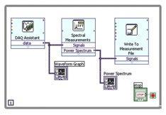
8 From Concept to Prototype Rapidly! Graphical System Design Platform Design Simulate Prototype LabVIEW Graphical System Design offers one tool, integrated flow Shorter learning curve Easier system integration Reduce the time to hardware rapid prototyping!

9 Getting Started in LabVIEW
 LabVIEW VIs contain")

10 LabVIEW Programs are Called Virtual Instruments (VIs) LabVIEW VIs contain three main components: 1. Front Panel 2. Block Diagram 3. Icon/Connector Pane


11 Front Panel & Controls Palette Numeric Control Controls Palette - contains the controls and indicators you use to create the front panel


12 Block Diagram & Functions Palette Math Function Front panel objects appear as terminals on the block diagram Contains the VIs, functions, and constants you use to create the block diagram
13 Dataflow Programming Block diagram execution Dependent on the flow of data Block diagram does NOT execute left to right Node executes when data is available to ALL input terminals Nodes supply data to all output terminals when done

14 LabVIEW Help Utilities Context Help Hover over function blocks for just-in-time help Help»Show Context Help Shortcut Keys: <Ctrl-H>

15 LabVIEW Help Utilities LabVIEW Help Select Help»LabVIEW Help Use the Detailed help link or button in the Context Help window Right-click an object and select Help from the shortcut menu
16 What is a Software Defined Radio? Software-Defined Radio (SDR) refers to the technology wherein software modules running on a generic hardware platform are used to implement radio functions..
 2.4 GHz & 5.5 GHz (NI-2921) 400 MHz 4.")


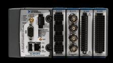
17 NI USRP Software Defined Radio Tunable RF Transceiver Front Ends Frequency Range 50 MHz 2.2 GHz (NI-2920) 2.4 GHz & 5.5 GHz (NI-2921) 400 MHz 4.4 GHz (NI-2922) Signal Processing and Synthesis NI LabVIEW to develop and explore algorithms NI Modulation Toolkit and LabVIEW add-ons to simulate or process live signals Applications FM Radio TV GPS GSM ZigBee Safety Radio OFDM Passive Radar Dynamic Spectrum Access 1 Gigabit Ethernet to PC Plug-and-play capability Up to 25 MS/s baseband IQ streaming

18 NI USRP Software Defined Radio RF Transceiver Baseband IQ Software Processing
19 SDR Components Tx Digital to Analog RF Upconversion Modulation RX RF Downconversion Analog to Digital Demodulation Signal Processing
20 NI-USRP Driver Software RX Settings
21 Signal Processing (PC) Receiver Path Software Radio Example TX SMA RX? SMA BUS
22 Signal Processing (PC) Receiver Path Software Radio Example TX SMA Amp DA C How fast? How many bits? BUS RX SMA Amp AD C 5GS/s for Wifi!?
23 Example: Sampling at 5 GS/s 2.5 GHz 50 MHz 0 Hz 2.4 GHz Signal of interest has 50 MHz bandwidth When we sample at 5 GS/s, we get all the data between GHz Only interested in 2.4 GHz +/- 25 MHz At this sampling rate, we collect much more data than we need How do we get around this?
24 Mixing
25 Signal After Mixing 50 MHz 0 Hz After mixing, signal of interest has 50 MHz bandwidth, but now it is a much lower frequency At this lower frequency, an ADC can capture the signal
26 Introduction to I and Q Acos( 2 f ct ) Acos( )cos(2 fct) I Acos( ) Q Asin( ) Acos( 2 f ct ) Asin( )sin(2 fct) I cos(2 fct) Qsin(2 fct) Note: I and Q capture Amplitude and Phase information

.")
27 IQ Modulator An IQ modulator multiplies I and Q by the carrier and carrier - 90 degrees, respectively. By summing two orthogonal data streams and a carrier, we get a phase modulator (any angle in the phase plane). If we add amplitude control, we get a vector modulator (any point in the phase plane). LO
28 Signal Processing (PC) Software Radio Receiver I( t)cos(2 f t) Q( t)sin(2 f t) c c RX Mixe r I(t) AD C BUS SMA Amp 0 o 90 o Tunable Oscillator f c Mixe r Q(t) RF Signal IQ Mixing Baseband f c = center frequency of interest AD C 100 MS/s ADC
29 Signal Processing (PC) Receiver Path Software Radio Example RF Signal IQ Mixing Baseband RX 1 SMA Switc h BUS RX 2 SMA Amp Tunable Oscillator Mixe r 0 o 90 o Mixe r LPF LPF 20 MHz LPF Low pass filters chosen to be below 50MHz Nyquist criteria Act as anti-aliasing filters Switch added to handle multiple different antennas 2 sampling chains effectively samples the signal twice AD C AD C 100 MS/s ADC 2 Sampling chains
30 Signal Processing (PC) Receiver Path USRP Example RF Signal IQ Mixing Baseband RX 1 SMA Switc h BUS RX 2 SMA Amp 900 MHz Tunable Oscillator Mixe r 0 o 90 o Mixe r LPF LPF 20 MHz LPF AD C AD C 100 MS/s ADC 3.2 Gb/s 1 Gb Etherne t Data Rate Calculation: 100 Million Samples/sec x 16 bits/sample x 2 = 3.2 Gigibits/second BUS = 1 Gb Ethernet down-conversion is needed to ~ 25 MS/s or less.
31 RX Control Signal Processing (PC) Receiver Path: USRP Example RF Signal IQ Mixing Baseband RX 1 SMA Switc h FPGA BUS RX 2 SMA Amp 900 MHz Tunable Oscillator Mixe r 0 o 90 o Mixe r LPF LPF 20 MHz LPF AD C AD C 100 MS/s ADC Onboard Signal Processing Onboard Signal Processing 1 Gb Etherne t Data Rate Calculation: 100 Million Samples/sec x 16 bits/sample x 2 = 3.2 Gigibits/second BUS = 1 Gb Ethernet down-conversion is needed to ~ 25 MS/s or less.


32 RX Control TX Control Signal Processing (PC) Radio NI USRP System Diagram RX 1 TX SMA 1 Amp Mixe r 0 o 90 o LPF DA C Onboard Signal Processing Mixe r LPF DA C Onboard Signal Processing Switc h Tunable Oscillator FPGA BUS RX 2 SMA Amp Mixe r 0 o 90 o LPF AD C Onboard Signal Processing Mixe r LPF AD C Onboard Signal Processing Tunable Oscillator NI USRP-2920 System Diagram
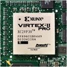
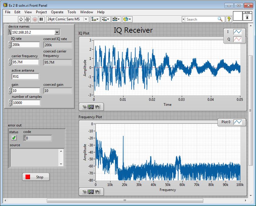
33 NI USRP-2920 Hardware Diagram 5. Gain 1. Device Name 4. Antenna 6. # Samples/ Buffer 2. IQ Rate 3. Carrier Frequenc y Analog RF Transceiver Fixed Function FPGA PC
34 USRP Configuring in 6 Parameters 1. Device Name IP address of one or multiple USRP 2. IQ Rate Quadrature sampling rate, equivalent to bandwidth 3. Carrier Frequency Frequency of interest 4. Antenna Select which antenna port to receive from 5. Gain Amplification of signal before digitizing the signal 6. Fetch size how many samples to acquire each fetch
35 Power (db) NI USRP RF Receive Parameters IQ Rate ~ Bandwidth 1 MHz 50 MHz 94.7 MHz Frequency
36 Power (db) NI USRP RF Receive Parameters Carrier Frequency 1 MHz 50 MHz 94.7 MHz Frequency
37 Power (db) NI USRP RF Receive Parameters Gain 1 MHz 50 MHz 94.7 MHz Frequency

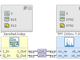
38 NI USRP RF Receive Parameters number of samples IQ 1 _ rate Time Domain * number _ samples fetch _ time

39 NI-USRP Driver Software Initialize Configur e Start Read IQ Stop Close


40 Exercise 1 buffered finite Acquisition
41 Demodulating Live FM Demodulate & listen to live FM radio LabVIEW programming fundamentals Integrating digital signal processing functions Using.m file script inside LabVIEW

42 Common Data Types Found in LabVIEW


43 Reviewing the Block Diagram Wire: Waveform Datatype Wire: Error Cluster

44 Waveform Data Type The waveform data type is used by LabVIEW to display and store periodic signal measurements. t0 Initial time of waveform dt Sample period Y Array of data samples Baseband IQ : Y is an array of complex numbers representing I and Q samples

45 Arrays An array consists of elements and dimensions Elements: data that make up the array Dimension: the length, height, or depth of an array Consider using arrays when you work with a collection of similar data and when you perform repetitive computations 49
46 Introduction to Clusters Data structure that groups data together Data may be of different types Analogous to struct in ANSI C Elements must be either all controls or all indicators Thought of as wires bundled into a cable Uses: Grouping variables Error handling Modulation toolkit

47 Loops While Loop Terminal counts iterations Always runs at least once Runs until stop condition is met For Loop Terminal counts iterations Runs according to input N of count terminal While Loop For Loop
 3.")
48 Demodulating Broadcast FM Radio FM radio can be demodulated in 3 steps: 1. Detect carrier phase 2. Unwrap the phase (remove discontinuities) 3. Compute the derivative (change in phase frequency) Baseband IQ Demodulated FM Detect phase Unwrap phase Differentiate phase

49 Unwrapping Phase Polar numbers consist of magnitude and phase Phase values from -180º to 180º Discontinuities exist as phase wraps back around Unwrap phase to eliminate discontinuities

50 Exercise 2A Demodulate and Listen to FM Radio

51 Demodulated Broadcast FM Mono Audio Left + Right 19 khz Stereo Pilot Stereo Audio Left - Right RBDS Direct Band Audos Subcarrier 0 30 Hz 15 khz 23 khz 38 khz 53 khz 57 khz khz khz khz 92 khz 99 khz


52 LabVIEW Models of Computation Dataflow C HDL Code Textual Math Multi-Rate DSP Simulation Statechart LabVIEW LabVIEW LabVIEW LabVIEW `` Desktop Real-Time FPGA MPU/MCU Personal Computers PXI Systems CompactRIO Single-Board RIO Custom Design

 Prototype your equations in the interactive")
53 Math with the LabVIEW MathScript Node Implement equations and algorithms textually Input and output variables created at the border Generally compatible with popular.m file script language Terminate statements with a semicolon to disable immediate output (Functions»Programming» Structures»MathScript) Prototype your equations in the interactive LabVIEW MathScript Window.

54 Frequency Demodulation Algorithm Detect phase Unwrap phase Differentiate phase

55 Exercise 3A Use a MathScript RT node
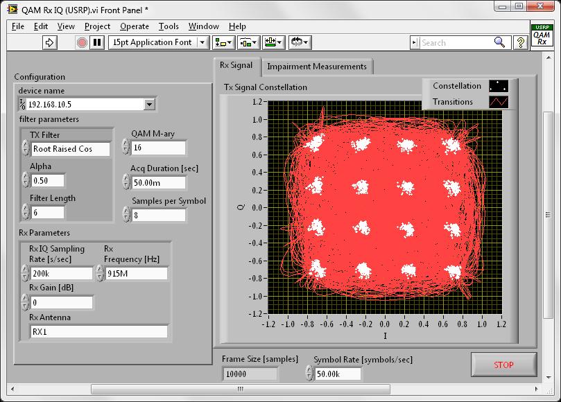
56 Communications Design in LabVIEW Modulation Toolkit Analog and Digital modulation formats AM, FM, PM ASK, FSK, MSK, GMSK, PAM, PSK, QAM Custom Visualization 2D and 3D Eye, Trellis, Constellation Modulation Analysis BER, MER, EVM, burst timing, frequency deviation, ρ (rho) Impairments Additive White Gaussian Noise (AWGN) DC offset, Quadrature skew, IQ gain imbalance, phase noise Equalization, Channel Coding, Channel Models

57 Exercise 3B Use Use Prebuilt IP
58 Digital Communications Explore a digital communications system Open and run a digital communications reference design Identify the part of a more advanced LabVIEW block diagram Overview of the modulation & demodulation process

59 Downconversion Demodulation Channel Decoding Source Decoding Source Coding Channel Coding Modulation Upconversion Digital Communication System Communications Channel
60 Digital Communication System NI Modulation Toolkit NI Modulation Toolkit


61 Digital Communication System NI Modulation Toolkit NI USRP NI Modulation Toolkit NI USRP

")

62 Communications Design in LabVIEW Modulation Toolkit Analog and Digital modulation formats AM, FM, PM ASK, FSK, MSK, GMSK, PAM, PSK, QAM Custom Visualization 2D and 3D Eye, Trellis, Constellation Modulation Analysis BER, MER, EVM, burst timing, frequency deviation, ρ (rho) Impairments Additive White Gaussian Noise (AWGN) DC offset, Quadrature skew, IQ gain imbalance, phase noise Equalization, Channel Coding, Channel Models

63 Advanced Digital Communications Topics
 Modulate Tx signal Demodulate Rx signal Reconstruct")
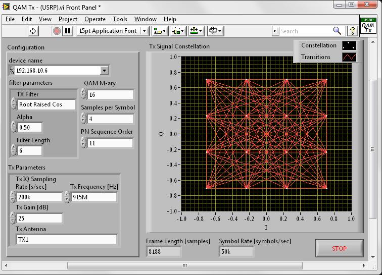
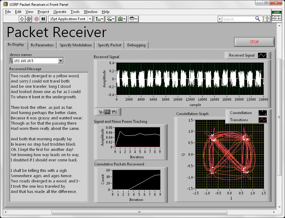
64 Packet-based Communication Link System Setup RF Signal Center Frequency: 915MHz Modulation Format: PSK packets Bit Rate: 400kbps NI USRP-2920 Transmitter NI USRP-2920 Receiver USRP control (Tx & Rx) Modulate Tx signal Demodulate Rx signal Reconstruct message

65 Packet-based Communication with LabVIEW
66 Packet Structure GUARD BAND SYNC SEQ PCKT NUM DATA PAD Field Length [bits] Description Guard Band 30 Allow initialization of Rx PLL, filters, etc Sync Sequence 20 Frame and Symbol Synchronization Packet Number 8 Range: Used for reordering of packets and detection of missing packets Data Variable length data field. Length detected dynamically at Rx end Pad 20 Allows for filter edge effects.

67 Transmitter Block Diagram

68 The Received Signal

69 Receiver Block Diagram

70 Demonstration : Packet Based Transceiver
 Key Benefits Affordable Accessible NI Supported TX & RX Real RF Signals Scales to")
71 Digital Communications Bundle Bundle Contents Two NI USRP Toolkits MIMO Cable Digital Comm Lab Manual Target Courses Communication Systems Digital & Wireless Communications Software Defined Radio (SDR) Key Benefits Affordable Accessible NI Supported TX & RX Real RF Signals Scales to Research


72 NI USRP Research Case Study: Cognitive Radio & Whitespace Large Scale Cognitive Radio Testbed Prototyping cognitive radio in LabVIEW Spectral sensing with blind detection Database driven geo-location with GPS Deployed in Munich, Germany LabVIEW software and the NI USRP hardware are key components of this research project, allowing the team to rapidly prototype and successfully deploy the first cognitive radio test bed of this kind. Dr. Paulo Marques, COGEU Aveiro, Portugal


73 NI USRP Research Case Study: Physical Layer Prototyping Dr. Murat Torlak Continuously monitoring multiple wifi channels Demodulation and descrambling of b beacon signals Identification of hotspots, tracking relative power levels Demodulate Descramble b SSID Decoding Carrier Detection Frequency Offset Estimation & Correction Demodulation & Descrambling Interpret the frame for SSID


74 Summary LabVIEW offers a graphical approach, shortening the design process, and tight hardware/software integration that allows for seamless transition from design to test NI provides a full spectrum of RF / Communications solutions: RF Test, Research and Education LabVIEW and NI USRP is an accessible, easy-to-use software defined radio platform
75 Next Steps Learn more about NI SDR and RF platforms Visit /sdr Download references from the Code sharing community Learn more about LabVIEW


76 NI LabVIEW Certifications Certified LabVIEW Architect Certified LabVIEW Developer On May 16 th, FREE Certified LabVIEW Associate Developer!! Certified LabVIEW Associate Developer

77 Thank you Questions
Spectral Monitoring/ SigInt
 RF Test & Measurement Spectral Monitoring/ SigInt Radio Prototyping Horizontal Technologies LabVIEW RIO for RF (FPGA-based processing) PXI Platform (Chassis, controllers, baseband modules) RF hardware
A Rapid Graphical Programming Approach to SDR Design and Prototyping with LabVIEW and the USRP
 A Rapid Graphical Programming Approach to SDR Design and Prototyping with LabVIEW and the USRP Filip Langenaken Academic Program Manager Benelux & Nordic National Instruments NI-USRP: a Platform for SDR
Bridge RF Design and Test Applications with NI SDR Platforms
 Bridge RF Design and Test Applications with NI SDR Platforms Jason Strydom Application Engineer National Instruments - Midrand The National Instruments Vision To do for test and measurement what the spreadsheet
Faculty of Information Engineering & Technology. The Communications Department. Course: Advanced Communication Lab [COMM 1005] Lab 6.
![Faculty of Information Engineering & Technology. The Communications Department. Course: Advanced Communication Lab [COMM 1005] Lab 6.](/thumbs/90/102233011.jpg "Faculty of Information Engineering & Technology. The Communications Department. Course: Advanced Communication Lab [COMM 1005] Lab 6.") Faculty of Information Engineering & Technology The Communications Department Course: Advanced Communication Lab [COMM 1005] Lab 6.0 NI USRP 1 TABLE OF CONTENTS 2 Summary... 2 3 Background:... 3 Software
Faculty of Information Engineering & Technology The Communications Department Course: Advanced Communication Lab [COMM 1005] Lab 6.0 NI USRP 1 TABLE OF CONTENTS 2 Summary... 2 3 Background:... 3 Software
Recap of Last 2 Classes
 Recap of Last 2 Classes Transmission Media Analog versus Digital Signals Bandwidth Considerations Attentuation, Delay Distortion and Noise Nyquist and Shannon Analog Modulation Digital Modulation What
NI USRP Lab: DQPSK Transceiver Design
 NI USRP Lab: DQPSK Transceiver Design 1 Introduction 1.1 Aims This Lab aims for you to: understand the USRP hardware and capabilities; build a DQPSK receiver using LabVIEW and the USRP. By the end of this
II. LAB. * Open the LabVIEW program (Start > All Programs > National Instruments > LabVIEW 2012 > LabVIEW 2012)
") II. LAB Software Required: NI LabVIEW 2012, NI LabVIEW 4.3 Modulation Toolkit. Functions and VI (Virtual Instrument) from the LabVIEW software to be used in this lab: niusrp Open Tx Session (VI), niusrp
II. LAB Software Required: NI LabVIEW 2012, NI LabVIEW 4.3 Modulation Toolkit. Functions and VI (Virtual Instrument) from the LabVIEW software to be used in this lab: niusrp Open Tx Session (VI), niusrp
RF and Communications
 RF and Communications Khaled Moselhy Field Application Engineer National Instruments Egypt National Instruments Our Commitment We equip engineers and scientists with tools that accelerate productivity,
SIGNAL PROCESSING WIRELESS COMMUNICATION RF TEST AND MEASUREMENT AUTOMOTIVE DEFENSE AND AEROSPACE
 SIGNAL PROCESSING WIRELESS COMMUNICATION RF TEST AND MEASUREMENT AUTOMOTIVE DEFENSE AND AEROSPACE Your One-Stop Provider for In-Vehicle Infotainment (IVI Test), Set-Top-Box, Digital TV Mobile TV test solution.
TU Dresden uses National Instruments Platform for 5G Research
 TU Dresden uses National Instruments Platform for 5G Research Wireless consumers insatiable demand for bandwidth has spurred unprecedented levels of investment from public and private sectors to explore
Getting Started Guide
 MaxEye Digital Audio and Video Signal Generation ISDB-T Signal Generation Toolkit Version 2.0.0 Getting Started Guide Contents 1 Introduction... 3 2 Installed File Location... 3 2.1 Soft Front Panel...
ni.com The NI PXIe-5644R Vector Signal Transceiver World s First Software-Designed Instrument
 The NI PXIe-5644R Vector Signal Transceiver World s First Software-Designed Instrument Agenda Hardware Overview Tenets of a Software-Designed Instrument NI PXIe-5644R Software Example Modifications Available
RF and Microwave Test and Design Roadshow 5 Locations across Australia and New Zealand
 RF and Microwave Test and Design Roadshow 5 Locations across Australia and New Zealand Advanced PXI Technologies Signal Recording, FPGA s, and Synchronization Outline Introduction to the PXI Architecture
Production Test and Spectral Monitoring
 1 Production Test and Spectral Monitoring Stephen Plumb Key RF Building Blocks Symbol Name Types Function Amplifier (2 port) Power Amplifier Low Noise Amplifier Amplify signal before transmission (high
From Antenna to Bits:
 From Antenna to Bits: Wireless System Design with MATLAB and Simulink Cynthia Cudicini Application Engineering Manager MathWorks cynthia.cudicini@mathworks.fr 1 Innovations in the World of Wireless Everything
Stephen Plumb National Instruments
 RF and Microwave Test and Design Roadshow Cape Town and Midrand October 2014 Stephen Plumb National Instruments Our Mission We equip engineers and scientists with tools that accelerate productivity, innovation,
Simulation of Analog Modulation and Demodulation Techniques in Virtual Instrumentation and Remote Lab
 Simulation of Analog Modulation and Demodulation Techniques in Virtual Instrumentation and Remote Lab https://doi.org/10.3991/ijoe.v13i10.7575 Nehru Kandasamy!! ", Nagarjuna Telagam, V.R Seshagiri Rao
June 09, 2014 Document Version: 1.1.0
 DVB-T2 Analysis Toolkit Data Sheet An ideal solution for SFN network planning, optimization, maintenance and Broadcast Equipment Testing June 09, 2014 Document Version: 1.1.0 Contents 1. Overview... 3
Radio with COTS Technologies. ATE Systems Engineer
 Signal Intelligence and Software-Defined Radio with COTS Technologies Sacha Emery ATE Systems Engineer 1 Agenda Introduction Optimised signal processing with multicore and FPGAs Timing and synchronisation
Getting Started Guide
 MaxEye ZigBee (IEEE 802.15.4) Measurement Suite Version 1.0.5.3 Getting Started Guide Table of Contents 1. Introduction...3 2. Installed File Location...3 3. Soft Front Panel...5 3.1 MaxEye ZigBee Signal
Using a design-to-test capability for LTE MIMO (Part 1 of 2)
") Using a design-to-test capability for LTE MIMO (Part 1 of 2) System-level simulation helps engineers gain valuable insight into the design sensitivities of Long Term Evolution (LTE) Multiple-Input Multiple-Output
Using a design-to-test capability for LTE MIMO (Part 1 of 2) System-level simulation helps engineers gain valuable insight into the design sensitivities of Long Term Evolution (LTE) Multiple-Input Multiple-Output
Do Engineering: Experimentation for Every Single Student. David Ore, District Sales Manager (NSW & ACT)
") Do Engineering: Experimentation for Every Single Student David Ore, District Sales Manager (NSW & ACT) The Era of Experimentation Theory Experimentation Engineering Grand Challenges Advance health informatics
Do Engineering: Experimentation for Every Single Student David Ore, District Sales Manager (NSW & ACT) The Era of Experimentation Theory Experimentation Engineering Grand Challenges Advance health informatics
Software Radio, GNU Radio, and the USRP Product Family
 Software Radio, GNU Radio, and the USRP Product Family Open Hardware for Software Radio Matt Ettus, matt@ettus.com Software Radio Simple, general-purpose hardware Do as much as possible in software Everyone's
Vector Signal Analyzer
 NI PXIe-5663, NI PXIe-5663E 10 MHz to 6.6 GHz frequency range 50 MHz instantaneous bandwidth (3 db) ±0.35 db typical flatness within 20 MHz bandwidth ±0.65 db typical amplitude accuracy
Case Study: and Test Wireless Receivers
 Case Study: Using New Technologies to Design and Test Wireless Receivers Agenda Architecture of a receiver Basic GPS Receiver Measurements Case Study 1: GPS Simulation How Testing Works Simulation vs.
Prototyping Next-Generation Communication Systems with Software-Defined Radio
 Prototyping Next-Generation Communication Systems with Software-Defined Radio Dr. Brian Wee RF & Communications Systems Engineer 1 Agenda 5G System Challenges Why Do We Need SDR? Software Defined Radio
RF and Microwave Test and Design Roadshow Cape Town & Midrand
 RF and Microwave Test and Design Roadshow Cape Town & Midrand Advanced PXI Technologies Signal Recording, FPGA s, and Synchronization Philip Ehlers Outline Introduction to the PXI Architecture PXI Data
PXIe Contents SPECIFICATIONS. 14 GHz and 26.5 GHz Vector Signal Analyzer
 SPECIFICATIONS PXIe-5668 14 GHz and 26.5 GHz Vector Signal Analyzer These specifications apply to the PXIe-5668 (14 GHz) Vector Signal Analyzer and the PXIe-5668 (26.5 GHz) Vector Signal Analyzer with
Research and Implementation of 2x2 MIMO-OFDM System with BLAST Using USRP-RIO
 Research and Implementation of 2x2 MIMO-OFDM System with BLAST Using USRP-RIO Jingyi Zhao, Yanhui Lu, Ning Wang *, and Shouyi Yang School of Information Engineering, Zheng Zhou University, China * Corresponding
SpectraTronix C700. Modular Test & Development Platform. Ideal Solution for Cognitive Radio, DSP, Wireless Communications & Massive MIMO Applications
 SpectraTronix C700 Modular Test & Development Platform Ideal Solution for Cognitive Radio, DSP, Wireless Communications & Massive MIMO Applications Design, Test, Verify & Prototype All with the same tool
2015 The MathWorks, Inc. 1
 2015 The MathWorks, Inc. 1 What s Behind 5G Wireless Communications? 서기환과장 2015 The MathWorks, Inc. 2 Agenda 5G goals and requirements Modeling and simulating key 5G technologies Release 15: Enhanced Mobile
A Software-Based Test Architecture for Emerging Wireless Technologies
 A Software-Based Test Architecture for Emerging Wireless Technologies Joseph E. Kovacs Product Marketing Manager RF and High Frequency Measurements National Instruments www.ni.com/rf My name is Joseph
What s Behind 5G Wireless Communications?
 What s Behind 5G Wireless Communications? Marc Barberis 2015 The MathWorks, Inc. 1 Agenda 5G goals and requirements Modeling and simulating key 5G technologies Release 15: Enhanced Mobile Broadband IoT
PGT313 Digital Communication Technology. Lab 3. Quadrature Phase Shift Keying (QPSK) and 8-Phase Shift Keying (8-PSK)
 and 8-Phase Shift Keying (8-PSK)") PGT313 Digital Communication Technology Lab 3 Quadrature Phase Shift Keying (QPSK) and 8-Phase Shift Keying (8-PSK) Objectives i) To study the digitally modulated quadrature phase shift keying (QPSK) and
PGT313 Digital Communication Technology Lab 3 Quadrature Phase Shift Keying (QPSK) and 8-Phase Shift Keying (8-PSK) Objectives i) To study the digitally modulated quadrature phase shift keying (QPSK) and
VST 6 GHz RF Vector Signal Transceiver (VST)
") VST 6 GHz RF Vector Signal Transceiver (VST) 2016 Datasheet The most important thing we build is trust Key features Vector signal analyser and generator in a single 3U x 3 slot wide PXIe module 65 MHz
VST 6 GHz RF Vector Signal Transceiver (VST) 2016 Datasheet The most important thing we build is trust Key features Vector signal analyser and generator in a single 3U x 3 slot wide PXIe module 65 MHz
Software Radio Network Testbed
 Software Radio Network Testbed Senior design student: Ziheng Gu Advisor: Prof. Liuqing Yang PhD Advisor: Xilin Cheng 1 Overview Problem and solution What is GNU radio and USRP Project goal Current progress
A DSP IMPLEMENTED DIGITAL FM MULTIPLEXING SYSTEM
 A DSP IMPLEMENTED DIGITAL FM MULTIPLEXING SYSTEM Item Type text; Proceedings Authors Rosenthal, Glenn K. Publisher International Foundation for Telemetering Journal International Telemetering Conference
VIAVI VST. Data Sheet. 6 GHz RF Vector Signal Transceiver (VST)
") Data Sheet VIAVI 6 GHz RF Vector Signal Transceiver () VIAVI Solutions The Vector Signal Transceiver () is an essential building block in RF communications test solutions supplied by VIAVI Solutions. Overview
Data Sheet VIAVI 6 GHz RF Vector Signal Transceiver () VIAVI Solutions The Vector Signal Transceiver () is an essential building block in RF communications test solutions supplied by VIAVI Solutions. Overview
DESIGN OF A MEASUREMENT PLATFORM FOR COMMUNICATIONS SYSTEMS
 DESIGN OF A MEASUREMENT PLATFORM FOR COMMUNICATIONS SYSTEMS P. Th. Savvopoulos. PhD., A. Apostolopoulos 2, L. Dimitrov 3 Department of Electrical and Computer Engineering, University of Patras, 265 Patras,
Enabling Future Wireless Technology Research through Flexible & Modular Platforms
 Enabling Future Wireless Technology Research through Flexible & Modular Platforms Richard Silley Business Development Manager RF & Communications Evolution of Wireless Communications How can we increase
New Technologies for Software Defined Radio. Farris Alhorr. National Instruments Business Development Manager, IndRAA
 New Technologies for Software Defined Radio Farris Alhorr National Instruments Business Development Manager, IndRAA Farris.alhorr@ni.com ni.com The World of Converged Devices More capability defined in
Addressing the Design-to-Test Challenges for SDR and Cognitive Radio
 Addressing the Design-to-Test Challenges Bob Cutler and Greg Jue, Agilent Technologies Software Defined Radios Flexibility Radio can support multiple waveforms: Different formats, Different revisions of
Digital Signal Analysis
 Digital Signal Analysis Objectives - Provide a digital modulation overview - Review common digital radio impairments Digital Modulation Overview Signal Characteristics to Modify Polar Display / IQ Relationship
Reconfigurable 6 GHz Vector Signal Transceiver with I/Q Interface
 SPECIFICATIONS PXIe-5645 Reconfigurable 6 GHz Vector Signal Transceiver with I/Q Interface Contents Definitions...2 Conditions... 3 Frequency...4 Frequency Settling Time... 4 Internal Frequency Reference...
PXI Vector Signal Transceivers
 PRODUCT FLYER PXI Vector Signal Transceivers CONTENTS PXI Vector Signal Transceivers Detailed View of PXIe-5840 RF Vector Signal Transceiver Key Features Software-Defined Architecture Platform-Based Approach
Getting Started Guide
 MaxEye IEEE 0.15.4 UWB Measurement Suite Version 1.0.0 Getting Started Guide 1 Table of Contents 1. Introduction... 3. Installed File Location... 3 3. Programming Examples... 4 3.1. 0.15.4 UWB Signal Generation...
Design Implementation Description for the Digital Frequency Oscillator
 Appendix A Design Implementation Description for the Frequency Oscillator A.1 Input Front End The input data front end accepts either analog single ended or differential inputs (figure A-1). The input
Wireless Communication Fading Modulation
 EC744 Wireless Communication Fall 2008 Mohamed Essam Khedr Department of Electronics and Communications Wireless Communication Fading Modulation Syllabus Tentatively Week 1 Week 2 Week 3 Week 4 Week 5
RF, HIL and Radar Test
 RF, HIL and Radar Test Abhay Samant Marketing Manager India, Russia and Arabia RF Hardware In The Loop Complex Radio Environment Components of RF HIL Communication Modems Channel Simulation GPS Simulation
An Introduction to Software Radio
 An Introduction to Software Radio (and a bit about GNU Radio & the USRP) Eric Blossom eb@comsec.com www.gnu.org/software/gnuradio comsec.com/wiki USENIX / Boston / June 3, 2006 What's Software Radio? It's
Wideband Spectral Measurement Using Time-Gated Acquisition Implemented on a User-Programmable FPGA
 Wideband Spectral Measurement Using Time-Gated Acquisition Implemented on a User-Programmable FPGA By Raajit Lall, Abhishek Rao, Sandeep Hari, and Vinay Kumar Spectral measurements for some of the Multiple
DEVELOPMENT OF SOFTWARE RADIO PROTOTYPE
 DEVELOPMENT OF SOFTWARE RADIO PROTOTYPE Isao TESHIMA; Kenji TAKAHASHI; Yasutaka KIKUCHI; Satoru NAKAMURA; Mitsuyuki GOAMI; Communication Systems Development Group, Hitachi Kokusai Electric Inc., Tokyo,
An OFDM Transmitter and Receiver using NI USRP with LabVIEW
 An OFDM Transmitter and Receiver using NI USRP with LabVIEW Saba Firdose, Shilpa B, Sushma S Department of Electronics & Communication Engineering GSSS Institute of Engineering & Technology For Women Abstract-
A LOW-COST SOFTWARE-DEFINED TELEMETRY RECEIVER
 A LOW-COST SOFTWARE-DEFINED TELEMETRY RECEIVER Michael Don U.S. Army Research Laboratory Aberdeen Proving Grounds, MD ABSTRACT The Army Research Laboratories has developed a PCM/FM telemetry receiver using
Simulating and Testing of Signal Processing Methods for Frequency Stepped Chirp Radar
 Test & Measurement Simulating and Testing of Signal Processing Methods for Frequency Stepped Chirp Radar Modern radar systems serve a broad range of commercial, civil, scientific and military applications.
From 2G to 4G UE Measurements from GSM to LTE. David Hall RF Product Manager
 From 2G to 4G UE Measurements from GSM to LTE David Hall RF Product Manager Agenda: Testing 2G to 4G Devices The progression of standards GSM/EDGE measurements WCDMA measurements LTE Measurements LTE theory
Radio Technology and Architectures. 1 ENGN4521/ENGN6521: Embedded Wireless L#1
 Radio Technology and Architectures 1 ENGN4521/ENGN6521: Embedded Wireless L#1 Radio (Architectures) Spectrum plan and legal issues Radio Architectures and components 2 ENGN4521/ENGN6521: Embedded Wireless
A New Complexity Reduced Hardware Implementation of 16 QAM Using Software Defined Radio
 A New Complexity Reduced Hardware Implementation of 16 QAM Using Software Defined Radio K.Bolraja 1, V.Vinod kumar 2, V.JAYARAJ 3 1Nehru Institute of Engineering and Technology, PG scholar, Dept. of ECE
Getting Started Guide
 MaxEye Digital Video Signal Generation Toolkit DVB-S2 Version 1.0.3.2 Getting Started Guide Contents 1. Introduction... 3 2. Installed File Location... 3 3. Programming Examples... 3 3.1. Create and Download
C700 A New Domain in Radio System Design & Verification
 C700 A New Domain in Radio System Design & Verification C700 A New Domain in Radio System Design & Verification A modular SDR (Software-Defined Radio) development and verification platform that allows
Advances in RF and Microwave Measurement Technology
 1 Advances in RF and Microwave Measurement Technology Chi Xu Certified LabVIEW Architect Certified TestStand Architect New Demands in Modern RF and Microwave Test In semiconductor and wireless, technologies
Chapter 3 Communication Concepts
 Chapter 3 Communication Concepts 1 Sections to be covered 3.1 General Considerations 3.2 Analog Modulation 3.3 Digital Modulation 3.4 Spectral Regrowth 3.7 Wireless Standards 2 Chapter Outline Modulation
Research on key digital modulation techniques using GNU Radio
 Research on key digital modulation techniques using GNU Radio Tianning Shen Yuanchao Lu I. Introduction Software Defined Radio (SDR) is the technique that uses software to realize the function of the traditional
TSTE17 System Design, CDIO. General project hints. Behavioral Model. General project hints, cont. Lecture 5. Required documents Modulation, cont.
 TSTE17 System Design, CDIO Lecture 5 1 General project hints 2 Project hints and deadline suggestions Required documents Modulation, cont. Requirement specification Channel coding Design specification
ELT Radio Architectures and Signal Processing. Motivation, Some Background & Scope
 Introduction ELT-44007/Intro/1 ELT-44007 Radio Architectures and Signal Processing Motivation, Some Background & Scope Markku Renfors Department of Electronics and Communications Engineering Tampere University
EXPERIMENT WISE VIVA QUESTIONS
 EXPERIMENT WISE VIVA QUESTIONS Pulse Code Modulation: 1. Draw the block diagram of basic digital communication system. How it is different from analog communication system. 2. What are the advantages of
Session 3. CMOS RF IC Design Principles
 Session 3 CMOS RF IC Design Principles Session Delivered by: D. Varun 1 Session Topics Standards RF wireless communications Multi standard RF transceivers RF front end architectures Frequency down conversion
Advances in RF and Microwave Measurement Technology
 1 Advances in RF and Microwave Measurement Technology Farris Alhorr Business Development Manager RF & Wireless Communication Farris.alhorr@ New Demands in Modern RF and Microwave Test In semiconductor
Software radio. Software program. What is software? 09/05/15 Slide 2
 Software radio Software radio Software program What is software? 09/05/15 Slide 2 Software radio Software program What is software? Machine readable instructions that direct processor to do specific operations
Report Due: 21:00, 3/17, 2017
 Report Due: 21:00, 3/17, 2017 In this course, we would like to learn how communication systems work from labs. For this purpose, LabVIEW is used to simulate these systems, and USRP is used to implement
LitePoint IQnxn MIMO Test Solution
 DATA SHEET LitePoint IQnxn MIMO Test Solution 2011 LitePoint Corporation. All rights reserved. Revision History Release Date Revision Change Description Jan 20, 2006 1.0 First Release April 6, 2007 2.1
100 MS/s, 16-Bit Arbitrary Waveform Generator with Onboard Signal Processing
 100 MS/s, 16-Bit Arbitrary Waveform Generator with Onboard Signal Processing NI PXIe-5442 NEW! Baseband and intermediate frequency generation Interpolation and pulse-shaping filters Carrier frequencies
Project in Wireless Communication Lecture 7: Software Defined Radio
 Project in Wireless Communication Lecture 7: Software Defined Radio FREDRIK TUFVESSON ELECTRICAL AND INFORMATION TECHNOLOGY Tufvesson, EITN21, PWC lecture 7, Nov. 2018 1 Project overview, part one: the
Redefining RF Instrumentation
 Redefining RF Instrumentation Agenda Introduction RF Platform PXI Architecture NI FPGA Platform RF Instrumentation redefined Wireless Everywhere The proliferation of mobile devices, including smartphones
CDMA Principle and Measurement
 CDMA Principle and Measurement Concepts of CDMA CDMA Key Technologies CDMA Air Interface CDMA Measurement Basic Agilent Restricted Page 1 Cellular Access Methods Power Time Power Time FDMA Frequency Power
9 Best Practices for Optimizing Your Signal Generator Part 2 Making Better Measurements
 9 Best Practices for Optimizing Your Signal Generator Part 2 Making Better Measurements In consumer wireless, military communications, or radar, you face an ongoing bandwidth crunch in a spectrum that
Reconfigurable 6 GHz RF Vector Signal Transceiver with 1 GHz Bandwidth
 CALIBRATION PROCEDURE PXIe-5840 Reconfigurable 6 GHz RF Vector Signal Transceiver with 1 GHz Bandwidth This document contains the verification procedures for the PXIe-5840 vector signal transceiver. Refer
PXIe Contents CALIBRATION PROCEDURE. Reconfigurable 6 GHz RF Vector Signal Transceiver with 200 MHz Bandwidth
 IBRATION PROCEDURE PXIe-5646 Reconfigurable 6 GHz Vector Signal Transceiver with 200 MHz Bandwidth This document contains the verification and adjustment procedures for the PXIe-5646 vector signal transceiver.
 UNIT 2 DIGITAL COMMUNICATION DIGITAL COMMUNICATION-Introduction The techniques used to modulate digital information so that it can be transmitted via microwave, satellite or down a cable pair is different
Triarchy VSG6G1C USB Vector RF Signal Generator Operating Manual
 Triarchy VSG6G1C USB Vector RF Signal Generator Operating Manual CW signal NB RF noise generator Analog modulation GMSK modulation Frequency sweeping Hopping with data Mod Page 1 of 27 8PSK GSM signal
Design and FPGA Implementation of an Adaptive Demodulator. Design and FPGA Implementation of an Adaptive Demodulator
 Design and FPGA Implementation of an Adaptive Demodulator Sandeep Mukthavaram August 23, 1999 Thesis Defense for the Degree of Master of Science in Electrical Engineering Department of Electrical Engineering
Productivity and flexibility for A/D applications
 Keysight Technologies W1902 Digital Modem Library Simulation Reference Library for Satellite and Military Communication Architects, Baseband Algorithm Researchers, and Component Verifiers in R&D Data Sheet
RF Basics 15/11/2013
 27 RF Basics 15/11/2013 Basic Terminology 1/2 dbm is a measure of RF Power referred to 1 mw (0 dbm) 10mW(10dBm), 500 mw (27dBm) PER Packet Error Rate [%] percentage of the packets not successfully received
A GENERAL SYSTEM DESIGN & IMPLEMENTATION OF SOFTWARE DEFINED RADIO SYSTEM
 A GENERAL SYSTEM DESIGN & IMPLEMENTATION OF SOFTWARE DEFINED RADIO SYSTEM 1 J. H.VARDE, 2 N.B.GOHIL, 3 J.H.SHAH 1 Electronics & Communication Department, Gujarat Technological University, Ahmadabad, India
Integrated Solutions for Testing Wireless Communication Systems
 TOPICS IN RADIO COMMUNICATIONS Integrated Solutions for Testing Wireless Communication Systems Dingqing Lu and Zhengrong Zhou, Agilent Technologies Inc. ABSTRACT Wireless communications standards have
Getting Started Guide
 MaxEye Digital Video Signal Analysis Toolkit DAB/T-DMB Version 1.0.1 Getting Started Guide Contents 1. Introduction... 3 2. Installed File Location... 3 3. Programming Examples... 3 3.1. Measure Modulation
Digital Wireless Measurement Solution
 Product Introduction Digital Wireless Measurement Solution Signal Analyzer MS2690A/MS2691A/MS2692A/MS2840A/MS2830A Vector Modulation Analysis Software MX269017A Vector Signal Generator MS269xA-020, MS2840A-020/021,
Selected answers * Problem set 6
 Selected answers * Problem set 6 Wireless Communications, 2nd Ed 243/212 2 (the second one) GSM channel correlation across a burst A time slot in GSM has a length of 15625 bit-times (577 ) Of these, 825
Meet the new E4438C ESG vector signal generator...
 Meet the new E4438C ESG vector signal generator... The Agilent E4438C ESG vector signal generator meets the needs of engineers who are designing and developing the next generation of wireless communication
ELT Receiver Architectures and Signal Processing Fall Mandatory homework exercises
 ELT-44006 Receiver Architectures and Signal Processing Fall 2014 1 Mandatory homework exercises - Individual solutions to be returned to Markku Renfors by email or in paper format. - Solutions are expected
and RTL-SDR Wireless Systems
 Laboratory 4 FM Receiver using MATLAB and RTL-SDR Wireless Systems TLEN 5830 Wireless Systems This Lab introduces the working of FM Receiver using MATLAB and Software Defined Radio This exercise encompasses
Mobile & Wireless Networking. Lecture 2: Wireless Transmission (2/2)
") 192620010 Mobile & Wireless Networking Lecture 2: Wireless Transmission (2/2) [Schiller, Section 2.6 & 2.7] [Reader Part 1: OFDM: An architecture for the fourth generation] Geert Heijenk Outline of Lecture
192620010 Mobile & Wireless Networking Lecture 2: Wireless Transmission (2/2) [Schiller, Section 2.6 & 2.7] [Reader Part 1: OFDM: An architecture for the fourth generation] Geert Heijenk Outline of Lecture
System-Level Time-Domain Behavioral Modeling for A Mobile WiMax Transceiver
 System-Level Time-Domain Behavioral Modeling for A Mobile WiMax Transceiver Jie He, Jun Seo Yang, Yongsup Kim, and Austin S. Kim HIDS Lab, Telecommunication R&D Center, Samsung Electronics jie.he@samung.com,
TRANSCOM Manufacturing & Education
 www.transcomwireless.com 1 G6 Vector Signal Generator Overview G6 Vector Signal Generator is a high performance vector signal generator. It can generate arbitrary wave signal, continuous wave signal, common
ThinkRF R5500. Real-Time Spectrum Analyzer. 9 khz to 8 GHz / 18 GHz / 27 GHz. Product Brochure and Technical Datasheet. Featuring
 Product Brochure and Technical Datasheet ThinkRF R5500 Real-Time Spectrum Analyzer 9 khz to 8 GHz / 18 GHz / 27 GHz Featuring Real-Time Bandwidth (RTBW) up to 100 MHz Spurious Free Dynamic Range (SFDR)
B SCITEQ. Transceiver and System Design for Digital Communications. Scott R. Bullock, P.E. Third Edition. SciTech Publishing, Inc.
 Transceiver and System Design for Digital Communications Scott R. Bullock, P.E. Third Edition B SCITEQ PUBLISHtN^INC. SciTech Publishing, Inc. Raleigh, NC Contents Preface xvii About the Author xxiii Transceiver
A Design-to-Test Methodology for SDR and Cognitive Radio
 A Design-to-Test Methodology for SDR and Cognitive Radio Authors: Greg Jue & Bob Cutler, Agilent Technologies Agenda SDR Waveform Challenges SDR Waveform Design SDR Hardware Testing Cognitive Radio Algorithm
LEARN TELECOMMUNICATIONS BY SIMULATION. Jeremy Clark VE3PKC
 LEARN TELECOMMUNICATIONS BY SIMULATION Jeremy Clark VE3PKC ISBN 978-0-9880490-0-0 Clark Telecommunications/Jeremy Clark June 2012 All rights reserved. No part of this work shall be reproduced, stored in
Signal generators. Modular design for user-friendly solutions
 GENERAL PURPOSE 43985/1 FIG 1 Visionary: The new Vector Signal Generator R&S SMU200A offers two complete signal generators with digital modulation capability in a single instrument and facilitates the
EKT 314/4 LABORATORIES SHEET
 EKT 314/4 LABORATORIES SHEET WEEK DAY HOUR 4 1 2 PREPARED BY: EN. MUHAMAD ASMI BIN ROMLI EN. MOHD FISOL BIN OSMAN JULY 2009 Creating a Typical Measurement Application 5 This chapter introduces you to common