Lab 3 Final report: Embedded Systems Digital Potentiometer Subsystem TEAM: RAR
|
|
|
- Marilyn Sparks
- 5 years ago
- Views:
Transcription
1 Lab 3 Final report: Embedded Systems Digital Potentiometer Subsystem TEAM: RAR EE 300W, Section 6 Professor Tim Wheeler Rui Xia, Yuanpeng Liao and Ashwin Ramnarayanan
2 Table of Contents Introduction...2 Rationale Implementation...3 Explanation of Code and Circuitry...4 Verification Testing...11 Validation Testing...19 Results from Integrated System...19 Discussion Conclusion...24 Appendices
3 Introduction As the complexity of today s computer system grows, we can no long use a single system to meet the requirement. At this time, we need to utilize embedded system to break the main function into several subsystems. The purpose of this lab is to integrate the four subsystems together and analyze the function of a black box. The four subsystems contain digital-to-analog converter subsystem (D2A), digital potentiometer subsystem (Digipot), analog to digital converter subsystem (A2D) and keypad subsystem. D2A subsystem and Digipot subsystem will generate and input a waveform into the black box. The output of the black box will be analyzed and sampled by the A2D subsystem. Users can control the entire embedded system using the keypad subsystem. By comparing the input and output of the black box, we can analyze the behavior of the black box. Our team is assigned to build the digital potentiometer subsystem. Digitpot subsystem is used to scale the output of D2A subsystem and input the scaled waveform into the black box. The output amplitude of the digital potentiometer subsystem is selected by the keypad subsystem. It is crucial to generate a desired and consistent input to the black box because we need to compare the input and output of the black box. Rationale Theory of Operation In digital potentiometer subsystem, we need to scale the DAC subsystem output (0-3.3V) to have a voltage range of 0 to +1, 2, 3, 4, or 5 V. Digital potentiometer is the most important part in our subsystem because we need it to change the gain of the amplifier and thus scale the input waveform. The digital potentiometer works as an analog potentiometer. The wiper position Dn of the DigiPot selects the two resistors values RA and RB. RA = RAB * (256 Dn) / 256 and RB = (RAB * Dn) / 256. RA + RB = RAB = 50kΩ for MCP41050 DigiPot. We choose to place RA between the input and inverting terminal, and RB on the feedback path. Once we change the wiper position 2
4 based on the C++ code, the gain of the inverting amplifier will also change to our desired value. In our C++ code, the subsystem outputs different scaled amplitudes using 5 case statements. Theory of Interfaces Mebed is connected to PC to load C++ code to our circuit. We use SPI to communicate the mbed to the DigiPot. The connections used were MOSI (Master-Out Slave-In) and SCLK (clock). PuTTY can send and receive messages from the mebed using USB port. CAN bus connects our subsystem and the keypad subsystem so that the commands received from keypad subsystem will send to our subsystem. Implementation Circuitry: Our subsystem should scale and map a 0 to 3.3V input from DAC to a 0 to 1V, 2V, 3V, 4V and 5V by selection. The selection of output range will be made via mbed according to the can message from the keypad subsystem. An inverting amplifier circuit model with a voltage divider is chosen. 3
5 Single-supply, programmable, inverting gain amplifier using a digital potentiometer Vin is the subsystem input and Vref is connected to ground. The gain equation is now Vout = - Vin(Rwb/Rwa) Variable gain Rwb / Rwa allows us to output a range no matter it is larger or smaller than the input voltage. A second inverting amplifier with gain of 1 is added at Vout to produce a positive output. In experiment, we found that the resistors used in the second amplifier should be much larger than the resistors in the first one to make an output waveform without any clipping. We chose 2M ohm which is much larger than 50 k ohm (Rab). Also, a 10k ohm resistor is added at Rb to stabilize the performance when Rwb is low. 4
 Rwb resistance (ohm) 1 3.95 k 2 12.64 k 3 18.57 k 4 22.87 k 5 29.")
6 Circuit design Our equation is now: Vout = Vin((Rwb+10k)/Rwa) Where Vin = 3.3V, Vout = 1V, 2V, 3V, 4V, 5V, Rwb + Rwa = 50k ohm. By solving the equation, we get the resistance values of Rwb for different outputs. Output (V) Rwb resistance (ohm) k k k k k The hex wiper position is calculated by the equation 5
7 Dn = 256 * Rwb / Rab where Rab = 50 k. Adjustments are made to the calculated values based on experiments. The final wiper positions are: Output (V) Hex wiper position 1 0x14 2 0x21 3 0x31 4 0x33 5 0x46 Code: An LPC 1768 mbed microcontroller will be coded with C language to realize the following functions: 1. It gets the CAN-bus message from keypad subsystem via MCP 2551 CAN transceiver to determine desired digital potentiometer output 2. It writes corresponding hex wiper position values to MCP digital potentiometer. In the code, the can message will be read and stored by this line CANMessage msg; We used an if statement to test if there is any message received by the mbed and show in LEDs: if(can2.read(msg)) { 6
8 printf("message received: %d\n", msg.data[0]); led2 =!led2; } Then, a case statement is used to determine the desired wiper position to the digipot. For each case, a wiper position is selected and a message is printed to show the case And the following lines will write the selected wiper position: cs = 0; spi.write(0x13); z = setvoltage(msg); spi.write(z); cs = 1; 7
9 cs=0 will select the chip first. The position 0x13 is the selected command bit. The selected wiper position is written next. Finally, cs = 1 would deselect the chip. Verification Test: Our subsystem, digipot, is responsible to map the output of Digital-to-Analog Converter system (0 3.3V, 1Hz or 10 Hz solenoid or square wave) to a waveform of different amplitude (0 0-1V, 2V, 3V,4V or 5V). And the output amplitude is selected by keypad via a local CAN bus. And the output of our system will be directly sent to the black box. Our module and interface connection: 8

10 Testing Method: 9

11 We used a function generator outputting a sinusoidal wave spanning 0 to +3.3 V to mimic the function of DAC subsystem. The Can bus message is set in code for output range selection. The output waveform is observed with an oscilloscope. The plots of the oscilloscope are recorded for different cases: 10

12 1V: 2V: 11

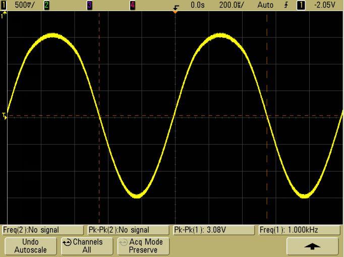
13 3V: 4V: 12


14 5V: Validation test: 13
15 Most of our result waveform almost exactly matched the desired amplitude. And all the percentage errors are no more than 10% Desired voltage(v) Actual voltage(v) Percentage Error (%) Our subsystem successfully fulfills the requirements. Our subsystem receives command from keypad, converts the output of DAC and output a waveform to the black box. The accuracy of subsystem s output can directly affect the observation of the black box behavior. Digipot is an indispensable part in the whole system. Result from integration: We didn t finish integration, But we tried to use our part and oscilloscope to identify the black box. We tried various kind of input to the black box. By observe the reading from oscilloscope (ADC subsystem), we determined the behavior of the black box. Firstly, the output of black box does not depend on the input frequency. The output is the same for both 1Hz and 10Hz. We also observe that the output amplitude is no more than 1V in any case. Trying different input value, we observed that the gain is about 0.1. The black box behavior can be express as: 14
 Discussion The design that we chose met the requirements by using one MBED microcontroller, one digital potentiometer, two op amps and one CAN transceiver.")
16 Vout = 1V- 0.1 Vin Our group thinks that the black box is an inverting amplifier with a 1 volt offset. Vout = - Vin (1k/10k) *(1 + 1k/10k) Discussion The design that we chose met the requirements by using one MBED microcontroller, one digital potentiometer, two op amps and one CAN transceiver. The utility of this design is in the usage of the digital potentiometer as a resistor on the op amp design whose resistance can be changed as needed. This is better than the alternatives of using a lot more components and breadboard space. The team used the provided Agilent function generator to generate our input signal. We also used the two power supplies provided to us to get our +15V,-15V and +5V supply. The team initially faced a non working circuit simply because the ground was not shared. Eventually, after following the proper wiring, the circuit began functioning to a certain degree. In the beginning, the circuit produced nothing but noise. This was corrected when we debugged our circuit to find that the voltage input was not getting through to the 15
17 MBED. After rewiring, we obtained a periodic function and resembled a wave. This was due to incorrect resistor values as we found out later on. After, the values were changed, the code had to be changed in the case structures for the HEX values. Finally, after the final debugging we were able to obtain our sine wave. This entire process took up the entirety of our time. Thus, the team was unable to work with the other teams for a significant amount of time. The teams were unable to link the CAN buses together to get a common voltage signal through them and control the black box using the keypad. This is the result of time management and communication issues both within and outside the team. This would be the main area of improvement for the group moving forward. Finally, the teams tried identifying what was in the black box. We were successfully able to get the 1 Volt offset answer correct but were unable to calculate the slope. The final waveform function was: Y = -0.1X + 1 V Future areas of improvement would involve proper communication amongst the team members in order to manage time efficiently. A lot of work was required to be done outside the given lab period of time which was not used properly. Value Statement: In this lab, we are required to communicate with other groups to accomplish an integrated project. This is the first time we encounter this setting. However, we can certainly imagine that this kind of scenario is far from rarely happen in an engineer s career. We were a little confused at the beginning. This resulted in the failure that we could not finish the integration. This experience greatly enhances our communication skill and prepares us for the inevitable. Technically, this is also the first time for most of us to use LCP 1768 mbed and an online compiler. Being able to work with various languages and compilers is a great contributor to a successful career. This lab shows us a continuously learning process example and gives us some experience about it. 16


18 Conclusion Team RAR successfully completed the DigiPot subsystem that received the input signal and could control the resistor values in 5 different cases. The teams were unsuccessful in integrating the subsystems together whose entire purpose was to divide the work instead of loading all of it on one program. The utility of this project goes into security and control systems. The CAN buses enables us to integrate multiple subsystems into one giant process. This allows for continuous improvement to a given process and simultaneously makes debugging much easier for the engineers. Appendixes Appendixes A: Gantt chart Appendixes B: Bill of materials 17
19 Appendixes C: mbed code 18
20 19

21 Appendixes D: Block diagram 20
Lab 3: Embedded Systems
 THE PENNSYLVANIA STATE UNIVERSITY EE 3OOW SECTION 3 FALL 2015 THE DREAM TEAM Lab 3: Embedded Systems William Stranburg, Sean Solley, Sairam Kripasagar Table of Contents Introduction... 3 Rationale... 3
Digital-to-Analog Converter. Lab 3 Final Report
 Digital-to-Analog Converter Lab 3 Final Report The Ion Cannons: Shrinand Aggarwal Cameron Francis Nicholas Polito Section 2 May 1, 2017 1 Table of Contents Introduction..3 Rationale..3 Theory of Operation.3
Embedded Test System. Design and Implementation of Digital to Analog Converter. TEAM BIG HERO 3 John Sopczynski Karim Shik-Khahil Yanzhe Zhao
 Embedded Test System Design and Implementation of Digital to Analog Converter TEAM BIG HERO 3 John Sopczynski Karim Shik-Khahil Yanzhe Zhao EE 300W Section 1 Spring 2015 Big Hero 3 DAC 2 INTRODUCTION (KS)
EE 210 Lab Exercise #5: OP-AMPS I
 EE 210 Lab Exercise #5: OP-AMPS I ITEMS REQUIRED EE210 crate, DMM, EE210 parts kit, T-connector, 50Ω terminator, Breadboard Lab report due at the ASSIGNMENT beginning of the next lab period Data and results
BME 3512 Bioelectronics Laboratory Five - Operational Amplifiers
 BME 351 Bioelectronics Laboratory Five - Operational Amplifiers Learning Objectives: Be familiar with the operation of a basic op-amp circuit. Be familiar with the characteristics of both ideal and real
UNIVERSITI MALAYSIA PERLIS
 UNIVERSITI MALAYSIA PERLIS ANALOG ELECTRONICS II EMT 212 2009/2010 EXPERIMENT # 3 OP-AMP (OSCILLATORS) 1 1. OBJECTIVE: 1.1 To demonstrate the Wien bridge oscillator 1.2 To demonstrate the RC phase-shift
BME/ISE 3512 Bioelectronics. Laboratory Five - Operational Amplifiers
 BME/ISE 3512 Bioelectronics Laboratory Five - Operational Amplifiers Learning Objectives: Be familiar with the operation of a basic op-amp circuit. Be familiar with the characteristics of both ideal and
EE 368 Electronics Lab. Experiment 10 Operational Amplifier Applications (2)
") EE 368 Electronics Lab Experiment 10 Operational Amplifier Applications (2) 1 Experiment 10 Operational Amplifier Applications (2) Objectives To gain experience with Operational Amplifier (Op-Amp). To
EE 368 Electronics Lab Experiment 10 Operational Amplifier Applications (2) 1 Experiment 10 Operational Amplifier Applications (2) Objectives To gain experience with Operational Amplifier (Op-Amp). To
Data Conversion and Lab Lab 4 Fall Digital to Analog Conversions
 Digital to Analog Conversions Objective o o o o o To construct and operate a binary-weighted DAC To construct and operate a Digital to Analog Converters Testing the ADC and DAC With DC Input Testing the
Intro To Engineering II for ECE: Lab 7 The Op Amp Erin Webster and Dr. Jay Weitzen, c 2014 All rights reserved.
 Lab 7: The Op Amp Laboratory Objectives: 1) To introduce the operational amplifier or Op Amp 2) To learn the non-inverting mode 3) To learn the inverting mode 4) To learn the differential mode Before You
EE 300W Lab 2: Optical Theremin Critical Design Review
 EE 300W Lab 2: Optical Theremin Critical Design Review Team Drunken Tinkers: S6G8 Levi Nicolai, Harvish Mehta, Justice Lee October 21, 2016 Abstract The objective of this lab is to create an Optical Theremin,
The Operational Amplifier This lab is adapted from the Kwantlen Lab Manual
 Name: Partner(s): Desk #: Date: Purpose The Operational Amplifier This lab is adapted from the Kwantlen Lab Manual The purpose of this lab is to examine the functions of operational amplifiers (op amps)
When you have completed this exercise, you will be able to relate the gain and bandwidth of an op amp
 Op Amp Fundamentals When you have completed this exercise, you will be able to relate the gain and bandwidth of an op amp In general, the parameters are interactive. However, in this unit, circuit input
DEPARTMENT OF ELECTRICAL ENGINEERING LAB WORK EE301 ELECTRONIC CIRCUITS
 DEPARTMENT OF ELECTRICAL ENGINEERING LAB WORK EE301 ELECTRONIC CIRCUITS EXPERIMENT : 3 TITLE : Operational Amplifier (Op-Amp) OUTCOME : Upon completion of this unit, the student should be able to: 1. Gain
ECE ECE285. Electric Circuit Analysis I. Spring Nathalia Peixoto. Rev.2.0: Rev Electric Circuits I
 ECE285 Electric Circuit Analysis I Spring 2014 Nathalia Peixoto Rev.2.0: 140124. Rev 2.1. 140813 1 Lab reports Background: these 9 experiments are designed as simple building blocks (like Legos) and students
CHAPTER ELEVEN - Interfacing With the Analog World
 CHAPTER ELEVEN - Interfacing With the Analog World 11.1 (a) Analog output = (K) x (digital input) (b) Smallest change that can occur in the analog output as a result of a change in the digital input. (c)
DEPARTMENT OF ELECTRICAL ENGINEERING LAB WORK EE301 ELECTRONIC CIRCUITS
 DEPARTMENT OF ELECTRICAL ENGINEERING LAB WORK EE301 ELECTRONIC CIRCUITS EXPERIMENT : 5 TITLE : ACTIVE FILTERS OUTCOME : Upon completion of this unit, the student should be able to: 1. gain experience with
ECE3204 D2015 Lab 1. See suggested breadboard configuration on following page!
 ECE3204 D2015 Lab 1 The Operational Amplifier: Inverting and Non-inverting Gain Configurations Gain-Bandwidth Product Relationship Frequency Response Limitation Transfer Function Measurement DC Errors
LAB #10: Analog Interfacing
 CS/EE 3720 Handout #10 Spring 2004 Myers LAB #10: Analog Interfacing You must checkoff this lab during your lab section of the week of April 19th. Lab writeup is due in class on April 27th. NO LATE CHECKOFFS
Michael Tang TA: Ketobi 7/18/13
 Michael Tang TA: Ketobi 7/18/13 Lab Station #5 Section 1 Partners: Matt, Ryan Task 1: Basic Inverting Amplifier For this task, a basic inverting amplifier was needed to be designed to amplify the output
THE PENNSYLVANIA STATE UNIVERSITY. Lab 2: Designing Optical Theremin Instrument. EE 300W Section 001. Nathaniel Houtz, Ji Eun Shin, Peter Wu 2/22/2013
 THE PENNSYLVANIA STATE UNIVERSITY Lab 2: Designing Optical Theremin Instrument EE 300W Section 001 Nathaniel Houtz, Ji Eun Shin, Peter Wu 2/22/2013 1 ABSTRACT A simple Theremin must be able to produce
ECE 363 FINAL (F16) 6 problems for 100 pts Problem #1: Fuel Pump Controller (18 pts)
 6 problems for 100 pts Problem #1: Fuel Pump Controller (18 pts)") ECE 363 FINAL (F16) NAME: 6 problems for 100 pts Problem #1: Fuel Pump Controller (18 pts) You are asked to design a high-side switch for a remotely operated fuel pump. You decide to use the IRF9520 power
ECE 363 FINAL (F16) NAME: 6 problems for 100 pts Problem #1: Fuel Pump Controller (18 pts) You are asked to design a high-side switch for a remotely operated fuel pump. You decide to use the IRF9520 power
ENSC 220 Lab #2: Op Amps Vers 1.2 Oct. 20, 2005: Due Oct. 24, 2004
 ENSC 220 Lab #2: Op Amps Vers 1.2 Oct. 20, 2005: Due Oct. 24, 2004 OBJECTIVE: Using the circuits below you can study op amps and characterize their behavior. Comparator Inverting Amplifier PREPARATION:
Laboratory 4 Operational Amplifier Department of Mechanical and Aerospace Engineering University of California, San Diego MAE170
 Laboratory 4 Operational Amplifier Department of Mechanical and Aerospace Engineering University of California, San Diego MAE170 Megan Ong Diana Wu Wong B01 Tuesday 11am April 28 st, 2015 Abstract: The
UNIVERSITI MALAYSIA PERLIS
 UNIVERSITI MALAYSIA PERLIS ANALOG ELECTRONICS CIRCUIT II EKT 214 Semester II (2012/2013) EXPERIMENT # 3 OP-AMP (DIFFERENTIATOR & INTEGRATOR) Analog Electronics II (EKT214) 2012/2013 EXPERIMENT 3 Op-Amp
ENGN Analogue Electronics Digital PC Oscilloscope
 Faculty of Engineering and Information Technology Department of Engineering ENGN3227 - Analogue Electronics Digital PC Oscilloscope David Dries u2543318 Craig Gibbons u2543813 James Moran u4114563 Ranmadhu
Practical 2P12 Semiconductor Devices
 Practical 2P12 Semiconductor Devices What you should learn from this practical Science This practical illustrates some points from the lecture courses on Semiconductor Materials and Semiconductor Devices
EE 210: CIRCUITS AND DEVICES
 EE 210: CIRCUITS AND DEVICES OPERATIONAL AMPLIFIERS PART II This is the second of two laboratory sessions that provide an introduction to the op amp. In this session you will study three amplifiers designs:
EE 230 Lab Lab 9. Prior to Lab
 MOS transistor characteristics This week we look at some MOS transistor characteristics and circuits. Most of the measurements will be done with our usual lab equipment, but we will also use the parameter
ECE4902 C Lab 7
 ECE902 C2012 - Lab MOSFET Differential Amplifier Resistive Load Active Load PURPOSE: The primary purpose of this lab is to measure the performance of the differential amplifier. This is an important topology
EE 3305 Lab I Revised July 18, 2003
 Operational Amplifiers Operational amplifiers are high-gain amplifiers with a similar general description typified by the most famous example, the LM741. The LM741 is used for many amplifier varieties
When input, output and feedback voltages are all symmetric bipolar signals with respect to ground, no biasing is required.
 1 When input, output and feedback voltages are all symmetric bipolar signals with respect to ground, no biasing is required. More frequently, one of the items in this slide will be the case and biasing
Lab: Operational Amplifiers
 Page 1 of 6 Laboratory Goals Familiarize students with Integrated Circuit (IC) construction on a breadboard Introduce the LM 741 Op-amp and its applications Design and construct an inverting amplifier
STATION NUMBER: LAB SECTION: RC Oscillators. LAB 5: RC Oscillators ELECTRICAL ENGINEERING 43/100. University Of California, Berkeley
 YOUR NAME: YOUR SID: Lab 5: RC Oscillators EE43/100 Spring 2013 Kris Pister YOUR PARTNER S NAME: YOUR PARTNER S SID: STATION NUMBER: LAB SECTION: Pre- Lab GSI Sign- Off: Pre- Lab Score: /40 In- Lab Score:
Basic operational amplifier circuits In this lab exercise, we look at a variety of op-amp circuits. Note that this is a two-period lab.
 Basic operational amplifier circuits In this lab exercise, we look at a variety of op-amp circuits. Note that this is a two-period lab. Prior to Lab 1. If it has been awhile since you last used the lab
INDIANA UNIVERSITY, DEPT. OF PHYSICS, P400/540 LABORATORY FALL Laboratory #6: Operational Amplifiers
 INDIANA UNIVERSITY, DEPT. OF PHYSICS, P400/540 LABORATORY FALL 008 Laboratory #: Operational Amplifiers Goal: Study the use of the operational amplifier in a number of different configurations: inverting
UNIVERSITI MALAYSIA PERLIS
 UNIVERSITI MALAYSIA PERLIS ANALOG ELECTRONICS II EKT 214 Semester II (2013/2014) EXPERIMENT # 4 OP-AMP (COMPARATOR BASICS) EXPERIMENT 4 Op-Amp (Comparator Basics) 1. OBJECTIVE: 1.1 To demonstrate the op-amp
Each individual is to report on the design, simulations, construction, and testing according to the reporting guidelines attached.
 EE 352 Design Project Spring 2015 FM Receiver Revision 0, 03-02-15 Interim report due: Friday April 3, 2015, 5:00PM Project Demonstrations: April 28, 29, 30 during normal lab section times Final report
LABORATORY EXPERIMENT. Infrared Transmitter/Receiver
 LABORATORY EXPERIMENT Infrared Transmitter/Receiver (Note to Teaching Assistant: The week before this experiment is performed, place students into groups of two and assign each group a specific frequency
Operational Amplifiers
 Objective Operational Amplifiers Understand the basics and general concepts of operational amplifier (op amp) function. Build and observe output of a comparator and an amplifier (inverting amplifier).
Laboratory 8 Operational Amplifiers and Analog Computers
 Laboratory 8 Operational Amplifiers and Analog Computers Introduction Laboratory 8 page 1 of 6 Parts List LM324 dual op amp Various resistors and caps Pushbutton switch (SPST, NO) In this lab, you will
Rowan University Freshman Clinic I Lab Project 2 The Operational Amplifier (Op Amp)
") Rowan University Freshman Clinic I Lab Project 2 The Operational Amplifier (Op Amp) Objectives Become familiar with an Operational Amplifier (Op Amp) electronic device and it operation Learn several basic
Rowan University Freshman Clinic I Lab Project 2 The Operational Amplifier (Op Amp) Objectives Become familiar with an Operational Amplifier (Op Amp) electronic device and it operation Learn several basic
DEPARTMENT OF ELECTRICAL ENGINEERING AND COMPUTER SCIENCE MASSACHUSETTS INSTITUTE OF TECHNOLOGY CAMBRIDGE, MASSACHUSETTS 02139
 DEPARTMENT OF ELECTRICAL ENGINEERING AND COMPUTER SCIENCE MASSACHUSETTS INSTITUTE OF TECHNOLOGY CAMBRIDGE, MASSACHUSETTS 019.101 Introductory Analog Electronics Laboratory Laboratory No. READING ASSIGNMENT
Data Conversion and Lab Lab 1 Fall Operational Amplifiers
 Operational Amplifiers Lab Report Objectives Materials See separate report form located on the course webpage. This form should be completed during the performance of this lab. 1) To construct and operate
EE320L Electronics I. Laboratory. Laboratory Exercise #3. Operational Amplifier Application Circuits. Angsuman Roy
 EE320L Electronics I Laboratory Laboratory Exercise #3 Operational Amplifier Application Circuits By Angsuman Roy Department of Electrical and Computer Engineering University of Nevada, Las Vegas Objective:
University of California at Berkeley Donald A. Glaser Physics 111A Instrumentation Laboratory
 Published on Instrumentation LAB (http://instrumentationlab.berkeley.edu) Home > Lab Assignments > Digital Labs > Digital Circuits II Digital Circuits II Submitted by Nate.Physics on Tue, 07/08/2014-13:57
Physics 303 Fall Module 4: The Operational Amplifier
 Module 4: The Operational Amplifier Operational Amplifiers: General Introduction In the laboratory, analog signals (that is to say continuously variable, not discrete signals) often require amplification.
Lab 4: Analysis of the Stereo Amplifier
 ECE 212 Spring 2010 Circuit Analysis II Names: Lab 4: Analysis of the Stereo Amplifier Objectives In this lab exercise you will use the power supply to power the stereo amplifier built in the previous
ESE 150 Lab 04: The Discrete Fourier Transform (DFT)
") LAB 04 In this lab we will do the following: 1. Use Matlab to perform the Fourier Transform on sampled data in the time domain, converting it to the frequency domain 2. Add two sinewaves together of differing
LAB 04 In this lab we will do the following: 1. Use Matlab to perform the Fourier Transform on sampled data in the time domain, converting it to the frequency domain 2. Add two sinewaves together of differing
UC Berkeley, EECS Department EECS 40/42/100 Lab LAB3: Operational Amplifier UID:
 UC Berkeley, EECS Department EECS 40/42/100 Lab LAB3: Operational Amplifier UID: B. E. Boser 1 Enter the names and SIDs for you and your lab partner into the boxes below. Name 1 SID 1 Name 2 SID 2 Sensor
E84 Lab 3: Transistor
 E84 Lab 3: Transistor Cherie Ho and Siyi Hu April 18, 2016 Transistor Testing 1. Take screenshots of both the input and output characteristic plots observed on the semiconductor curve tracer with the following
LABORATORY 4. Palomar College ENGR210 Spring 2017 ASSIGNED: 3/21/17
 LABORATORY 4 ASSIGNED: 3/21/17 OBJECTIVE: The purpose of this lab is to evaluate the transient and steady-state circuit response of first order and second order circuits. MINIMUM EQUIPMENT LIST: You will
Optical Theremin Critical Design Review Yanzhe Zhao, Mason Story, Nicholas Czesak March
 Optical Theremin Critical Design Review Yanzhe Zhao, Mason Story, Nicholas Czesak March-07-2015 Abstract A theremin is a musical instrument whose tone and pitch can be controlled without physical contact.
High Voltage Waveform Sensor
 High Voltage Waveform Sensor Computer Engineering Senior Project Nathan Stump Spring 2013 Statement of Purpose The purpose of this project was to build a system to measure the voltage waveform of a discharging
C H A P T E R 02. Operational Amplifiers
 C H A P T E R 02 Operational Amplifiers The Op-amp Figure 2.1 Circuit symbol for the op amp. Figure 2.2 The op amp shown connected to dc power supplies. The Ideal Op-amp 1. Infinite input impedance 2.
EE4902 C Lab 7
 EE4902 C2007 - Lab 7 MOSFET Differential Amplifier Resistive Load Active Load PURPOSE: The primary purpose of this lab is to measure the performance of the differential amplifier. This is an important
Lab 1: Non-Ideal Operational Amplifier and Op-Amp Circuits
 Lab 1: Non-Ideal Operational Amplifier and Op-Amp Circuits 1. Learning Outcomes In this lab, the students evaluate characteristics of the non-ideal operational amplifiers. Students use a simulation tool
Massachusetts Institute of Technology Department of Electrical Engineering and Computer Science Circuits & Electronics Spring 2005
 Massachusetts Institute of Technology Department of Electrical Engineering and Computer Science 6.002 Circuits & Electronics Spring 2005 Lab #2: MOSFET Inverting Amplifiers & FirstOrder Circuits Introduction
LAB 4: OPERATIONAL AMPLIFIER CIRCUITS
 LAB 4: OPERATIONAL AMPLIFIER CIRCUITS ELEC 225 Introduction Operational amplifiers (OAs) are highly stable, high gain, difference amplifiers that can handle signals from zero frequency (dc signals) up
Experiment No. 4 The LM 741 Operational Amplifier
 Experiment No. 4 The LM 741 Operational Amplifier By: Prof. Gabriel M. Rebeiz The University of Michigan EECS Dept. Ann Arbor, Michigan The LM * 741 is the most widely used op-amp in the world due to its
CHARACTERISTICS OF OPERATIONAL AMPLIFIERS - II
 CHARACTERISTICS OF OPERATIONAL AMPLIFIERS - II OBJECTIVE The purpose of the experiment is to examine non-ideal characteristics of an operational amplifier. The characteristics that are investigated include
Analog I/O. ECE 153B Sensor & Peripheral Interface Design Winter 2016
 Analog I/O ECE 153B Sensor & Peripheral Interface Design Introduction Anytime we need to monitor or control analog signals with a digital system, we require analogto-digital (ADC) and digital-to-analog
Lab 6: Instrumentation Amplifier
 Lab 6: Instrumentation Amplifier INTRODUCTION: A fundamental building block for electrical measurements of biological signals is an instrumentation amplifier. In this lab, you will explore the operation
EK307 Active Filters and Steady State Frequency Response
 EK307 Active Filters and Steady State Frequency Response Laboratory Goal: To explore the properties of active signal-processing filters Learning Objectives: Active Filters, Op-Amp Filters, Bode plots Suggested
University of Pittsburgh
 University of Pittsburgh Experiment #6 Lab Report Active Filters and Oscillators Submission Date: 7/9/28 Instructors: Dr. Ahmed Dallal Shangqian Gao Submitted By: Nick Haver & Alex Williams Station #2
ECEN Network Analysis Section 3. Laboratory Manual
 ECEN 3714----Network Analysis Section 3 Laboratory Manual LAB 07: Active Low Pass Filter Oklahoma State University School of Electrical and Computer Engineering. Section 3 Laboratory manual - 1 - Spring
LINEAR APPLICATIONS OF OPERATIONAL AMPLIFIERS
 LINEAR APPLICATIONS OF OPERATIONAL AMPLIFIERS OBJECTIVE The purpose of the experiment is to examine the linear applications of an operational amplifier. The applications that are designed and analyzed
Lab 2 Operational Amplifier
 Lab 2 Operational Amplifier Last Name: First Name: Student Number: Lab Section: Monday Tuesday Wednesday Thursday Friday TA Signature: Note: The Pre-Lab section must be completed prior to the lab session.
EE320L Electronics I. Laboratory. Laboratory Exercise #2. Basic Op-Amp Circuits. Angsuman Roy. Department of Electrical and Computer Engineering
 EE320L Electronics I Laboratory Laboratory Exercise #2 Basic Op-Amp Circuits By Angsuman Roy Department of Electrical and Computer Engineering University of Nevada, Las Vegas Objective: The purpose of
ECE Lab #4 OpAmp Circuits with Negative Feedback and Positive Feedback
 ECE 214 Lab #4 OpAmp Circuits with Negative Feedback and Positive Feedback 20 February 2018 Introduction: The TL082 Operational Amplifier (OpAmp) and the Texas Instruments Analog System Lab Kit Pro evaluation
CHARACTERIZATION OF OP-AMP
 EXPERIMENT 4 CHARACTERIZATION OF OP-AMP OBJECTIVES 1. To sketch and briefly explain an operational amplifier circuit symbol and identify all terminals. 2. To list the amplifier stages in a typical op-amp
Dedan Kimathi University of technology. Department of Electrical and Electronic Engineering. EEE2406: Instrumentation. Lab 2
 Dedan Kimathi University of technology Department of Electrical and Electronic Engineering EEE2406: Instrumentation Lab 2 Title: Analogue to Digital Conversion October 2, 2015 1 Analogue to Digital Conversion
DEPARTMENT OF ELECTRICAL ENGINEERING AND COMPUTER SCIENCE MASSACHUSETTS INSTITUTE OF TECHNOLOGY CAMBRIDGE, MASSACHUSETTS 02139
 DEPARTMENT OF ELECTRICAL ENGINEERING AND COMPUTER SCIENCE MASSACHUSETTS INSTITUTE OF TECHNOLOGY CAMBRIDGE, MASSACHUSETTS 019 Spring Term 00.101 Introductory Analog Electronics Laboratory Laboratory No.
PROGRAMMABLE INTRACRANIAL SELF- STIMULATION (ICSS) CURRENT STIMULATOR
 CURRENT STIMULATOR") instrumentation and software for research PROGRAMMABLE INTRACRANIAL SELF- STIMULATION (ICSS) CURRENT STIMULATOR PHM-15X USER S MANUAL DOC-012 Rev. 1.8 Copyright 2012 All Rights Reserved Med Associates
instrumentation and software for research PROGRAMMABLE INTRACRANIAL SELF- STIMULATION (ICSS) CURRENT STIMULATOR PHM-15X USER S MANUAL DOC-012 Rev. 1.8 Copyright 2012 All Rights Reserved Med Associates
EXPERIMENT NUMBER 8 Introduction to Active Filters
 EXPERIMENT NUMBER 8 Introduction to Active Filters i-1 Preface: Preliminary exercises are to be done and submitted individually. Laboratory hardware exercises are to be done in groups. This laboratory
LABORATORY 3 v1 CIRCUIT ELEMENTS
 University of California Berkeley Department of Electrical Engineering and Computer Sciences EECS 100, Professor Bernhard Boser LABORATORY 3 v1 CIRCUIT ELEMENTS The purpose of this laboratory is to familiarize
EE 3111 Lab 7.1. BJT Amplifiers
 EE 3111 Lab 7.1 BJT Amplifiers BJT Amplifier Device/circuit that alters the amplitude of a signal, while keeping input waveform shape BJT amplifiers run the BJT in active mode. Forward current gain is
Circuit Layout Techniques And Tips (Part III of VI) by Bonnie C. Baker and Ezana Haile, Microchip Technology Inc.
 by Bonnie C. Baker and Ezana Haile, Microchip Technology Inc.") Circuit Layout Techniques And Tips (Part III of VI) by Bonnie C. Baker and Ezana Haile, Microchip Technology Inc. The major classes of parasitic generated by the PC board layout come in the form of resistors,
Circuit Layout Techniques And Tips (Part III of VI) by Bonnie C. Baker and Ezana Haile, Microchip Technology Inc. The major classes of parasitic generated by the PC board layout come in the form of resistors,
t w = Continue to the next page, where you will draw a diagram of your design.
 Name EET 1131 Lab #13 Multivibrators OBJECTIVES: 1. To design and test a monostable multivibrator (one-shot) using a 555 IC. 2. To analyze and test an astable multivibrator (oscillator) using a 555 IC.
Single-phase Variable Frequency Switch Gear
 Single-phase Variable Frequency Switch Gear Eric Motyl, Leslie Zeman Advisor: Professor Steven Gutschlag Department of Electrical and Computer Engineering Bradley University, Peoria, IL May 13, 2016 ABSTRACT
University of Portland EE 271 Electrical Circuits Laboratory. Experiment: Op Amps
 University of Portland EE 271 Electrical Circuits Laboratory Experiment: Op Amps I. Objective The objective of this experiment is to learn how to use an op amp circuit to prevent loading and to amplify
Laboratory 9. Required Components: Objectives. Optional Components: Operational Amplifier Circuits (modified from lab text by Alciatore)
") Laboratory 9 Operational Amplifier Circuits (modified from lab text by Alciatore) Required Components: 1x 741 op-amp 2x 1k resistors 4x 10k resistors 1x l00k resistor 1x 0.1F capacitor Optional Components:
Laboratory 9 Operational Amplifier Circuits (modified from lab text by Alciatore) Required Components: 1x 741 op-amp 2x 1k resistors 4x 10k resistors 1x l00k resistor 1x 0.1F capacitor Optional Components:
WAVE SHAPING CIRCUITS USING OPERATIONAL AMPLIFIERS
 WAVE SHAPING CIRCUITS USING OPERATIONAL AMPLIFIERS OBJECTIVE The purpose of the experiment is to design the wave shaping circuits like Clippers, Clampers and Schmitt trigger using op-amps. EQUIPMENT REQUIRED
Feed Forward Linearization of Power Amplifiers
 EE318 Electronic Design Lab Report, EE Dept, IIT Bombay, April 2007 Feed Forward Linearization of Power Amplifiers Group-D16 Nachiket Gajare ( 04d07015) < nachiketg@ee.iitb.ac.in> Aditi Dhar ( 04d07030)
The measurement of loop gain in feedback seismometers Brett M. Nordgren April 9, 1999 Rev.
 Introduction The measurement of loop gain in feedback seismometers Brett M. Nordgren http://bnordgren.org/contactb.html April 9, 1999 Rev. October 5, 2004 In reading the messages coming through PSN-L,
Operational Amplifiers
 Operational Amplifiers Reading Horowitz & Hill handout Notes, Chapter 9 Introduction and Objective In this lab we will examine op-amps. We will look at a few of their vast number of uses and also investigate
BME 3512 Bioelectronics Laboratory Six - Active Filters
 BME 5 Bioelectronics Laboratory Six - Active Filters Learning Objectives: Understand the basic principles of active filters. Describe the differences between active and passive filters. Laboratory Equipment:
How to Wire an Inverting Amplifier Circuit
 How to Wire an Inverting Amplifier Circuit Figure 1: Inverting Amplifier Schematic Introduction The purpose of this instruction set is to provide you with the ability to wire a simple inverting amplifier
Lab Exercise 6: Digital/Analog conversion
 Lab Exercise 6: Digital/Analog conversion Introduction In this lab exercise, you will study circuits for analog-to-digital and digital-to-analog conversion Preparation Before arriving at the lab, you should
LT Spice Getting Started Very Quickly. First Get the Latest Software!
 LT Spice Getting Started Very Quickly First Get the Latest Software! 1. After installing LT Spice, run it and check to make sure you have the latest version with respect to the latest version available
Purpose: 1) to investigate the electrical properties of a diode; and 2) to use a diode to construct an AC to DC converter.
 to investigate the electrical properties of a diode; and 2) to use a diode to construct an AC to DC converter.") Name: Partner: Partner: Partner: Purpose: 1) to investigate the electrical properties of a diode; and 2) to use a diode to construct an AC to DC converter. The Diode A diode is an electrical device which
Name: Partner: Partner: Partner: Purpose: 1) to investigate the electrical properties of a diode; and 2) to use a diode to construct an AC to DC converter. The Diode A diode is an electrical device which
10: AMPLIFIERS. Circuit Connections in the Laboratory. Op-Amp. I. Introduction
 10: AMPLIFIERS Circuit Connections in the Laboratory From now on you will construct electrical circuits and test them. The usual way of constructing circuits would be to solder each electrical connection
Lab 9: Operational amplifiers II (version 1.5)
") Lab 9: Operational amplifiers II (version 1.5) WARNING: Use electrical test equipment with care! Always double-check connections before applying power. Look for short circuits, which can quickly destroy
Lab 9: Operational amplifiers II (version 1.5) WARNING: Use electrical test equipment with care! Always double-check connections before applying power. Look for short circuits, which can quickly destroy
USER MANUAL FOR THE LM2901 QUAD VOLTAGE COMPARATOR FUNCTIONAL MODULE
 USER MANUAL FOR THE LM2901 QUAD VOLTAGE COMPARATOR FUNCTIONAL MODULE LM2901 Quad Voltage Comparator 1 5/18/04 TABLE OF CONTENTS 1. Index of Figures....3 2. Index of Tables. 3 3. Introduction.. 4-5 4. Theory
Week 8 AM Modulation and the AM Receiver
 Week 8 AM Modulation and the AM Receiver The concept of modulation and radio transmission is introduced. An AM receiver is studied and the constructed on the prototyping board. The operation of the AM
PURPOSE: NOTE: Be sure to record ALL results in your laboratory notebook.
 EE4902 Lab 9 CMOS OP-AMP PURPOSE: The purpose of this lab is to measure the closed-loop performance of an op-amp designed from individual MOSFETs. This op-amp, shown in Fig. 9-1, combines all of the major
RF System: Baseband Application Note
 Jimmy Hua 997227433 EEC 134A/B RF System: Baseband Application Note Baseband Design and Implementation: The purpose of this app note is to detail the design of the baseband circuit and its PCB implementation
ENGR 210 Lab 12: Analog to Digital Conversion
 ENGR 210 Lab 12: Analog to Digital Conversion In this lab you will investigate the operation and quantization effects of an A/D and D/A converter. A. BACKGROUND 1. LED Displays We have been using LEDs
Common-Source Amplifiers
 Lab 2: Common-Source Amplifiers Introduction The common-source stage is the most basic amplifier stage encountered in CMOS analog circuits. Because of its very high input impedance, moderate-to-high gain,
Assignment 11. 1) Using the LM741 op-amp IC a circuit is designed as shown, then find the output waveform for an input of 5kHz
 Using the LM741 op-amp IC a circuit is designed as shown, then find the output waveform for an input of 5kHz") Assignment 11 1) Using the LM741 op-amp IC a circuit is designed as shown, then find the output waveform for an input of 5kHz Vo = 1 x R1Cf 0 Vin t dt, voltage output for the op amp integrator 0.1 m 1
Assignment 11 1) Using the LM741 op-amp IC a circuit is designed as shown, then find the output waveform for an input of 5kHz Vo = 1 x R1Cf 0 Vin t dt, voltage output for the op amp integrator 0.1 m 1