I/O Module USER S MANUAL
|
|
|
- Norman Glenn
- 5 years ago
- Views:
Transcription
1 Machine Controller MP2000 Series I/O Module USE S MANUA Model JAPMC-IO23 JAPMC-DO2300 IO-01 D1 D2 D3 D4 MODE D5 D6 D7 D8 IO-04 I/O UN CN1 FU CN2 Mounting Modules IO-01/IO-02 Module IO-04/IO-05 Module IO-06 Module DO-01 Module MANUA NO. SIEP C A
2 Copyright 2008 YASKAWA EECTIC COPOATION All rights reserved. No part of this publication may be reproduced, stored in a retrieval system, or transmitted, in any form, or by any means, mechanical, electronic, photocopying, recording, or otherwise, without the prior written permission of Yaskawa. No patent liability is assumed with respect to the use of the information contained herein. Moreover, because Yaskawa is constantly striving to improve its high-quality products, the information contained in this manual is subject to change without notice. Every precaution has been taken in the preparation of this manual. Nevertheless, Yaskawa assumes no responsibility for errors or omissions. Neither is any liability assumed for damages resulting from the use of the information contained in this publication.
3 Using this Manual This Manual describes MP2000 Series Machine Controller I/O Modules, IO-01, IO-02, IO-04, IO-05, IO-06, and DO-01. ead this Manual thoroughly before using IO-01, IO-02, IO-04, IO-05, IO-06, and DO-01. Keep this in a safe, convenient location for future reference. Basic Terms Unless otherwise specified, the following definitions are used: MP2000 Series Machine Controller : MP2100M, MP2200, MP2300, MP2300S, and MP2500MD Machine Controllers PC : Programmable ogic Controller PP : Programming Panel MPE720 : The Programming Device Software or a personal computer running the Programming Device Software Graphic Symbols Used in this Manual The graphic symbols used in this manual indicate the following type of information. This symbol is used to indicate important information that should be memorized or minor precautions, such as precautions that will result in alarms if not heeded. Indication of everse Signals In this manual, the names of reverse signals (ones that are valid when low) are written with a forward slash (/) before the signal name, as shown in the following example: <Notation Examples> S-ON = /S-ON P-CON = /P-CON Indication of I/O egister Numbers In this manual, the I/O register numbers are written as shown in the following example: Input register number: IW hh (or I hh) Indicates the input leading register number (IW ) + hh (offset value from the leading register number in hexadecimal). Output register number: OW hh (or O hh) Indicates output leading register number (OW ) + hh (offset value from the leading register number in hexadecimal). <Example> When hh is 02, the register number is IW 02 or OW 02. 3
4 elated Manuals The following table lists the manuals relating to the MP2000 Series Machine Controller I/O Modules. efer to these manuals as required. Manual Name Manual Number Contents Machine Controller MP2100/MP2100M User s Manual Design and Maintenance Machine Controller MP2200 User s Manual Machine Controller MP2300 Basic Module User s Manual Machine Controller MP2300S Basic Module User s Manual Machine Controller MP2500/MP2500M/ MP2500D/MP2500MD User s Manual Machine Controller MP2000 Series Motion Module User s Manual Built-in SVB/SVB-01 Module Machine Controller MP2000 Series Communication Module User s Manual Machine Controller MP900/MP2000 Series User s Manual, adder Programming Machine Controller MP900/MP2000 Series User s Manual, Motion Programming Engineering Tool for MP2000 Series Machine Controller MPE720 Version 6 User s Manual Machine Controller MP900/MP2000 Series MPE720 Software for Programming Device User s Manual Machine Controller MP900/MP2000 Series New adder Editor Programming Manual Machine Controller MP900/MP2000 Series New adder Editor User s Manual SIEPC SIEPC SIEPC SIEPC SIEPC SIEPC SIEPC SIEZ-C SIEZ-C SIEPC SIEPC SIEZ-C SIEZ-C Describes how to use the MP2100 and MP2100M Machine Controllers. Describes how to use the MP2200 Machine Controller and the modules that can be connected. Describes how to use the MP2300 Basic Module and the modules that can be connected. Describes how to use the MP2300S Basic Module and the modules that can be connected. Describes how to use the MP2500, MP2500M, MP2500D, and MP2500MD Machine Controllers. Provides a detailed description on the MP2000- series Machine Controller built-in SVB Module and slot-mounting optional SVB-01 Module. Provides the information on the Communication Module that can be connected to MP2000 Series Machine Controller and the communication methods. Describes the instructions used in MP900/MP2000 ladder programming. Describes the instructions used in MP900/MP2000 motion programming. Describes how to install and operate the programming tool MPE720 version 6 for MP2000 Series Machine Controllers. Describes how to install and operate the MP900/ MP2000 Series programming system (MPE720). Describes the programming instructions of the New adder Editor, which assists MP900/MP2000 Series design and maintenance. Describes the operating methods of the New adder Editor, which assists MP900/MP2000 Series design and maintenance. Copyrights DeviceNet is a registered trademark of the ODVA (Open DeviceNet Venders Association). Ethernet is a registered trademark of the Xerox Corporation. POFIBUS is a trademark of the POFIBUS User Organization. MPINK is a trademark of the Yaskawa Electric Corporation. MECHATOINK is a trademark of the MECHATOINK Members Association. Other product names and company names are the trademarks or registered trademarks of the respective company. TM and the mark do not appear with product or company names in this manual. 4
5 Safety Information The following conventions are used to indicate precautions in this manual. Information marked as shown below is important for the safety of the user. Always read this information and heed the precautions that are provided. The conventions are as follows: WANING CAUTION Indicates precautions that, if not heeded, could possibly result in loss of life or serious injury. Indicates precautions that, if not heeded, could result in relatively serious or minor injury, or property damage. can lead to serious results depend- If not heeded, even precautions classified under ing on circumstances. CAUTION POHIBITED MANDATOY Indicates prohibited actions. Specific prohibitions are indicated inside. For example, indicates no fire or open flame. Indicates mandatory actions. Specific actions are indicated inside. For example, indicates that grounding is required. 5
6 Safety Precautions The following precautions are for checking products on delivery, storage, transportation, installation, wiring, operation, application, inspection, and disposal. These precautions are important and must be observed. General Precautions WANING Before starting operation while connected to the machine, ensure that an emergency stop procedure has been provided and is working correctly. There is a risk of injury. Do not touch anything inside the product. There is a risk of electrical shock. Always keep the front cover attached when power is being supplied. There is a risk of electrical shock. Observe all procedures and precautions given in this manual for trial operation. Operating mistakes while the servomotor and machine are connected can cause damage to the machine or even accidents resulting in injury or death. Do not remove the front cover, cables, connector, or options while power is being supplied. There is a risk of electrical shock. Do not damage, pull on, apply excessive force to, place heavy objects on, or pinch cables. There is a risk of electrical shock, operational failure of the product, or burning. Do not attempt to modify the product in any way. There is a risk of injury or device damage. Do not approach the machine when there is a momentary interruption to the power supply. When power is restored, the MP2000 Series Machine Controller or machine connected to it may start operation suddenly. Provide suitable safety measures to protect people when operation restarts. There is a risk of injury. Do not allow installation, disassembly, or repairs to be performed by anyone other than specified personnel. There is a risk of electrical shock or injury. 6
7 Storage and Transportation CAUTION Do not store or install the product in locations subject to the following. There is a risk of fire, electric shock, and machine product damage. Direct sunlight Ambient temperatures exceeding the storage or operating conditions Ambient humidity exceeding the storage or operating conditions Extreme changes in temperature that would result in condensation Corrosive or flammable gas Excessive dust, dirt, salt, or metallic powder Water, oil, or chemicals Vibration or shock Do not overload the product during transportation. There is a risk of injury or an accident. Never subject the product to an atmosphere containing halogen (fluorine, chlorine, bromine, or iodine) during transportation or installation. There is a risk of device damage or an accident. If disinfectants or insecticides must be used to treat packing materials such as wooden frames, pallets, or plywood, the packing materials must be treated before the product is packaged, and methods other than fumigation must be used. Example: Heat treatment, where materials are kiln-dried to a core temperature of 56 C for 30 minutes or more. If the electronic products, which include stand-alone products and products installed in machines, are packed with fumigated wooden materials, the electrical components may be greatly damaged by the gases or fumes resulting from the fumigation process. In particular, disinfectants containing halogen, which includes chlorine, fluorine, bromine, or iodine can contribute to the erosion of the capacitors. Installation CAUTION Never use the product in locations subject to water, corrosive atmospheres, or flammable gas, or near burnable objects. There is a risk of electrical shock or fire. Do not step on the product or place heavy objects on the product. There is a risk of injury. Do not block the air exhaust port on the product. Do not allow foreign objects to enter the product. There is a risk of element deterioration inside, an accident, or fire. Always mount the product in the specified orientation. There is a risk of an accident. Do not subject the product to strong shock. There is a risk of an accident. 7
8 Wiring CAUTION Check the wiring to be sure it has been performed correctly. There is a risk of motor run-away, injury, or an accident. Always use a power supply of the specified voltage. There is a risk of burning. In places with poor power supply conditions, take all steps necessary to ensure that the input power is supplied within the specified voltage range. There is a risk of device damage. Install breakers and other safety measures to provide protection against shorts in external wiring. There is a risk of fire. Provide sufficient shielding when using the product in the locations subject to the following. There is a risk of device damage. Noise, such as from static electricity Strong electromagnetic or magnetic fields adiation Near power lines Selecting, Separating, and aying External Cables CAUTION Consider the following items when selecting the I/O signal lines (external cables) to connect the product to external devices. Mechanical strength Noise interference Wiring distance Signal voltage, etc. Separate the I/O signal lines from the power lines both inside and outside the control box to reduce the influence of noise from the power lines. If the I/O signal lines and power lines are not separated properly, malfunctioning may result. Example of Separated External Cables Steel separator Power circuit cables General control circuit cables Digital I/O signal cables Maintenance and Inspection Precautions CAUTION Do not attempt to disassemble the product. There is a risk of electrical shock or injury. Do not change wiring while power is being supplied. There is a risk of electrical shock or injury. 8
9 Disposal Precautions CAUTION Dispose of the product as general industrial waste. 9
10 Contents Using this Manual Safety Information Safety Precautions Mounting Modules Applicable Machine Controllers and Corresponding Version Applicable Machine Controllers Corresponding CPU Version and MPE720 Version Mounting and emoving a Module on Machine Controller Mounting an I/O Module emoving an I/O Module Self-configuration Executing Self-configuration Example of I/O egister Allocation by Self-Configuration Module Configuration Definition Displaying the Module Configuration Window Module Configuration Window Changing the Module Configuration Definition IO-01/IO-02 Module Outline of IO-01/IO-02 Modules Outline of Functions IO-01/IO-02 Module Appearance and Connector External Dimensions Specifications ED Indicators and Switch Settings Specifications of IO-01/IO-02 Module Connections Connector Specifications Cable Specifications Input Circuits Output Circuit Pulse Input Circuit IO-01/IO-02 Module Connections IO-01/IO-02 Module Details ocal I/O Configuration Counter Module Configuration Details of Counter Functions Pulse Counting Modes Pulse Count Function Coincidence Output and Coincidence Interrupt Functions PI atch Function Axis Type Selection Electronic Gear Function Outline Settings Electronic Gear Setting Examples Precautions When Using Electronic Gears
11 3 IO-04/IO-05 Module Outline of IO-04/IO-05 Modules Outline of Functions IO-04/IO-05 Module Appearance and Connector External Dimensions Specifications ED Indicators Specifications of IO-04/IO-05 Module Connections Connector Specifications Cable Specifications Input Circuit Output Circuit IO-04 Module Connections IO-05 Module Connections IO-04/ IO-05 Module Details Displaying the ocal I/O Window ocal I/O Configuration Details IO-06 Module Outline of IO-06 Module Outline of Functions IO-06 Module Appearance and Connector External Dimensions Specifications ED Indicators Analog I/O Characteristics Specifications of IO-06 Module Connections Connector Specifications Cable Specifications Digital Input Circuits Digital Output Circuit Analog Input Circuit Analog Output Circuit Pulse Input Circuit IO-06 Module Connections Wiring for Noise Control IO-06 Module Details MIXIO Configuration Setting the I/O Offset/Gain Counter Module Configuration Details of Counter Functions Pulse Counting Modes Pulse Count Function Coincidence Output and Coincidence Interrupt Functions PI atch Function Axis Type Selection Electronic Gear Function Outline Settings Electronic Gear Setting Examples Precautions When Using Electronic Gears
12 5 DO-01 Module Outline of DO-01 Module Outline of Functions DO-01 Module Appearance and Connector External Dimensions Specifications ED Indicators Specifications of DO-01 Module Connections Connector Specifications Cable Specifications Output Circuit DO-01 Module Connections DO-01 Module Details Displaying the DO-01 Configuration Window DO-01 Configuration Details index evision History 12
13 1 Mounting Modules This chapter describes how to mount and remove an I/O Module from the Machine Controller, execute self-configuration after mounting, and display the Module Configuration Window. 1.1 Applicable Machine Controllers and Corresponding Version Applicable Machine Controllers Corresponding CPU Version and MPE720 Version Mounting and emoving a Module on Machine Controller Mounting an I/O Module emoving an I/O Module Self-configuration Executing Self-configuration Example of I/O egister Allocation by Self-Configuration Module Configuration Definition Displaying the Module Configuration Window Module Configuration Window Changing the Module Configuration Definition Mounting Modules 1 13
14 1.1 Applicable Machine Controllers and Corresponding Version Applicable Machine Controllers 1.1 Applicable Machine Controllers and Corresponding Version Applicable Machine Controllers The table below lists the MP2000-series Machine Controllers on which the I/O Module can be mounted. MP2200 Name Base Unit with 100/ 200-VAC Input 1 Base Unit with 24- VDC Input 1 Model JEPMC-BU2200 JEPMC-BU2210 Max. No. of Connectable Modules 30 modules when using the CPU modules when using the CPU-02 MP2300 JEPMC-MP modules MP2300S JEPMC-MP2300S-E 1 module MP2100M JAPMC-MC modules MP2500MD JEPMC-MP2540 -D 24 modules emarks The maximum number of connectable Modules is the total for the maximum expansion to four acks. 2 I/O Modules can be mounted to Expansion acks (which use the MP2200 Base Unit) connected to an Expansion Interface Board (MP2100MEX, model: JAPMC-EX2100) mounted to the MP2100M. The maximum number of connectable Modules is the total for the maximum expansion to three acks. 2 I/O Modules can be mounted to Expansion acks (which use the MP2200 Base Unit) connected to an Expansion Interface Board (MP2100MEX, model: JAPMC-EX2100) mounted to the MP2500MD. The maximum number of connectable Modules is the total for the maximum expansion to three acks. 2 * 1. A special CPU Module (the CPU-01 or CPU-02) is required. For the CPU-01, use model JAPMC-CP2200, and for the CPU-02, use model JAPMC-CP2210 (with one slot for CF card and one USB port). * 2. An EXIOIF Inter-ack Connection Module (model: JAPMC-EX2200) is required to add Expansion acks. The I/O Module cannot be mounted on the following MP2000-series Machine Controllers: MP2100, MP2400, MP2500, MP2500M, and MP2500D. 14
15 1.1 Applicable Machine Controllers and Corresponding Version Corresponding CPU Version and MPE720 Version Corresponding CPU Version and MPE720 Version The CPU versions and MPE720 versions of the Machine Controller corresponding to each I/O Module are listed in the following table. I/O Module IO-01 / 02 IO-04 IO-05 IO-06 DO-01 Corresponding Version Machine Controller MPE720 Ver.6 CPU MPE720(CPMC-720) (CPMC-770) MP2200 CPU-01 All versions Ver or later All versions CPU-02 All versions Ver or later All versions MP2300 All versions Ver or later All versions MP2300S All versions Ver or later Ver or later MP2100M / MP2500MD All versions Ver or later All versions MP2200 CPU-01 Ver or later Ver or later All versions CPU-02 All versions Ver or later All versions MP2300 Ver or later Ver or later All versions MP2300S All versions Ver or later Ver or later MP2100M / MP2500MD Ver or later Ver or later All versions MP2200 CPU-01 Ver or later Ver or later All versions CPU-02 All versions Ver or later All versions MP2300 Ver or later Ver or later All versions MP2300S All versions Ver or later Ver or later MP2100M / MP2500MD Ver or later Ver or later All versions MP2200 CPU-01 Ver or later Ver. 5.40A or later Ver or later CPU-02 Ver or later Ver. 5.40A or later Ver or later MP2300 Ver or later Ver. 5.40A or later Ver or later MP2300S Ver or later Ver. 5.40A or later Ver or later MP2100M/MP2500MD Ver or later Ver. 5.40A or later Ver or later MP2200 CPU-01 Ver or later Ver or later All versions CPU-02 All versions Ver or later All versions MP2300 Ver or later Ver or later All versions MP2300S All versions Ver or later Ver or later MP2100M / MP2500MD Ver or later Ver or later All versions Mounting Modules 1 15
16 1.2 Mounting and emoving a Module on Machine Controller Mounting an I/O Module 1.2 Mounting and emoving a Module on Machine Controller This section describes mounting and removing an I/O Module Mounting an I/O Module Use the following procedure to mount an I/O Module. When replacing an I/O Module, first refer to emoving an I/O Module on page 19 and remove the I/O Module that needs to be replaced. ( 1 ) Preparation 1. Backup the Programs. Save the programs written to the Machine Controller in the personal computer using MPE720. MPE720 Ver. 5. : ight-click the PC folder and then select Transfer - All Files - From Controller to MPE720. MPE720 Ver. 6. : Open the project file and then select Online - Transfer - ead from Controller. 2. Save in the Flash Memory. Using the MPE720, save the program data from the Machine Controller in the flash memory. MPE720 Ver. 5. : ight-click the PC folder and then select Transfer - Other - Save to Flash. MPE720 Ver. 6. : Open the project file and then select Online - Transfer - Save to Flash. 3. emove the Machine Controller and Expansion ack. Turn OFF the power supply and remove all the cables connected to the Machine Controller or Expansion ack (MP2200 Base Unit). Then, remove the Machine Controller and Expansion ack from the panel or rack, and place them where there is sufficient space, such as on a work table. ( 2 ) emoving the Option Cover If there is an Option Cover attached to the slot in which the I/O Module is mounted, remove it using the following procedure. 1. emove the Battery Cover. <MP2200/MP2300/MP2200 Base Unit> Insert a hard thin metal object, such as a coin, into the notch on the side of the battery cover and open the cover forward to remove the battery cover. <MP2300S> Pull the notch on the side of the MP2300S towards you to remove the battery cover. 2. emove the Option Cover. Hold the battery cover with the front facing forward, insert the protrusion on the battery cover into the notch at 16
 Mounting the I/O Module 1. Insert the I/O Module.")

17 1.2 Mounting and emoving a Module on Machine Controller Mounting an I/O Module the top of the Option Cover, and release the hook on the Option Cover. elease the hook on the bottom in the same way and remove the Option Cover. ( 3 ) Mounting the I/O Module 1. Insert the I/O Module. Hold onto the top and bottom of the I/O Module, align the Module with the left side of the guide rail inside the option slot, and insert the Module straight in. * If the Module is not inserted on the guide rail, the FG bar on the bottom of the slot may be damaged. Guide rail 2. Connect to the Mounting Base Connector. After inserting the Module all the way to the back, press the Module firmly until it connects securely to the Mounting Base connected. If the Module is connected securely, the front of the Module should approximately align with the hooks. 3. Mount the Option Panel. Insert the hole on the bottom of the option panel into the bottom hook and then securely attach the hole to the top hook. Mounting Modules 1 This completes the mounting procedure. 17
18 1.2 Mounting and emoving a Module on Machine Controller Mounting an I/O Module ( 4 ) Procedure after Mounting the Module 1. Connect the I/O Devices. Connect the I/O devices, such as switches and sensors, to the I/O Module. efer to 2.2 Specifications of IO-01/IO-02 Module Connections on page 32 for information on connecting I/O devices to the IO-01/IO-02 Module. efer to 3.2 Specifications of IO-04/IO-05 Module Connections on page 63 for information on connecting I/O devices to the IO-04/IO-05 Module. efer to 4.2 Specifications of IO-06 Module Connections on page 82 for information on connecting I/O devices to the IO-06 Module. efer to 5.2 Specifications of DO-01 Module Connections on page 117 for information on connecting I/O devices to the DO-01 Module. 2. Creat Module Configurations. a) Mounting New Modules Execute self-configuration for each slot in which an I/O Module was mounted. efer to 1.3 Self-configuration on page 21 for information on self-configuration. b) eplacing Modules Turn OFF the CNFG and INIT DIP switch pins on the Machine Controller and turn ON the power supply. Once the power has been turned ON, the module configuration can be modified as required. efer to 1.4 Module Configuration Definition on page 24 for information on the Module configuration. 18


19 1.2 Mounting and emoving a Module on Machine Controller emoving an I/O Module emoving an I/O Module Use the following procedure to remove an I/O Module. ( 1 ) Preparation 1. Backup the Programs. Save the programs written to the Machine Controller in the personal computer using MPE720. MPE720 Ver. 5. : ight-click the PC folder and then select Transfer - All Files - From Controller to MPE720. MPE720 Ver. 6. : Open the project file and then select Online - Transfer - ead from Controller. 2. emove the Machine Controller and Expansion ack. Turn OFF the power supply and remove all the cables connected to the Machine Controller or Expansion ack. Then, remove the Machine Controller and Expansion ack from the panel or rack, and place them where there is sufficient space, such as on a work table. ( 2 ) emoving the I/O Module 1. emove the Battery Cover. <MP2200/MP2300/MP2200 Base Unit> Insert a hard thin metal object, such as a coin, into the notch on the side of the battery cover and open the cover forward to remove the battery cover. <MP2300S> Pull the notch on the side of the MP2300S towards you to remove the battery cover. 2. emove the Option Panel. Hold the battery cover with the front facing forward, insert the protrusion on the battery cover into the notch at the top of the Module's option panel, and release the hook on the option panel. Mounting Modules 1 elease the hook on the bottom in the same way and remove the option panel. 19


20 1.2 Mounting and emoving a Module on Machine Controller emoving an I/O Module 3. emove the I/O Module from the Mounting Base. Pull out on the top of the option panel and remove it. A notch can be seen in the I/O Module from the gap in the panel. Insert the round projection on the battery cover (see the following figure) into the gap in the panel so that it is inserted in the notch in the Module. Notch Projection Hold the battery cover as shown in the following figure and use it to gently pull back on the Module, rotating it indicated by the arrows, to disconnect the Module from the Mounting Base. The Module will move towards you. Fulcrum 4. Pull Out the I/O Module. Hold onto the top and bottom of the Module with your fingers and pull the Module straight out. Be sure to hold onto the edges of the Module. Do not touch the components mounted to the Module. Place the Module that you removed into the bag that it was delivered in and store it. Always attach an Option Cover (JEPMC-OP2300) to any unused slot. 20
21 1.3 Self-configuration Executing Self-configuration 1.3 Self-configuration The self-configuration function automatically detects the Option Modules connected to the Machine Controller and automatically generates the files for the Module configuration definitions and the detailed definition of each Module. Executing self-configuration will greatly reduce the system startup procedure. After executing self-configuration, always save data to flash memory so that the results of self-configuration are saved in the Machine Controller. When self-configuration is executed, I/O registers are allocated in order of the slot numbers from the leading register. If register allocations have been changed manually, the register allocations will be overwritten when self-configuration is executed. To keep any register allocations that were changed manually, do not use self-configuration again, but rather manually allocate I/O registers for the added Option Modules. efer to ( 2 ) Manual Allocation of I/O egisters on page 26 for information on manually allocating I/O registers Executing Self-configuration The methods used to execute self-configuration are described below. ( 1 ) Setting the CNFG DIP Switch Pin and Cycling Power (MP2200/MP2300/MP2300S) Self-configuration can be executed by turning ON the CNFG DIP switch pin on the Machine Controller and turning the power OFF and then ON again. The result will depend on the setting of the INIT DIP switch pin. CNFG INIT esult ON ON The Module configuration definitions are updated. The default allocations are made for all of the I/O Modules that are detected. ON OFF The Module configuration definitions are updated. The definitions for any Modules for which there are already definitions are not changed. The default values are allocated in the definitions for any new Modules that are detected. The DIP switch is not normally used for the MP2100M/MP2500MD. For these Machine Controllers, use the MPE720 as described next. ( 2 ) Using the MPE720 Start the MPE720, start the Engineering Manager, and then select Order - Self Configure All Modules from the Main Menu. Alternatively, select the Module for which self-configuration is to be executed in the Module Configuration Window, and then select Order - Module Self-configuration from the Main Menu. efer to Displaying the Module Configuration Window on page 24 for the procedure to display the Module Configuration Window. The result depends on the command that is used, as described below. INIT Self-configuration for all Modules Module Self-configuration esult The Module configuration definitions are updated. The definitions for any Modules for which there are already definitions are not changed. The default values are allocated in the definitions for any new Modules that are detected. Definitions are allocated only for the selected Module. The definitions for any Modules for which there are already definitions are not changed. The default values are allocated in the definitions for any new Modules that are detected. Mounting Modules 1 21

22 1.3 Self-configuration Example of I/O egister Allocation by Self-Configuration Example of I/O egister Allocation by Self-Configuration I/O registers are allocated to each Function Module when self-configuration is executed. The allocated leading I/O registers, IW 00 and OW 00, are integral multiples of 16 words. An example of the I/O register allocation by self-configuration is shown below. <egister Allocations with 218IF-01 Mounted in Slot No.1 and IO-01 in Slot No.2 of the MP2300> MP2300 YASKAWA 218IF-01 IO-01 Empty slot With this configuration, I/O registers will be reserved for each Function Module as shown in the following table. Function Module Name CPU I/O *1 Built-in SVB *2 IO-01/IO IO-01/CNT I/O Size 2 words (0002h) 1,024 words (0400h) 2 words (0002h) 32 words (0020h) * 1. The I/O Module built into the CPU of the Machine Controller. * 2. The SVB Module built into the CPU of the Machine Controller. egisters are allocated as a result of self-configuration as shown in the following window. Fig. 1.1 Module Details of a Basic Module 22

23 1.3 Self-configuration Example of I/O egister Allocation by Self-Configuration Fig. 1.2 Module Details of the IO-01 Module efer to Displaying the Module Configuration Window on page 24 for information on displaying the Module Configuration Window. The following figure illustrates I/O register allocation. I/O egister No. IW0000/OW0000 IW0002/OW0002 CPU I/O Not used. 16 words 16-word boundary IW0010/OW0010 IW0010/OW0010 Built-in SVB * I/O registers for the bulit-in SVB are obtained from the 16-word boundary. IW0410/OW0410 IW0412/OW0412 IO-01/IO Not used words 16 words 16-word boundary Mounting Modules IW0420/OW * I/O registers for the IO-01/CNT are obtained from the 16-word boundary. IO-01/CNT 32 words IW0440/OW0440 Fig. 1.3 Illustration of I/O egister Allocation 23


24 1.4 Module Configuration Definition Displaying the Module Configuration Window 1.4 Module Configuration Definition Execution of the self-configuration generates the files for the Module configuration definitions of the default settings. To change the Module configuration definition, call up the Module Configuration Window as described below to change the definition data Displaying the Module Configuration Window Use the following procedure to display the Module Configuration Window. MPE720 Ver Start the MPE720 on the personal computer connected to the Machine Controller and open the project file. For information on starting the MPE720, refer to Engineering Tool for MP2000 Series Machine Controller MPE720 Version 6 User's Manual (Manual No.: SIEPC ). 2. Select Setup - Module configuration in the auncher, or double-click Module configuration of system sub-program. The Module Configuration Window will be displayed (see next page). MPE720 Ver Start the MPE720 on the personal computer connected to the Machine Controller and use the File Manager to log in and go online with the application for the Machine Controller. For information on starting the MPE720 and logging on, refer to Machine Controller MP900/MP2000 Series MPE720 Software for Programming Device User's Manual (Manual No.: SIEPC ). 2. Double-click the Module Configuration Icon in the Definition Folder. The Module Configuration Window will be displayed (see next page). 24

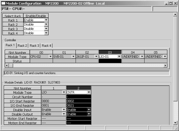
25 1.4 Module Configuration Definition Module Configuration Window Module Configuration Window Module Configuration Window has Controller area and Module Details area. Selecting the slot number in the Controller area, the details of the selected Module set in the relevant slot are displayed in the Module Details area. Fig. 1.4 MP2300/MP2300S Module Configuration Window Mounting Modules 1 Fig. 1.5 MP2100M/MP2200/MP2500MD Module Configuration Window 25

26 1.4 Module Configuration Definition Changing the Module Configuration Definition Changing the Module Configuration Definition ( 1 ) Module Details Function details can be set in the Module Details Area. efer to 2.3 IO-01/IO-02 Module Details on page 39 for information on setting IO-01/IO-02 Module details. efer to 3.3 IO-04/ IO-05 Module Details on page 75 for information on setting IO-04/IO-05 Module details. efer to 4.3 IO-06 Module Details on page 91 for information on setting IO-06 Module details. efer to 5.3 DO-01 Module Details on page 124 for information on setting DO-01 Module details. ( 2 ) Manual Allocation of I/O egisters I/O registers can be changed in the Module Details Area. Double-click the I/O leading register, input the desired value, and confirm the change. The I/O end register will be changed automatically when the I/O leading register is changed. After changing the register number, save the definition data by selecting File Save & Save into flash memory from the main menu. When changing a register number, make sure that the new register number is not already allocated. If a register number that is already allocated is used, the text will turn red. If this occurs, change the register number. 26
27 2 IO-01/IO-02 Module This chapter describes the IO-01/IO-02 Module in detail. 2.1 Outline of IO-01/IO-02 Modules Outline of Functions IO-01/IO-02 Module Appearance and Connector External Dimensions Specifications ED Indicators and Switch Settings Specifications of IO-01/IO-02 Module Connections Connector Specifications Cable Specifications Input Circuits Output Circuit Pulse Input Circuit IO-01/IO-02 Module Connections IO-01/IO-02 Module Details ocal I/O Configuration Counter Module Configuration Details of Counter Functions Pulse Counting Modes Pulse Count Function Coincidence Output and Coincidence Interrupt Functions PI atch Function Axis Type Selection Electronic Gear Function Outline Settings Electronic Gear Setting Examples Precautions When Using Electronic Gears IO-01/IO-02 Module 2 27
28 2.1 Outline of IO-01/IO-02 Modules Outline of Functions 2.1 Outline of IO-01/IO-02 Modules Outline of Functions The IO-01 and IO-02 Modules are I/O Modules having digital I/O and pulse counter functions. There are 16 digital inputs (DI) and 16 digital outputs (DO) (IO-01: sink mode outputs, IO-02: source mode outputs) for the digital I/O function. There is also 1 pulse input (PI) channel for the pulse counter function. Digital I/O and pulse input are made at a periodical cycle for each high-speed scan or low-speed scan of the MP2000 Series Machine Controller. The following diagram outlines the functions of the IO-01 and IO-02 Module. Interrupt input Input processing DI-00 DI points Input port (Isolated DI) System bus Pulse input processing Coincidence interrupt atch input Coincidence output DO-00 5-V/12-V Z input 5-V differential A/B input 16 points I/O connector Output processing Output port (Isolated DI) FUSE blown detection DO-00 to 15 Fig. 2.1 Outline of IO-01/IO-02 Module Functions IO-01/IO-02 Module Appearance and Connector External Dimensions The following figure shows the appearance of the IO-01/IO-02 Modules and their connector external dimensions. ED indicators 48 Switch IO-01 D1 D5 D2 D6 IO-02 D1 D5 D2 D6 D3 D7 D3 D7 D4 D8 D4 D8 MODE MODE 2 I/O connector I/O I/O Unit: mm IO-01 and IO-02 Modules have the same external dimensions for the connector. 28
29 2.1 Outline of IO-01/IO-02 Modules Specifications Specifications The following shows the specifications of the IO-01/IO-02 Modules. ( 1 ) Hardware Specifications Item Classification I/O Module Specifications Name IO-01 IO-02 Model JAPMC-IO2300 JAPMC-IO2301 Digital Input Digital Output 16 inputs 24 VDC, 4.1 ma, combined sink mode/source mode inputs (DI_00 also used for interrupts, DI-01 also used for pulse latch inputs) 16 outputs 24 VDC transistor open-collector outputs, sink mode outputs (DO_00 also used for coincidence outputs) Phase A/B/Z inputs Phase AB: 5-V differential input, not isolated, max. frequency: 4 MHz Pulse Input Phase Z: 5-V/12-V photocoupler input atch input Pulse latch for phase Z or DI_01. Connector I/O: I/O connector D1 (green) D2 (green) D3 (green) D4 (green) ED Indicators D5 (green) D6 (green) D7 (green) D8 (green) Switch otary switch (SW1) Current Consumption 500 ma max. Dimensions (mm) (H D) Mass 80 g 16 outputs 24 VDC transistor open-collector outputs, source mode outputs (DO_00 also used for coincidence outputs) IO-01/IO-02 Module 2 29
30 2.1 Outline of IO-01/IO-02 Modules Specifications ( 2 ) Environmental Conditions Environmental Conditions Mechanical Operating Conditions Item Specifications Ambient Operating Temperature 0 to 55 C Ambient Storage Temperature -25 to 85 C Ambient Operating Humidity 30% to 95% (with no condensation) Ambient Storage Humidity 5% to 95% (with no condensation) Pollution evel Pollution level 1 (conforming to JIS B 3501) Corrosive Gas There must be no combustible or corrosive gas. Operating Altitude 2,000 m above sea level or lower Conforming to JIS B 3502: 10 to 57 Hz with single-amplitude of mm Vibration esistance 57 to 150 Hz with fixed acceleration of 9.8 m/s 2 10 sweeps each in X, Y, and Z directions (sweep time: 1 octave/min) Shock esistance Conforming to JIS B 3502: Peak acceleration of 147 m/s 2 twice for 11 ms each in the X, Y, and Z directions Electrical Operating Conditions Noise esistance Conforming to EN , EN (Group 1, Class A) Power supply noise (FT noise): 2 kvmin., for one minute adiation noise (FT noise): 1 kvmin., for one minute Ground noise (impulse noise): 1 kvmin, for 10 minutes Electrostatic noise (contact discharge): 4 kvmin, for 10 times Installation equirements Ground Cooling Method Ground to 100 Ω max. Natural cooling 30
31 0 2.1 Outline of IO-01/IO-02 Modules ED Indicators and Switch Settings ED Indicators and Switch Settings D1 D2 D3 D4 D5 D6 D7 D The IO-01 and IO-02 Module status display ED indicators (D1 to D8) change based on the SW1 rotary switch settings (setting range: 0 to 5). The following table shows the indicator display for DI and DO status according to the SW1 setting. Indicators SW1 SW1 (otary Switch) Set Value 0 (Board Status Indicator) 1 (DI Input Indicator 1) 2 (DI Input Indicator 2) 3 (DO Output Indicator 1) 4 (DO Output Indicator 2) 5 (PI Input Indicator) D No. Status When it (Green) D No. Status When it (Green) D1 Normal (Error when not lit) D5 Normal (Error when not lit) D2 D3 D4 One of the inputs D1_00 to DI_07 is ON. One of the outputs DO_00 to DO_07 is ON. Pulse A/B input. The Phase A/B is ON. D6 D7 D8 One of the inputs DI_08 to DI_15 is ON. One of the outputs DO_08 to DO_15 is ON. Pulse Z input. The Phase Z is ON. D1 DI_00 is ON. D5 DI_04 is ON. D2 DI_01 is ON. D6 DI_05 is ON. D3 DI_02 is ON. D7 DI_06 is ON. D4 DI_03 is ON. D8 DI_07 is ON. D1 DI_08 is ON. D5 DI_12 is ON. D2 DI_09 is ON. D6 DI_13 is ON. D3 DI_10 is ON. D7 DI_14 is ON. D4 DI_11 is ON. D8 DI_15 is ON. D1 DO_00 is ON. D5 DO_04 is ON. D2 DO_01 is ON. D6 DO_05 is ON. D3 DO_02 is ON. D7 DO_06 is ON. D4 DO_03 is ON. D8 DO_07 is ON. D1 DO_08 is ON. D5 DO_12 is ON. D2 DO_09 is ON. D6 DO_13 is ON. D3 DO_10 is ON. D7 DO_14 is ON. D4 DO_11 is ON. D8 DO_15 is ON. D1 Pulse A input D5 Coincidence detection D2 Pulse B input D6 Phase-Z latch D3 Pulse Z input D7 DI latch D4 D8 IO-01/IO-02 Module 2 31
32 2.2 Specifications of IO-01/IO-02 Module Connections Connector Specifications 2.2 Specifications of IO-01/IO-02 Module Connections Connector Specifications The IO-01/IO-02 Module connector connects the external I/O signals or pulse input signal. (External input: 16 points, external output: 16 points, pulse input: 1 channel) The following tables provide the specifications of the IO-01/IO-02 Module connector. ( 1 ) Connector Model Name Connector Name No. of Pins I/O Connector I/O 48 FCN-365P048-AU ( 2 ) Connector Pin Arrangement Connector Model Module Side Cable Side Manufacturer FCN-360C048-E (cover), FCN-364J048-AU Fujitsu component The following table shows the connector pin arrangement for IO-01/IO-02 Modules viewed from the wiring side and the details of the pins. A1 B1 A24 B24 Pin No. Signal Name I/O emarks Pin No. Signal Name I/O emarks A1 PA I Phase-A pulse (+) B1 PA I Phase-A pulse ( ) A2 PB I Phase-B pulse (+) B2 PB I Phase-B pulse ( ) A3 PC I Phase-Z pulse (+) B3 PC5 I Phase-Z pulse ( 5-V input) A4 GND I Pulse input ground B4 PC12 I Phase-Z pulse ( 12-V input) A5 DO_COM P Output common B5 DO_COM P Output common A6 DO_24V P +24 V input B6 DO_24V P +24 V input A7 DO_15 O Output 15 B7 DO_14 O Output 14 A8 DO_13 O Output 13 B8 DO_12 O Output 12 A9 DO_11 O Output 11 B9 DO_10 O Output 10 A10 DO_09 O Output 9 B10 DO_08 O Output 8 A11 DO_07 O Output 7 B11 DO_06 O Output 6 A12 DO_05 O Output 5 B12 DO_04 O Output 4 A13 DO_03 O Output 3 B13 DO_02 O Output 2 A14 DO_01 O Output 1 B14 DO_00 O Output 0 A15 DI_15 I Input 15 B15 DI_14 I Input 14 A16 DI_13 I Input 13 B16 DI_12 I Input 12 A17 DI_11 I Input 11 B17 DI_10 I Input 10 A18 DI_09 I Input 9 B18 DI_08 I Input 8 A19 DI_07 I Input 7 B19 DI_06 I Input 6 A20 DI_05 I Input 5 B20 DI_04 I Input 4 A21 DI_03 I Input 3 B21 DI_02 I Input 2 A22 DI_01 I Input 1 B22 DI_00 I Input 0 A23 DI_COM0 P Input common 0 B23 DI_COM1 P Input common 1 A24 FG Frame ground B24 FG Frame ground P: Power supply input; I: Input signal; O: Output signal 32
33 2.2 Specifications of IO-01/IO-02 Module Connections Cable Specifications Cable Specifications The following shows the specifications of the IO-01/IO-02 Module standard cables. ( 1 ) Standard Cable Model ist Name Model ength External Appearance (JEPMC-W2061- ) JEPMC-W2061-A5 0.5 m Cable for IO-01/02 Modules JEPMC-W m (Single loose wire) JEPMC-W m ( 2 ) Standard Cable Wiring Table The wiring table for the standard cable JEPMC-W2061- is shown below. 48-pin Connector Terminal No. Marking Marking Wire Color Color Marking Color Marks 48-pin Connector Terminal No. A1 ed Orange Black B1 A2 ed Gray Black B2 A3 ed White Black B3 A4 ed Yellow Black B4 A5 ed Pink Black B5 A6 ed Orange Black B6 A7 ed Gray Black B7 A8 ed White Black B8 A9 ed Yellow Black B9 A10 ed Pink Black B10 A11 ed Orange Black B11 A12 ed Gray Black B12 A13 ed White Black B13 A14 ed Yellow Black B14 A15 ed Pink Black B15 A16 ed Orange Black B16 A17 ed Gray Black B17 A18 ed White Black B18 A19 ed Yellow Black B19 A20 ed Pink Black B20 A21 A22 A23 ed ed ed Continuous Continuous Continuous Orange Gray White Black Black Black Continuous Continuous Continuous A24 Shield B24 B21 B22 B23 IO-01/IO-02 Module 2 33
34 2.2 Specifications of IO-01/IO-02 Module Connections Input Circuits Input Circuits The following table shows the IO-01/IO-02 Module input circuit specifications. Item Specifications Inputs 16 points Input Format Sink mode/source mode input Isolation Method Photocoupler Input Voltage 24 VDC, ±20% (+19.2 to V) Input Current 4.1 ma (typ.) ON Voltage/Current 15 V min./2.0 ma min. OFF Voltage/Current 5 V max./1.0 ma max. ON Time/OFF Time ON: 0.5 ms max. OFF: 0.5 ms max. Number of Commons 2 (8 points/common) DI_00 is shared with an interrupt input. If DI_00 is turned ON while interrupts are Other Functions enabled, the interrupt processing drawing (program) is executed. DI_01 is shared with pulse latch inputs. If DI-01 is turned ON while pulse latch inputs are enabled, the pulse counter will be latched. +24V DI_COM Vcc Internal circuit DI_IN 5.6kΩ 0 24 Fig. 2.2 Digital Input Circuit (Sink Mode Input) Åj +24V DI_COM Vcc Internal circuit DI_IN 5.6kΩ 0 24 Fig. 2.3 Digital Input Circuit (Source Mode Input) 34
35 2.2 Specifications of IO-01/IO-02 Module Connections Output Circuit Output Circuit Outputs The following table shows the IO-01/IO-02 Module output circuit specifications. Item Output Format Isolation Method 16 points IO-01 IO-02 Photocoupler Output Voltage +24 VDC, ±20% Output Current eakage Current When OFF ON Time/OFF Time Number of Commons Protection Circuit Error Detection Other Functions 100 ma max. 0.1 ma max. Specifications Transistor, open collector sink mode output Transistor, open collector source mode output ON: 1 ms max. OFF: 1 ms max. 1 (16 points/common) Fuse The fuse is not, however, for circuit protection. It is for protecting against fire at output shorts. Attach a fuse externally to each output if circuit protection is required. Fuse blown detection eplace the Module when fuse blown is detected. DO_00 is shared with counter coincidence output. +24V Internal circuit DO_24V DO_OUT DO_COM 0 24 Fig. 2.4 IO-01 Digital Output Circuit (Sink Mode Output) +24V Internal circuit DO_24V DO_OUT IO-01/IO-02 Module DO_COM Fig. 2.5 IO-02 Digital Output Circuit (Source Mode Output) 35
36 2.2 Specifications of IO-01/IO-02 Module Connections Pulse Input Circuit Pulse Input Circuit The following table shows the IO-01/IO-02 Module pulse input circuit specifications. Item Number of Channels Input Circuit Input Mode atch Input Other Functions Specifications 1 channel (Phase-A/B/Z input) Phase-AB: 5-V differential input, not isolated, max. frequency: 4 MHz Phase-Z: 5-V/12-V photocoupler input Phase-A/B, signed, incremental/decremental Pulse latch on phase-z or DI_01. esponse time at phase-z input ON: 1 μs max. OFF: 1 μs max. esponse time at DI_01 input ON: 60 μs max. OFF: 0.5 ms max. Coincidence detection, counter preset A1 PA Phase A Pulse Generator +5V B1 PA 0V A2 PB Phase B B2 PB +5V A4 GND atch input or phase-z pulse A3 B3 B4 PC PC5 PC12 Fig. 2.6 Pulse Input Circuit 36
37 2.2 Specifications of IO-01/IO-02 Module Connections IO-01/IO-02 Module Connections IO-01/IO-02 Module Connections The following diagrams show connection examples for IO-01/IO-02 Module connectors. ( 1 ) IO-01 Module Connectors Pulse Generator Pulse input A1 B1 A2 B2 PA PA PB PB Phase A +5V 0V A4 GND atch input or phase-z pulse +5V A24 B24 A3 B3 B4 PC PC5 PC12 5V atch input or phase-z pulse Digital input A23 B22 A22 DI_COM0 DI_00 DI_01 24 VDC B21 DI_02 A21 B20 DI_03 DI_04 External input signals A20 DI_05 B19 DI_06 A19 DI_07 Digital input B23 B18 A18 DI_COM1 DI_08 DI_09 24 VDC B17 DI_10 A17 B16 DI_11 DI_12 External input signals A16 DI_13 B15 DI_14 A15 DI_15 B6 Digital output A6 B14 A14 DO_24V DO_00 DO_01 Fuse 24 VDC B13 A13 DO_02 DO_03 B12 DO_04 A12 DO_05 B11 A11 B10 A10 B9 A9 B8 A8 B7 A7 Fuse A5 B5 Fuse blown detection circuit DO_06 DO_07 DO_08 DO_09 DO_10 DO_11 DO_12 DO_13 DO_14 DO_15 DO_COM DO_COM External output signals IO-01/IO-02 Module 2 The pins No. A5 and B5, and the pins No. A6 and B6 are internally connected. Connect them externally as well. A fuse is inserted in the output common line of the IO-01 Module for circuit protection. However, the fuse may not be blown out in the cases such as layer shorts in outputs. To ensecure the circuit protection, provide a protective element such as fuse in each output as shown in the above diagram. 37
38 2.2 Specifications of IO-01/IO-02 Module Connections IO-01/IO-02 Module Connections ( 2 ) IO-02 Module Connectors Pulse generator A1 PA Phase A +5V Pulse input B1 A2 PA PB Phase B 0V B2 PB A4 GND atch input or phase-z pulse +5V A24 B24 A3 B3 B4 PC PC5 PC12 5V atch input or phase-z pulse Digital input A23 B22 A22 DI_COM0 DI_00 DI_01 24 VDC B21 DI_02 A21 B20 DI_03 DI_04 External input signals A20 DI_05 B19 DI_06 A19 DI_07 Digital input B23 B18 A18 DI_COM1 DI_08 DI_09 24 VDC B17 A17 B16 DI_10 DI_11 DI_12 External input signals A16 DI_13 B15 DI_14 A15 DI_15 Fuse blown detection circuit B6 DO_24V Digital output Fuse A6 B14 A14 DO_24V DO_15 DO_14 Fuse 24 VDC B13 A13 DO_13 DO_12 B12 A12 B11 DO_11 DO_10 DO_09 External output signals A11 DO_08 B10 DO_07 A10 DO_06 B9 A9 DO_05 DO_04 B8 DO_03 A8 B7 A7 DO_02 DO_01 DO_00 A5 DO_COM B5 DO_COM The pins No. A5 and B5, and the pins No. A6 and B6 are internally connected. Connect them externally as well. A fuse is inserted in the output common line of the IO-02 Module for circuit protection. However, the fuse may not be blown out in the cases such as layer shorts in outputs. To ensecure the circuit protection, provide a protective element such as fuse in each output as shown in the above diagram. 38

39 2.3 IO-01/IO-02 Module Details ocal I/O Configuration 2.3 IO-01/IO-02 Module Details IO-01/IO-02 Module details, such as the local I/O and Counter Module functions, can be set in the ocal I/O Window or the Counter Module Window. These window can be displayed from the Module Configuration Window ocal I/O Configuration ( 1 ) Displaying the ocal I/O Window Select IO-01 or IO-02 in the Module Type Column of the Controller Area of the Module Configuration Window. Double-click the cell with the IO in the Module Details Area. A confirmation box for creating a new file will be displayed. Click the OK Button. The ocal I/O Window will be displayed. efer to Displaying the Module Configuration Window on page 24 for information on displaying the Module Configuration Window. IO-01/IO-02 Module 2 39

40 2.3 IO-01/IO-02 Module Details ocal I/O Configuration ( 2 ) ocal I/O Configuration Details The following items are displayed in the ocal I/O Window. The discrete inputs, discrete outputs, and interrupt inputs can be set. D : Enable or disable each item by clicking on the cell. : Enabled, : Disabled The register length is fixed at one word, i.e., 16 points are set for each input or output register. EG : Displays the register number allocated to the inputs or outputs. It cannot be changed. Word : Displays the word size of the register data. It cannot be changed. SCAN : Select the speed from HIGH, OW, or NA (none specified), for the scan that processes the inputs or outputs. Current Value : The current value of the register will be displayed in binary when online. It will not be displayed when offline. The outputs to external devices can be set by changing the current value of the discrete outputs. When the set value is confirmed, it is immediately saved in the register. Other current values cannot be changed. HEX : The current value of the register will be displayed in hexadecimal when online. It will not be displayed when offline. After changing the local I/O configuration, save the definition data by selecting File Save & Save into flash memory from the main menu. 40

41 2.3 IO-01/IO-02 Module Details Counter Module Configuration Counter Module Configuration ( 1 ) Displaying the Counter Module Window Select IO-01 or IO-02 in the Module Type Column of the Controller Area of the Module Configuration Window. Double-click the cell with CNT in the Module Details Area. A confirmation box for creating a new file will be displayed. Click the OK Button. The Counter Module Window will be displayed. efer to Displaying the Module Configuration Window on page 24 for information on displaying the Module Configuration Window. If the counter function is not used with IO-01 nor IO-02, select UNDEFINED instead of CNT. IO-01/IO-02 Module 2 41


42 2.3 IO-01/IO-02 Module Details Counter Module Configuration ( 2 ) Counter Module Window In the Counter Module Window, there are two tab pages, Fix Parameter Set and I/O Data Set. Fixed parameters and I/O data can be set from these tab pages. Fig. 2.7 Counter Module Fix Parameter Set Tab Page Fig. 2.8 Counter Module I/O Data Set Tab Page 42
43 2.3 IO-01/IO-02 Module Details Counter Module Configuration ( 3 ) Setting the Fixed Parameters Set the following fixed parameters in the Fix Parameter Set tab page in the Counter Module Window. Counter Fixed Parameters No. Name Description Size Default SYNC-SCAN (Synchronous Scan Selection) The First egister Number (eading egister Number) A/B Pulse Signal Form Selection A/B Pulse Signal Polarity Selection *1 Pulse Counting Mode Selection *1 Select a scan cycle of the MP2000 Series Machine Controller to update the I/O data of counter function: High-speed scan or ow-speed scan. Displays the leading register number that corresponds to the parameter. This setting is disabled. Signal form of phases A and B. The signal form is fixed to a +5V differential input. Select either positive or negative logic for the signal polarity of phases A and B. Specify the pulse counting mode *1 among the following 7 equations. Pulse and Direction Pulse and Direction 2 Up/Down Counter Up/Down Counter 2 A/B Pulse A/B Pulse 2 A/B Pulse (Quadrature) 1 word 1 word High Fixed to +5V (differential input) 1 word Positive logic 1 word A/B Pulse (Quadrature) 04 Counter Mode Selection The counter mode is fixed to Up/Down Counter. 1 word Fixed to Up/Down Counter 05 Coincidence Detection Function Use Selection Set whether or not the coincidence detection *2 is to be used. 1 word Not use 06 Coincidence Interrupt Function Use Selection Set whether or not the coincidence interrupt function *2 is to be used. (Valid only when the coincidence detection function is set.) 1 word Not use 07 Axis Selection Set the axis type *3 : Finite or infinite length axis. 1 word Finite length axis 08 eference Unit Selection Specify the reference unit. pulse mm deg inch If pulse is selected, an electronic gear is not to be used; If a unit other than pulse is selected, an electronic gear is to be used. 1 word pulse Number of Digits Below Decimal Point Travel Distance per Set *4, *5 Machine otation Set the number of digits 0 to 5 below the decimal point *4 for the minimum reference unit. Example: If the minimum reference unit is 1 μm (10 3 mm): eference unit selection : mm, and Number of digits below decimal point: 3 the load moving amount per load axis rotation. Setting range: 1 to (reference unit) 11 Encoder Gear atio *4, *5 when the load axis rotates n times. Set the value m so that the encoder axis rotates m times Setting range: 1 to Machine Gear atio Set the value n so that the encoder axis rotates m times when *4, *5 the load axis rotates n times. (oad) Setting range: 1 to Maximum Value of otary Counter (Infinite ength Axis eset Position (POSMAX)) *3 If the Infinite ength Axis was selected for fixed parameter No.07, specify the number of rotations (1 to reference units) after which the axis will be reset. 1 word 3 2 words word 1 1 word 1 2 words IO-01/IO-02 Module 2 43
44 2.3 IO-01/IO-02 Module Details Counter Module Configuration (cont d) No. Name Description Size Default 14 Encoder esolution (Pre Quadrature) (Number of Pulses Per Encoder otation (before Multiplication)) Set the number of input pulses per encoder rotation. Setting range: 1 to (pulse/rev) * 1. For details, refer to Pulse Counting Modes on page 49. * 2. For details, refer to Coincidence Output and Coincidence Interrupt Functions on page 52. * 3. For details, refer to Axis Type Selection on page 54. * 4. For details, refer to 2.5 Electronic Gear Function on page 55. * 5. If pulse is selected for the parameter No. 08, parameters No. 10 to 12 are ignored. 2 words 2048 If SYNC-SCAN (Synchronous Scan Selection) or Scan Time Setting is changed, be sure to save the data in the flash memory and restart the controller. 44
![2.3 IO-01/IO-02 Module Details 2.3.2 Counter Module Configuration ( 4 ) I/O Data Settings [ a ] I/O Data Setting Tab Page Set the I/O data in the I/O Data Set Tab Page in the Counter Module Window.](/docs-images/83/88751206/images/45-0.jpg "The channel number is fixed to CH1. The details on the status and I/O data that can be monitored in the I/O Data Set Tab Page are described below.")
45 2.3 IO-01/IO-02 Module Details Counter Module Configuration ( 4 ) I/O Data Settings [ a ] I/O Data Setting Tab Page Set the I/O data in the I/O Data Set Tab Page in the Counter Module Window. The channel number is fixed to CH1. The details on the status and I/O data that can be monitored in the I/O Data Set Tab Page are described below. [ b ] In (Input) Data Details The following table provides details of the In Data Area. Abbreviated names are given in square brackets in the Name column. No. egister No. Name Contents ange Unit Size The run status of the Counter Module is indicated for each bit. When online: : ON ( = 1 ), : OFF ( = 0 ), IW 00 *1 Status (un Status) [UNSTS] When off line: Bit 0 Error Setting the Data (Data setting error) Bit 1 Fixed Parameter Error Bit 2 Preset Count Completed Bit 3 PI atch Completed Bit 4 A/B Pulse 0 (Feedback pulse is ±1 or less) Bit 5 Coincidence Detection Bit 6 A-Pulse Status Monitor Bit 7 B-Pulse Status Monitor Bit 9 Fixed Parameter Write Bit A A-Pulse Disconnection Bit B B-Pulse Disconnection POSMAX Preset Bit C (POSMAX turns presetting completed) Bit F Module eady 1 word IO-01/IO-02 Module 2 45
46 2.3 IO-01/IO-02 Module Details Counter Module Configuration No. egister No. 01 I 02 Incremental Pulses [PDV] Indicates the difference between the pulse count value at previous scan and that at present scan. 02 I 04 Counter Value [PFB] Indicates the pulse count value of each scan. 03 I I I 0A 06 I 0C 07 I 0E PI atch Value [FEQ] After Convert Increment Pulse [PDVG] Current Count Value After Converts [PFBG] PI atch Value After Converts [FEQG] Number of POSMAX Turns Indicates the current value of the counter when an external signal is input. Indicates the number of incremental pulses converted to a value in the reference unit. Indicates the same value as the number of incremental pulses if pulse is selected for the fixed parameter No. 08 eference Unit Selection (when the electronic gear is not used). Indicates the current value of the counter converted to a value in the reference unit. Indicates the same value as the counter current value when pulse is selected for the fixed parameter No. 08 eference Unit Selection (when the electronic gear is not used). Indicates the PI latch data converted to a value in the reference unit. Indicates the same value as the PI latch data when pulse is selected for the fixed parameter No. 08 eference Unit Selection (when the electronic gear is not used). Indicates the number of rotations that have been made when Infinite ength Axis is selected for the fixed parameter No. 07 Axis Selection. 08 I 10 Feedback Speed *2 If the electronic gear *3 is not used, the unit is pulse/s to to to to to to to to I 1E System Monitor For system use 2 words to * 1. IW 00 gives the register number that is displayed in The First egister Number cell on the Fix Parameter Set Tab Page * 2. The Feedback Speed is the moving average of the results of the following calculation for 32 scans. Without Electronic Gear (eference unit: Pulse) Feedback Speed (pulse/s) = No. of incremental pulses 1000)/Ts With Electronic Gear (eference unit: Unit other than pulse) Feedback Speed (reference unit/s) = No. of incremental pulses after conversion 1000)/Ts TS: Scan time (ms) for counter synchronized scan. * 3. efer to 2.5 Electronic Gear Function on page 55. pulse pulse pulse eference unit eference unit eference unit otation eference unit (cont d) Name Contents ange Unit Size 2 words 2 words 2 words 2 words 2 words 2 words 2 words 2 words 46
47 2.3 IO-01/IO-02 Module Details Counter Module Configuration [ c ] Out (Output) Data Details The following table shows details of the Out Data Area. Abbreviated names are given in square brackets in the Name column. No. egister No. OW 00 *1 OW O O O 06 Name Contents ange Unit Size Operation Mode (UN Mode) [UNMOD] Set Function/ atch Detection Signal Count Presetting Data [PSDAT] Agreed Detection Value (Coincidence Detection Set Value) [COINDAT] Preset Data of POSMAX Turns Count Disable ON (=1): Counting prohibited OFF (=0): Counting enabled Bit 0 (Default) Prohibits counting while the bit is ON (=1). Calculating Preset (Count Preset equest) ON (=1): equest preset Bit 1 OFF (=0): Not requested (Default) esets the count to its preset value when the bit is turned ON (=1). PI atch Detect Demand *2 ON (=1): equest latch detection OFF (=0): Not requested (Default) Bit 2 Stores the counter value at the moment an external signal is input while the bit is ON (=1). Coincidence Detection *3 ON (=1): equest coincidence detection OFF (=0): Not requested (Default) Bit 3 Sends a coincidence signal if the values of the counter and the coincidence detection setting match when the bit is turned ON (=1). POSMAX Presetting (POSMAX Turns Presetting equest) ON (=1): equests preset Bit 4 OFF (=0): Not requested (Default) esets the number of POSMAX turns to its preset value when the bit turns ON (=1). Select the external signal to be used for the PI latch signal. 0001H: DI latch (discrete input) 0002H: Z latch (phase-z input) The current value of the counter is reset to this value when a Count Preset equest is output. A coincidence detection signal and an interrupt signal to the MP2000 Series Machine Controller are output if the current value of the counter equals the value set in this parameter when the Coincidence Detection equest is output. The number of POSMAX turns is reset to the value set in this parameter when a POSMAX Turn Number Presetting equest is output. 0001H to 0002H to to to eference units eference units otations 04 O 1E System Monitor For system use. 1 word 1 word 2 words 2 words 2 words IO-01/IO-02 Module 2 * 1. OW 00 gives the register number that is displayed in The First egister Number cell on the Fix Parameter Set Tab Page * 2. efer to PI atch Function on page 53. * 3. efer to Coincidence Output and Coincidence Interrupt Functions on page
48 2.4 Details of Counter Functions 2.4 Details of Counter Functions For the counter function, the command is determined according to the settings of the counter fixed parameters and output registers, and the status and counter value are stored in input registers. The following diagram shows the data flow for the counter function. MP2000 Series Machine Controller IO-01 or IO-02 Module Virtual shared memory Input egisters (32 words) Information to MP2000 Series Machine Controller from IO-01 or IO-02 Module Commands from MP2000 Series Machine Controller to IO-01 or IO-02 Module Interrupt processing section Operation status Incremental pulse Current counter value atch data, etc. Output registers (32 words) Operation mode Counting preset data Coincidence detection setting, etc. Coincidence interrupt Pulse input processor 5-V differential interface Phase-Z 5-V/ 12-V voltage interface I/O connector Pulse input Counter Fixed Parameters Condition settings for counter function use atch input DI-01 Coincidence detection output DO-00 Pulse A/B signal polarity selection Pulse counting mode Other function selections In this section, the fixed parameters mean the counter fixed parameters if not otherwise mentioned. efer to 1.3 Self-configuration on page 21 to execute self-configuration of the Machine Controller before setting the fixed parameters. The following describes the details of pulse counting modes, pulse count function, coincidence output and coincidence interrupt functions, and PI latch function among the counter functions of the IO-01 or IO-02 Modules. 48
49 2.4 Details of Counter Functions Pulse Counting Modes Pulse Counting Modes The following pulse counting modes can be selected by setting the counter fixed parameter No. 3 (Pulse Counting Mode Selection) and No.2 A/B Pulse Signal Polarity Selection. Pulse Counting Mode Polarity Up Count (Forward) Down Count (everse) Positive logic Pulse Aパルス A Pulse Bパルス B OW Pulse AパルスA Pulse Bパルス B HIGH Pulse and Direction 1 Negative logic Positive logic Pulse Aパルス A Pulse Bパルス B Pulse Aパルス A Pulse Bパルス B HIGH OW Pulse AパルスA Pulse Bパルス B Pulse AパルスA Pulse BパルスB OW HIGH 2 Negative logic Pulse Aパルス A Pulse Bパルス B OW Pulse Aパルス A Pulse B Bパルス OW Positive logic Pulse Aパルス A Pulse BパルスB Fixed at low or high OWまたはHIGHに固定 Pulse Aパルス A Pulse Bパルス B Fixed OWまたは at low HIGH or に固定 high 1 UP/DOWN Counter 2 Negative logic Positive logic Negative logic Pulse Aパルス A Pulse Bパルス B OWまたはHIGHに固定 Fixed at low or high Pulse AパルスA Pulse Bパルス B Fixed OWまたは at low HIGH or に固定 high Pulse AパルスA Pulse Bパルス B Fixed OWまたは at low HIGH or に固定 high Pulse Aパルス A Fixed OWまたは at low HIGH or に固定 high Pulse Bパルス B Pulse Aパルス A Fixed OWまたは at low HIGH or に固定 high Pulse Bパルス B Pulse Aパルス A Fixed OWまたは at low HIGHor に固定 high Pulse Bパルス B A/B Pulse 1 2 Positive logic Negative logic Positive logic Negative logic Pulse Aパルス A Pulse Bパルス B Pulse Aパルス A Pulse Bパルス B Pulse AパルスA Pulse Bパルス B Pulse Aパルス A Pulse Bパルス B Pulse AパルスA Pulse Bパルス B Pulse AパルスA Pulse Bパルス B Pulse Aパルス A Pulse Bパルス B Pulse AパルスA Pulse Bパルス B IO-01/IO-02 Module 2 Positive logic Pulse Aパルス A Pulse Bパルス B Pulse AパルスA Pulse Bパルス B 4 Negative logic Pulse Aパルス A Pulse Bパルス B Pulse Aパルス A Pulse Bパルス B 49
50 2.4 Details of Counter Functions Pulse Count Function Pulse Count Function The Pulse Count Function reads A/B pulse input signals to increment (forward run) or decrement (reverse run) the count. The following graph shows changes in the pulse count for each run mode MAX p3 p6 Count preset (1) p2 p7 Counter count register value 0 n3 n2 p1 Cancel count prohibit p8 Count preset (2) n6 n1 Count prohibit n4 n5 n7 Count prohibit Cancel count prohibit MIN Time (s) p4 p5 Ts Current counter value display n1 n2 n3 n4 n5 n6 n7 Count preset data p2 p8 Ts Scan time (s) <Explanation> Current counter value The values of n1 to n7 (counter value at each scan) is displayed sequentially in Counter Value (I 04). Count preset (1) Executing the Count preset at the position p1 forces the counter value to change to the preset value (p2 value). MAX overflow When the counter value increases to the value MAX (p3), the counter value will be automatically reset to the value MIN (p4). MIN overflow When the counter value decreases to the value MIN (p5), the counter value will be automatically reset to the value MAX (p6). Count preset (2) Executing the Count preset at the position p7 forces the counter value to change to the preset value (p8 value). 50
51 2.4 Details of Counter Functions Pulse Count Function Count Preset Completion Timing The following diagram shows the count preset completion timing of the IO-01 or IO-02 Modules, which differs from the completion timing of the CNT-01 Module (Counter Module). (efer to Fig Count Preset Completion Timing of CNT-01 Module.) Calculating Preset (Count Preset equest) (OW 00 Bit 1) Count Preset equest: ON Count Preset Completed: ON Scan cycle Ts Preset Count Completed (IW 00 Bit 2) Count Preset m2 Counter count register value Current Count Value After Converts (I 0A) m1 m2 m1 m2 m3 m4 m3 Data that reflects count preset value m4 Fig. 2.9 Count Preset Completion Timing of IO-01 or IO-02 Module Calculating Preset (Count Preset equest) (OW 00 Bit 1) Count Preset equest: ON Count Preset Completed: ON Scan cycle Ts Preset Count Completed (IW 00 Bit 2) Count Preset m2 Counter count register value Current Count Value After Converts (I 0A) m1 m2 m1 m2 m3 m4 m3 m4 Data that reflects count preset value IO-01/IO-02 Module Fig Count Preset Completion Timing of CNT-01 Module 2 51
52 2.4 Details of Counter Functions Coincidence Output and Coincidence Interrupt Functions Coincidence Output and Coincidence Interrupt Functions The Coincidence Output and Coincidence Interrupt Functions output an external output signal (coincidence detection signal) and output an interrupt signal to the MP2000 Series Machine Controller when the current counter value and a preset output register value (Coincidence Detection Setting: O +4) match. The Coincidence Output equest is enabled when Use is set to the counter fixed parameter No. 5 (Coincidence Detection Function Use Selection). The Coincidence Interrupt equest is enabled if Use is set to the counter fixed parameter No. 6 (Coincidence Interrupt Function Use Selection). The following graph shows the number of occurrences from when coincidence detection request signal is output to when the coincidence point is detected and DWG.I (interrupt drawing) starts execution. Coincidence point Current counter value 0 Coincidence detection set value Time (s) Coincidence detection request signal Coincidence output signal Interrupt request signal DWG.I T Execute * T: Time when the coincidence point is detected to when DWG.I (interrupt drawing) starts execution (approx. 60 to 440 μs) DO-00 is used as a coincidence output signal. When the counter fixed parameter No. 05 (Coincidence Detection Function Use Selection) is set to Use, DO_00 will be masked. So, when setting a register, which is allocated to DO_00, using a ladder program to ON or OFF, the setting of this register will not be valid because the other setting has priority. To monitor the coincidence detection signal, use Coincidence Detection in the Status (un Status). Disable coincidence detection request when using the Count Preset. If the Count Preset is being used with the coincidence detection request enabled, coincidence point may be detected at the incorrect point because the matching point before the coordinate system has been rebuilt will be used. 52
53 2.4 Details of Counter Functions PI atch Function PI atch Function The PI latch function saves (latches) the current value to a memory register (I 06) on the rising edge of an external signal. Select either a discrete input (DI latch) or phase-z (Z latch) as the external signal. The following graph shows the number of occurrences from when PI latch signal is output to when the rising edge of an external signal is detected and PI latch data is displayed. External signal rising edge detected point Current counter value 0 PI latch data Hardware latch Time (s) PI latch detection request signal External input signal (either a discrete signal or phase Z) DI latch (discrete input): 60 μs or more *1 Phase C pulse (Phase-Z input): 1μs or more *2 PI latch completed signal PI latch register display PINT PI latch data * 1. When discrete input is changed from ON to OFF, the next ON signal cannot be received unless at least 500 μs passes after the change. * 2. When phase-z input is changed from ON to OFF, the next ON signal cannot be received unless at least 1 μs passes after the change. IO-01/IO-02 Module 2 53
54 2.4 Details of Counter Functions Axis Type Selection Axis Type Selection There are two types of axis: An infinite length axis that resets the current value with a specified value, and a finite length axis that does not reset the current value. The finite length axis is used for rotation in one direction only, where the current value data does not need to be reset after rotation, and for return and other operations are performed only within a specified range. The infinite length axis is used for applications such as resetting the current value data for a conveyor belt or other device to 0 after one rotation. The type of the axis to be used is selected by fixed parameter No. 07 (Axis Selection). If infinite length axis is set, the current counter value after conversion and the PI latch data after conversion is stored in the range 0 to infinite length axis reset position 1. Set the reset position in the counter fixed parameter No. 13 (Maximum Value of otary Counter) (Infinite ength Axis eset Position) (POSMAX). POSMAX 0 54
55 2.5 Electronic Gear Function Outline 2.5 Electronic Gear Function The Electronic Gear Function can be used when other than pulse is set to the counter fixed parameter No. 08 (eference Unit Selection) Outline The Electronic Gear Function is used to set the workpiece travel distance per pulse input to the IO Module counter to any value. The following example describes differences in operations to move a workpiece 10 mm using the equipment shown below with and without electronic gear function. When using the electronic gear function, simply input the reference value calculated for the travel distance regardless of the number of pulses to move a workpiece for a specified travel distance. No. of encoder pulses: 8192 Workpiece Ball screw pitch: 6 mm When the Electronic Gear is Not Used To move a workpiece 10 mm: 1 revolution is 6 mm. Therefore, 10 6 = revolutions pulses is 1 revolution. Therefore, = pulses pulses are input as reference pulses. The equation must be calculated at the host controller. When the Electronic Gear is Used To move a workpiece 10 mm: Mechanical conditions and minimum reference unit are defined with electronic gear. To move a workpiece 10 mm, the minimum reference unit is set to 1 μm. Therefore, 10 (mm) 1 (μm) = is input as reference value Settings Use steps 1 to 5 in the following procedure to make the settings. 1. Confirm the machine specifications. Elements relating to the Electronic Gear Gear ratio Ball screw pitch Pulley diameter, etc. Gear ratio Ball screw pitch 2. Check the number of encoder pulses displayed in Counter Value, and set this value to the counter fixed parameter No. 14 (Encoder esolution (Pre Quadrature)) (Number of Pulses Per Encoder otation). 3. Set the reference unit (the smallest reference unit for the reference data to move a load) according to the settings in the counter fixed parameters No. 08 (eference Unit Selection) and No. 09 (Number of Digits Below Decimal Point). eference to move a table in units of mm. eference unit: mm IO-01/IO-02 Module 2 Consider the machine specifications and positioning precision when setting the reference unit. 55
56 2.5 Electronic Gear Function Settings When reference unit is 1 μm: When 50,000 reference pulses are input, the workpiece will be moved by 50,000 1 μm = 50 mm. 4. Find the load travel distance for each rotation of the load axis using the reference unit and set this distance to the counter fixed parameter No. 10 (Travel Distance per Machine otation). oad travel distance per rotation of load axis (reference unit) = oad travel distance per load axis rotation eference unit EXAMPE Calculation Examples For a ball screw pitch of 5 mm and a reference unit of mm: = (eference unit) Ball screw otary table Belt + pulley oad axis P P: Pitch One P rotation = eference unit oad axis One rotation = 360 eference unit oad axis πd D D: Pulley diameter One = πd rotation eference unit 5. Set the Encoder Gear atio and the Machine Gear atio in the counter fixed parameters No. 11 and No.12. When the encoder axis has rotated m times and the mechanical configuration allows the load axis to rotate n times, set the following values: No. 11 (Encoder Gear atio) = m rotations No. 12 (Machine Gear atio) = n rotations Setting range: 1 to 65,535 [rotations] <Setting Example> For the configuration shown in the diagram: 4 rotations 4 回転 7 rotations 7 回転 エンコーダ軸 Encoder axis m rotations m 回転 oad 負荷軸 axis n 回転 rotations 9 rotations 9 回転 3 rotations 3 回転 Gear ratio = n/m = (3/7) (4/9) = 4/21 Therefore, set the following values: No.11 (Encoder Gear atio) = 4 (rotations) No.12 (Machine Gear atio) = 21 (rotations) 56
57 2.5 Electronic Gear Function Electronic Gear Setting Examples Electronic Gear Setting Examples The following is setting examples for each kind of load mechanical configuration. ( 1 ) Example A: Ball Screw Encoder m 7 rotations n 5 rotations Ball screw pitch P 6mm/rotation In the above machine system, if the reference unit = mm, the setting of each parameter will be as follows: Moving Amount Per Machine otation = 6 mm/0.001 mm = 6000 Counter fixed parameter No. 11 (Encoder Gear atio) = 7 (rotations) Counter fixed parameter No. 12 (Machine Gear atio) = 5 (rotations) ( 2 ) Example B: otating oad Encoder m 30 rotations n 10 rotations In the above machine system, if the reference unit = 0.1, the setting of each parameter will be as follows: Moving Amount Per Machine otation = 360 /0.1 = 3600 otating load 360 /rotation Counter fixed parameter No. 11 (Encoder Gear atio) = 3 (rotations) Counter fixed parameter No. 12 (Machine Gear atio) = 1 (rotation) IO-01/IO-02 Module 2 57
58 2.5 Electronic Gear Function Precautions When Using Electronic Gears Precautions When Using Electronic Gears When using electronic gears, make sure that the After Convert Incremental Pulse (Number of Incremental Pulses After Conversion) (I 08) is not outside the range for double integers ( to ). If it is outside this range, counter parameters after conversion, such as the After Convert Incremental Pulse (I 08), Current Count Value after Conversion (I 0A), and PI atch Value (I 0C), may not be correctly reported. Conditions to Fit within ange The following is the conditional expression for the After Convert Incremental Pulse (I 08) to fit within the range for double integers. Maximum frequency of input pulse (Hz) Ts * (ms) 1000(ms ) Workpiece travel distance per pulse (reference units/pulse) * Ts: Scan time setting The workpiece travel distance per pulse can be found using the following formula. Workpiece travel distance per pulse (reference units/pulse) = No.10 *1 Travel Distance Per Machine otation No.14 *1 Encoder esolution (Pre Quadrature) Multiplication *2 No.12 *1 Machine Gear atio No.11 *1 Encoder Gear atio * 1. No.10, No.11, No.12, and No.14 are fixed parameters. * 2. Multiplication value of fixed parameter No. 3, Pulse Counting Mode Selection. (For example, for A/B Pulse (Quadrature), the multiplication value is 4.) 58
59 3 IO-04/IO-05 Module This chapter describes the IO-04/IO-05 Module in detail. 3.1 Outline of IO-04/IO-05 Modules Outline of Functions IO-04/IO-05 Module Appearance and Connector External Dimensions Specifications ED Indicators Specifications of IO-04/IO-05 Module Connections Connector Specifications Cable Specifications Input Circuit Output Circuit IO-04 Module Connections IO-05 Module Connections IO-04/ IO-05 Module Details Displaying the ocal I/O Window ocal I/O Configuration Details IO-04/IO-05 Module 3 59
60 3.1 Outline of IO-04/IO-05 Modules Outline of Functions 3.1 Outline of IO-04/IO-05 Modules Outline of Functions The IO-04/IO-05 Module is equipped with the following digital I/O functions. IO-04: 32 digital inputs (DI) and 32 digital outputs (DO) (sink mode output) IO-05: 32 digital inputs (DI) and 32 digital outputs (DO) (source mode output) Digital I/O is made at a periodical cycle for each high-speed scan or low-speed scan of the MP2000 Series Machine Controller. The following diagram outlines the functions of the IO-04/IO-05 Module. Interrupt input Input processing DI-00 DI-01 Input port (Isolated DI) 16 points Output processing Output port (Isolated DO) 16 points CN1 System bus Fuse blown detection Interrupt input DO-00 to 07 DO-08 to 15 DI-16 DI points Input processing Input port (Isolated DI) Output processing Output port (Isolated DO) 16 points CN2 Fuse blown detection DO-16 to 23 DO-24 to 31 Fig. 3.1 Outline of IO-04/IO-05 Module Functions IO-04/IO-05 Module Appearance and Connector External Dimensions The following figure shows the appearance of the IO-04/IO-05 Modules and the connector external dimensions. ED Indicators 41 IO-04 IO-05 UN FU UN FU CN1 CN1 II/O connector II/O connector 2 CN2 CN Unit: mm IO-04 and IO-05 Modules have the same external dimensions for the connectors. 60
61 3.1 Outline of IO-04/IO-05 Modules Specifications Specifications The following shows the specifications of the IO-04/IO-05 Modules. ( 1 ) Hardware Specifications Item Classification I/O Module Specifications Name IO-04 IO-05 Model JAPMC-IO2303 JAPMC-IO2304 Digital Input 32 inputs 24 VDC±20% (+19.2V to +28.8V), 4.1 ma (TYP), combined sink mode/source mode inputs (DI-00, -01, -16, and -17 also used for interrupts) Number of simultaneously ON inputs: 16 (8/connector with 24 VDC), 10 (5/connector with 28.8 VDC) *For details, refer to ( 3 ). 32 outputs Digital Output 24 VDC±20% (+19.2V to +28.8V), 100 ma max., transistor outputs, sink mode outputs ED Indicators UN (green) FUSE (red) Connectors CN1: I/O connector CN2: I/O connector Current Consumption 500mA max. Dimensions (mm) (H D) Mass 80 g 32 outputs 24 VDC±20% (+19.2V to +28.8V), 100 ma max., transistor outputs, source mode outputs ( 2 ) Environmental Conditions Environmental Conditions Mechanical Operating Conditions Electrical Operating Conditions Item Specifications Ambient Operating 0 to 55 C Temperature Ambient Storage -25 to 85 C Temperature Ambient Operating 30% to 95% (with no condensation) Humidity Ambient Storage Humidity 5% to 95% (with no condensation) Pollution evel Pollution level 1 (conforming to JIS B 3501) Corrosive Gas There must be no combustible or corrosive gas. Operating Altitude 2,000 m above sea level or lower Conforming to JIS B 3502: 10 to 57 Hz with single-amplitude of mm Vibration esistance 57 to 150 Hz with fixed acceleration of 9.8 m/s 2 10 sweeps each in X, Y, and Z directions (sweep time: 1 octave/min) Conforming to JIS B 3502: Shock esistance Peak acceleration of 147 m/s 2 twice for 11 ms each in the X, Y, and Z directions Conforming to EN , EN (Group 1, Class A) Power supply noise (FT noise): 2 kv min., for one minute adiation noise (FT noise): 1 kv min., for one minute Noise esistance Ground noise (impulse noise): 1 kv min., for 10 minutes Electrostatic noise (contact discharge): 4 kvmin., for 10 times IO-04/IO-05 Module 3 Installation equirements Ground Cooling Method Ground to 100 Ω max. Natural cooling 61
62 3.1 Outline of IO-04/IO-05 Modules ED Indicators ( 3 ) Number of Simultaneously ON Inputs - Ambient Temperature Characteristics The following graph shows the number of inputs that can be simultaneously ON depending on the ambient temperature. (Number of inputs) (32 inputs at 28 (32 inputs at 41 (Input voltage: 24 VDC) (Input voltage: 28.8 VDC) Number of Simultaneously ON Inputs (16 inputs at 55 (10 inputs at ED Indicators Ambient Temperature The following table shows the IO-04/IO-05 Module status when each indicator lamp is lit or unlit. Indicator Color When it When Unlit UN FUSE UN Green Normal operation Error occurrence FUSE ed One or some of the output protection fuses is blown out. Output protection fuses are normal. 62
63 3.2 Specifications of IO-04/IO-05 Module Connections Connector Specifications 3.2 Specifications of IO-04/IO-05 Module Connections Connector Specifications The IO-04/IO-05 Module connector connects the external I/O signals. (External input: 32 points, external output: 32 points) The following tables provide the specifications of the IO-04/IO-05 Module connector. ( 1 ) Connector Model Name Connector Name No. of Pins Connector Model Module Side Cable Side Manufacturer External I/O Connector CN1/ CN A3P Connector VE Shell A0-008 (screw locking) or F0-008 (one-touch locking) Sumitomo 3M Corporation IO-04/IO-05 Module 3 63
64 3.2 Specifications of IO-04/IO-05 Module Connections Connector Specifications ( 2 ) IO-04 Module Connector Pin Arrangement The following table shows the IO-04 Module connector (CN1 and CN2) pin arrangement viewed from the wiring side and the details of the pins. CN1 Connector Pin Arrangement (Viewed from Wiring Side) DI_00 DI_04 DICOM_2 DI_10 DI_14 DO_00 DO_04 DO_10 +24V_2 DO_ DICOM_1 DI_02 DI_06 DI_08 DI_12 DO_02 +24V_1 DO_06 DO_08 DO_ DI_01 DI_05 DI_11 DI_15 DO_01 0V_1 DO_05 0V_1 DO_11 DO_ DI_03 DI_07 DI_09 DI_13 DO_03 DO_07 DO_09 0V_2 DO_13 0V_2 CN1 Connector Details Pin No. Signal Name I/O emarks Pin No. Signal Name I/O emarks 1 DICOM_1 P Input common DI_00 I Digital input 0 (shared with interrupt input) 27 DI_01 I Digital input 1 (shared with interrupt input) 3 DI_02 I Digital input 2 28 DI_03 I Digital input 3 4 DI_04 I Digital input 4 29 DI_05 I Digital input 5 5 DI_06 I Digital input 6 30 DI_07 I Digital input 7 6 DICOM_2 P Input common DI_08 I Digital input 8 32 DI_09 I Digital input 9 8 DI_10 I Digital input DI_11 I Digital input 11 9 DI_12 I Digital input DI_13 I Digital input DI_14 I Digital input DI_15 I Digital input DO_00 O Digital output 0 37 DO_01 O Digital output 1 13 DO_02 O Digital output 2 38 DO_03 O Digital output V_1 P Common ground V_1 P 24-V power supply DO_04 O Digital output 4 41 DO_05 O Digital output 5 17 DO_06 O Digital output 6 42 DO_07 O Digital output V_1 P Common ground 1 19 DO_08 O Digital output 8 44 DO_09 O Digital output 9 20 DO_10 O Digital output DO_11 O Digital output V_2 P Common ground V_2 P 24-V power supply DO_12 O Digital output DO_13 O Digital output DO_14 O Digital output DO_15 O Digital output V_2 P Common ground 2 P: Power supply input, I: Input signal, O: Output signal 64
65 3.2 Specifications of IO-04/IO-05 Module Connections Connector Specifications CN2 Connector Pin Arrangement (Viewed from Wiring Side) DI_16 DI_20 DICOM_4 DI_26 DI_30 DO_16 DO_20 DO_26 +24V_4 DO_ DICOM_3 DI_18 DI_22 DI_24 DI_28 DO_18 +24V_3 DO_22 DO_24 DO_ DI_17 DI_21 DI_27 DI_31 DO_17 0V_3 DO_21 0V_3 DO_27 DO_ DI_19 DI_23 DI_25 DI_29 DO_19 DO_23 DO_25 0V_4 DO_29 0V_4 CN2 Connector Details Pin No. Signal Name I/O emarks Pin No. Signal Name I/O emarks 1 DICOM_3 P Input common DI_16 I Digital input 16 (shared with interrupt input) 27 DI_17 I Digital input 17 (shared with interrupt input) 3 DI_18 I Digital input DI_19 I Digital input 19 4 DI_20 I Digital input DI_21 I Digital input 21 5 DI_22 I Digital input DI_23 I Digital input 23 6 DICOM_4 P Input common DI_24 I Digital input DI_25 I Digital input 25 8 DI_26 O Digital input DI_27 I Digital input 27 9 DI_28 O Digital input DI_29 I Digital input DI_30 O Digital input DI_31 I Digital input DO_16 O Digital output DO_17 O Digital output DO_18 O Digital output DO_19 O Digital output V_3 P Common ground V_3 P 24-V power supply DO_20 O Digital output DO_21 O Digital output DO_22 O Digital output DO_23 O Digital output V_3 P Common ground 3 19 DO_24 O Digital output DO_25 O Digital output DO_26 O Digital output DO_27 O Digital output V_4 P Common ground V_4 P 24-V power supply DO_28 O Digital output DO_29 O Digital output DO_30 O Digital output DO_31 O Digital output V_4 P Common ground 4 IO-04/IO-05 Module 3 P: Power supply input, I: Input signal, O: Output signal 65
66 3.2 Specifications of IO-04/IO-05 Module Connections Connector Specifications ( 3 ) IO-05 Module Connector Pin Arrangement The following table shows the IO-05 Module connector (CN1 and CN2) pin arrangement viewed from the wiring side and the details of the pins. CN1 Connector Pin Arrangement (Viewed from Wiring Side) DI_00 DI_04 DICOM_2 DI_10 DI_14 DO_00 DO_04 DO_10 +24V_2 DO_ DICOM_1 DI_02 DI_06 DI_08 DI_12 DO_02 +24V_1 DO_06 DO_08 DO_ DI_01 DI_05 DI_11 DI_15 DO_01 0V_1 DO_05 DO_11 +24V_2 DO_ DI_03 DI_07 DI_09 DI_13 DO_03 +24V_1 DO_07 DO_09 0V_2 DO_13 CN1 Connector Details Pin No. Signal Name I/O emarks Pin No. Signal Name I/O emarks 1 DICOM_1 P Input common DI_00 I Digital input 0 (shared with interrupt input) 27 DI_01 I Digital input 1 (shared with interrupt input) 3 DI_02 I Digital input 2 28 DI_03 I Digital input 3 4 DI_04 I Digital input 4 29 DI_05 I Digital input 5 5 DI_06 I Digital input 6 30 DI_07 I Digital input 7 6 DICOM_2 P Input common DI_08 I Digital input 8 32 DI_09 I Digital input 9 8 DI_10 I Digital input DI_11 I Digital input 11 9 DI_12 I Digital input DI_13 I Digital input DI_14 I Digital input DI_15 I Digital input DO_00 O Digital output 0 37 DO_01 O Digital output 1 13 DO_02 O Digital output 2 38 DO_03 O Digital output V_1 P 0-V power supply V_1 P Common 24 V_ V_1 P Common 24 V_1 16 DO_04 O Digital output 4 41 DO_05 O Digital output 5 17 DO_06 O Digital output 6 42 DO_07 O Digital output DO_08 O Digital output 8 44 DO_09 O Digital output 9 20 DO_10 O Digital output DO_11 O Digital output V_2 P 0-V power supply V_2 P Common 24 V_ V_2 P Common 24 V_1 23 DO_12 O Digital output DO_13 O Digital output DO_14 O Digital output DO_15 O Digital output P: Power supply input, I: Input signal, O: Output signal 66
67 3.2 Specifications of IO-04/IO-05 Module Connections Connector Specifications CN2 Connector Pin Arrangement (Viewed from Wiring Side) DI_16 DI_20 DICOM_4 DI_26 DI_30 DO_16 DO_20 DO_26 +24V_4 DO_ DICOM_3 DI_18 DI_22 DI_24 DI_28 DO_18 +24V_3 DO_22 DO_24 DO_ DI_17 DI_21 DI_27 DI_31 DO_17 0V_3 DO_21 DO_27 +24V_4 DO_ DI_19 DI_23 DI_25 DI_29 DO_19 +24V_3 DO_23 DO_25 0V_4 DO_29 CN2 Connector Details Pin No. Signal Name I/O emarks Pin No. Signal Name I/O emarks 1 DICOM_3 P Input common DI_16 I Digital input 16 (shared with interrupt input) 27 DI_17 I Digital input 17 (shared with interrupt input) 3 DI_18 I Digital input DI_19 I Digital input 19 4 DI_20 I Digital input DI_21 I Digital input 21 5 DI_22 I Digital input DI_23 I Digital input 23 6 DICOM_4 P Input common DI_24 I Digital input DI_25 I Digital input 25 8 DI_26 O Digital input DI_27 I Digital input 27 9 DI_28 O Digital input DI_29 I Digital input DI_30 O Digital input DI_31 I Digital input DO_16 O Digital output DO_17 O Digital output DO_18 O Digital output DO_19 O Digital output V_3 P 0-V power supply V_3 P Common 24 V_ V_3 P Common 24 V_3 16 DO_20 O Digital output DO_21 O Digital output DO_22 O Digital output DO_23 O Digital output DO_24 O Digital output DO_25 O Digital output DO_26 O Digital output DO_27 O Digital output V_4 P 0-V power supply_ V_4 P Common 24 V_ V_4 P Common 24 V_4 23 DO_28 O Digital output DO_29 O Digital output DO_30 O Digital output DO_31 O Digital output IO-04/IO-05 Module 3 P: Power supply input, I: Input signal, O: Output signal 67
68 3.2 Specifications of IO-04/IO-05 Module Connections Cable Specifications Cable Specifications The following shows the specifications of the IO-04/IO-05 Module standard cables. ( 1 ) Standard Cable Model ist Name Model ength External Appearance (JEPMC-W6060- ) Cable for IO-4/ IO-05 Modules (Single loose wire) JEPMC-W JEPMC-W JEPMC-W m 1 m 3 m 50-core oose wires ( 2 ) Standard Cable Wiring Table The wiring table for the standard cable JEPMC-W6060- is shown below. 50-pin Connector Terminal No. Marking Wire Color Marking 50-pin Connector Terminal No. 1 Orange 26 2 Gray 27 3 White 28 4 Yellow 29 5 Pink 30 6 Orange 31 7 Gray 32 8 White 33 9 Yellow Pink Orange Gray White Yellow Pink Orange Continuous Gray Continuous White Continuous Yellow Continuous Pink Continuous Continuous Orange Continuous Gray Continuous White Continuous Yellow Continuous Pink 50 68
69 3.2 Specifications of IO-04/IO-05 Module Connections Input Circuit Input Circuit The following table shows the IO-04/IO-05 Module input circuit specifications. Inputs Item Input Format Isolation Method 32 points Sink mode/source mode input Photocoupler Input Voltage 24 VDC±20% (+19.2 to V) Input Current ON Voltage/Current OFF Voltage/Current ON Time/OFF Time Number of Commons Other Functions 4.1 ma (typ.) 15 V min./2.0 ma min. 5 V min./1.0 ma min. Specifications ON: 0.5 ms max. OFF: 0.5 ms max. 4 (8 points/common) DI_00 is shared with an interrupt input. If DI_00 is turned ON while interrupts are enabled, the interrupt processing drawing (program) is executed. DI_01, DI_16, and DI_17 are the same as DI_ V DICOM Vcc Internal circuit DI_IN 5.6kΩ 0 24 Fig. 3.2 Digital Input Circuit (Sink Mode Input) +24V DICOM Vcc Internal circuit DI_IN 5.6kΩ 0 24 Fig. 3.3 Digital Input Circuit (Source Mode Input) IO-04/IO-05 Module 3 69
70 3.2 Specifications of IO-04/IO-05 Module Connections Output Circuit Output Circuit The following table shows the IO-04/IO-05 Module output circuit specifications. Item Specifications Outputs 32 points Output Format IO-04 Transistor, sink mode output IO-05 Transistor, source mode output Isolation Method Photocoupler Output Voltage 24 VDC±20% (+19.2 to V) Output Current 100 ma max. eakage Current When OFF 0.1 ma max. ON Time/OFF Time ON: 0.5 ms max. OFF: 1 ms max. Number of Commons 4 (8 points/common) Fuse Protection Circuit The fuse is not, however, for circuit protection. It is for protecting against fire at output shorts. Attach a fuse externally to each output if circuit protection is required. Fuse ating 1 A Error Detection Fuse blown detection eplace the Module when the fuse blown is detected. +24V Internal circuit +24 V DO_OUT 0 V 0 24 Fig. 3.4 IO-04 Digital Output Circuit (Sink Mode Output) +24V +24 V Internal circuit DO_OUT 0 V 0 24 Fig. 3.5 IO-05 Digital Output Circuit (Source Mode Output) 70
71 Internal circuit 3.2 Specifications of IO-04/IO-05 Module Connections IO-04 Module Connections IO-04 Module Connections The following diagrams show connection examples for CN1/CN2 connector of the IO-04 Module. ( 1 ) CN1 Connector JAPMC-IO CN1 connector pin No. Common V Photocoupler Input 0 Input k Input 6 5 Input VDC Common 2 6 Photocoupler VDC + - Input 8 Input 9 Input 14 Input Output 1 Output 2 Output 3 Output 4 Output 5 Output 6 Output 7 Photocoupler Fuse blown detection circuit VDC + - Fuse blown detection circuit Output 8 Output 9 Output 10 Output 11 Output 12 Output 13 Output 14 Output 15 IO-04/IO-05 Module 3 The pins No. 39 and 43 and the pins No. 46 and 50 are internally connected. Connect them externally as well. A fuse is inserted in the output common line of the IO-04 Module for circuit protection. However, the fuse may not be blown out in the cases such as layer shorts in outputs. To ensecure the circuit protection, provide a protective element such as fuse in each output as shown in the above diagram. 71
72 Internal circuit 3.2 Specifications of IO-04/IO-05 Module Connections IO-04 Module Connections ( 2 ) CN2 Connector JAPMC-IO VDC Common 3 CN2 connector pin No. 1 +5V Photocoupler Input 16 Input 17 Input 22 Input k 24 VDC Common 4 6 Photocoupler VDC + - Input 24 Input 25 Input 30 Input Output 16 Output 17 Output 18 Output 19 Output 20 Output 21 Output 22 Output 23 Photocoupler Fuse blown detection circuit VDC Output 24 Output 25 Output 26 Output 27 Output 28 Output 29 Output 30 Output 31 Fuse blown detection circuit 46 The pins No. 39 and 43 and the pins No. 46 and 50 are internally connected. Connect them externally as well. A fuse is inserted in the output common line of the IO-04 Module for circuit protection. However, the fuse may not be blown out in the cases such as layer shorts in outputs. To ensecure the circuit protection, provide a protective element such as fuse in each output as shown in the above diagram. 72
73 3.2 Specifications of IO-04/IO-05 Module Connections IO-05 Module Connections IO-05 Module Connections The following diagrams show connection examples for CN1/CN2 connector of the IO-05 Module. ( 1 ) CN1 Connector JAPMC-IO VDC + - CN1 connector Common pin No V Photocoupler 24 VDC Input 0 Input 1 Input 6 Input 7 Common 2 Input 8 Input 9 Input 14 Input k Photocoupler Internal circuit Fuse blown detection circuit VDC Output 0 Output 1 Output 2 Output 3 16 Output Output 5 Output 6 Output 7 39 Fuse blown detection circuit 24 VDC Photocoupler 19 Output 8 44 Output 9 20 Output Output Output Output Output Output Check the polarity of the external power supply when wiring. An adverse connection may cause a load malfunction. The pins No. 15 and 40 and the pins No. 22 and 47 are internally connected. Connect them externally as well. IO-04/IO-05 Module 3 A fuse is inserted in the output common line of the IO-05 Module for circuit protection. However, the fuse may not be blown out in the cases such as layer shorts in outputs. To ensecure the circuit protection, provide a protective element such as fuse in each output as shown in the above diagram. 73
74 Internal circuit 3.2 Specifications of IO-04/IO-05 Module Connections IO-05 Module Connections ( 2 ) CN2 Connector JAPMC-IO VDC + - CN2 connector Common 3 pin No Photocoupler +5V Input 16 Input 17 Input k Input VDC Common 4 6 Fuse blown detection circuit 24 VDC Input 24 7 Photocoupler Input 25 Input 30 Input Output 16 Output 17 Output 18 Output Output 20 Output 21 Output 22 Output 23 Fuse blown detection circuit 24 VDC Photocoupler Output 24 Output 25 Output 26 Output 27 Output 28 Output 29 Output 30 Output 31 Check the polarity of the external power supply when wiring. An adverse connection may cause a load malfunction. The pins No. 15 and 40 and the pins 22 and 47 are internally connected. Connect them externally as well. A fuse is inserted in the output common line of the IO-05 Module for circuit protection. However, the fuse may not be blown out in the cases such as layer shorts in outputs. To ensecure the circuit protection, provide a protective element such as fuse in each output as shown in the above diagram. 74

75 3.3 IO-04/ IO-05 Module Details Displaying the ocal I/O Window 3.3 IO-04/ IO-05 Module Details IO-04/IO-05 Module details, such as the local I/O, can be set in the ocal I/O Window or the Counter Module Window. These windows can be displayed from the Module Configuration Window Displaying the ocal I/O Window Select IO-04 or IO-05 in the Module Type Column of the Controller Area of the Module Configuration Window. Double-click the cell with the IO in the Module Details Area. A confirmation box for creating a new file will be displayed. Click the OK Button. The ocal I/O Window will be displayed. efer to Displaying the Module Configuration Window on page 24 for information on displaying the Module Configuration Window. IO-04/IO-05 Module 3 75

76 3.3 IO-04/ IO-05 Module Details ocal I/O Configuration Details ocal I/O Configuration Details The following items are displayed in the ocal I/O Window. The discrete inputs, discrete outputs, and interrupt inputs can be set. D : Enable or disable each item by clicking on the cell. : Enabled, : Disabled The register length is fixed at one word, i.e., 16 points are set for each input or output register. EG : Displays the register number allocated to the inputs or outputs. It cannot be changed. Word : Displays the word size of the register data. It cannot be changed. SCAN : Select the speed from HIGH, OW, or NA (none specified), for the scan that processes the inputs or outputs. Current Value : The current value of the register will be displayed in binary when online. It will not be displayed when offline. The outputs to external devices can be set by changing the current value of the discrete outputs. When the set value is confirmed, it is immediately saved in the register. Other current values cannot be changed. HEX : The current value of the register will be displayed in hexadecimal when online. It will not be displayed when offline. After changing the local I/O configuration, save the definition data by selecting File Save & Save into flash memory from the main menu. 76
77 4 IO-06 Module This chapter describes the IO-06 Module in detail. 4.1 Outline of IO-06 Module Outline of Functions IO-06 Module Appearance and Connector External Dimensions Specifications ED Indicators Analog I/O Characteristics Specifications of IO-06 Module Connections Connector Specifications Cable Specifications Digital Input Circuits Digital Output Circuit Analog Input Circuit Analog Output Circuit Pulse Input Circuit IO-06 Module Connections Wiring for Noise Control IO-06 Module Details MIXIO Configuration Setting the I/O Offset/Gain Counter Module Configuration Details of Counter Functions Pulse Counting Modes Pulse Count Function Coincidence Output and Coincidence Interrupt Functions PI atch Function Axis Type Selection Electronic Gear Function Outline Settings Electronic Gear Setting Examples Precautions When Using Electronic Gears IO-06 Module 4 77
78 4.1 Outline of IO-06 Module Outline of Functions 4.1 Outline of IO-06 Module Outline of Functions The IO-06 Module is I/O Modules having digital I/O, analog I/O, and pulse counter functions. There are 8 digital inputs (DI) and 8 digital outputs (DO) (sink mode outputs) for the digital I/O function, and 1 analog input (AI) channel and 1 analog output (AO) channel for the analog I/O function. There is also 1 pulse input (PI) channel for the pulse counter function. Digital I/O, analog I/O, and pulse input are made at a periodical cycle for each high-speed scan or low-speed scan of the MP2000 Series Machine Controller. The following diagram outlines the functions of the IO-06 Module. Interrupt input Input processing DI-00 DI-01 Input port (Isolated DI) 8 points System bus Pulse input processing Coincidence interrupt Output processing atch input Coincidence output DO-07 5-V/12-V/24-V Z input 5-V differential A/B input Output port (Isolated DO) 8 points I/O connector FUSE blown detection DO-00 to 07 Analog input processing Analog output processing Fig. 4.1 Outline of IO-06 Module Functions IO-06 Module Appearance and Connector External Dimensions The following figure shows the appearance of the IO-06 Module and the connector external dimensions. ED indicators IO-06 UN AM 41 CN1 125 I/O connector Unit mm 78
79 4.1 Outline of IO-06 Module Specifications Specifications The following shows the specifications of the IO-06 Module. ( 1 ) Hardware Specifications Item Classification Name Model I/O Module IO-06 JAPMC-IO2305-E Specifications 8 inputs Digital Input 24 VDC, 4.1 ma, combined sink mode/source mode inputs (DI_00 also used for interrupts, DI-01 also used for pulse latch inputs) 8 outputs Digital Output 24 VDC transistor open-collector outputs, sink mode outputs (DI_07 also used for coincidence outputs) 1 channel Analog Input Analog input range: -10 to +10 V esolution: 16 bits ( to ) 1 channel Analog Output Analog output range: -10 to +10 V esolution: 16 bits ( to ) Phase A/B/Z inputs Phase AB: 5-V differential input, not isolated, max. frequency: 4 MHz Pulse Input Phase Z: 5-V/12-V/24-V photocoupler input atch input Pulse latch for phase Z or DI_01. Connector I/O: I/O connector UN (green) ED Indicators AM (red) Current Consumption 800 ma max. Dimensions (mm) (H D) Mass 80 g IO-06 Module 4 79
80 4.1 Outline of IO-06 Module ED Indicators ( 2 ) Environmental Conditions Environmental Conditions Mechanical Operating Conditions Item Specifications Ambient Operating Temperature 0 to 50 C Ambient Storage Temperature -25 to 85 C Ambient Operating Humidity 30% to 95% (with no condensation) Ambient Storage Humidity 5% to 95% (with no condensation) Pollution evel Pollution level 1 (conforming to JIS B 3501) Corrosive Gas There must be no combustible or corrosive gas. Operating Altitude 2,000 m above sea level or lower Conforming to JIS B 3502: 10 to 57 Hz with single-amplitude of mm Vibration esistance 57 to 150 Hz with fixed acceleration of 9.8 m/s 2 10 sweeps each in X, Y, and Z directions (sweep time: 1 octave/min) Shock esistance Conforming to JIS B 3502: Peak acceleration of 147 m/s 2 twice for 11 ms each in the X, Y, and Z directions Electrical Operating Conditions Noise esistance Conforming to EN , EN (Group 1, Class A) Power supply noise (FT noise): 2 kvmin., for one minute adiation noise (FT noise): 1 kvmin., for one minute Ground noise (impulse noise): 1 kvmin, for 10 minutes Electrostatic noise (contact discharge): 4 kvmin, for 10 times Installation equirements ED Indicators Ground Cooling Method Ground to 100 Ω max. Natural cooling The following table shows the IO-06 Module status when each indicator lamp is lit or unlit. Indicator Color When it When Unlit UN Green Normal operation Operation stopped UN AM AM ed Error occurrence (ights when one of the following errors occurs) Blown fuse ASIC error for counter/ao Oscillator error Phases A and B disconnection Normal operation 80
81 4.1 Outline of IO-06 Module Analog I/O Characteristics Analog I/O Characteristics The analog I/O characteristics of the IO-06 Module and the voltage characteristics are described below. ( 1 ) Analog Input Characteristics Input Characteristics Table Analog Input Value Input egister Value V V V V V V V Voltage Input Characteristics Input register value inearity effective range: ±10.0 V V -10 V 0 0 V Analog input value 10 V 10.5 V ( 2 ) Analog Output Characteristics Output Characteristics Table Analog Output Value Output egister Value V V V V V V V Voltage Output Characteristics Output register value inearity effective range: ±10.0 V V -10 V 0 0 V Analog output value 10 V 10.5 V IO-06 Module
82 4.2 Specifications of IO-06 Module Connections Connector Specifications 4.2 Specifications of IO-06 Module Connections Connector Specifications The IO-06 Module connector connects the external I/O signals (digital/analog) or pulse input signal. (External digital input: 8 points, external digital output: 8 points, analog input: 1 channel, analog output: 1 channel, pulse input: 1 channel) The following tables provide the specifications of the IO-06 Module connector. ( 1 ) Connector Model Name Connector Name No of Pins Connector Model Module Side Cable Side Manufacturer External I/O Connector CN A3P (Conforming to ohs) Connector VE Shell A0-008 (Screw locking), or F0-008 (One-touch locking) Sumitomo 3M Corporation ( 2 ) IO-06 Module Connector Pin Arrangement The following table shows the IO-06 Module connector (CN1) pin arrangement viewed from the wiring side and the details of the pins. CN1 Connector Pin Arrangement (Viewed from Wiring Side) AI PA+ GND PIC24V DI_00 DI_04 DO_24V DO_02 DO_ AI_GND PB+ GND PI DI_01 DI_05 DO_24V DO_03 DO_ AO PA- PIC5V DICOM DI_02 DI_06 DO_00 DO_04 DO_GND AO_GND PB- PIC12V DICOM DI_03 DI_07 DO_01 DO_05 DO_GND 82
83 4.2 Specifications of IO-06 Module Connections Connector Specifications CN1 Connector Details Pin No. Signal Name I/O emarks Pin No. Signal Name I/O emarks 1 AO O Analog output 26 AO_GND O Analog output ground 2 AI I Analog input 27 AI_GND I Analog input ground PA+ I Phase-A pulse (+) 29 PB+ I Phase-B pulse (+) 5 PA- I Phase-A pulse (-) 30 PB- I Phase-B pulse (-) 6 GND I Pulse input ground 31 GND I Pulse input ground PIC5V P Phase-Z latch input common (5 V) 34 PIC12V P 10 PIC24V P Phase-Z latch input common (24 V) Phase-Z latch input common (12 V) 35 PI I Phase-Z latch input 13 DICOM P Digital input common 38 DICOM P Digital input common 14 DI_00 I Digital input 0 (shared with DI interrupt) 39 DI_01 I Digital input 1 (shared with DI latch input) 15 DI_02 I Digital input 2 40 DI_03 I Digital input 3 16 DI_04 I Digital input 4 41 DI_05 I Digital input 5 17 DI_06 I Digital input 6 42 DI_07 I Digital input DO_24V P DO power supply 24 V 45 DO_24V P DO power supply 24 V 21 DO_00 O Digital output 0 46 DO_01 O Digital output 1 22 DO_02 O Digital output 2 47 DO_03 O Digital output 3 23 DO_04 O Digital output 4 48 DO_05 O Digital output 5 24 DO_06 O Digital output 6 49 DO_07 O Digital output 7 25 DO_GND P DO common ground 50 DO_GND P DO common ground P: Power supply input; I: Input signal; O: Output signal Shell Shield wire IO-06 Module 4 83
84 4.2 Specifications of IO-06 Module Connections Cable Specifications Cable Specifications The following shows the specifications of the IO-06 Module standard cables. ( 1 ) Standard Cable Model ist Name Model ength External Appearance (JEPMC-W E) Cable for IO-06 Module (Single loose wire) JEPMC-W2064-A5-E JEPMC-W E JEPMC-W E 0.5 m 1 m 3 m 50-core oose wires Shield wire ( 2 ) Standard Cable Wiring Table The wiring table for the standard cable JEPMC-W E is shown below. 50-pin Connector Terminal No. Marking Wire Color Marking 50-pin Connector Terminal No. 1 Orange 26 2 Gray 27 3 White 28 4 Yellow 29 5 Pink 30 6 Orange 31 7 Gray 32 8 White 33 9 Yellow Pink Orange Gray White Yellow Pink Orange Continuous Gray Continuous White Continuous Yellow Continuous Pink Continuous Continuous Orange Continuous Gray Continuous White Continuous Yellow Continuous Pink 50 Shield wire Shell 84
85 4.2 Specifications of IO-06 Module Connections Digital Input Circuits Digital Input Circuits The following table shows the IO-06 Module digital input circuit specifications. Inputs Item Input Format Isolation Method 8 points Sink mode/source mode input Photocoupler Input Voltage 24 VDC, +10/ 20% (+19.2 to V) Input Current ON Voltage/Current OFF Voltage/Current ON Time/OFF Time Number of Commons Other Functions 4.1 ma (typ.) 15 V min./2.0 ma min. 5 V max./1.0 ma max. Specifications ON: 0.5 ms max. OFF: 0.5 ms max. 1 (8 points/common) DI_00 is shared with an interrupt input. If DI_00 is turned ON while interrupts are enabled, the interrupt processing drawing (program) is executed. DI_01 is shared with pulse latch inputs. If DI-01 is turned ON while pulse latch inputs are enabled, the pulse counter will be latched. +24V DI_COM Vcc Internal circuit DI_IN 5.6kΩ 0 24 Fig. 4.2 Digital Input Circuit (Sink Mode Input) Åj +24V DI_COM Vcc Internal circuit DI_IN 5.6kΩ 0 24 Fig. 4.3 Digital Input Circuit (Source Mode Input) IO-06 Module 4 85
86 4.2 Specifications of IO-06 Module Connections Digital Output Circuit Digital Output Circuit The following table shows the IO-06 Module digital output circuit specifications. Item Specifications Outputs 8 points Output Format Transistor, open collector sink mode output Isolation Method Photocoupler Output Voltage +24 VDC, ±20% Output Current 100 ma max. eakage Current When OFF 0.1 ma max. ON Time/OFF Time ON: 0.25 ms max. OFF: 1 ms max. Number of Commons 1 (8 points/common) Fuse Protection Circuit The fuse is not, however, for circuit protection. It is for protecting against fire at output shorts. Attach a fuse externally to each output if circuit protection is required. Error Detection Fuse blown detection eplace the Module when fuse blown is detected. Other Functions DO_07 is shared with counter coincidence output. +24V Internal circuit DO_24V DO_OUT DO_COM 0 24 Fig. 4.4 Digital Output Circuit (Sink Mode Output) 86
87 4.2 Specifications of IO-06 Module Connections Analog Input Circuit Analog Input Circuit The following table shows the IO-06 Module analog input circuit specifications. Item Number of Channels 1 channel Isolation Method Non-isolated Analog Input ange -10 to +10 V Max. ated Input ±15 V Input Impedance Approx. 20 kω esolution 16 bits ( to ) Accuracy 25 C ±0.1% (±10 mv) 0 to 50 C ±0.3% (±30 mv) Input Conversion Time * 1.05 ms max. Specifications * Input conversion time = Delay time from input filter (1 ms max.) + 50 μs; Delay time from the input filter peaks at 1 ms between -10 and +10 V Analog Output Circuit The following table shows the IO-06 Module analog output circuit specifications. Item Number of Channels Isolation Method Analog Output ange Output Impedance 1 channel Non-isolated -10 to +10 V 20 kω max. esolution 16 bits ( to ) Accuracy Max. Allowable oad Current 25 C ±0.1% (±10 mv) 0 to 50 C ±0.3% (±30 mv) ±5 ma Specifications Output Delay Time 1.2 ms (after change with a full scale of -10 to +10 V) IO-06 Module 4 87
88 4.2 Specifications of IO-06 Module Connections Pulse Input Circuit Pulse Input Circuit The following table shows the IO-06 Module pulse input circuit specifications. Item Number of Channels Input Circuit Input Mode atch Input Other Functions Specifications 1 channel (Phase-A/B/Z input) Phase-AB: 5-V differential input, not isolated, max. frequency: 4 MHz Phase-Z: 5-V/12-V/24-V photocoupler input Phase-A/B, signed, incremental/decremental Pulse latch on phase-z or DI_01. esponse time at phase-z input ON: 1 μs max. OFF: 1 μs max. (2 μs max. at 24-V input) esponse time at DI_01 input ON: 60 μs max. OFF: 0.5 ms max. Coincidence detection, counter preset 4 PA+ Phase A Pulse Generator +5V 5 PA- 0V 29 PB+ Phase B +5V 30 PB- 0V 6 GND 13 GND 10 PIC(24V) +5V 34 PIC(12V) 9 PIC(5V) atch input or phase-z pulse 35 PI Fig. 4.5 Pulse Input Circuit 88
89 4.2 Specifications of IO-06 Module Connections IO-06 Module Connections IO-06 Module Connections The following diagram shows connection example for IO-06 Module connectors. IO-06 Junction-terminal block +15V Analog output -15V 1 AO 26 AO_GND External Device -10 to V FG External Device Analog input -15V 2 AI 27 AI_GND V -10 to -10 FG Pulse Generator 4 5 PA+ PA- +5V Pulse input PB+ PB- 6 GND 31 GND 0V 10 PIC 24V 34 PIC 12V FG Phase Z latch input 9 PIC 5V 35 PI atch input +5V Digital input 13 DICOM 38 DICOM 14 DI_00 39 DI_01 15 DI_02 40 DI_03 16 DI_04 41 DI_05 17 DI_06 42 DI_07 External input signals Digital output Fuse blown detection circuit FG (connector shell) 20 DO_24V 45 DO_24V 21 DO_00 46 DO_01 22 DO_02 47 DO_03 23 DO_04 48 DO_05 24 DO_06 49 DO_07 25 DO_GND 50 DO_GND External input signals IO-06 Module 4 89
90 4.2 Specifications of IO-06 Module Connections Wiring for Noise Control Ground the cable shield between the external devices and the junction-terminal block on the external-device end. A fuse is inserted in the output common line of the IO-06 Module for circuit protection. However, the fuse may not be blown out in the cases such as layer shorts in outputs. To ensecure the circuit protection, provide a protective element such as fuse in each output as shown in the above diagram. 5 V, 12 V, and 24 V are available for phase-z input voltage. Note that the pin that is used will differ, depending on the input voltage. Using the wrong pin may cause an accident. At 5 V input: Use No.9 pin. At 12 V input: Use No.34 pin. At 24 V input: Use No.10 pin Wiring for Noise Control When the IO-06 Module is mounted and used in an environment where there is high-frequency noise from an external device, the counter may not correctly execute counting. In this case, install a noise filter or a ferrite core to suppress the high-frequency noise. The following figure shows an example of installing a noise filter and ferrite cores. MP2000 Series Machine Controller IO-06 External device Power supply Noise filter Terminal block Ferrite core Ferrite core ecommended Parts Name Model Manufacturer Ferrite core E04S Seiwa Electric MFG. Co. td. Noise filter F-210N NEC TOKIN Corporation 90

91 4.3 IO-06 Module Details MIXIO Configuration 4.3 IO-06 Module Details IO-06 Module details, such as the MIXIO, I/O offset gain, and Counter Module functions, can be set in the MIXIO Window or the Counter Module Window. These window can be displayed from the Module Configuration Window MIXIO Configuration ( 1 ) Displaying the MIXIO Window Select IO-06 in the Module Type Column of the Controller Area of the Module Configuration Window. Doubleclick the cell with the MIXIO in the Module Details Area. A confirmation box for creating a new file will be displayed. Click the OK Button. The MIXIO Window will be displayed. efer to Displaying the Module Configuration Window on page 24 for information on displaying the Module Configuration Window. IO-06 Module 4 91

92 4.3 IO-06 Module Details MIXIO Configuration ( 2 ) MIXO Configuration Details The following items are displayed in the MIXIO Window. The discrete inputs/outputs, interrupt inputs, and analog inputs/outputs can be set. D : Enable or disable each item by clicking on the cell. : Enabled, : Disabled EG : Displays the register number allocated to the inputs or outputs. It cannot be changed. Word : Displays the word size of the register data. It cannot be changed. The register length of discrete inputs/outputs is fixed at one word; 16 points are set for each input or output register, and 8 points of the input or output register are allocated to the lower bytes. The register length of the analog inputs/outputs is fixed at one word. SCAN : Select the speed from HIGH, OW, or NA (none specified), for the scan that processes the inputs or outputs. Current : The current value of the register will be displayed in binary when online. It will not be displayed (Current Value) when offline. The outputs to external devices can be set by changing the current value of the discrete outputs. When the set value is confirmed, it is immediately saved in the register. Other current values cannot be changed. HEX : The current value of the register will be displayed in hexadecimal when online. It will not be displayed when offline. Unit : Displays the unit [V] of the analog input/output current value For the range of to analog input value, [V] is displayed in the Unit. However, when the input value is out of this range, [V Above] is displayed and the Current (Current Value) will be fixed to or <Example> Analog Input Value Current Value Unit V [V] V [V] V [V Above] V [V] V [V] V [V Above] DATA : Displays the analog input/output register value with parentheses. <Example> Analog Input egister Value DATA IW = [12345] IW = [-12345] After changing the MIXIO configuration, save the definition data by selecting File Save & Save into flash memory from the main menu. 92
93 4.3 IO-06 Module Details Setting the I/O Offset/Gain Setting the I/O Offset/Gain The I/O offset/gain settings do not usually have to be adjusted. The IO-06 Module has been adjusted before shipment so the appropriate input/output value is input for the specified voltage or current. If more precise adjustments are required, use the following procedure to adjust the offset/gain. ( 1 ) Input Offset/Gain 1. After selecting Analog Input in the MIXIO Window, select Set - Offset/Gain. The Set Offset/Gain Dialog Box will be displayed. 2. The voltage of the external device can be set to 0 V, 5 V, or 10 V. After changing the voltage, the Current (Current Value) displayed for the Analog Input will also change. Adjust the offset/gain accordingly so they are in accordance with the Current (Current Value) displayed for the Analog Input. Then click the OK Button. 3. Save the offset/gain value to the MIXIO Window by selecting File - Save & Save into flash memory from the main menu. The offset/gain adapted value will be stored in the offset/gain input register (I register): Input register = A/D conversion value (data obtained from IO-06 Module) Gain + Offset The default values of the offset and gain are as follows: Offset: 0000 Gain: If using the default values, the Input register value equals the A/D conversion value. ( 2 ) Output Offset/Gain 1. Set the output register (O register) to 0 (0 V), and measure the output voltage (Output voltage 1). 2. Calculate the offset of the output voltage using the following equation. Offset value = Output voltage 1 ( ) (round off below decimal point) IO-06 Module 4 93
, and measure the output voltage (Output Voltage 2). 6. Calculate the gain of the output voltage using the following equation.")
94 4.3 IO-06 Module Details Setting the I/O Offset/Gain 3. After selecting Analog Output in the MIXIO Window, select Set - Offset/Gain. The Set Offset/Gain Dialog Box will be displayed. 4. Enter the calculated value at step 2 in the Offset Box of the Set Offset/Gain Dialog Box, and then click the OK Button. 5. Set the output register to (10 V), and measure the output voltage (Output Voltage 2). 6. Calculate the gain of the output voltage using the following equation. If the Output Voltage 2 is less than 10 volts, Gain = 10.0 Output Voltage 2 (ound to three decimal places.) If the Output Voltage 2 is greater than 10 volts, gradually reduce the value of the output register from until the output voltage 10 V. The value of the output register if the output voltage is approximately 10 V is EG1. Gain = EG (ound to three decimals places.) 7. Select Set - Offset/Gain from the main menu to display the Set Offset/Gain Dialog Box. Enter the calculated value at step 6 in the Offset Box of the Set Offset/Gain Dialog Box, and then click the OK Button. 8. Save the offset/gain value to the MIXIO Window by selecting File - Save & Save into flash memory from the main menu. The offset/gain adapted value will be stored in the offset/gain output register (O register): Output register = (Output voltage - Offset) Gain The default values of the offset and gain are as follows: Offset: 0000 (1 = 0.32 mv) Gain:

95 4.3 IO-06 Module Details Counter Module Configuration Counter Module Configuration ( 1 ) Displaying the Counter Module Window Select IO-06 in the Module Type Column of the Controller Area of the Module Configuration Window. Doubleclick the cell with CNT-A in the Module Details Area. A confirmation box for creating a new file will be displayed. Click the OK Button. The Counter Module Window will be displayed. efer to Displaying the Module Configuration Window on page 24 for information on displaying the Module Configuration Window. If the counter function is not used with IO-06, select UNDEFINED instead of CNT-A. IO-06 Module 4 95

96 4.3 IO-06 Module Details ( 2 ) Counter Module Window In the Counter Module Window, there are two tab pages, Fix Parameter Set and I/O Data Set. Fixed parameters and I/O data can be set from these tab pages. Fig. 4.6 Counter Module Fix Parameter Set Tab Page Fig. 4.7 Counter Module I/O Data Set Tab Page 96
97 4.3 IO-06 Module Details Counter Module Configuration ( 3 ) Setting the Fixed Parameters Set the following fixed parameters in the Fix Parameter Set tab page in the Counter Module Window. Counter Fixed Parameters No. Name Description Size Default SYNC-SCAN (Synchronous Scan Selection) The First egister Number (eading egister Number) A/B Pulse Signal Form Selection A/B Pulse Signal Polarity Selection *1 Pulse Counting Mode Selection *1 Select a scan cycle of the MP2000 Series Machine Controller to update the I/O data of counter function: High-speed scan or ow-speed scan. Displays the leading register number that corresponds to the parameter. This setting is disabled. Signal form of phases A and B. The signal form is fixed to a +5V differential input. Select either positive or negative logic for the signal polarity of phases A and B. Specify the pulse counting mode *1 among the following 7 equations. Pulse and Direction Pulse and Direction 2 Up/Down Counter Up/Down Counter 2 A/B Pulse A/B Pulse 2 A/B Pulse (Quadrature) 1 word 1 word High Fixed to +5V (differential input) 1 word Positive logic 1 word A/B Pulse (Quadrature) 04 Counter Mode Selection The counter mode is fixed to Up/Down Counter. 1 word Fixed to Up/Down Counter 05 Coincidence Detection Function Use Selection Set whether or not the coincidence detection *2 is to be used. 1 word Not use 06 Coincidence Interrupt Function Use Selection Set whether or not the coincidence interrupt function *2 is to be used. (Valid only when the coincidence detection function is set.) 1 word Not use 07 Axis Selection Set the axis type *3 : Finite or infinite length axis. 1 word Finite length axis 08 eference Unit Selection Specify the reference unit. pulse mm deg inch If pulse is selected, an electronic gear is not to be used; If a unit other than pulse is selected, an electronic gear is to be used. 1 word pulse Number of Digits Below Decimal Point Travel Distance per Set Machine otation *4, *5 Set the number of digits 0 to 5 below the decimal point *4 for the minimum reference unit. Example: If the minimum reference unit is 1 μm (10 3 mm): eference unit selection : mm, and Number of digits below decimal point: 3 the load moving amount per load axis rotation. Setting range: 1 to (reference unit) 11 Encoder Gear atio *4, *5 when the load axis rotates n times. Set the value m so that the encoder axis rotates m times Setting range: 1 to Machine Gear atio Set the value n so that the encoder axis rotates m times when (oad) *4, *5 the load axis rotates n times. Setting range: 1 to Maximum Value of otary Counter (Infinite ength Axis eset Position (POSMAX)) *3 If the Infinite ength Axis was selected for fixed parameter No.07, specify the number of rotations (1 to reference units) after which the axis will be reset. 1 word 3 2 words word 1 1 word 1 2 words IO-06 Module 4 97
98 4.3 IO-06 Module Details Counter Module Configuration (cont d) No. Name Description Size Default Encoder esolution (Pre Quadrature) (Number of Pulses Per Encoder otation (before Multiplication)) Detection of A/B-pulse Disconnection Set the number of input pulses per encoder rotation. Setting range: 1 to (pulse/rev) Select whether or not the phase A/B disconnection detection is enabled or not. * 1. For details, refer to Pulse Counting Modes on page 103. * 2. For details, refer to Coincidence Output and Coincidence Interrupt Functions on page 106. * 3. For details, refer to Axis Type Selection on page 108. * 4. For details, refer to 4.5 Electronic Gear Function on page 109. * 5. If pulse is selected for the parameter No. 08, parameters No. 10 to 12 are ignored. 2 words word disable If SYNC-SCAN (Synchronous Scan Selection) is changed, be sure to save the data in the flash memory and restart the controller. ( 4 ) I/O Data Settings [ a ] I/O Data Setting Tab Page Set the I/O data in the I/O Data Set Tab Page in the Counter Module Window. The channel number is fixed to CH1. The details on the status and I/O data that can be monitored in the I/O Data Set Tab Page are described below. 98
99 4.3 IO-06 Module Details Counter Module Configuration [ b ] In (Input) Data Details The following table provides details of the In Data Area. Abbreviated names are given in square brackets in the Name column. No. egister No. Name Contents ange Unit Size The run status of the Counter Module is indicated for each bit. When online: : ON ( = 1 ), : OFF ( = 0 ), IW 00 *1 01 I 02 Status (un Status) [UNSTS] Incremental Pulses [PDV] When off line: Bit 0 Error Setting the Data (Data setting error) Bit 1 Fixed Parameter Error Bit 2 Preset Count Completed Bit 3 PI atch Completed Bit 4 A/B Pulse 0 (Feedback pulse is ±1 or less) Bit 5 Coincidence Detection Bit 6 A-Pulse Status Monitor Bit 7 B-Pulse Status Monitor Bit 9 Fixed Parameter Write Bit A A-Pulse Disconnection Bit B B-Pulse Disconnection POSMAX Preset Bit C (POSMAX turns presetting completed) Bit F Module eady Indicates the difference between the pulse count value at previous scan and that at present scan. 02 I 04 Counter Value [PFB] Indicates the pulse count value of each scan. 03 I I I 0A 06 I 0C 07 I 0E PI atch Value [FEQ] After Convert Increment Pulse [PDVG] Current Count Value After Converts [PFBG] PI atch Value After Converts [FEQG] Number of POSMAX Turns Indicates the current value of the counter when an external signal is input. Indicates the number of incremental pulses converted to a value in the reference unit. Indicates the same value as the number of incremental pulses if pulse is selected for the fixed parameter No. 08 eference Unit Selection (when the electronic gear is not used). Indicates the current value of the counter converted to a value in the reference unit. Indicates the same value as the counter current value when pulse is selected for the fixed parameter No. 08 eference Unit Selection (when the electronic gear is not used). Indicates the PI latch data converted to a value in the reference unit. Indicates the same value as the PI latch data when pulse is selected for the fixed parameter No. 08 eference Unit Selection (when the electronic gear is not used). Indicates the number of rotations that have been made when Infinite ength Axis is selected for the fixed parameter No. 07 Axis Selection to to to to to to to pulse pulse pulse eference unit eference unit eference unit otation 1 word 2 words 2 words 2 words 2 words 2 words 2 words 2 words IO-06 Module 4 99
100 4.3 IO-06 Module Details Counter Module Configuration No. egister No. 08 I 10 Feedback Speed *2 If the electronic gear *3 is not used, the unit is pulse/s to I 1E System Monitor For system use 2 words to * 1. IW 00 gives the register number that is displayed in The First egister Number cell on the Fix Parameter Set Tab Page * 2. The Feedback Speed is the moving average of the results of the following calculation for 32 scans. Without Electronic Gear (eference unit: Pulse) Feedback Speed (pulse/s) = No. of incremental pulses 1000)/Ts With Electronic Gear (eference unit: Unit other than pulse) Feedback Speed (reference unit/s) = No. of incremental pulses after conversion 1000)/Ts TS: Scan time (ms) for counter synchronized scan. * 3. efer to 4.5 Electronic Gear Function on page 109. eference unit (cont d) Name Contents ange Unit Size 2 words 100
101 4.3 IO-06 Module Details Counter Module Configuration [ c ] Out (Output) Data Details The following table shows details of the Out Data Area. Abbreviated names are given in square brackets in the Name column. No. egister No. OW 00 *1 OW O O O 06 Name Contents ange Unit Size Operation Mode (UN Mode) [UNMOD] Set Function/ atch Detection Signal Count Presetting Data [PSDAT] Agreed Detection Value (Coincidence Detection Set Value) [COINDAT] Preset Data of POSMAX Turns Count Disable ON (=1): Counting prohibited OFF (=0): Counting enabled Bit 0 (Default) Prohibits counting while the bit is ON (=1). Calculating Preset (Count Preset equest) ON (=1): equest preset Bit 1 OFF (=0): Not requested (Default) esets the count to its preset value when the bit is turned ON (=1). PI atch Detect Demand *2 ON (=1): equest latch detection OFF (=0): Not requested (Default) Bit 2 Stores the counter value at the moment an external signal is input while the bit is ON (=1). Coincidence Detection *3 ON (=1): equest coincidence detection OFF (=0): Not requested (Default) Bit 3 Sends a coincidence signal if the values of the counter and the coincidence detection setting match when the bit is turned ON (=1). POSMAX Presetting (POSMAX Turns Presetting equest) ON (=1): equests preset Bit 4 OFF (=0): Not requested (Default) esets the number of POSMAX turns to its preset value when the bit turns ON (=1). Select the external signal to be used for the PI latch signal. 0001H: DI latch (discrete input) 0002H: Z latch (phase-z input) The current value of the counter is reset to this value when a Count Preset equest is output. A coincidence detection signal and an interrupt signal to the MP2000 Series Machine Controller are output if the current value of the counter equals the value set in this parameter when the Coincidence Detection equest is output. The number of POSMAX turns is reset to the value set in this parameter when a POSMAX Turn Number Presetting equest is output. 0001H to 0002H to to to eference units eference units otations 04 O 1E System Monitor For system use. 1 word 1 word 2 words 2 words 2 words IO-06 Module * 1. OW 00 gives the register number that is displayed in The First egister Number cell on the Fix Parameter Set Tab Page * 2. efer to PI atch Function on page 107. * 3. efer to Coincidence Output and Coincidence Interrupt Functions on page
102 4.4 Details of Counter Functions Counter Module Configuration 4.4 Details of Counter Functions For the counter function, the command is determined according to the settings of the counter fixed parameters and output registers, and the status and counter value are stored in input registers. The following diagram shows the data flow for the counter function. MP2000 Series Machine Controller IO-06 Module Virtual shared memory Input egisters (32 words) Information to MP2000 Series Machine Controller from IO-06 Module Commands from MP2000 Series Machine Controller to IO-06 Module Interrupt processing section Operation status Incremental pulse Current counter value atch data, etc. Output registers (32 words) Operation mode Counting preset data Coincidence detection setting, etc. Coincidence interrupt Pulse input processor 5-V differential interface Phase-Z 5-V/ 12-V/24-V voltage interface I/O connector Pulse input Counter Fixed Parameters Condition settings for counter function use atch input DI-01 Coincidence detection output DO-07 Pulse A/B signal polarity selection Pulse counting mode Other function selections In this section, the fixed parameters mean the counter fixed parameters if not otherwise mentioned. efer to 1.3 Self-configuration on page 21 to execute self-configuration of the Machine Controller before setting the fixed parameters. The following describes the details of pulse counting modes, pulse count function, coincidence output and coincidence interrupt functions, and PI latch function among the counter function of the IO-06 Modules. 102
103 4.4 Details of Counter Functions Pulse Counting Modes Pulse Counting Modes The following pulse counting modes can be selected by setting the counter fixed parameter No. 3 (Pulse Counting Mode Selection) and No.2 A/B Pulse Signal Polarity Selection. Pulse Counting Mode Polarity Up Count (Forward) Down Count (everse) Pulse and Direction* 1 2 Positive logic Negative logic Positive logic Negative logic Pulse Aパルス A Pulse Bパルス B Pulse Aパルス A Pulse Bパルス B Pulse Aパルス A Pulse Bパルス B Pulse Aパルス A Pulse Bパルス B OW HIGH OW OW Pulse AパルスA Pulse Bパルス B Pulse AパルスA Pulse Bパルス B Pulse AパルスA Pulse BパルスB Pulse Aパルス A Pulse B Bパルス HIGH OW HIGH OW UP/DOWN Counter 1 2 Positive logic Negative logic Positive logic Negative logic Pulse Aパルス A Pulse BパルスB Fixed at low or high OWまたはHIGHに固定 Pulse Aパルス A Pulse Bパルス B OWまたはHIGHに固定 Fixed at low or high Pulse AパルスA Pulse Bパルス B Fixed OWまたは at low HIGH or に固定 high Pulse AパルスA Pulse Bパルス B Fixed OWまたは at low HIGH or に固定 high Pulse Aパルス A Fixed OWまたは at low HIGH or に固定 high Pulse BパルスB Pulse Aパルス A Fixed OWまたは at low HIGH or に固定 high Pulse Bパルス B Pulse Aパルス A Fixed OWまたは at low HIGH or に固定 high Pulse Bパルス B Pulse Aパルス A Fixed OWまたは at low HIGHor に固定 high Pulse Bパルス B 1 Positive logic Negative logic Pulse Aパルス A Pulse Bパルス B Pulse Aパルス A Pulse Bパルス B Pulse A Pulse B Pulse A Pulse B A/B Pulse 2 Positive logic Negative logic Pulse AパルスA Pulse Bパルス B Pulse Aパルス A Pulse Bパルス B Pulse Aパルス A Pulse Bパルス B Pulse AパルスA Pulse Bパルス B 4 Positive logic Negative logic Pulse Aパルス A Pulse Bパルス B Pulse Aパルス A Pulse Bパルス B * In pulse and direction mode, input pulse A while sign (pulse B) is fixed. Pulse AパルスA Pulse Bパルス B Pulse Aパルス A Pulse Bパルス B IO-06 Module 4 103
104 4.4 Details of Counter Functions Pulse Count Function Pulse Count Function The Pulse Count Function reads A/B pulse input signals to increment (forward run) or decrement (reverse run) the count. The following graph shows changes in the pulse count for each run mode MAX p3 p6 Count preset (1) p2 p7 Counter count register value 0 n3 n2 p1 Cancel count prohibit p8 Count preset (2) n6 n1 Count prohibit n4 n5 n7 Count prohibit Cancel count prohibit MIN Time (s) p4 p5 Ts Current counter value display n1 n2 n3 n4 n5 n6 n7 Count preset data p2 p8 Ts Scan time (s) <Explanation> Current counter value The values of n1 to n7 (counter value at each scan) is displayed sequentially in Counter Value (I 04). Count preset (1) Executing the Count preset at the position p1 forces the counter value to change to the preset value (p2 value). MAX overflow When the counter value increases to the value MAX (p3), the counter value will be automatically reset to the value MIN (p4). MIN overflow When the counter value decreases to the value MIN (p5), the counter value will be automatically reset to the value MAX (p6). Count preset (2) Executing the Count preset at the position p7 forces the counter value to change to the preset value (p8 value). 104
105 4.4 Details of Counter Functions Pulse Count Function Count Preset Completion Timing The following diagram shows the count preset completion timing of the IO-06 Modules, which differs from the completion timing of the CNT-01 Module (Counter Module). (efer to Fig. 4.9 Count Preset Completion Timing of CNT-01 Module.) Calculating Preset (Count Preset equest) (OW 00 Bit 1) Count Preset equest: ON Count Preset Completed: ON Scan cycle Ts Preset Count Completed (IW 00 Bit 2) Count Preset m2 Counter count register value Current Count Value After Converts (I 0A) m1 m2 m1 m2 m3 m4 m3 Data that reflects count preset value m4 Fig. 4.8 Count Preset Completion Timing of IO-06 Module Calculating Preset (Count Preset equest) (OW 00 Bit 1) Count Preset equest: ON Count Preset Completed: ON Scan cycle Ts Preset Count Completed (IW 00 Bit 2) Count Preset m2 Counter count register value Current Count Value After Converts (I 0A) m1 m4 m2 m3 m1 m2 m3 m4 Data that reflects count preset value Fig. 4.9 Count Preset Completion Timing of CNT-01 Module IO-06 Module 4 105
106 4.4 Details of Counter Functions Coincidence Output and Coincidence Interrupt Functions Coincidence Output and Coincidence Interrupt Functions The Coincidence Output and Coincidence Interrupt Functions output an external output signal (coincidence detection signal) and output an interrupt signal to the MP2000 Series Machine Controller when the current counter value and a preset output register value (Coincidence Detection Setting: O +4) match. The Coincidence Output equest is enabled when Use is set to the counter fixed parameter No. 5 (Coincidence Detection Function Use Selection). The Coincidence Interrupt equest is enabled if Use is set to the counter fixed parameter No. 6 (Coincidence Interrupt Function Use Selection). The following graph shows the number of occurrences from when coincidence detection request signal is output to when the coincidence point is detected and DWG.I (interrupt drawing) starts execution. Coincidence point Current counter value 0 Coincidence detection set value Time (s) Coincidence detection request signal Coincidence output signal Interrupt request signal DWG.I T Execute * T: Time when the coincidence point is detected to when DWG.I (interrupt drawing) starts execution (approx. 60 to 440 μs) DO-07 is used as a coincidence output signal. When the counter fixed parameter No. 05 (Coincidence Detection Function Use Selection) is set to Use, DO_07 will be masked. So, when setting a register, which is allocated to DO_07, using a ladder program to ON or OFF, the setting of this register will not be valid because the other setting has priority. To monitor the coincidence detection signal, use Coincidence Detection in the Status (un Status). Disable coincidence detection request when using the Count Preset. If the Count Preset is being used with the coincidence detection request enabled, coincidence point may be detected at the incorrect point because the matching point before the coordinate system has been rebuilt will be used. 106
107 4.4 Details of Counter Functions PI atch Function PI atch Function The PI latch function saves (latches) the current value to a memory register (I 06) on the rising edge of an external signal. Select either a discrete input (DI latch) or phase-z (Z latch) as the external signal. The following graph shows the number of occurrences from when PI latch signal is output to when the rising edge of an external signal is detected and PI latch data is displayed. External signal rising edge detected point Current counter value 0 PI latch data Hardware latch Time (s) PI latch detection request signal External input signal (either a discrete signal or phase Z) DI latch (discrete input): 60 μs or more *1 Phase C pulse (Phase-Z input): 1μs or more *2 PI latch completed signal PI latch register display PINT PI latch data * 1. When discrete input is changed from ON to OFF, the next ON signal cannot be received unless at least 500 μs passes after the change. * 2. At 5-V/12-V input: When phase-z input is changed from ON to OFF, the next ON signal cannot be received unless at least 1 μs passes after the change. At 24-V input: When phase-z input is changed from ON to OFF, the next ON signal cannot be received unless at least 2 μs passes after the change. IO-06 Module 4 107
108 4.4 Details of Counter Functions Axis Type Selection Axis Type Selection There are two types of axis: An infinite length axis that resets the current value with a specified value, and a finite length axis that does not reset the current value. The finite length axis is used for rotation in one direction only, where the current value data does not need to be reset after rotation, and for return and other operations are performed only within a specified range. The infinite length axis is used for applications such as resetting the current value data for a conveyor belt or other device to 0 after one rotation. The type of the axis to be used is selected by fixed parameter No. 07 (Axis Selection). If infinite length axis is set, the current counter value after conversion and the PI latch data after conversion is stored in the range 0 to infinite length axis reset position 1. Set the reset position in the counter fixed parameter No. 13 (Maximum Value of otary Counter) (Infinite ength Axis eset Position) (POSMAX). POSMAX 0 108
109 4.5 Electronic Gear Function Outline 4.5 Electronic Gear Function The Electronic Gear Function can be used when other than pulse is set to the counter fixed parameter No. 08 (eference Unit Selection) Outline The Electronic Gear Function is used to set the workpiece travel distance per pulse input to the IO Module counter to any value. The following example describes differences in operations to move a workpiece 10 mm using the equipment shown below with and without electronic gear function. When using the electronic gear function, simply input the reference value calculated for the travel distance regardless of the number of pulses to move a workpiece for a specified travel distance. No. of encoder pulses: 8192 Workpiece Ball screw pitch: 6 mm When the Electronic Gear is Not Used To move a workpiece 10 mm: 1 revolution is 6 mm. Therefore, 10 6 = revolutions pulses is 1 revolution. Therefore, = pulses pulses are input as reference pulses. The equation must be calculated at the host controller. When the Electronic Gear is Used To move a workpiece 10 mm: Mechanical conditions and minimum reference unit are defined with electronic gear. To move a workpiece 10 mm, the minimum reference unit is set to 1 μm. Therefore, 10 (mm) 1 (μm) = is input as reference value Settings Use steps 1 to 5 in the following procedure to make the settings. 1. Confirm the machine specifications. Elements relating to the Electronic Gear Gear ratio Ball screw pitch Pulley diameter, etc. Gear ratio Ball screw pitch 2. Check the number of encoder pulses displayed in Counter Value, and set this value to the counter fixed parameter No. 14 (Encoder esolution (Pre Quadrature)) (Number of Pulses Per Encoder otation). 3. Set the reference unit (the smallest reference unit for the reference data to move a load) according to the settings in the counter fixed parameters No. 08 (eference Unit Selection) and No. 09 (Number of Digits Below Decimal Point). eference to move a table in units of mm. eference unit: mm IO-06 Module 4 Consider the machine specifications and positioning precision when setting the reference unit. 109
110 4.5 Electronic Gear Function Settings When reference unit is 1 μm: When 50,000 reference pulses are input, the workpiece will be moved by 50,000 1 μm = 50 mm. 4. Find the load travel distance for each rotation of the load axis using the reference unit and set this distance to the counter fixed parameter No. 10 (Travel Distance per Machine otation). oad travel distance per rotation of load axis (reference unit) = oad travel distance per load axis rotation eference unit EXAMPE Calculation Examples For a ball screw pitch of 5 mm and a reference unit of mm: = (eference unit) Ball screw otary table Belt + pulley oad axis P P: Pitch One P rotation = eference unit oad axis One rotation = 360 eference unit oad axis πd D D: Pulley diameter One = πd rotation eference unit 5. Set the Encoder Gear atio and the Machine Gear atio in the counter fixed parameters No. 11 and No.12. When the encoder axis has rotated m times and the mechanical configuration allows the load axis to rotate n times, set the following values: No. 11 (Encoder Gear atio) = m rotations No. 12 (Machine Gear atio) = n rotations Setting range: 1 to 65,535 [rotations] <Setting Example> For the configuration shown in the diagram: 4 rotations 4 回転 7 rotations 7 回転 エンコーダ軸 Encoder axis m rotations m 回転 oad 負荷軸 axis n 回転 rotations 9 rotations 9 回転 3 rotations 3 回転 Gear ratio = n/m = (3/7) (4/9) = 4/21 Therefore, set the following values: No.11 (Encoder Gear atio) = 4 (rotations) No.12 (Machine Gear atio) = 21 (rotations) 110
111 4.5 Electronic Gear Function Electronic Gear Setting Examples Electronic Gear Setting Examples The following is setting examples for each kind of load mechanical configuration. ( 1 ) Example A: Ball Screw Encoder m 7 rotations n 5 rotations Ball screw pitch P 6mm/rotation In the above machine system, if the reference unit = mm, the setting of each parameter will be as follows: Moving Amount Per Machine otation = 6 mm/0.001 mm = 6000 Counter fixed parameter No. 11 (Encoder Gear atio) = 7 (rotations) Counter fixed parameter No. 12 (Machine Gear atio) = 5 (rotations) ( 2 ) Example B: otating oad Encoder m 30 rotations n 10 rotations In the above machine system, if the reference unit = 0.1, the setting of each parameter will be as follows: Moving Amount Per Machine otation = 360 /0.1 = 3600 otating load 360 /rotation Counter fixed parameter No. 11 (Encoder Gear atio) = 3 (rotations) Counter fixed parameter No. 12 (Machine Gear atio) = 1 (rotation) IO-06 Module 4 111
112 4.5 Electronic Gear Function Precautions When Using Electronic Gears Precautions When Using Electronic Gears When using electronic gears, make sure that the After Convert Incremental Pulse (Number of Incremental Pulses After Conversion) (I 08) is not outside the range for double integers ( to ). If it is outside this range, counter parameters after conversion, such as the After Convert Incremental Pulse (I 08), Current Count Value after Conversion (I 0A), and PI atch Value (I 0C), may not be correctly reported. Conditions to Fit within ange The following is the conditional expression for the After Convert Incremental Pulse (I 08) to fit within the range for double integers. Maximum frequency of input pulse (Hz) Ts * (ms) 1000(ms ) Workpiece travel distance per pulse (reference units/pulse) * Ts: Scan time setting The workpiece travel distance per pulse can be found using the following formula. Workpiece travel distance per pulse (reference units/pulse) = No.10 *1 Travel Distance Per Machine otation No.14 *1 Encoder esolution (Pre Quadrature) Multiplication *2 No.12 *1 Machine Gear atio No.11 *1 Encoder Gear atio * 1. No.10, No.11, No.12, and No.14 are fixed parameters. * 2. Multiplication value of fixed parameter No. 3, Pulse Counting Mode Selection. (For example, for A/B Pulse (Quadrature), the multiplication value is 4.) 112
113 5 DO-01 Module This chapter describes DO-01 Module in detail. 5.1 Outline of DO-01 Module Outline of Functions DO-01 Module Appearance and Connector External Dimensions Specifications ED Indicators Specifications of DO-01 Module Connections Connector Specifications Cable Specifications Output Circuit DO-01 Module Connections DO-01 Module Details Displaying the DO-01 Configuration Window DO-01 Configuration Details DO-01 Module 5 113
114 5.1 Outline of DO-01 Module Outline of Functions 5.1 Outline of DO-01 Module Outline of Functions The DO-01 Module is equipped with the following digital output functions: 64 digital outputs (DO) (sink mode output) A digital output is made at a periodical cycle for each high-speed scan or low-speed scan of the MP2000 Series Machine Controller. The following diagram outlines the DO-01 Module functions. Output processing Output port (Isolated DO) 16 points Fuse blown detection Output processing DO-00 to 07 DO-08 to 15 Output port (Isolated DO) 16 points CN1 System bus Fuse blown detection Output processing DO-16 to 23 DO-24 to 31 Output port (Isolated DO) 16 points Fuse blown detection Output processing DO-32 to 39 DO-40 to 47 Output port (Isolated DO) 16 points CN2 Fuse blown detection DO-48 to 55 DO-56 to DO-01 Module Appearance and Connector External Dimensions The following figure shows the appearance of the DO-01 Module and connector external dimensions. ED indicators 41 DO-01 UN FU CN1 I/O connector I/O connector 2 CN Unit: mm 114
115 5.1 Outline of DO-01 Module Specifications Specifications The following shows the specifications of the DO-01 Module. ( 1 ) Hardware Specifications Item Classification Name Model I/O Module DO-01 JAPMC-DO2300 Specifications 64 outputs Digital Output External power supply voltage: 24 VDC±20% (+19.2 V to V) Output current: 100 ma max. Connectors CN1: Output connector CN2: Output connector ED Indicators UN (green) FUSE (red) Current Consumption 500 ma max. Dimensions (mm) (H D) Mass 80 g DO-01 Module 5 115
116 5.1 Outline of DO-01 Module ED Indicators ( 2 ) Environmental Conditions Environmental Conditions Mechanical Operating Conditions Item Specifications Ambient Operating Temperature 0 to 55 C Ambient Storage Temperature -25 to 85 C Ambient Operating Humidity 30% to 95% (with no condensation) Ambient Storage Humidity 5% to 95% (with no condensation) Pollution evel Pollution level 1 (conforming to JIS B 3501) Corrosive Gas There must be no combustible or corrosive gas. Operating Altitude 2,000 m above sea level or lower Conforming to JIS B 3502: 10 to 57 Hz with single-amplitude of mm Vibration esistance 57 to 150 Hz with fixed acceleration of 9.8 m/s 2 10 sweeps each in X, Y, and Z directions (sweep time: 1 octave/min) Conforming to JIS B 3502: Shock esistance Peak acceleration of 147 m/s 2 twice for 11 ms each in the X, Y, and Z directions Electrical Operating Conditions Noise esistance Conforming to EN , EN (Group 1, Class A) Power supply noise (FT noise): 2 kv min., for one minute adiation noise (FT noise): 1 kv min., for one minute Ground noise (impulse noise): 1 kv min., for 10 minutes Electrostatic noise (contact discharge): 4 kv min., for 10 times Installation equirements Ground Cooling Method Ground to 100 Ω max. Natural cooling ED Indicators The following table shows the DO-01 Module status when each indicator lamp is lit or unlit. Indicator Color When it When Unlit UN FUSE UN Green Normal operation Error occurrence FUSE ed One or some of the output protection fuses is blown out. Output protection fuses are normal. 116
117 5.2 Specifications of DO-01 Module Connections Connector Specifications 5.2 Specifications of DO-01 Module Connections Connector Specifications The DO-01 Module connector connects the external output signals (64 points). The following table provides the specifications of the DO-01 Module connector. ( 1 ) Connector Model Name Connector Name No of Pins Connector Model Module Side Cable Side Manufacturer External I/O Connector CN1/CN A3P Connector VE Shell A0-008 (Screw locking), or F0-008 (One-touch locking) Sumitomo 3M Corporation DO-01 Module 5 117
118 5.2 Specifications of DO-01 Module Connections Connector Specifications ( 2 ) DO-01 Module Connector Pin Arrangement The following table shows the DO-01 Module connector (CN1 and CN2) pin arrangement viewed from the wiring side and the details of the pins. CN1 Connector Pin Arrangement (Viewed from Wiring Side) DO_00 DO_04 0V_1 DO_08 DO_12 0V_2 DO_16 DO_20 0V_3 DO_24 DO_28 0V_ V_1 DO_02 DO_06 +24V_2 DO_10 DO_14 +24V_3 DO_18 DO_22 +24V_4 DO_26 DO_ DO_01 DO_15 0V_1 DO_09 DO_13 0V_2 DO_17 DO_21 0V_3 DO_25 DO_29 0V_ V_1 DO_03 DO_07 0V_2 DO_11 DO_15 0V_3 DO_19 DO_23 0V_4 DO_27 DO_31 CN1 Connector Details Pin No. Signal Name I/O emarks Pin No. Signal Name I/O emarks 1 +24V-1 P 24-V power supply V-1 P Common ground 1 2 DO-00 O Digital output 0 27 DO-01 O Digital output 1 3 DO-02 O Digital output 2 28 DO-03 O Digital output 3 4 DO-04 O Digital output 4 29 DO-05 O Digital output 5 5 DO-06 O Digital output 6 30 DO-07 O Digital output 7 6 0V-1 P Common ground V-1 P Common ground V-2 P 24-V power supply V-2 P Common ground 2 8 DO-08 O Digital output 8 33 DO-09 O Digital output 9 9 DO-10 O Digital output DO-11 O Digital output DO-12 O Digital output DO-13 O Digital output DO-14 O Digital output DO-15 O Digital output V-2 P Common ground V-2 P Common ground V-3 P 24-V power supply V-3 P Common ground 3 14 DO-16 O Digital output DO-17 O Digital output DO-18 O Digital output DO-19 O Digital output DO-20 O Digital output DO-21 O Digital output DO-22 O Digital output DO-23 O Digital output V-3 P Common ground V-3 P Common ground V-4 P 24-V power supply V-4 P Common ground 4 20 DO-24 O Digital output DO-25 O Digital output DO-26 O Digital output DO-27 O Digital output DO-28 O Digital output DO-29 O Digital output DO-30 O Digital output DO-31 O Digital output V-4 P Common ground V-4 P Common ground P: Power supply input, I: Input signal, O: Output signal 118
119 5.2 Specifications of DO-01 Module Connections Connector Specifications CN2 Connector Pin Arrangement (Viewed from Wiring Side) DO_32 DO_36 0V_5 DO_40 DO_44 0V_6 DO_48 DO_52 0V_7 DO_56 DO_60 0V_ V_5 DO_34 DO_38 +24V_6 DO_42 DO_46 +24V_7 DO_50 DO_54 +24V_8 DO_58 DO_ DO_33 DO_37 0V_5 DO_41 DO_45 0V_6 DO_49 DO_53 0V_7 DO_57 DO_61 0V_ V_5 DO_35 DO_39 0V_6 DO_43 DO_47 0V_7 DO_51 DO_55 0V_8 DO_59 DO_63 CN2 Connector Details Pin No. Signal Name I/O emarks Pin No. Signal Name I/O emarks 1 +24V-5 P +24-V power supply V-5 P Common ground 5 2 DO-32 O Digital output DO-33 O Digital output 33 3 DO-34 O Digital output DO-035 O Digital output 35 4 DO-36 O Digital output DO-037 O Digital output 37 5 DO-38 O Digital output DO-039 O Digital output V-5 P Common ground V-5 P Common ground V-6 P +24-V power supply V-6 P Common ground 6 8 DO-40 O Digital output DO-41 O Digital output 41 9 DO-42 O Digital output DO-43 O Digital output DO-44 O Digital output DO-45 O Digital output DO-46 O Digital output DO-47 O Digital output V-6 P Common ground V-6 P Common ground V-7 P +24-V power supply V-7 P Common ground 7 14 DO-48 O Digital output DO-49 O Digital output DO-50 O Digital output DO-51 O Digital output DO-52 O Digital output DO-53 O Digital output DO-54 O Digital output DO-55 O Digital output V-7 P Common ground V-7 P Common ground V-8 P +24-V power supply V-8 P Common ground 8 20 DO-56 O Digital output DO-57 O Digital output DO-58 O Digital output DO-59 O Digital output DO-60 O Digital output DO-61 O Digital output DO-62 O Digital output DO-63 O Digital output V-8 P Common ground V-8 P Common ground P: Power supply input, I: Input signal, O: Output signal DO-01 Module 5 119
120 5.2 Specifications of DO-01 Module Connections Cable Specifications Cable Specifications The following shows the specifications of the DO-01 Module standard cables. ( 1 ) Standard Cable Model ist Name Model ength External Appearance (JEPMC-W6060- ) JEPMC-W m Cables for DO-01 Modules JEPMC-W m 50-core oose wires JEPMC-W m ( 2 ) Standard Cable Wiring Table The wiring table for the standard cable JEPMC-W6060- is shown below. 50-pin Connector Terminal No. 50-pin Connector Terminal No. Marking Wire Color Marking 1 Orange 26 2 Gray 27 3 White 28 4 Yellow 29 5 Pink 30 6 Orange 31 7 Gray 32 8 White 33 9 Yellow Pink Orange Gray White Yellow Pink Orange Continuous Gray Continuous White Continuous Yellow Continuous Pink Continuous Continuous Orange Continuous Gray Continuous White Continuous Yellow Continuous Pink
121 5.2 Specifications of DO-01 Module Connections Output Circuit Output Circuit The following table shows the DO-01 Module output circuit specifications. Outputs Item Output Format Isolation Method 64 points Transistor/open collector, sink mode output Photocoupler Output Voltage + 24 VDC (+19.2 to V) Output Current eakage Current When OFF ON Time/OFF Time Number of Commons Protection Circuit Fuse ating Error Detection 100 ma max. 0.1 ma max. Specifications ON: 0.5 ms max. OFF: 1 ms max. 8 (8 points/common) Fuse connected to each common line 1 A Fuse blown detection eplace the Module when the fuse blown is detected. +24V Internal circuit +24 V DO_OUT 0 V 0 24 Fig. 5.1 DO-01 Digital Output Circuit (Sink Mode Output) DO-01 Module 5 121
122 5.2 Specifications of DO-01 Module Connections DO-01 Module Connections DO-01 Module Connections The following diagrams show connection examples for CN1/CN2 connector of the DO-01 Module. ( 1 ) CN1 Connector JAPMC-DO2300 CN1 connector pin No Output 0 Output 1 Fuse 24 VDC Output 6 Output Photocoupler 7 24 VDC + - Fuse Output 8 Output 9 Output 14 Output Fuse blown detection circuit VDC Output 16 Output Output 22 Output VDC Output 24 Output Output 30 Output The pins No. 6, 26, and 31, the pins 12, 32, and 37, the pins 18, 38, and 43, and the pins No. 24, 44, and 49 are internally connected. Connect them externally as well. A fuse is inserted in the output common line of the DO-01 Module for circuit protection. However, the fuse may not be blown out in the cases such as layer shorts in outputs. To ensecure the circuit protection, provide a protective element such as fuse in each output as shown in the above diagram. 122
123 5.2 Specifications of DO-01 Module Connections DO-01 Module Connections ( 2 ) CN2 Connector JAPMC-DO2300 CN2 connector pin No Output 32 Output VDC Output 38 Output Photocoupler VDC + - Fuse Output 40 Output 41 Output 46 Output Fuse blown detection circuit Output 48 Output VDC Output 54 Output VDC Output 56 Output Output 62 Output The pins No. 6, 26, and 31, the pins No. 12, 32, and 37, the pins No. 18, 38, and 43, and the pins No. 24, 44, and 49 are internally connected. Connect them externally as well. A fuse is inserted in the output common line of the DO-01 Module for circuit protection. However, the fuse may not be blown out in the cases such as layer shorts in outputs. To ensecure the circuit protection, provide a protective element such as fuse in each output as shown in the above diagram. DO-01 Module 5 123

124 5.3 DO-01 Module Details Displaying the DO-01 Configuration Window 5.3 DO-01 Module Details DO-01 Module details can be set in the ocal I/O Window or the Counter Module Window. These windows can be displayed from the Module Configuration Window Displaying the DO-01 Configuration Window Select DO-01 in the Module Type Column of the Controller Area on the Module Configuration Window. Doubleclick the cell with the DO in the Module Details Area. A confirmation box for creating a new file will be displayed. Click the OK Button. The DO-01 Configuration Window will be displayed. efer to Displaying the Module Configuration Window on page 24 for information on displaying the Module Configuration Window. 124

125 5.3 DO-01 Module Details DO-01 Configuration Details DO-01 Configuration Details The following items are displayed in the DO-01 Configuration Window. The discrete outputs can be set. D : Enable or disable each item by clicking on the cell. : Enabled, : Disabled The register length is fixed at one word, i.e., 16 points are set for each input or output register. EG : Displays the register number allocated to the inputs or outputs. It cannot be changed. Word : Displays the word size of the register data. It cannot be changed. SCAN : Select the speed from HIGH, OW, or NA (none specified), for the scan that processes the inputs or outputs. Current Value : The current value of the register will be displayed in binary when online. It will not be displayed when offline. The outputs to external devices can be set by changing the current value of the discrete outputs. When the set value is confirmed, it is immediately saved in the register. Other current values cannot be changed. HEX : The current value of the register will be displayed in hexadecimal when online. It will not be displayed when offline. After changing the local I/O configuration, save the definition data by selecting File Save & Save into flash memory from the main menu. DO-01 Module 5 125
AI-01/AO-01 USER'S MANUAL
 Machine Controller MP2000 Series Analog Input/Analog Output Module AI-01/AO-01 USER'S MANUAL Model: JAPMC-AN2300-E JAPMC-AN2310-E AI-01 RUN AO-01 RUN CN1 CN1 CN2 MANUAL NO. SIEP C880700 26B Copyright 2005
EtherCAT Module. 264IF-01 USER'S MANUAL Model JAPMC-CM2305-E. Machine Controller MP2000 Series App. EtherCAT.
 Machine Controller MP2000 Series EtherCAT Module 264IF-01 USER'S MANUAL Model JAPMC-CM2305-E 264IF-01 RUN ERR EtherCAT NS L/A1 L/A2 TEST OFF ON EtherCAT CN1 EtherCAT CN2 EtherCAT 264IF-01 Module Mounting
Machine Controller MP2200 USER'S MANUAL
 YASKAWA Machine Controller MP2200 USER'S MANUAL YASKAWA MANUAL NO. SIEP C880700 14A Copyright 2004 YASKAWA ELECTRIC CORPORATION All rights reserved. No part of this publication may be reproduced, stored
Basic Module. USER'S MANUAL Model: JEPMC-MP2300. Machine Controller MP App. Module Specifications. Mounting and Connections
 Machine Controller MP2300 Basic Module USER'S MANUAL Model: JEPMC-MP2300 MP2300 YASKAWA RDY ALM TX RUN ERR BAT STOP SUP INIT CNFG MON TEST OFF SW1 ON M-I/II BATTERY CPU I/O DC24V DC 0V POWER Overview of
USER'S MANUAL. Machine Controller MP900/MP2000 Series Distributed I/O Module. MECHATROLINK System. App. System Overview.
 Machine Controller MP900/MP2000 Series Distributed I/O Module USER'S MANUA MECHATROINK System YASKAWA JEPMC-IO350 System Overview I/O Allocations Distributed I/O Module Other I/O Modules Reversible Counter
USER'S MANUAL DESIGN AND MAINTENANCE MODEL JAPMC-MC2100 JAPMC-MC2140
 YASKAWA Machine Controller MP2100/MP2100M USER'S MANUAL DESIGN AND MAINTENANCE MODEL JAPMC-MC2100 JAPMC-MC2140 YASKAWA MANUAL NO. SIEP C880700 01C Copyright 2003 YASKAWA ELECTRIC CORPORATION All rights
USER'S MANUAL. Machine Controller MP2000 Series SVC-01 Motion Module JAPMC-MC2320-E. Overview. Connecting SVC-01 Modules
 Machine Controller MP2000 Series SVC-01 Motion Module USER'S MANUAL Model JAPMC-MC2320-E Overview Connecting SVC-01 Modules Self-configuration and Created Definition Files Motion Parameters Motion Parameter
Machine Controller MP2000 Series SVA-01 Motion Module USER'S MANUAL
 Machine Controller MP2000 Series SVA-01 Motion Module USER'S MANUAL Model JAPMC-MC2300 SVA-01 RUN ERR CH1 CH2 +24V ON DC IN Overview Settings and Installation Setup Operation Modes Motion Parameters Motion
Product Manual. -7-Series AC Servo Drive -7S SERVOPACK with FT/EX Specification for Application with Special Motor, SGM7D Motor
 -7-Series AC Servo Drive -7S SERVOPACK with FT/EX Specification for Application with Special Motor, SGM7D Motor Product Manual Model: SGD7S- A F8, - 00A F83 Basic Information on SERVOPACKs SERVOPACK Ratings
USER'S MANUAL. Series SGMBH/SGDM/SGDH YASKAWA. AC Servodrive (200 V, 22 to 37 kw) (400 V, 22 to 55 kw) SGMBH Servomotor SGDM/SGDH SERVOPACK YASKAWA
 (400 V, 22 to 55 kw) SGMBH Servomotor SGDM/SGDH SERVOPACK YASKAWA") Series SGMBH/SGDM/SGDH USER'S MANUAL AC Servodrive (200 V, 22 to 37 kw) (400 V, 22 to 55 kw) SGMBH Servomotor SGDM/SGDH SERVOPACK YASKAWA YASKAWA MANUAL NO. SIE-S800-32.4B Copyright 2002 YASKAWA ELECTRIC
Series SGMBH/SGDM/SGDH USER'S MANUAL AC Servodrive (200 V, 22 to 37 kw) (400 V, 22 to 55 kw) SGMBH Servomotor SGDM/SGDH SERVOPACK YASKAWA YASKAWA MANUAL NO. SIE-S800-32.4B Copyright 2002 YASKAWA ELECTRIC
Σ-V Series USER'S MANUAL Setup Rotational Motor
 AC Servo Drives Σ-V Series USER'S MANUAL Setup Rotational Motor SGDV SERVOPACK SGMJV/SGMAV/SGMPS/SGMGV/SGMSV/SGMCS Servomotors 1 2 3 4 Overview of Setup Installation Wiring and Connection Safety Function
USER S MANUAL. AC Servo Drives -V-SD Series. Speed Reference with Analog Voltage Expanded Functions
 AC Servo Drives -V-SD Series USER S MANUAL Speed Reference with Analog Voltage Expanded Functions CACR-JU E SERVOPACK CACP-JU 3 Power Regeneration Converter UAK J- CZ Spindle Motor Outline Compatible Devices
USER'S MANUAL Design and Maintenance
 AC Servo Drives DC Power Input Σ-V Series USER'S MANUAL Design and Maintenance Rotational Motor MECHATROLINK-III Communications Reference SGMMV Servomotor SGDV SERVOPACK Outline SigmaWin+ Wiring and Connection
Copyright 2014 YASKAWA ELECTRIC CORPORATION All rights reserved. No part of this publication may be reproduced, stored in a retrieval system, or
 Copyright 2014 YASKAWA ELECTRIC CORPORATION All rights reserved. No part of this publication may be reproduced, stored in a retrieval system, or transmitted, in any form, or by any means, mechanical, electronic,
Σ-V Series USER'S MANUAL Setup Rotational Motor
 AC Servo Drives Σ-V Series USER'S MANUAL Setup Rotational Motor SGDV SERVOPACK SGMJV/SGMAV/SGMPS/SGMGV/SGMSV/SGMCS Servomotors 1 2 3 4 1 Overview of Setup Installation Wiring and Connection Safety Function
USER S MANUAL. Machine Controller MP2300 Basic Module. App. Model: JEPMC-MP2300. Overview of the MP2300. Module Specifications
 Machine Controller MP2300 Basic Module USER S MANUAL Model: JEPMC-MP2300 MP2300 RDY RUN ALM ERR TX BAT STOP SUP INIT CNFG MON SW1 TEST OFFON M-I/II Overview of the MP2300 Module Specifications 1 2 BATTERY
Digital Interface Option "OPC-E1-DIO"
 Instruction Manual Digital Interface Option "OPC-E1-DIO" Thank you for purchasing our digital interface option. Read through this instruction manual and be familiar with the digital interface option before
Selection Manual. -7-Series AC Servo Drive Peripheral Device
 -7-Series AC Servo Drive Peripheral Device Selection Manual Applicable SERVOPACK Model: SGD7S, SGD7W, SGD7C Applicable Rotary Servomotor Model: SGMMV, SGM7J, SGM7A, SGM7P, SGM7G Applicable Direct Drive
Product Manual Model: SGD7S- 00 F79
 -7-Series AC Servo Drive -7S SERVOPACK with FT/EX Specification for Indexing Application Product Manual Model: SGD7S- 00 F79 Basic Information on SERVOPACKs SERVOPACK Ratings and Specifications Wiring
Model S-520 Coin Counter / Sorter Operating Manual
 Model S-520 Coin Counter / Sorter Operating Manual Table of Contents Using the Product Safely... 2 About the Warning Stickers and Points of Warning/... 2 Warning.... 3. 4 Names of the Main Parts......
USER S MANUAL For Use with Large-Capacity Models Design and Maintenance
 AC Servo Drives -V Series USER S MANUAL For Use with Large-Capacity Models Design and Maintenance Rotational Motor Command Option Attachable Type SGDV- H, - J SERVOPACK SGDV-COA Converter SGMVV Servomotor
Command Manual. -7-Series AC Servo Drive MECHATROLINK-III Communications Standard Servo Profile. MECHATROLINK-III Communication Settings
 -7-Series AC Servo Drive MECHATROLINK-III Communications Standard Servo Profile Command Manual MECHATROLINK-III Communication Settings Command Format Main Commands Subcommands Operation Sequence Function/Command
USER S MANUAL. OMNUC U SERIES MODELS R88M-U (AC Servo Motors) MODELS R88D-UT (AC Servo Drivers) AC SERVO MOTORS/DRIVERS (1 to 5 kw)
 MODELS R88D-UT (AC Servo Drivers) AC SERVO MOTORS/DRIVERS (1 to 5 kw)") USER S MANUAL OMNUC U SERIES MODELS R88M-U (AC Servo Motors) MODELS R88D-UT (AC Servo Drivers) AC SERVO MOTORS/DRIVERS (1 to 5 kw) Thank you for choosing this OMNUC U-series product. Proper use and handling
USER S MANUAL OMNUC U SERIES MODELS R88M-U (AC Servo Motors) MODELS R88D-UT (AC Servo Drivers) AC SERVO MOTORS/DRIVERS (1 to 5 kw) Thank you for choosing this OMNUC U-series product. Proper use and handling
Potentiometer Technical Manual Type
 YASKAWA AC Drive-J1000 Option Potentiometer Technical Manual Type AI-V3/J To properly use the product, read this manual thoroughly and retain for easy reference, inspection, and maintenance. Ensure the
Σ-V Series. USER'S MANUAL Operation of Digital Operator Model: JUSP-OP05A-1-E. AC Servo Drives. Introduction. Parameter/Monitor Modes
 AC Servo Drives Σ-V Series USER'S MANUAL Operation of Digital Operator Model: JUSP-OP05A-1-E Introduction Parameter/Monitor Modes Utility Function Mode Parameter Copy Mode 1 2 3 4 MANUAL NO. SIEP S800000
Technical Manual Type: AI-V3/J
 YASKAWA AC Drive-J1000 Option Potentiometer Technical Manual Type: AI-V3/J To properly use the product, read this manual thoroughly and retain for easy reference, inspection, and maintenance. Ensure the
Product Manual Model: SGD7S- 00 F79
 -7-Series AC Servo Drive -7S SERVOPACK with FT/EX Specification for Indexing Application Product Manual Model: SGD7S- 00 F79 Basic Information on SERVOPACKs SERVOPACK Ratings and Specifications Wiring
About this Manual: Chapter 1 provides a summary of the Servo System and all gains used for the Servo System loops.
 About this Manual: This guide describes the installation and startup procedures of the Servo System so that it can be efficiently put in actual operation in a short time. This guide provides detailed descriptions
Series SGMBH/SGDH USER S MANUAL AC Servodrive (400 V, 22 to 55 kw) SGMBH Servomotor SGDH SERVOPACK
 SGMBH Servomotor SGDH SERVOPACK") Series SGMBH/SGDH USER S MANUAL AC Servodrive (400 V, 22 to 55 kw) SGMBH Servomotor SGDH SERVOPACK YASKAWA YASKAWA MANUAL NO. SIE-S800-32.4 Copyright 2002 YASKAWA ELECTRIC CORPORATION All rights reserved.
Series SGMBH/SGDH USER S MANUAL AC Servodrive (400 V, 22 to 55 kw) SGMBH Servomotor SGDH SERVOPACK YASKAWA YASKAWA MANUAL NO. SIE-S800-32.4 Copyright 2002 YASKAWA ELECTRIC CORPORATION All rights reserved.
PULSE INPUT MODULE PI232/PI272 USER S MANUAL
 UM-TS02 -E021 PROGRAMMABLE CONTROLLER PROSEC T2-series PULSE INPUT MODULE PI232/PI272 USER S MANUAL TOSHIBA CORPORATION Important Information Misuse of this equipment can result in property damage or human
Σ-V Series. USER'S MANUAL Design and Maintenance Rotational Motor Command Option Attachable Type. AC Servo Drives
 AC Servo Drives Σ-V Series USER'S MANUAL Design and Maintenance Rotational Motor Command Option Attachable Type SGDV SERVOPACK SGMJV/SGMAV/SGMPS/SGMGV/SGMSV/SGMCS Servomotors Outline Panel Display and
Troubleshooting Alarm Displays Warning Displays
 10 10.1 Alarm Displays............................................10-2 10.1.1 List of Alarms...................................................... 10-2 10.1.2 of Alarms............................................
Machine Controller MP2110/MP2110M USER'S MANUAL DESIGN AND MAINTENANCE MODEL: JAPMC-MC2110 JAPMC-MC2130
 YASKAWA Machine Controller MP2110/MP2110M USER'S MANUAL DESIGN AND MAINTENANCE MODEL: JAPMC-MC2110 JAPMC-MC2130 YASKAWA MANUAL NO. SIEP C880700 11A Copyright 2004 YASKAWA ELECTRIC CORPORATION All rights
USER S MANUAL Design and Maintenance
 AC Servo Drives -V Series USER S MANUAL Design and Maintenance Rotational Motor Analog Voltage and Pulse Train Reference SGDV SERVOPACK SGMJV/SGMAV/SGMPS/SGMGV/SGMSV/SGMCS Servomotors Outline Panel Operator
Σ-ΙΙ Series SGDH Profibus-DP Application Module INSTRUCTIONS
 Σ-ΙΙ SGDH Profibus-DP JUSP-NS500, JUSP-NS500-E Σ-ΙΙ Series SGDH Profibus-DP Application Module INSTRUCTIONS Type JUSP-NS500, JUSP-NS500-E To properly use the product, read this manual thoroughly and retain
USER S MANUAL Design and Maintenance
 AC Servo Drives -V Series USER S MANUAL Design and Maintenance Rotational Motor Command Option Attachable Type SGDV SERVOPACK SGMJV/SGMAV/SGMPS/SGMGV/SGMSV/SGMCS Servomotors Outline Panel Display and Operation
This section is specifically about safety matters
 6 4 ) 1 6 4 1 -, 1 8-4 6-4 1 6 4 7 + 6 1 ) 7 ) 4 ) 6 1-6 6-4. 4. 0 J E? A Thank you for choosing this Mitsubishi transistorized Inverter option. This instruction manual gives handling information and precautions
Troubleshooting Alarm Displays Warning Displays
 9 9.1 Alarm Displays..............................................9-2 9.1.1 List of Alarms........................................................ 9-2 9.1.2 of Alarms..............................................
This section is specifically about safety matters
 6 4 ) 5 1 5 6 4 1 -, 1 8-4 6-4 1 5 6 4 7 + 6 1 ) 7 ) 5 2 - -,, - 6 - + 6 4. 4. 2 J E? A Thank you for choosing this Mitsubishi transistorized Inverter option. This instruction manual gives handling information
USER S MANUAL. AC Servo Drives -V Series / -V Series for Large-Capacity Models / -7 Series. Safety Module. Model: SGDV-OSA01A.
 AC Servo Drives -V Series / -V Series for Large-Capacity Models / -7 Series USER S MANUAL Safety Module Model: SGDV-OSA01A Checking Products Specifications SERVOPACK Installation Wiring and Connection
Machine Controller MP900 Series 260IF DeviceNet System USER S MANUAL
 YASKAWA Machine Controller MP900 Series 260IF DeviceNet System USER S MANUAL YASKAWA MANUAL NO. SIEZ-C887-5.2 Safety Information Safety Information The following conventions are used to indicate precautions
YASKAWA. Machine Controller MP920. Motion Module USER'S MANUAL YASKAWA MANUAL NO. SIEZ-C C
 YASKAWA Machine Controller MP92 Motion Module USER'S MANUAL YASKAWA MANUAL NO. SIEZ-C887-2.5C Copyright 1999 YASKAWA ELECTRIC CORPORATION All rights reserved. No part of this publication may be reproduced,
Operating Manual. -7-Series AC Servo Drive Digital Operator. Model: JUSP-OP05A-1-E JUSP-OP07A-E. Introduction. Parameter/Monitor Functions
 -7-Series AC Servo Drive Digital Operator Operating Manual Model: JUSP-OP05A-1-E JUSP-OP07A-E Introduction Parameter/Monitor Functions Utility Functions Parameter Copy Functions 1 2 3 4 MANUAL NO. SIEP
Safety Precautions. Copyright / Trademarks
 Safety Precautions Observe the following notices to ensure personal safety or to prevent accidents. To ensure that you use this product correctly, read this User s Manual thoroughly before use. Make sure
User s Manual Current Probe IM E. 8th Edition
 User s Manual 701931 Current Probe 8th Edition Thank you for purchasing the Current Probe (Model 701931). This instruction manual contains useful information about the instrument s functions and operating
AC Servo Drive Rotary Servomotor. Safety Precautions
 AC SGM - AC Servo Drive Rotary Servomotor Safety Precautions Type SGM - To properly use the product, read this manual thoroughly and retain for easy reference, inspection, and maintenance. Ensure the end
USER S MANUAL Design and Maintenance
 AC Servo Drives -V Series USER S MANUAL Design and Maintenance Rotational Motor MECHATROLINK-II Communications Reference SGDV SERVOPACK SGMJV/SGMAV/SGMPS/SGMGV/SGMSV/SGMCS Servomotors Outline Panel Display
Product Manual. -7-Series AC Servo Drive -7S SERVOPACK with FT/EX Specification for Press and Injection Molding Application
 -7-Series AC Servo Drive -7S SERVOPACK with FT/EX Specification for Press and Injection Molding Application Product Manual Model: SGD7S- 0 F40, and - 0 F41 Basic Information on SERVOPACKs SERVOPACK Ratings
USER S MANUAL Design and Maintenance
 AC Servo Drives -V Series USER S MANUAL Design and Maintenance Linear Motor MECHATROLINK-III Communications Reference SGDV SERVOPACK SGLGW/SGLFW/SGLTW/SGLC/SGT Linear Servomotors Outline Panel Display
Σ-V Series. USER'S MANUAL Design and Maintenance. AC Servo Drives. Linear Motor MECHATROLINK-II Communications Reference
 AC Servo Drives Σ-V Series USER'S MANUAL Design and Maintenance Linear Motor MECHATROLINK-II Communications Reference SGDV SERVOPACK SGLGW/SGLFW/SGLTW/SGLC/SGT Linear Servomotors Outline Panel Display
MOTOMAN-MH5(L)S/F, -MH5(L)SII MAINTENANCE MANUAL
S/F, -MH5(L)SII MAINTENANCE MANUAL") MOTOMAN-MH5(L)S/F, - MAINTENANCE MANUAL TYPE: YR-MH0005S-A0*, YR-MH0005S-B0* YR-MH0005F-A0*, YR-MH005LS-A0* YR-MH005LS-B0*, YR-MH005LF-A0* YR-MH0005S-J0*, YR-MH005LS-J0* YR-MH0005S-K0*, YR-MH005LS-K0*
MOTOMAN-MH5(L)S/F, - MAINTENANCE MANUAL TYPE: YR-MH0005S-A0*, YR-MH0005S-B0* YR-MH0005F-A0*, YR-MH005LS-A0* YR-MH005LS-B0*, YR-MH005LF-A0* YR-MH0005S-J0*, YR-MH005LS-J0* YR-MH0005S-K0*, YR-MH005LS-K0*
High Intensity LED Stroboscope Digital Tachometer DT-361/365. Instruction manual. Be sure to read before use.
 98585A High Intensity LED Stroboscope Digital Tachometer DT-361/365 Instruction manual Be sure to read before use. Before use, please carefully read these safety precautions as well as instructions, and
Mounting method DIN rail mounting or screw mounting Screw mounting Mass [g] Material Case: Plastics PCB: FR-4
![Mounting method DIN rail mounting or screw mounting Screw mounting Mass [g] Material Case: Plastics PCB: FR-4](/thumbs/74/71038524.jpg "Mounting method DIN rail mounting or screw mounting Screw mounting Mass [g] Material Case: Plastics PCB: FR-4") PWM Controller Features Reduces system power consumption and fan noise For PWM fan speed control, a PWM control circuit needs to be newly designed and configured. By using this product, however, PWM control
PWM Controller Features Reduces system power consumption and fan noise For PWM fan speed control, a PWM control circuit needs to be newly designed and configured. By using this product, however, PWM control
TH450A-T TH550A-T THP550-T/TS3000
 0 TH450A-T TH550A-T THP550-T/TS3000 INSTRUCTION MANUAL CEILING TYPE (OVERHEAD TRAVELING TYPE) INDUSTRIAL ROBOT SPECIFICATIONS Notice 1. Make sure that this instruction manual is delivered to the final
OPERATION MANUAL. Input Block EX250-IE1 EX250-IE2 EX250-IE3
 No.EX## - OME000 - A OPEATION MANUAL Input Block EX0-IE EX0-IE EX0-IE SMC Corporation Contents.Precautions ------------------------------------------ P.Specifications - General specification ------------------------------------------
Σ-V Series. USER'S MANUAL Design and Maintenance. AC Servodrive
 AC Servodrive Σ-V Series USER'S MANUAL Design and Maintenance Linear Motor Analog Voltage and Pulse Train Reference SGLGW/SGLFW/SGLTW/SGLCW Servomotors SGDV SERVOPACK Outline Panel Operator Wiring and
Phase-sequence Phase-loss Relay
 Phase-sequence Phase-loss Relay K8AB-PH Three-phase Phase-sequence Phase-loss Relay Using Voltage Detection Method Prevents reverse motor rotation due to incorrect wiring. Distinguishes between positive
SYSMAC C200H-NC112 Position Control Unit
 Cat. No. W28-E-4 SYSMAC C2H-NC2 Position Control Unit C2H-NC2 Position Control Unit Operation Manual September 2 Notice: OMRON products are manufactured for use according to proper procedures by a qualified
Troubleshooting 12. This section explains the items to check when problems occur, and troubleshooting by the use of error displays or operation state.
 Troubleshooting 12 This section explains the items to check when problems occur, and troubleshooting by the use of error displays or operation state. 12-1 Actions for Problems..........................................
2015 RIGOL TECHNOLOGIES, INC.
 Service Guide DG000 Series Dual-channel Function/Arbitrary Waveform Generator Oct. 205 TECHNOLOGIES, INC. Guaranty and Declaration Copyright 203 TECHNOLOGIES, INC. All Rights Reserved. Trademark Information
Product Manual. -7-Series AC Servo Drive Linear Servomotor with 400 V-Input Power. Model: SGLF, SGLT. Basic Information on Servomotors
 -7-Series AC Servo Drive Linear Servomotor with 4 V-Input Power Product Manual Model: SGLF, SGLT Basic Information on Servomotors Capacity Selection Specifications, Ratings, and External Dimensions of
Product Manual. -7-Series AC Servo Drive Rotary Servomotor with 400 V-Input Power. Model: SGM7J, SGM7A, SGM7G. Basic Information on Servomotors
 -7-Series AC Servo Drive Rotary Servomotor with 4 V-Input Power Product Manual Model: SGM7J, SGM7A, SGM7G Basic Information on Servomotors Capacity Selection Specifications, Ratings, and External Dimensions
User s Manual Current Probe. IM E 2nd Edition IM E
 User s Manual 700937 Current Probe 2nd Edition Introduction Thank you for purchasing the 700937 Current Probe. This Instruction Manual contains useful information about the instrument s functions and operating
KANEKA OLED Lighting Module SL (LE-01L, LE-02L, LE-03L, LE-01H, LE-02H, LE-03H) Instruction Manual
 Instruction Manual") KANEKA OLED Lighting Module SL (LE-01L, LE-02L, LE-03L, LE-01H, LE-02H, LE-03H) Instruction Manual Safety Information p. 2 1 Product Overview p. 6 2 Connections and Wiring (when dimming is required) p.
KANEKA OLED Lighting Module SL (LE-01L, LE-02L, LE-03L, LE-01H, LE-02H, LE-03H) Instruction Manual Safety Information p. 2 1 Product Overview p. 6 2 Connections and Wiring (when dimming is required) p.
OMNUC U SERIES MODELS R88M-U (AC Servomotors) MODELS R88D-UA (AC Servo Drivers) USER S MANUAL. AC SERVOMOTORS/DRIVERS (30 to 750-W Analog Inputs)
 MODELS R88D-UA (AC Servo Drivers) USER S MANUAL. AC SERVOMOTORS/DRIVERS (30 to 750-W Analog Inputs)") Cat. No. I501-E1-7 USER S MANUAL OMNUC U SERIES MODELS R88M-U (AC Servomotors) MODELS R88D-UA (AC Servo Drivers) AC SERVOMOTORS/DRIVERS (30 to 750-W Analog Inputs) Thank you for choosing this OMNUC UA-series
Cat. No. I501-E1-7 USER S MANUAL OMNUC U SERIES MODELS R88M-U (AC Servomotors) MODELS R88D-UA (AC Servo Drivers) AC SERVOMOTORS/DRIVERS (30 to 750-W Analog Inputs) Thank you for choosing this OMNUC UA-series
Copyright / Trademarks -This manual and its contents are copyrighted. -You may not copy this manual,in whole or part,without written consent of
 Safety Precautions Observe the following notices to ensure personal safety or to prevent accidents. To ensure that you use this product correctly, read this User s Manual thoroughly before use. Make sure
VFSC9 ELECTRONIC SPEED CONTROLLER. Mounting and operating instructions
 ELECTRONIC SPEED CONTROLLER Mounting and operating instructions Table of contents SAFETY AND PRECAUTIONS 3 PRODUCT DESCRIPTION 4 ARTICLE CODES 4 INTENDED AREA OF USE 4 TECHNICAL DATA 4 STANDARDS 5 WIRING
User s Manual Current Probe. IM E 2nd Edition. Yokogawa Electric Corporation
 User s Manual 701930 Current Probe Yokogawa Electric Corporation 2nd Edition Foreword Revisions Thank you for purchasing the Current Probe (Model 701930). This instruction manual contains useful information
Cat. No. I531-E1-09 USER S MANUAL. OMNUC W SERIES MODELS R88M-W (AC Servomotors) MODELS R88D-WT (AC Servo Drivers) AC SERVOMOTORS/SERVO DRIVERS
 MODELS R88D-WT (AC Servo Drivers) AC SERVOMOTORS/SERVO DRIVERS") Cat. No. I531-E1-09 USER S MANUAL OMNUC W SERIES MODELS R88M-W (AC Servomotors) MODELS R88D-WT (AC Servo Drivers) AC SERVOMOTORS/SERVO DRIVERS Thank you for choosing this OMNUC W-series product. Proper
Cat. No. I531-E1-09 USER S MANUAL OMNUC W SERIES MODELS R88M-W (AC Servomotors) MODELS R88D-WT (AC Servo Drivers) AC SERVOMOTORS/SERVO DRIVERS Thank you for choosing this OMNUC W-series product. Proper
F100 Tabletop Document Folder
 F100 Tabletop Document Folder 10/2018 OPERATOR MANUAL FIRST EDITION Single Fold Letter Fold Z-fold Double Fold Specifications Paper size 11" & 14" Paper weight 60g/m 2 to 90g/m 2 Some recycled paper and
Connection targets. Universal sensors and switches, universal output devices
 AnyWireASLK System Products Guide ASLKTERMAL [ASLK Small Terminal Block Terminal] BL296 B-08F EURO block type The Products Guide describes individual products. Refer to the Guide as necessary. Function
MV110-8AS. Analog input module 8 channel. User guide
 MV110-8AS Analog input module 8 channel User guide MV110-8AS_2016.12_0226_EN All rights reserved Subject to technical changes and misprints Contents 1 Description... 2 1.1 Function... 2 1.2 RS485 network...
(For Rotary Servomotors)
") MECHATROLINK-III Communications Reference SERVOPACKs SGDV- E2 (For Rotary Servomotors) Designations S G D V - 2R9 E 2 A 002 00 0 v Series SGDV SERVOPACKs with DC Power Input st+2nd+ 3rd digits 4th digit
MECHATROLINK-III Communications Reference SERVOPACKs SGDV- E2 (For Rotary Servomotors) Designations S G D V - 2R9 E 2 A 002 00 0 v Series SGDV SERVOPACKs with DC Power Input st+2nd+ 3rd digits 4th digit
Operating Manual. -7-Series AC Servo Drive Digital Operator. Model: JUSP-OP05A-1-E. Introduction. Parameter/Monitor Functions.
 -7-Series AC Servo Drive Digital Operator Operating Manual Model: JUSP-OP05A-1-E Introduction Parameter/Monitor Functions Utility Functions Parameter Copy Functions 1 2 3 4 MANUAL NO. SIEP S800001 33B
General-Purpose AC Servo. MELSERVO-JE Servo amplifier INSTRUCTION MANUAL (TROUBLE SHOOTING)
") General-Purpose AC Servo MELSERVO-JE Servo amplifier INSTRUCTION MANUAL (TROUBLE SHOOTING) D Safety Instructions Please read the instructions carefully before using the equipment. To use the equipment
General-Purpose AC Servo MELSERVO-JE Servo amplifier INSTRUCTION MANUAL (TROUBLE SHOOTING) D Safety Instructions Please read the instructions carefully before using the equipment. To use the equipment
Dynamo Brushless DC Motor and GreenDriveTM Manual
 Dynamo Brushless DC Motor and GreenDriveTM Manual This manual was developed as a guide for use by FIRST Robotics Teams using Controller Part Number 840205-000 in conjunction with the Nidec Dynamo BLDC
Module Type Controller SRX. DeviceNet Communication Instruction Manual IMS01N17-E2 RKC INSTRUMENT INC.
 Module Type Controller SRX DeviceNet Communication Instruction Manual RKC INSTRUMENT INC. IMS01N17-E2 DeviceNet is a registered trademark of Open DeviceNet Vender Association, Inc. Modbus is a registered
SmartBlock I/O Module - HE579DAC107/HE579DAC207 8/4 Channel Current and Voltage Output 0-5V / 0-10V / 4-20mA / 0-20mA - CsCAN
 SmartBlock I/O Module - HE579DAC107/HE579DAC207 8/4 Channel Current and Voltage Output 0-5V / 0-10V / 4-20mA / 0-20mA - CsCAN 1. SPECIFICATIONS / DIMENSIONS ANALOG OUT Number of Outputs 8 (207) or 4 (107)
General-Purpose AC Servo. MELSERVO-JE Servo amplifier INSTRUCTION MANUAL (TROUBLE SHOOTING)
") General-Purpose AC Servo MELSERVO-JE Servo amplifier INSTRUCTION MANUAL (TROUBLE SHOOTING) F Safety Instructions Please read the instructions carefully before using the equipment. To use the equipment
General-Purpose AC Servo MELSERVO-JE Servo amplifier INSTRUCTION MANUAL (TROUBLE SHOOTING) F Safety Instructions Please read the instructions carefully before using the equipment. To use the equipment
Σ-mini. Σ-mini Series INSTRUCTIONS. AC Servo Drive Conforming to EN Standard SGMM SGDF. SGMM Servomotors SGDF SERVOPACK
 AC Σ-mini SGMM SGDF AC Servo Drive Conforming to EN Standard Σ-mini Series INSTRUCTIONS SGMM Servomotors SGDF SERVOPACK To properly use the product, read this manual thoroughly and retain for easy reference,
MDS-CH-SP PLG Adjustment(BNP-B H)
") MELDAS Series MDS-CH-SP PLG Adjustment(BNP-B8827-016H) USA-99671-024* MITSUBISHI ELECTRIC AUTOMATION USA List of Revisions Rev Date of Revision Detail Author * 05/3/04 First Edition Created TSS AC SPINDLE
MELDAS Series MDS-CH-SP PLG Adjustment(BNP-B8827-016H) USA-99671-024* MITSUBISHI ELECTRIC AUTOMATION USA List of Revisions Rev Date of Revision Detail Author * 05/3/04 First Edition Created TSS AC SPINDLE
INSTRUCTIONS YASKAWA. Upon receipt of the product and prior to initial operation, read these instructions thoroughly, and retain for future reference.
 YASKAWA DUAL ENCODER (PG) FEEDBACK CARD (PG-Z) INSTRUCTIONS Upon receipt of the product and prior to initial operation, read these instructions thoroughly, and retain for future reference. Package Contents:
TOSVERT VF-PS1 series Metasys N2 option unit Instruction Manual MTS001Z
 TOSVERT VF-PS1 series Metasys N2 option unit Instruction Manual MTS001Z NOTICE 1. Make sure that this instruction manual is delivered to the end user of Metasys N2 option unit. 2. Read this manual before
Distance-setting Photoelectric Sensor
 Distance-setting Photoelectric Sensor The Combination of the Hyper LED and Shine-proof Achieves both Ease-of-use and High Performance Hyper LED mounted. Finest pin-point beam in the industry allows detection
AFC Series AFC -20HG AFC-20SE
 Piezoelectric Feeder Controller AFC Series AFC -20HG AFC-20SE Instruction Manual Thank you for purchasing the controller manufactured by BFC Limited. Please read this instruction manual thoroughly before
Personal Computer Embedded Type Servo System Controller. Simple Motion Board User's Manual (Network) -MR-EM340GF
 -MR-EM340GF") Personal Computer Embedded Type Servo System Controller Simple Motion Board User's Manual (Network) -MR-EM340GF SAFETY PRECAUTIONS (Read these precautions before using this product.) Before using this
Personal Computer Embedded Type Servo System Controller Simple Motion Board User's Manual (Network) -MR-EM340GF SAFETY PRECAUTIONS (Read these precautions before using this product.) Before using this
General-Purpose AC Servo. MELSERVO-JE Servo amplifier INSTRUCTION MANUAL (TROUBLE SHOOTING)
") General-Purpose AC Servo MELSERVO-JE Servo amplifier INSTRUCTION MANUAL (TROUBLE SHOOTING) B Safety Instructions Please read the instructions carefully before using the equipment. To use the equipment
General-Purpose AC Servo MELSERVO-JE Servo amplifier INSTRUCTION MANUAL (TROUBLE SHOOTING) B Safety Instructions Please read the instructions carefully before using the equipment. To use the equipment
MU110-16R(K) Digital output module 16 channel. User guide
 Digital output module 16 channel. User guide") MU110-16R(K) Digital output module 16 channel User guide MU110-16R(K)_2016.12_0220_EN All rights reserved Subject to technical changes and misprints akytec GmbH Vahrenwalder Str. 269 A 30179 Hannover Germany
MU110-16R(K) Digital output module 16 channel User guide MU110-16R(K)_2016.12_0220_EN All rights reserved Subject to technical changes and misprints akytec GmbH Vahrenwalder Str. 269 A 30179 Hannover Germany
/ Instruction Manual. Digital Input Interface Card "OPC-G1-DI" Digital Output Interface Card "OPC-G1-DO"
 / Instruction Manual Digital Input Interface Card "OPC-G1-DI" Digital Output Interface Card "OPC-G1-DO" Fuji Electric Co., Ltd. INR-SI47-1249c-JE English Version Thank you for purchasing our digital interface
Troubleshooting Alarm Displays Warning Displays
 8 8.1 Alarm Displays..............................................8-2 8.1.1 List of Alarms........................................................ 8-2 8.1.2 of Alarms..............................................
INVERTER INSTRUCTION MANUAL. 16 bit digital input function. Plug-in option FR-A7AX PRE-OPERATION INSTRUCTIONS INSTALLATION AND WIRING
 INVERTER Plug-in option FR-A7AX INSTRUCTION MANUAL 16 bit digital input function PRE-OPERATION INSTRUCTIONS INSTALLATION AND WIRING CONNECTION DIAGRAM AND TERMINAL PARAMETERS 1 2 3 4 Thank you for choosing
ITP14. Universal process indicator. User guide
 ITP14 Universal process indicator User guide ITP14_2018.05_0279_EN All rights reserved Subject to technical changes and misprints akytec GmbH Vahrenwalder Str. 269 A 30179 Hannover Germany Tel.: +49 (0)
USER MANUAL ENGLISH 1450 COIN COUNTER & SORTER
 USER MANUAL ENGLISH 1450 COIN COUNTER & SORTER INTRODUCTION ENGLISH Thank you for purchasing the Safescan 1450 coin counter and sorter. For proper use and maintenance, we advise to read this user manual
20% to 85% (with no icing or condensation) 85% max. (with no icing or condensation)
 85% max. (with no icing or condensation)") MEMS Thermal Sensors D6T High Sensitivity Enables Detection of Stationary Human Presence OMRON s unique MEMS and ASIC technologies achieve a high SNR. Superior noise immunity with a digital output. High-precision
MEMS Thermal Sensors D6T High Sensitivity Enables Detection of Stationary Human Presence OMRON s unique MEMS and ASIC technologies achieve a high SNR. Superior noise immunity with a digital output. High-precision
CANARY AUDIO. Power Amplifier CA-309 OWNER S MANUAL. Handcrafted in California MADE IN USA
 CANARY AUDIO 300B Push-Pull Parallel Power Amplifier Mono Block Handcrafted in California CA-309 OWNER S MANUAL MADE IN USA Dear Customer: Please allow us to take this opportunity to thank you for purchasing
G70R-SOC08 CSM_G70R-SOC08_DS_E_2_1
 Relay Terminal CSM DS_E 1 Space-saving and Labor-saving 8-point Output Block Relay terminal is just 136 80 55 mm (W H D, when mounted upright). Independent contacts and short bar allow easy common connections.
3G3JX 200 V V V
 Cat. No. I558-E2-03 JX Compact and complete Model: 3G3JX 200 V Class Three-Phase Input 0.2 to 7.5 kw 200 V Class Single-Phase Input 0.2 to 2.2 kw 400 V Class Three-Phase Input 0.4 to 7.5 kw USER S MANUAL
Series SGDH Indexer Application Module USER'S MANUAL
 YASKAWA Series SGDH Indexer Application Module USER'S MANUAL MODEL: JUSP-NS600 YASKAWA MANUAL NO. SIE-C718-9B Copyright 2002 YASKAWA ELECTRIC CORPORATION All rights reserved. No part of this publication
PM-311x Quick Start Ver PM-311x introduction 1.1. Caution & Warning 1.2. Product Warranty & Customer Support
 PM-311x Quick Start Ver. 1.1 1. PM-311x introduction ICP DAS brings the most powerful, cost-effective, advanced Smart Power Meters PM-3000 series that gives you access to real-time electric usage for single-phase