USESER MANUAL ( PCRL ) AUTOMATIC POWER FACTOR CORRECTION SYSTEM
|
|
|
- Anissa Marshall
- 5 years ago
- Views:
Transcription

1 Via L.. Da VINCI, 100, 50028, Tavarnelle V.P FIRENZE Tel /118 Fax info@telegroup.it USESER MANUAL ( PCRL ) AUTOMATIC POWER FACTOR CORRECTION SYSTEM 1
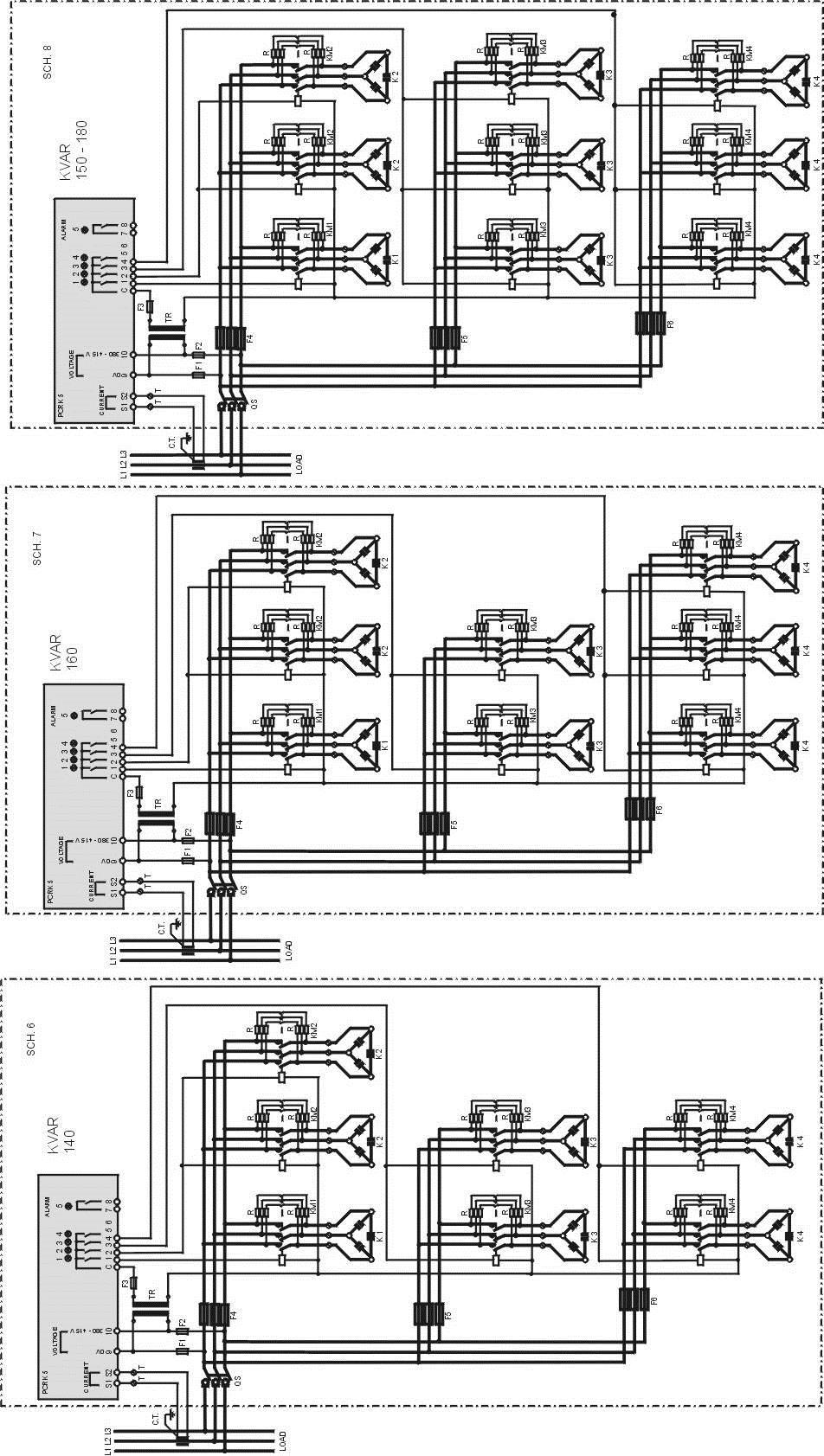
2 Via L.. Da VINCI, 100, 50028, Tavarnelle V.P FIRENZE Tel /118 Fax info@telegroup.it INDEX Automatic power factor correction panels Pages 2 6 Power factor regulator Pages 7 16 Wiring diagrams Pages GENERAL INFORMATION Attention!!! Proper connection and start-up of power factor correction equipment is relatively simple yet it must not ever, under any circumstances, be left up to chance. Consequently, the device will not engage or disengage the batteries of capacitors or it will operate anomalously. In that these panels have all been tested and inspected by the manufacturer, any anomalous operation will be due to faulty connections, and in particular or to a faulty positioning of the current transformer. Therefore, we kindly request that you observe the instructions in this manual and rigorously follow them in the sequence indicated. Thank you for your kind attention and collaboration. Locate the panel in a well aerated space and far from any heat sources: good air circulation is one of the most important factors for proper and long lasting operation. Leave at least 30 cm of space around the panel, so that air may freely enter and exit the area. Do not locate the equipment in humid areas unless it has been specifically requested with a particular protection grade. 1- LOCATION OF THE EQUIPMENT Operational limits: - Relative humidity: max 50% at 40 C 90% at 20 C - Altitude: max metres a.s.l. - Transport and warehousing: temp.-25 to +55 C 2
3 Via L.. Da VINCI, 100, 50028, Tavarnelle V.P FIRENZE Tel /118 Fax info@telegroup.it 2- CURRENT SHORT CIRCUIT To insure that the equipment will not be subject to short circuits it is necessary to install, upstream of the power factor correction panels, whether they are fixed or automatic, a circuit of three am NH type current limiting fuses (or other devices with similar characteristics) with suitable nominal current specifications and power to break the circuit above the presumed short circuit current. When the LCC is not known at the point of installation, it may be approximated by the LCC of the transformer (50 KA). KVAR power LCC max ka From 7.5 to From 20 to From 30 to 60 6 From 65 to From 100 to From 160 to From 200 to From 400 to From 100 to From 150 to From 200 to From 400 to From 550 to KVA V DC% LCC ka
4 For the optimal connection of Automatic PFC System, are necessary some simple operation that have to be absolutely respected. Following, are showed the steps that is necessary to follow for the installation: 1. Earth Connection of Secondary of Current Transformer (C.T.) 2. Connection of Automatic PFC System with optimal size of cables, referred to power indicated on the plate. 3. Power Supply: Three-Phase + PE (excluding special request) 4. Connection of Power Cables on General MCCB, respecting the sequence of Phases. In case of Switch-OFF of Automatic PFC System during the normal operation, please be sure, before open the General MCCB, that all Capacitor Banks are switched-off, following the instruction (please check MAN Mode) C.T. must be positioned on (R L1) Phase, on the top of all loads present on the Power Line that supply the Automatic PFC System During the connection if Automatic PFC System, must be respected the sequence of Phases (R-L1) (S-L2) (T-S3) That condition, can be easily verified using a Voltmeter: measuring, between the Phase where C.T. is positioned (R-L1) and the Phase connected to the clamp R of Switch-Disconnector of Automatic PFC System, the Voltage must be 0 The positioning of C.T. is absolutely necessary for the optimal operation of Automatic PFC System. 4
5 Follow, please find some no-corrected positioning of C.T. Position 2: C.T. installed on the top of all loads, but on (L3-T) Phase, instead of (L1-R) Phase. Position 3: C.T. is installed on the same line of loads!! Position 4: C.T. is installed on Phases that supply Automatic PFC System. In case of installation of Automatic PFC System in presence of MV/LV Transformer, if are present Fix PFC System for the compensation of Transformer, the C.T. must be installed after the Fix PFC System. The figure show the connection of Automatic PFC System in case of presence of MV/LV Transformer in parallel configuration. NOTE: Is necessary to use an ADDER C.T. with 2 or 3 inputs (in reference to the qty of Transformers), where have to be connected the output cables of C.T. The output of C.T. must be connected on Automatic PFC System. Is also necessary to set the value of the Primary of C.T. (as described in appendix B), as amount of the two or three C.T. 5
6 6. REGULATIONS 6.1 INSTRUCTION FOR THE USE OF AUTOMATIC PFC CONTROLLER PCRL Series PCRL is an Automatic PFC Controller, based on a Microprocessor controlled circuit, able to Switch-ON and OFF the banks needed to maintain the selected Power Factor. The instrument effects an RMS value measurement that allows the optimal operation and visualization even in presence of distorted waveformes. The Microprocessor Central Unit, is able to manage all the regulations: Microprocessor PFC Controller LCD Display Membrane Keyboard, 4 keys Serial TTL-RS232 for set-up and automatic Test via PC. Internal temperature sensor. Advanced function (current measurement, capacitor overload, week Power Factor, storing od mx value). PCRL is able to recognize se sense of current of C.T. In case of co-generation plants, is necessary to disable this option (see chapter advanced Menù) and provide to the correct connection of c.t. The Secondary must be Earth-connected. A. Attention: the parameters of PCRL are already Preset and must not be changed. B. The only parameters that the User need to set is the value of the Primary of C.T. 1. When the Automatic PFC will be connected, the Display of PCRL will show C t (Current Transformer) flashing. 2. Press or for setting directly the current value of the Primary of C.T. 3. Press for confirming. 4. Wait a few seconds. 5. PCRL stores the setting and start directly in automatic mode. 6
7 PCRL5/7.. Automatic Power Factor Controller WARNING! INSTRUCTIONS MANUAL Carefully read the manual before the installation or use. This equipment is to be installed by qualified personnel, complying to current standards, to avoid damages or safety Before any maintenance operation on the device, remove all the voltages from measuring and supply inputs and short-circuit the CT input terminals. Products illustrated herein are subject to alteration and changes without prior notice. Technical data and descriptions in the documentation are accurate, to the best of our knowledge, but no liabilities for errors, omissions or contingencies arising there from are accepted. A circuit breaker must be included in the electrical installation of the building. It must be installed close by the equipment and within easy reach of the operator. It must be marked as the disconnecting device of the equipment: IEC /EN Clean the instrument with a soft dry cloth; do not use abrasives, liquid detergents or solvents. Index Introduction Description Keyboard functions Display indications Operating modes Measures Keypad lock Expandability IR programming port Parameter setting through PC Parameter setting through tablets orsmarphones Setting of parameters (setup) from front panel Rapid CT setup Parameter table Alarms Alarm description Default alarm properties Command menu CX02 dongle usage Installation Wiring diagrams Terminal arrangement Mechanical dimensions and Panel cutout Technical carachteristics Manual revision history Introduction The DCRL automatic power factor control unit has been designed to offer state-of-the-art functions for power factor compensation applications. Built with dedicated components and extremely compact, the DCRL combines the modern design of the front panel with practical installation and the possibility of expansion from the rear, where one EXP series module can be slotted. The LCD screen provides a clear and intuitive user interface. 7

8 Description Automatic power factor controller. Flush-mount, standard 96x96mm housing. Backlit LCD screen. Versions: o DCRL3 with 3 relays, expandable to 5 max. o DCRL5 with 5 relays, expandable to 7 max. 4 navigation keys for function and settings. Alarm messages in 6 languages. Expansion bus with 1 slot for EXP series expansion modules: o RS232, RS485, USB communications interface. o Additional relay outputs. High accuracy TRMS measurements. Wide selection of electrical measures, including voltage and current THD with harmonic analysis up to 15 th order. Voltage input separated from power supply, suitable for VT connection in medium voltage applications. Wide-range power supply ( VAC). Front optical programming interface: galvanically isolated, high speed, waterproof, USB and WiFi dongle compatible. Programming from front panel, from PC or from tablet/smartphone. 2-level password protection for settings. Backup copy of original commissioning settings. Built-in temperature sensor. Tool-less panel mount. Front keyboard MODE Key - Used to select among available measurements. Used also to access programming menus. and keys - Used to set values and to select steps. MAN-AUT key - Used to select operating mode between manual and automatic. Display indications Manual mode Inductive / capacitive Automatic mode Cooling fan status Output status Main display Step status Bar graph Active alarm Secondary display Alphanumeric display Operating modes There are three possible operating modes, listed below: TEST Mode When the unit is brand new and has never been programmed, it automatically enters in TEST mode that allows the installer to manually activate the individual relay outputs, so you can verify the correct wiring of the panel. The TEST mode is indicated by three dashes --- shown on the main display. The activation and deactivation of the outputs is done directly by pushing and buttons, but without considering the reconnection time. The TEST mode is automatically left after the parameter programming is done (see Parameter setting chapter). Indication of TEST mode Total number of steps Firmware revision Model variant 8

9 MAN and AUT Modes The icons AUT and MAN indicate the operating mode automatic or manual. To change the mode, press the MAN / AUT button for 1 sec in a row. The operating mode remains stored even after removing and reapplying the power supply voltage. MAN Mode When the unit is in manual mode, you can select one of the steps and manually connected or disconnect it. In addition to the specific icon, the alphanumeric display shows MAN in order to highlight the manual mode condition. Press MODE to view the other measurements as usual. While the display shows MAN, it is possible to select the step to be switched on or off. To select a step, use the or buttons. The selected step will flash quickly. Press MODE to activate or deactivate the selected step. If the selected step has not yet exhausted the reconnection time, the MAN icon will flash to indicate that the transaction has been accepted and will be conducted as soon as possible. Manual configuration of the steps is maintained even when the power supply voltage is removed. When the power returns, the original state of the steps is restored. MAN mode icon Connected steps Tot kvar inserited in MAN Manual step selection enabled Select step Change step status MODE AUT Mode In automatic mode, the controller calculates the optimum configuration of capacitor steps in order to reach the set cos. The selection criteria takes into account many variables such as: the power of each step, the number of operations, the total time of use, the reconnection time, etc. The controller displays the imminent connection or disconnection of the steps with the flashing of their identification number (left). The flashing can last in cases in which the insertion of a step is not possible due to the reconnection time (discharge time of the capacitor). The device initiates automatic corrections when there is an average reactive power request (delta-kvar) higher than 50% of the smallest step, and the measured cosphi is different from the setpoint. Measures The DCRL provides a set of measurements displayed on the alphanumeric display, in conjunction with the current cosphi that is always displayed on the main display. Press the MODE key to scroll through the measures in rotation. After 30 seconds without pressing any buttons, the display automatically returns to the default measurement defined by P.47. If P.47 is set on the ROT, then the measures rotate automatically every 5 seconds. At the bottom of the list of measures it is possible to set the setpoint of the cosphi, acting on the same value set with P.19. Below is a table with the measurements displayed. Measure Icon Description Delta-kvar Δkvar Kvars needed to reach the cosphi setpoint. If delta-kvar is positive cpacitors need to be inserted, if negative to be disconnected. kvar Total kvar of the plant. Δ STEP Number of equivalent steps. MODE Voltage V RMS voltage of the plant current. V HI Maximum peak of measure. MODE Current A RMS current of the plant voltage. A HI Maximum peak of measure. 9
10 MODE Weekly PF WPF Weekly average power factor. PF Instantaneous total power factor. MODE Cap. current %C.CU %C.HI Calculated capacitor current, in % of their nominal. Maximum peak of measure. Temperature C F Temperature of internal sensor. CHI FHI MODE MODE Maximum peak of measure. Voltage THD THDV VH02...VH15 Total harmonic distortion % (THD) of plant voltage. % voltage harmonic content from 2.nd up to 15.th order MODE Current THD THDI IH02 IH15 Total harmonic distortion % (THD) of plant current. % Current harmonic content from 2.nd up to 15.th order MODE Cosphi set point IND CAP Setting of desired cosphi setpoint (same as P.19). MODE Step power % Step residual power, as a percentage of the set rated power. MODE Step counter OPC Operation counter of the step. MODE Step hours H Hour meter of the step insertion. These measures are shown only if the Step trimming function is enabled (P.25=ON) and the advanced password is enabled and entered. Keypad lock A function to exclude all modification to operating parameters can be enabled; measurement viewing is still provided in any case. To lock and unlock the keypad, press and keep MODE key pressed. Then press the key three times and the key twice and after that release MODE. The display will show LOC when the keypad is locked and UNL when it is unlocked. When the lock is enabled, it is not possible to make the following operations: o Operation between automatic and manual mode o Access to set-up menus o Change of cosphi set-point By attempting to conduct the above operations, the display will view LOC to indicate the locked keypad state. 10
11 Parameter table Below are listed all the programming parameters in tabular form. For each parameter are indicated the possible setting range and factory default, as well as a brief explanation of the function of the parameter. The description of the parameter shown on the display can in some cases be different from what is reported in the table because of the reduced number of characters available. The parameter code can be used however as a reference. Note: the parameters shown in the table with a shaded background are essential to the operation of the system, thus they represent the minimum programming required for operation. BASE MENU COD DESCRIPTION ACC UoM DEF RANGE CT primary P.01 Usr A OFF OFF / P.02 P.03 P.04 P.05 P.06 P.07 P.08 P.09 P.10 CT secondary CT read phase CT wiring polarity Usr A 5 1 / 5 Usr L3 L1 Usr Aut Aut Dir Inv Voltage read phase Usr L2-L3 L1-L2 L2-L3 L3-L1 L1-N L2-N L3-N Smallest step power Usr Kvar Rated capacitor voltage Nominal frequency Reconnection time Sensitivity Usr V Usr Hz Aut Aut Adv sec Usr sec L2 L3 50Hz 60Hz Var 11
12 P.11 Step 1 function Usr. OFF P.12 Step 2 function P.13 Step 3 function P.14 Step 4 function P.15 Step 5 function P.16 Step 6 function P.17 Step 7 function P.19 Cos-phi setpoint P.20 Alarm messages language Usr Usr Usr Usr Usr Usr Usr Usr ON NOA NCA FAN MAN AUT A01 A13 = = = = = = 0.95 IND 0.50 Ind 0.50 Cap ENG ENG ITA FRA SPA POR DEU 12
13 P.01 - The value of the primary current transformer. Example: with CT 800/5 set 800. If set to OFF, after the power-up the device will prompt you to set the CT and allow direct access to this parameter. P.02 - Value of the secondary of the current transformers. Example: with CT 800/5 set 5. P.03 It defines on which phase the device reads the current signal. The wiring of current inputs must match the value set for this parameter. Supports all possible combinations of parameter P.05. P.04 - Reading the connection polarity of the CT. AUT = Polarity is automatically detected at power up. Can only be used when working with only one CT and when the system has no generator device. Dir = Automatic detection disabled. Direct connection. Inv = Automatic detection disabled. Reverse wiring (crossover). P.05 - Defines on which and on how many phases the device reads the voltage signal. The wiring of voltage inputs must match the setting for this parameter. Supports all possible combinations of parameter P.03. P.06 - Value in kvar of the smallest step installed (equivalent to the step weight 1). Rated power of the capacitor bank provided at the rated voltage specified in P.07 and referred to the total of the three capacitors for three-phase applications. P.07 - Rated plate capacitor, which is delivered in specified power P.06. If the capacitors are used to a voltage different (lower) than nominal, the resulting power is automatically recalculated by the device. P.08 - Working frequency of the system: Aut = automatic selection between 50 and 60 Hz at power on. 50Hz = fixed to 50 Hz. 60Hz = fixed to 60 Hz. Var = variable, measured continuously and adjusted. P.09 - Minimum time that must elapse between the disconnection of one step and the subsequent reconnection both in MAN or AUT mode. During this time the number of the step on the main page is blinking. P.10 - Connection sensitivity. This parameter sets the speed of reaction of the controller. With small values of P.10 the regulation is fast (more accurate around the setpoint but with more step swithchings). With high values instead we ll have slower reactions of the regulation, with fewer switchings of the steps. The delay time of the reaction is inversely proportional to the request of steps to reach the setpoint: waiting time = (sensitivity / number of steps required). Example: setting the sensitivity to 60s, if you request the insertion of one step of weight 1 are expected 60s (60/1 = 60). If instead serve a total of 4 steps will be expected 15s (60/4 = 15). P11... P18 - Function of output relays : OFF = Not used = Weight of the step. This relay drives a bank of cpacitors which power is n times (n = 1 32) the smallest power defined with parameter P.06. ON = Always on. NOA = Alarm normally de-energized. The relay is energized when any alarm with the Global alarm property arises. NCA = Alarm normally energized. The relay is de-energized when any alarm with the Global alarm property arises. FAN = The relay controls the cooling fan. MAN = Relay is energized when device is in MAN mode. AUT = Relay is energized when device is in AUT mode. A01... A13 = The relay is energized when the alarm specified is active. P.19 - Setpoint (target value) of the cosphi. Used for standard applications. P.20 - Language of scrolling alarm messages. 13
14 ADVANCED MENU COD DESCRIPTION ACC UoM DEF RANGE Password enable P.21 Adv OFF OFF P.22 P.23 P.24 User password Advanced password Wiring type ON Usr Adv Usr 3PH 3PH three-phase P.25 P.26 P.27 P.28 1PH single-phase Step trimming Usr OFF ON Enabled OFF Disabled Setpoint clearance + Usr Setpoint clearance - Usr Step insertion mode Usr STD STD Standard P.29 P.30 P.31 Cogeneration cos setpoint Disconnection sensitivity Step disconnection passing in MAN Lin Linear Usr OFF OFF / 0.50 IND 0.50 CAP Usr sec OFF OFF / Usr OFF OFF Disabled P.32 P.33 P.34 P.35 P.36 Capacitor current overload alarm threshold Adv % Capacitor overload immediate disconnection threshold Adv % ON Enabled 125 OFF / OFF / VT primary Usr V OFF OFF / VT secondary Usr V Temperature UoM Usr C C Celsius P.37 P.38 Fan start temperature Fan stop temperature F Fahrenheit Adv 35 Adv P.39 P.40 P.41 Temperature alarm threshold Adv Step failure alarm threshold Adv % OFF OFF / Maximum voltage alarm threshold Adv % 120 OFF /
15 P.42 P.43 P.44 P.45 P.46 P.47 P.48 P.49 P.50 P.51 P.52 P.53 Minimum voltage alarm threshold Adv % OFF OFF / THD V alarm threshold THD I alarm threshold Adv % OFF OFF / Adv % OFF OFF / Maintenance interval Adv h Bar-graph function Usr Kvar ins/tot Kvar ins/tot Corr att/nom Delta kvar att/tot Default auxiliary measure Usr Delta kvar Deltakvar V A Week TPF Cap. Current Temp THDV THDI ROT Backlight flashing on alarm Usr OFF OFF ON Serial node address Usr Serial speed Usr bps 9.6k 1.2k 2.4k 4.8k 9.6k 19.2k 38.4k Data format Usr 8 bit n 8 bit, no parity 8 bit, odd 8bit, even 7 bit, odd 7 bit, even Stop bits Usr Protocol Usr Modbus RTU Modbus RTU Modbus ASCII P.21 If set to OFF, password management is disabled and anyone has access to the settings and commands menu. P.22 With P.21 enabled, this is the value to specify for activating user level access. See Password access chapter. P.23 As for P.22, with reference to Advanced level access P.24 Number of phases of the power correction panel. P.25 - Enables the measurement of the actual power of the step, performed each time they are switched in. The measure is calculated, as the current measurement is referred to the whole load of the plant. The measured power of the steps is adjusted (trimmed) after each switching and is displayed on the step life statistic page. When this function is enabled, a 15 sec pause is inserted between the switching of one step and the following, necessary to measure the reactive power variation. P.26 P.27 - Tolerance around the setpoint. When the cosphi is within the range delimited by these parameters, in AUT mode the device does not connect / disconnect steps even if the delta-kvar is greater than the smallest step. Note: + means towards inductive, while means towards capacitive. 15
16 P.28 - Selecting mode of steps insertion. Standard mode - Normal operation with free selection of the steps Linear mode - the steps are connected in progression from left towards right only following the step number and according to the LIFO (Last In First Out) logic. The controller will not connect a step when the system steps are of different ratings and by connecting the next step, the set-point value would be exceeded. P.29 - Setpoint used when the system is generating active power to the supplier (with negative active power / power factor ). P.30 - Disconnection sensitivity. Same as the previous parameter but related to disconnection. If set to OFF the disconnection has the same reaction time of connection set with the previous parameter. P.31 - If set to ON, when switching from AUT mode to MAN mode, steps are disconnected in sequence. P.32 Trip threshold for the capacitors overload protection (alarm A08), that will arise after a integral delay time, inversely proportional to the value of the overload. Note: You can use this protection only if the capacitors are not equipped with filtering devices such as inductors or similar. P.33 - Threshold beyond which the integral delay for tripping of the overload alarm is zeroed, causing the immediate intervention of the A08 alarm. P.34 P.35 Data of VTs eventually used in the wiring diagrams. P.36 Unit of measure for temperature. P.37 P.38 - Start and stop temperature for the cooling fan of the panel, expressed in the unit set by P.36. The cooling fan is started when the temperature is >= to P.37 and it is stopped when it is < than P.38. P.39 - Threshold for generation of alarm A08 Panel temperature too high. P.40 - Percentage threshold of the residual power of the steps, compared with the original power programmed in general menu. Below this threshold the alarm A10 step failure is generated. P.41 - Maximum voltage alarm threshold, referred to the rated voltage set with P.07, beyond which the alarm A06 Voltage too high is generated. P.42 - Undervoltage alarm threshold, referred to the rated voltage set with P.07, below which the alarm A05 voltage too low is generated. P.43 - Maximum plant voltage THD alarm threshold, beyond which the alarm A10 THDV too high is generated. P.44 Maximum plant current THD alarm threshold beyond which the alarm A05 voltage too low is generated. P.45 Maintenace interval in hours. When it is elapsed, the alarm A12 maintenance interval will be generated. The hour count increments as long as the device is powered. P.46 Function of the semi-circular bar-graph. Kvar ins/tot: The bar graph represents the amount of kvar actually inserted, with reference to the total reactive power installed in the panel. Curr act/nom: Percentage of actual plant current with reference to the maximum current of the CT. Delta kvar: bar graph with central zero. It represts the positive/negative delta-kvar needed to reach the setpoint, compared to the total kvar installed. P.47 Default measure shown on the secondary display. Setting the parameter to ROT, the different measures will be shown with a sequential rotation. P.48 If set to ON, the display backlight flashes in presence of one or more active alarms. P.49 Serial (node) address of the communication protocol. P.50 Communication port transmission speed. P.51 Data format. 7 bit settings can only be used for ASCII protocol. P.52 Stop bit number. P.53 Select communication protocol. 16
17 Alarms When an alarm is generated, the display will show an alarm icon, the code and the description of the alarm in the language selected. If the navigation keys in the pages are pressed, the scrolling message showing the alarm indications will disappear momentarily, to reappear again after 30 seconds. Alarms are automatically resetted as soon as the alarm conditions that have generated them disappear. In the case of one or more alarms, the behaviour of the DCRL depends on the properties settings of the active alarms. Alarm description ALARM DESCRIPTION A01 Undercompensation In automatic mode, all the available steps are connected but the cosphi is still more inductive than the setpoint. A02 Overcompensation In automatic mode, all the steps are disconnected but the cosphi is still more capacitive than the setpoint. A03 Current too low The current flowing in the current inputs is lower than minimum measuring range. This condition can occour normally if the plant has no load. A04 Current too high The current flowing in the current inputs is lower than minimum measuring range. A05 Voltage too low The measured voltage is lower than the threshold set with P.42. A06 Voltage too high The measured voltage is higher than the threshold set with P.41. A07 Capacitor current overload The calculated capacitor current overload is higher than threshold set with P.32 and P.33. After the alarm conditions have disappeared, the alarm message remains shown for the following 5 min or until the user presses a key on the front. A08 Temperature too high The panel temperature is higher than threshold set with P.39. A09 No-Voltage release A no-voltage release has occoured on the line voltage inputs, lasting more than 8ms. A10 Voltage THD too high The THD of the plant voltage is higher than the threshold set with P.43. A11 Current THD too high The THD of the plant current is higher than the threshold set with P.44. A12 Maintenance requested The maintenance interval set with P.45 has elapsed. To reset the alarm use the command C.01 (see Command menu). A13 Step failure The residual power of one or more steps is lower than minimum threshold set with P

18 18
19 19

20 20
21 21
22 TELEGROUP S.r.l. Via L. Da Vinci, 100, 50028, Tavarnelle Val di Pesa Loc. Sambuca FIRENZE - ITALY Phone /118 Fax
INSTRUCTIONS MANUAL. Automatic Power Factor Controller CRL 8 CRL 12. Technical manual_power factor controller CLL8 CRL12 ENGLISH. V1. 11_15 p.
 GB ENGLISH Automatic Power Factor Controller CRL 8 CRL 12 INSTRUCTIONS MANUAL WARNING! Carefully read the manual before the installation or use. This equipment is to be installed by qualified personnel,
ALPTEC POWER FACTOR CONTROLLER
 ALPTEC POWER FACTOR CONTROLLER ALPTEC3 ALPTEC5 ALPTEC7 ALPTEC12 0 REF : 2008-ALPTEC3.5.7.12-01-ANG CONTENTS I GENERAL INFORMATION. 2 II WAYS TO SET UP THE CONTROLLER.. 4 III OPERATING MODE..6 IV ADVANCED
INSTRUCTION MANUAL. Power Factor Controller - 12 steps Model A12 NOKIAN CAPACITORS. Power Factor Controller A12
 INSTRUCTION MANUAL Power Factor Controller - 12 steps Model A12 NOKIAN CAPACITORS Power Factor Controller A12 1. CONTENTS 1. CONTENTS 1 2. FEATURES 2 3. INSTALLATION, CONNECTION AND APPLYING POWER 2 4.
PLA 33. Power line analyzer. User and service manual. version 2.4
 PLA 33 Power line analyzer User and service manual version 2.4 Content. Front control panel and terminal plate...3 7.2.2. System frequency setting...0 2. Device description...4 7.2.3. Password protection...0
Commissioning Instructions Rev. 03
 Power Factor regulator BLR-CM-T/RT L1 L2 L3 Einspeisung Supply Last Load BLR-CM-T + - Triggereingang/ Triggerinput BEL-TSXX N PE L1 L2 L3 Einspeisung Supply Last Load BLR-CM-RT + - Triggereingang/ Triggerinput
ENA33LCD. Power line analyzer. User and service manual. Obrezija 5 SI-1411 Izlake
 ENA33LCD Power line analyzer User and service manual version 2.9 (FW version 6.8 and newer) ETI, d.o.o. Obrezija 5 SI-1411 Izlake www.etigroup.eu/products-services 1. Front control panel and terminal plate
FCR 06, FCR 12. Power factor correction controller. User and service manual
 FCR 06, FCR 12 Power factor correction controller User and service manual version 2.3 Czech Republic Czech Republic 1 Content 1. Control and signal elements... 3 2. Device description... 4 3. Instruction
A Group brand. Automatic power factor controller ALPTEC 8
 Automatic power factor controller ALPTEC 8 A Group brand Warning! Carefully read the manual before the installation or use. This equipment is to be installed by qualified personnel, complying to current
DMTME-96 2CSG133030R4022 M DMTME-I Operation and assembly instructions 2CSG163030R4022 M CSG445001D0202
 DMTME-96 2CSG133030R4022 M204675 DMTME-I-485-96 2CSG163030R4022 M204685 2CSG445001D0202 GB Operation and assembly instructions DMTME-96: three-phase multimeter for panel mounting, used also in singlephase
Installation and Operating Instructions. Power IT Power Factor Controller RVC
 Installation and Operating Instructions Power IT Power Factor Controller RVC Table of contents Page 1. Read this first... 3 About this Instruction Manual... 3 Safety... 3 Electromagnetic compatibility...
SUPPLY NETWORK ANALYZER CVM-96 SERIES
 SUPPLY NETWORK ANALYZER CVM-96 SERIES (Power Demand) INSTRUCTION MANUAL ( M 981 326 / 00B - GB) (c) CIRCUTOR S.A. ----- Supply network analyzer CVM-96 ------ User's manual --- Page No. 1 CVM-96 SUPPLY
Mounting Instructions / Manual MV1171
 Mounting Instructions / Manual MV1171 POWER FACTOR Controller ESTAmat MH-N Vishay Electronic GmbH ESTA Capacitors Division Revision: 19-April-2011 Hofmark-Aich-Strasse 36 84030 Landshut, Germany Phone
Multifunction network analyzer Q15U Q96U2L - Q96U4... Q15E Q96E MCU - MCUH Programmable transducer MCUU
 Multifunction network analyzer Q15U2... - Q96U2L - Q96U4... Q15E2... - Q96E2... - MCU - MCUH Programmable transducer MCUU OPERATING MANUAL Ipm0163.8 - Edition 06.09 Langer Messtechnik GmbH Soyerhofstrasse
DPF-MAC Auto power factor controller
 Digital Electric& Electronics System DPF-MAC Auto power factor controller MULTI POWER FACTOR AUTOMATIC MULTI POWER FACTOR AUTOMATIC Introduction DPF-MAC increases usage efficiency by controlling the power
Installation and Operating Instructions. Power Factor Controllers RVT
 Installation and Operating Instructions Power Factor Controllers RVT Table of contents Read this first About this Instruction Manual 3 Safety 3 Electromagnetic Compatibility 3 CSA certification 3 2 1.
Power Factor Controller RVT Installation and Operating Instructions
 Power Factor Controller RVT Installation and Operating Instructions Table of contents Read this first... 4 1 Introduction to the controller... 5 1.1 A powerful fully three phase individual controlled power
SECTION LOW VOLTAGE ACTIVE HARMONIC FILTER SYSTEM NEMA 1 ENCLOSED
 SECTION 16280 LOW VOLTAGE ACTIVE HARMONIC FILTER SYSTEM NEMA 1 ENCLOSED PART 1 - GENERAL 1.1 SUMMARY This specification defines the requirements for active harmonic filter systems in order to meet IEEE-519-2014
EASTRON SDM630MCT-RJV / SDM630MCT-RJA User Manual V1.1. Three phase multifunction din rail energy meter
 SDM630MCT-RJV-333mV SDM630MCT-RJA-00mA Three phase multifunction din rail energy meter Plug-in solution; labor saving; wiring mistake free Measures kwh KVarh, KW, Kvar, KVA, P, F, PF, Hz, dmd, V, A, THD,etc.
Installation and Operating Instructions
 Energy Division Installation and Operating Instructions Quadratic Integra 1530 Digital Metering Systems Our commitment. Your advantage. Contents Page 1 Introduction 4 1.1 Measurement Capabilities 5 1.2
JBus/Modbus Communication Card
 JBus/Modbus Communication Card Installation and Operation 05/2018 www.schneider-electric.com Legal Information The Schneider Electric brand and any registered trademarks of Schneider Electric Industries
SUPPLY NETWORK ANALYZER
 SUPPLY NETWORK ANALYZER CVM-144 SERIES (Ethernet) (Ver 6.11 and higher) INSTRUCTION MANUAL (M98203401-03-06A) CIRCUTOR S.A. ----- Supply network analyzer CVM-144 ------ User's manual --- Page No. 1 CONTENTS
Installation Instructions and Reference Handbook. Installation instructions
 Installation Instructions and Reference Handbook Multi-instrument MIB 7000/7000C/7020 4189320016B (UK) DEIF A/S Product information Installation instructions Basic operation DEIF A/S, Frisenborgvej 33
REACTIVE ENERGY REGULATOR
 REACTIVE ENERGY REGULATOR Controller MASTER control VAR FAST (Static operation) INSTRUCTION MANUAL (M021B02-03-18A) 2 SAFETY PRECAUTIONS Follow the warnings described in this manual with the symbols shown
sw rev. 55B DEVICE FOR THE PERMANENT CONTROL OF INSULATION ON THE SUPPLY LINES IN MEDICAL PRACTICE PLACES INSTALLATIONS
 INSTRUCTIONS MANUAL IM831-U v0.92 HRI-R40W sw rev. 55B DEVICE FOR THE PERMANENT CONTROL OF INSULATION ON THE SUPPLY LINES IN MEDICAL PRACTICE PLACES INSTALLATIONS INDEX: GENERAL TYPES ACESSORIES AND OPTIONS
Reactive Power Control Relay RM 2106 / 2112 Operating Instructions. FRAKO Kondensatoren- und Anlagenbau
 Reactive Power Control Relay RM 2106 / 2112 Operating Instructions FRAKO Kondensatoren- und Anlagenbau www.frako.com Figure 1 Front view a b c d e Display for active capacitor stages Display for inductive
DM-45 Digital Multimeter
 INSTRUCTION MANUAL DM-45 Digital Multimeter Read and understand all of the instructions and safety information in this manual before operating or servicing this tool. Description The Greenlee DM-45 Digital
BU: EPBP GPG: DIN Rail Products Devices for the permanent control of insulation on supply lines for medical locations ISOLTESTER-DIG-RZ/RS/PLUS
 INSTRUCTION MANUAL BU: EPBP GPG: DIN Rail Products Devices for the permanent control of insulation on supply lines for medical locations ISOLTESTER-DIG-RZ/RS/PLUS 1/23 More information than that reported
MultiCube Multi-Function Electricity Meter. Installation and Operation
 MultiCube Multi-Function Electricity Meter Installation and Operation PREFACE MultiCube Operating Guide Revision 1.08 Jan 2007 This manual represents your meter as manufactured at the time of publication.
ATS-I USER MANUAL. Tecnoelettra srl Dal Via Vioni Dimo, S.Rocco di Guastalla (RE)
") USER MANUAL ATS-I Tel.+39.0522.832004 P1/17 ATS-I User manual Fax.+39.0522.832012 Tecnoelettra_EN.doc P.1/17 Index General description...3 Electrical specifics...3 Device operative logic...4 Manual mode...4
USER MANUAL ATS-I Tel.+39.0522.832004 P1/17 ATS-I User manual Fax.+39.0522.832012 Tecnoelettra_EN.doc P.1/17 Index General description...3 Electrical specifics...3 Device operative logic...4 Manual mode...4
Installation and Operating Instructions. Power Factor Controller RVT-D
 Installation and Operating Instructions Power Factor Controller RVT-D Table of contents 2 Read this first About this Instruction Manual...3 Safety...3 Electromagnetic Compatibility...3 1. Description 1.1.
Operating Guide October 2006
 Operating Guide October 2006 Safety 1 Safety This manual represents your meter as manufactured at the time of publication. It assumes standard software. Special versions of software may be fitted, in which
POWER CLAMP-ON METER 405
 POWER CLAMP-ON METER 405 ENGLISH User Manual 2 CONTENTS RECEIVING YOUR SHIPMENT... 8 ORDERING INFORMATION... 8 1 PRESENTATION... 9 1.1 THE ROTARY SWITCH... 10 1.2 THE FUNCTION BUTTONS... 11 1.3 THE DISPLAY...
Installation and Operating Instructions Quadratic Integra 1530 Digital Metering Systems
 Installation and Operating Instructions Quadratic Integra 1530 Digital Metering Systems Tyco Electronics UK Limited Crompton Instruments Freebournes Road, Witham, Essex, CM8 3AH, UK Tel: +44 1376 509 509
INSTRUCTIONS MANUAL DEVICE FOR THE PERMANENT CONTROL OF INSULATION ON THE SUPPLY LINES IN MEDICAL PRACTICE PLACES INSTALLATIONS HRI-R40W
 Page 2 / 16 INDEX: GENERAL TYPES ACESSORIES AND OPTIONS INSTALLATION WIRING DIAGRAMS CONNECTING TERMINALS DIAGRAMS WIRING DIAGRAM DESCRIPTION WORKING DESCRIPTION AND KEYBOARD WORKING DESCRIPTION AND PROGRAMMING
Technical reference. 4-quadrant controller. multicomp F144-NC-1V1C6DO6RO-2. Your partner for network analysis. System I English
 Technical reference 4-quadrant controller multicomp F144-NC-1V1C6DO6RO-2 System I English Your partner for network analysis KBR multicomp F144-NC-1V1C6DO6RO-2 KBR Kompensationsanlagenbau GmbH Misprints,
PM-PA/PM-PAC POWER ANALYZER
 PM-PA/PM-PAC POWER ANALYZER 1. INTRODUCTION Power Analyzer is an ideal device to control measure and monitor all electrical parameters of a system. Thanks to its four display rows, all parameters can be
vacon 100 flow ac drives application manual
 vacon 100 flow ac drives application manual vacon 1 TABLE OF CONTENTS Document: DPD01083A Version release date: 16.11.12 Corresponds to software package FW0159V121106.vcx 1. Vacon 100 FLOW - Quick Startup
T/3000 T/3000. Substation Maintenance and Commissioning Test Equipment
 T/3000 Substation Maintenance and Commissioning Test Equipment MULTI FUNCTION SYSTEM FOR TESTING SUBSTATION EQUIPMENT SUCH AS: CURRENT, VOLTAGE AND POWER TRANSFORMERS, ALL TYPE OF PROTECTION RELAYS, ENERGY
T 1000 PLUS Secondary Injection Relay Test Set
 Secondary Injection Relay Test Set Designed for testing relays and transducers Microprocessor controlled With phase angle shifter Frequency generator Test results and settings are saved into local memory
Power Factor Controller BR 6000
 Power Factor Controller BR 6000 Manual Version 2.1 E Power Factor Controller BR6000 Version 2.1E, Oct. 2003 CONTENTS Section 1 General 3 Section 2 Installation of the controller / connection diagram 5
MS2109A AC/DC Clamp Meter. User Manual. Contents
 MS2109A AC/DC Clamp Meter User Manual Contents 1. Safety information 1 1.1 Preparation 1 1.2 Usage 1 1.3 Signs and Labels 2 1.4 Maintenance 2 2. Description 2 2.1 Part name 3 2.2 Switch and button description
T 1000 PLUS. Secondary Injection Relay Test Set. Designed for testing relays and transducers
 Secondary Injection Relay Test Set Designed for testing relays and transducers Microprocessor controlled With phase angle shifter Frequency generator High power outputs Large graphical display Compact
Varlogic NR6, NR12. Power factor controller. User manual
 Varlogic NR6, NR12 Power factor controller User manual Power Factor Controller NR6 / NR12 USER S MANUAL Table of Contents 1. General...3 1.1 Safety...3 1.2 Description...3 2. Installation...5 3. Display...6
ZHUHAI PILOT TECHNOLOGY CO., LTD.
 SPM32 Multifunctional Power Meter SPM32 Multifunction Power Meter Installation & Operation Manual V1.0 ZHUHAI PILOT TECHNOLOGY CO., LTD. Danger and warning! This device can be installed only by professionals.
Integra 1560 and 1580 Digital Transducer Systems
 Integra 1560 and 1580 multi function transducers provide high accuracy
UT232. Operating Manual. Digital Power Clamp Meter
 UT232 Operating Manual Digital Power Clamp Meter Model UT232 OPERATING MANUAL TABLE OF CONTENTS TITLE PAGE Overview Unpacking Inspection Safety Information Rules For Safe Operation International Electrical
Earth Leakage Monitoring System IsoBase IsoHub IsoOut
 2014 11 21 Earth Leakage Monitoring System IsoBase IsoHub IsoOut User Manual Due to our policy of continual improvement, specifications may change without prior notice Page 2 (34) Contents Earth Leakage
Power IT LV Active Filters PQFI PQFM PQFK. The ABB comprehensive solution for active filtering of harmonics
 Power IT LV Active Filters PQFI PQFM PQFK The ABB comprehensive solution for active filtering of harmonics Harmonics and Power Quality Power Quality relates to the amplitude, frequency and distortion of
RI-F200 Series. Single and Three Phase Multifunction Energy Meter. Telephone : +44 (0) Displayed Parameters
 Displayed Parameters") RI-F200 Series Single and Three Phase Multifunction Energy Meter DIN 96 panel mounted -/1A or -/5A current transformer input Single phase or three phase network compatible Programmable voltage and current
RI-F200 Series Single and Three Phase Multifunction Energy Meter DIN 96 panel mounted -/1A or -/5A current transformer input Single phase or three phase network compatible Programmable voltage and current
Power factor correction and harmonic filtering. Automatic power factor regulators R.1
 Power factor correction and harmonic filtering Automatic power factor regulators R.1 R.1 Automatic power factor regulators R.1 - Automatic power factor regulators Selection table R1-4 computer Plus-T Intelligent
Computer-14d - xx - 144a
 POWER FACTOR REGULATOR Computer-14d - xx - 144a INSTRUCTION MANUAL ( M 981 602 / 98B ) (c) CIRCUTOR S.A. -------- POWER FACTOR REGULATOR COMPUTER- 14d --------- Page 2 1.- POWER FACTOR REGULATORS COMPUTER-14d-144a
SMART 96 Piú USER'S MANUAL
 SMART 96 Piú USER'S MANUAL 01/2003 Table of Contents 1. INTRODUCTION... 1 2. SYSTEM ARCHITECTURE... 3 2.1 The RS485 Serial interface: network with up to 31 analysers... 4 2.2 The RS485 Serial interface:
ESTAmat PFC-N. Power Factor Correction Controller. Operating Instruction MV1181. Document number: Rev. 02
 Vishay Electronic GmbH Hofmark-Aich-Str.36 D-84030 Landshut Telefon +49 871 86-0 www.vishay.com Document number: 13157 - Rev. 02 Power Factor Correction Controller ESTAmat PFC-N Operating Instruction MV1181
Power IT LV Active Filters PQFA - PQFL - PQFT
 Power IT LV Active Filters PQFA - PQFL - PQFT The ABB comprehensive solution for active filtering of harmonics Pst Harmonics and Power Quality Harmonics caused by non-linear electrical loads such as variable
Contents. Introduction and description Package contents Device identification PM Options... 80
 Contents 1 Introduction and description Package contents... 77 Device identification... 77 2 Characteristics PM500... 78 Options... 80 3 Installation Front-panel cut-out... 82 Mounting... 82 4 Connections
VAR INSTRUCTION MANUAL (M015B B)
") REACTIVE ENERGY REGULATOR Controller MASTER control VAR INSTRUCTION MANUAL (M015B02-03-18B) 2 SAFETY PRECAUTIONS Followthewarningsdescribedinthismanualwiththesymbolsshownbelow DANGER Warnsofarisk,whichcouldresultinpersonalinjuryormaterialdamage
REACTIVE ENERGY REGULATOR Controller MASTER control VAR INSTRUCTION MANUAL (M015B02-03-18B) 2 SAFETY PRECAUTIONS Followthewarningsdescribedinthismanualwiththesymbolsshownbelow DANGER Warnsofarisk,whichcouldresultinpersonalinjuryormaterialdamage
PowerLogic power-monitoring units. PM700 series power meter. Technical data sheet
 PowerLogic power-monitoring units PM700 series power meter Technical data sheet 2009 Functions and characteristics The PowerLogic PM700 series power meter offers all the measurement capabilities required
AccuSine SWP A. Operation. Active Harmonic Filter 02/
 AccuSine SWP 20 480 A Operation Active Harmonic Filter 02/2015 www.schneider-electric.com Legal Information The Schneider Electric brand and any registered trademarks of Schneider Electric Industries SAS
PM 305 Operating Guide
 PM 305 Operating Guide Northern Design PREFACE PM305 Operating Guide Revision 2.05 October 2000 This manual represents your meter as manufactured at the time of publication. It assumes standard software.
GENERAL INFORMATION...5
 TABLE OF CONTENTS SECTION 1 GENERAL INFORMATION...5 1.1 Device Features and Model Selection... 5 1.2 Correct Usage and Conditions For Safety... 6 1.3 Panel Definitions... 7 1.3.1 Ecras Definitions... 7
V Pg. M1: V, V, V Pg. M1 R1: Relay 1 Pg. M1 R2: Relay 2 (three-phase only) output status output status KW Pg. M2:,, Pg. M2n: neutral Pg. M3: P1, P2, P
 output status output status KW Pg. M2:,, Pg. M2n: neutral Pg. M3: P1, P2, P") Via Vizzano 44-40044 Pontecchio Marconi (Bologna)Italy Tel. +39 051 6782006 - Fax +39 051 845544 http://www.elcontrol-energy.net - e-mail: Italia vendite@elcontrol-energy.net estero: sales@elcontrol-energy.net
Via Vizzano 44-40044 Pontecchio Marconi (Bologna)Italy Tel. +39 051 6782006 - Fax +39 051 845544 http://www.elcontrol-energy.net - e-mail: Italia vendite@elcontrol-energy.net estero: sales@elcontrol-energy.net
INSTRUCTION MANUAL. Power Factor Controller RVT-D Installation and operating instructions
 INSTRUCTION MANUAL Power Factor Controller RVT-D Installation and operating instructions 2 RVT-D INSTRUCTION MANUAL Table of contents Read this first About this Instruction Manual...3 Safety...3 Electromagnetic
Model # PCYFC-10kW-250A PCYFC-20kW-250A PowerCycle Battery Conditioner Operation Manual
 Model # PCYFC-10kW-250A PCYFC-20kW-250A PowerCycle Battery Conditioner Operation Manual MAN-000014-00 REV. B TABLE OF CONTENTS SPECIFICATIONS... 1 CYCLER CONTROLS AND USER INTERFACE... 3 OPERATING PROCEDURE...
JBUS/MODBUS communication card
 JBUS/MODBUS communication card JBUS/MODBUS Installation and user manual 66061 51029066EN/BF - Page 1 Page 2-51029066EN/BF Introduction Thank you for selecting an APC by Schneider Electric product to protect
Energy Management. Type WM14 DIN Advanced version. Product Description 3-phase advanced power analyzer with integrated programming
 Energy Management Type WM14 DI version Protection degree (front): IP40 2 digital outputs 16 freely configurable alarms with OR/AD logic linkable with up to 2 digital outputs RS422/485 serial output (MODBUS-RTU),
Centrale de mesure Power Meter PM500 Merlin Gerin
 Notice d'installation et d'utilisation Installation and user manual Centrale de mesure Power Meter PM500 Merlin Gerin 059473_D Introduction and description Package contents c one PM500 power meter with
Multimeter 500CVD21 RTU500 series
 Remote Terminal Units - Data sheet Multimeter 500CVD21 RTU500 series CT/VT interface with 4 voltage and 24 current inputs for direct monitoring of 3/4 wire 0 300 V AC (line to earth), 0...500 V AC (phase
PEM353. Universal measuring device
 353 Universal measuring device 353_D00335_00_D_XXEN/06.2018 353 Universal measuring device Product description The digital universal measuring device 353 is used to record and display measured quantities
SC-225/SC-250/SC-325/SC-350 STATIC CONTACTOR
 Safety Provisions Do not open the device enclosure. There are no user-servicable parts inside the device enclosure. Ensure that the earth connection of the device is done..!! Warning: Consider that there
Energy Management Energy Meter Type EM21 72R Retro-Fit
 Energy Management Energy Meter Type EM21 72R Retro-Fit Including 3 miniature split-core current sensors 10mm (90A), 16mm (150A) and 24mm (250A) diameter holes Class A (kwh) according to EN50470-3 Class
INTELLIGENT DIGITAL MULTI POWER METER [DIC-MPM]
![INTELLIGENT DIGITAL MULTI POWER METER [DIC-MPM]](/thumbs/89/100574794.jpg "INTELLIGENT DIGITAL MULTI POWER METER [DIC-MPM]") Feature Suit for LV/ HV voltage system Compact design with all real-time measurement Consist of basic unit and optional modules 10 years back-up of integrated energy data Large LCD, high brightness High
Feature Suit for LV/ HV voltage system Compact design with all real-time measurement Consist of basic unit and optional modules 10 years back-up of integrated energy data Large LCD, high brightness High
53U MULTI POWER MONITOR OPERATING MANUAL MODEL 53U CONTENTS. (4 digital displays)
") OPERATING MANUAL MULTI POWER MONITOR (4 digital displays) MODEL 53U 53U CONTENTS BEFORE USE... 2 POINTS OF CAUTION... 2 LIGHTNING SURGE PROTECTION... 2 COMPONENT IDENTIFICATION... 3 INSTALLATION... 4 TERMINAL
OPERATING MANUAL MULTI POWER MONITOR (4 digital displays) MODEL 53U 53U CONTENTS BEFORE USE... 2 POINTS OF CAUTION... 2 LIGHTNING SURGE PROTECTION... 2 COMPONENT IDENTIFICATION... 3 INSTALLATION... 4 TERMINAL
PFC POWER FACTOR CONTROLLERS POWER NEEDS CONTROL
 PFC POWER FCTOR CONTROLLERS POWER NEEDS CONTROL 1 PFC power factor controllers utomatic power factor correction controller series PFC 6, 8, 12 RS DESCRIPTION n essential way of electrical energy cost reduction
SUPPLY NETWORK ANALYZER. CVMk SERIES. CVMk-4C SERIES INSTRUCTION MANUAL. ( M / 00 B - Manual 1 / 2 ) (c) CIRCUTOR S.A.
 (c) CIRCUTOR S.A.") SUPPLY NETWORK ANALYZER CVMk SERIES & CVMk-4C SERIES INSTRUCTION MANUAL ( M 981 171 / 00 B - Manual 1 / 2 ) (c) CIRCUTOR S.A. ----- Supply network analyzer CVMk and CVMk-ITF ------ Manual 1 / 2 --- Page
SUPPLY NETWORK ANALYZER CVMk SERIES & CVMk-4C SERIES INSTRUCTION MANUAL ( M 981 171 / 00 B - Manual 1 / 2 ) (c) CIRCUTOR S.A. ----- Supply network analyzer CVMk and CVMk-ITF ------ Manual 1 / 2 --- Page
CONTROL MANUAL. Dry-Pic 09PE - 09VE
 CONTROL MANUAL Dry-Pic 09PE - 09VE Translation of the original document 003, 04.01 EN CONTENTS PAGE 1 - IMPORTANT RECOMMENDATIONS 1.1 Power supply 1. Electronic board specifications 1.3 Caution 1.4 Earth
Modbus communication module for TCX2: AEX-MOD
 Modbus communication module for TCX2: Communication Specification TCX2 is factory installed in TCX2 series controllers with -MOD suffix, and is also available separately upon request for customer installation
SECTION 16483D ADJUSTABLE FREQUENCY DRIVE - MICRODRIVE (MVX <10-HP)
") ADJUSTABLE FREQUENCY DRIVE - MICRODRIVE (MVX
ADJUSTABLE FREQUENCY DRIVE - MICRODRIVE (MVX
RISH Master 3440i/3440iDL 0.2S
 Operating Manual RISH Master 3440i/3440iDL 0.2S as per IEC62053-22 Touch Screen Digital Multi-Function Meter Installation & Operating Instructions Section Contents 1. Introduction INDEX 2. Measurement
POWER FACTOR CONTROLLERS ERN / 11214
 Gruppo Energia s.r.l. Via Cavezzo, 25045 Castegnato (BS)- Italy Tel: 030-320301 Fax: 030-2411006 www.gruppoenergia.it - info@gruppoenergia.it POWER FACTOR CONTROLLERS ERN 11206 / 11214 Operating Manual
GB QUICK GUIDE FOR THE CONFIGURATION OF VARIABLE SPEED DRIVES
 GB QUICK GUIDE FOR THE CONFIGURATION OF VARIABLE SPEED DRIVES LOVATO ELECTRIC S.P.A. 24020 GORLE (BERGAMO) ITALIA VIA DON E. MAZZA, 12 TEL. 035 4282111 FAX (Nazionale): 035 4282200 FAX (International):
Digital Electronic Thermostat With RF
 RT300RF Manual Altech 005_89 06/05/2014 08:56 Page 1 Digital Electronic Thermostat With RF Instruction Manual Model No ALTHC015 RT300RF Manual Altech 005_89 06/05/2014 08:56 Page 2 2 ALTHC015 INSTRUCTION
RETROFITTING. Motor Protection Relay. Two mountings are available, Flush Rear Connection (EDPAR) or Projecting Rear Connection (SDPAR).
 or Projecting Rear Connection (SDPAR).") RETROFITTING Motor Protection Relay NPM800R (R2 case) and NPM800RE (R3 case) are dedicated to the refurbishment of 7000 series (R2 and R3 cases) of CEE relays providing the protection of medium voltage
RETROFITTING Motor Protection Relay NPM800R (R2 case) and NPM800RE (R3 case) are dedicated to the refurbishment of 7000 series (R2 and R3 cases) of CEE relays providing the protection of medium voltage
ULTRA RAPID POWER QUALITY ANALYZER
 ULTRA RAPID POWER QUALITY ANALYZER Ultra rapid (cycle by cycle) advanced electrical network analysis Complete network harmonics analysis, up to 63 rd harmonic High visibility, 5 graphic LCD screen with
T 1000 PLUS. Secondary Injection Relay Test Set. Designed for testing relays and transducers
 Secondary Injection Relay Test Set Designed for testing relays and transducers Microprocessor controlled With phase angle shifter Frequency generator Test results and settings are saved into local memory
Model UT233 OPERATING MANUAL
 Model UT233 OPERATING MANUAL TABLE OF CONTENTS TITLE PAGE Overview Unpacking Inspection Safety Information Rules For Safe Operation International Electrical Symbols The Meter Structure A. The Meter Front
POWER ANALYZER CVM-MINI SERIES INSTRUCTION MANUAL M A CIRCUTOR, SA
 POWER ANALYZER CVM-MINI SERIES INSTRUCTION MANUAL M98174001-03-15A CIRCUTOR, SA CONTENTS 1 BASIC INSTRUCTIONS... 3 1.1 Checks on receipt.... 3 1.2 Main features... 3 1.3 Electrical parameters... 3 1.4
Temperature Controller model MFC-301/T-Dry. Version for Dry Transformers and Motors. Technical Manual. Licht
 Temperature Controller model MFC-301/T-Dry Version for Dry Transformers and Motors Technical Manual Licht Contents 1 Introduction 2 2 Operating principle 3 2.1 General principle 3 2.2 RTD operation 3 3
ENCORE 300 SERIES INSTALLATION AND OPERATING INSTRUCTIONS
 ENCORE 300 SERIES INSTALLATION AND OPERATING INSTRUCTIONS Copyright 2002-2006 PRI Ltd. 9600-3004-2 Issue C Information contained within this document is subject to change without notice and does not represent
Modular Metering System ModbusTCP Communications Manual
 Modular Metering System Manual Revision 7 Published October 2016 Northern Design Metering Solutions Modular Metering System ModbusTCP 1 Description The multicube modular electricity metering system simultaneously
DIRIS A40/A41 RS485 PROFIBUS DP COM. Operating instructions. PROFIBUS Certification
 DIRIS A40/A41 RS485 PROFIBUS DP Operating instructions F GB D I NL E P ON 1 COM PROFIBUS Certification SOCOMEC GROUP SWITCHING PROTECTION & UPS Systèmes de Coupure et de Protection Industrial Switching
CROSS Chassis from 160 A to 450 A
 CROSS Chassis from 160 A to 450 A STS CATALOGUE Important note! The technical data enclosed is for general information. Please note that the operating instructions and references indicated on the products
ATK Clamp Meter
 ATK-2209 Clamp Meter User s Manual Title CONTENTS Page I. SAFETY INFORMATION... 1 II. TECHNICAL SPECIFICATIONS... 2 2-1 Environment Conditions... 2 2-2 Maintenance... 2 2-3 Features... 2 2-4 General Specifications...
SUPPLY NETWORK ANALYZER
 SUPPLY NETWORK ANALYZER CVM-144 SERIES (PROFIBUS-DP) INSTRUCTION MANUAL ( M 981 704 / 01A - GB) CIRCUTOR S.A. ----- Supply network analyzer CVM-144 (PROFIBUS) ------ --- Page No. 1 CONTENTS page 1.- DELIVERY
APPARECCHIATURE AUTOMATICHE DI RIFASAMENTO MANUALE OPERATIVO D INSTALLAZIONE USO E MANUTENZIONE
 APPARCCHIATUR AUTOMATICH DI RIFASAMTO MAUAL OPRATIVO D ISTALLAZIO USO MAUTZIO AUTOMATIC POWR FACTOR CORRCTIO QUIPMT OPRATIG AD ISTALLATIO MAUAL US AD MAITAC Italfarad S.p.A. Via IV ovembre n.1 40061 Minerbio
APPLICATION: The heart of the system is a DSR 100 Digital Static Regulator used in conjunction with standard SCR based rectifier bridges.
 APPLICATION: Basler Electric offers a New Line of digitally controlled brush (static) or brushless excitation systems designed for use with existing Hydro, Gas as well as Diesel driven generators requiring
NO WARRANTIES OF ANY KIND ARE IMPLIED ON THE INFORMATION CONTAINED IN THIS DOCUMENT.
 MODBUS/BECO2200-M3425A Communication Data Base for M-3425A Integrated Protection System Device I.D. = 150 Specifications presented herein are thought to be accurate at the time of publication but are subject
LCR METER Model:
 LCR METER Model: 72-10465 1 CONTENTS Page Number Details 3 Important Safety Information 3 Measurement Range & Accuracy 3 Ambient Conditions 4 Features 4 Impedance Explanation 4 Measurement Mode 5 LCD Description
RTU560. Multimeter 560CVD03. Power Measuring Display. Characteristics. Application. Data Sheet Multimeter 560CVD03
 Multimeter 560CVD03 Without LCD Display There are several versions available: With LCD Display Figure 1 Type Display LO HI 1A 5A Versions R0031 3U3I x x x R0035 3U3I x x x R0051 3U3I x x x R0055 3U3I x
DIRIS A40/A41 RS485 PROFIBUS DP. Operating instructions F GB D I NL E P. SOCOMEC GROUP switching PROTECTION & ups
 DIRIS A40/A41 RS485 PROFIBUS DP Operating instructions F GB D I NL E P SOCOMEC GROUP switching PROTECTION & ups 2 DIRIS A20 - Réf. : 536 182 A GB 876_786_A_gb.indd 2 3/04/09 10:50:47 GB Contents PRELIMINARY
MANUAL PCE-UT232
 www.pce-group-europe.com PCE- Deutschland Gmb H & Co. KG Tel: +49 029 03 976 99-0 Fax: +49 029 03 976 99-29 info@warensortiment.de www.warensortiment.de PCE Group Ibérica S.L. Tel: +34 967 543 548 Fax: