Installation and Operating Instructions. Power Factor Controller RVT-D
|
|
|
- Joel Russell
- 6 years ago
- Views:
Transcription


1 Installation and Operating Instructions Power Factor Controller RVT-D
2 Table of contents 2 Read this first About this Instruction Manual...3 Safety...3 Electromagnetic Compatibility Description 1.1. RVT-D Features Front View Full Graphics Display and Keypad Installation 2.1. Mounting Rear View Leads Connection Wiring Diagram Easy Start 3.1. Menu Navigation Starting the RVT-D Easy Commissioning Description Parameters Automatic Commissioning Menus Chart Measurements 5.1. Measurements Description Overview System Values Event Logging Description Recorded values Example Measurements Printing Settings 6.1. Change Mode (AUTO MAN SET) Settings Protection Automatic Mode (AUTO) Manual Mode (MAN) Set Mode (SET) Commissioning (SET Mode) Automatic Guided Manual Settings (SET Mode) Description of Parameters Control: closed loop Control: open loop Control: external trigger Restore Default settings Input / Output Configuration Various configuration Communication (Printer or Modbus) Test Function Settings Printing Bank Monitoring...48 Appendices A1. Dimensions...49 A2. Technical Specifications...50 A3. Testing & Troubleshooting...52 A4. Post Alarm Restarting Procedure...55 A5. Check in case of maloperation of RVT-D...56 A6. Phase Shift Table...57 A7. RVT-D cabling possibilities...58 A8. Voltage measurement and power supply connection...59


3 Read this first About this Instruction Manual This Instruction Manual is designed to help you quickly install and operate the RVT-D Controller. Before installation and operation of the RVT-D Controller, read this notice carefully. Keep it at the disposal of people in charge of installation, maintenance and operation. Safety Installation, maintenance and operation of the RVT-D Controller must be performed by qualified electricians. Do not work under voltage. For cleaning, remove the dust with a dry cloth. Do not use abrasives, solvents or alcohol. Before cleaning please turn off the power supply and voltage measurement circuit. Do not open the RVT-D Controller s housing. There are no user serviceable parts inside. Disconnect the voltage before replacing the fuse. The RVT-D Controller is connected to two current transformers. Do not unplug the current transformers connections before making sure they are short-circuited or connected to another parallel load of sufficiently low impedance. Failure to do so can create dangerous over voltages. Do not use this product for any other purpose than its original aim. Electromagnetic Compatibility This RVT-D Controller has been verified for compliance with EU (European Union) directives for EMC (electromagnetic compatibility) for operation at 50 Hz and bears the CE marking to this effect. When an apparatus is used in a system, EU directives may require that the system be verified for EMC compliance. The following guidelines are helpful in improving the EMC performance of a system: Metallic enclosures generally improve EMC performance. 1. Run cables away from apertures in the enclosure. 2. Run cables close to grounded metallic structures. 3. Use multiple ground straps for doors or other panels parts as required. 4. Avoid common ground impedances. The RVT-D Controller is UL Recognized. The RVT-D Controller is CSA certified for use in 120Vac system voltage. 3

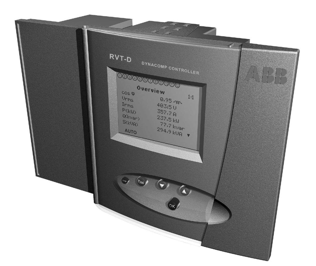
4 1. Description 1.1. RVT-D Features The RVT-D Controller is the control unit of an automatic capacitor bank equipped with static switches (dynamic compensation). It performs the switching of capacitors with a view to reaching a user-defined target cos ϕ and/or to reducing voltage drops. All the switching parameters may be programmed automatically or manually (description in paragraphs 6.2 and 6.3). The target cos ϕ and the control mode (open loop / closed loop / external trigger) may be programmed (description in paragraph 6.3). Additionally the RVT-D Controller provides useful functions: Measurements (description in paragraph 5.1). Protection against unexpected phenomena and/or unauthorized use (description in paragraphs 6.1.1, 6.1.4, , and ). Logging of data and alarm messages (description in paragraphs 5.4 and 7). Checking and testing of outputs status (description in paragraphs 6.5 and 7). Moreover with the addition of optional accessories, the RVT-D provides: Printout of measurements and parameters. Temperature measurements. Each accessory is delivered with its own Instruction Manual Front View Mounting bracket Protective door Full Graphics Display Keypad 4 Help button
 Modes Keypad Help on the highlighted item To go")

5 1.3. Full Graphics Display and Keypad Full Graphics Display Active outputs Locking switch Highlighted item Settings protection Graphic Display Number Alarm Next menus Next item(s) Modes Keypad Help on the highlighted item To go back to the previous window or to leave the current menu or item selection without making changes To go up or down the item list or to decrease or increase a value To go to the next menu or to validate a modification or an operation 5


6 2. Installation 2.1. Mounting Step 1 : Slide the RVT-D (a) perpendicularly to the Capacitor Bank Cubicle (b). Step 2 : Rotate the RVT-D to insert it into the Capacitor Bank Cubicle. Step 3 : Insert the Mounting Bracket (c) in the corresponding Fixation Holes (d) of the RVT-D. Step 4 : Pull the Mounting Bracket backwards. Step 5 : Turn the Screw (e) into the Mounting Bracket and tighten until the RVT-D is secured in place. (c) Step 2 Step 3 Step 4 Step 1 (d) (a) Step 5 (e) (b) Repeat steps 3 to 5 for the bottom Mounting Bracket. 6
7 2.2. Rear View Power supply N.C. Voltage measurement Opto Vdc External trigger input1 Current Transformer Opto Vdc External trigger input2 CAN ML2 ML3 + - k l + - Output connection common Outputs (open collector type) RJ 11 - external probe T1 input RS485 Modbus adapter or RS232 (Printer connection) RJ 11 - external probe T2 input Capacitor bank current transformer x/1a CT Output relay ALARM Locking switch 2.3. Lead Connections 1. Push the lever of the connector backwards with a screwdriver. 2. Insert the wire (up to 2.5 mm 2 /single core) in the corresponding connection hole while keeping the pressure on the lever. 3. Release the screwdriver. 4.The wire is properly connected. 7
8 2.4. Wiring diagram PL2, PL3 : power supply ML2, ML3 : measurement OPTO1 : external trigger input1 k, l : network curent transformer OPTO2 : external trigger input2/dynaswitch status input T1, T2 : temperature probe inputs H, L : CAN : for controlling up to 32 Dynaswitches A, A : output connection common 1-12 : outputs (open collector type) F1, F2 : capacitor bank current transformer (1A) M1, M2 : output relay ALARM Important comment: please note that the network CT must be placed in the same phase as the capacitor bank CT. 8

9 3. Easy start 3.1. Menu navigation 3.2. Starting the RVT-D When the RVT-D is powered-up, the Welcome menu is displayed. The RVT-D is in MAN mode and needs to be set in SET mode in order to commission it or to modify its parameters (see paragraph 6.1) 9
10 3.3. Easy commissioning Description The RVT-D performs automatic commissioning including: automatic recognition of : - special connection (C.T. leads) - number of outputs - type of switching sequence automatic setting of : - Qstep - Istep - Invert Icap Parameters Requested parameters during the easy commissioning process are: CT scale-net : Current Transformer ratio (for instance a 250A / 5A CT has a CT scale-net of 50). Target cos ϕ : Target displacement power factor CT scale-cap : Capacitor bank current transformer ratio. x/1a CT V scaling : external voltage transformer ratio. Control : regulation type: open loop, closed loop and external trigger Increase or decrease the V scaling value using the buttons Enable or disable the CAN control using the buttons Select the node type using the buttons 10
.")

11 Automatic commissioning Note: 1 ) if you have a short-circuit on the CT s secondary winding do not forget to open it after having connected the current input of the PF Controller 2 ) if a transformer is used for the voltage measurement, the Vscaling value has to be changed accordingly (see paragraph 6.3.). Comment: when the icon appears in the upper left-hand corner of the display, this means that the RVT-D is locked. SET Mode access is denied and commissioning cannot be performed until the RVT-D is unlocked (see description in paragraph 6.1.1) Increase or decrease the CT scale-net value using the buttons Increase or decrease the CT scale-cap value using the buttons Select the control mode using the buttons Increase of decrease the target cos ϕ value using the buttons then press Automatic commissioning is now completed. The RVT-D will return automatically to AUTO mode if no key is pressed for 5 minutes. To return to AUTO mode manually select Automatic in the Change mode menu. 11
12 4. Menus chart Welcome 1 Measurements 2 Settings 3 Bank monitoring 4 About RVT-D 1:1 Overview 1:2 System values 1:3 Event logging 1:4 Print 2:1 Change mode Automatic Manual Set 2:2 Commissioning Automatic Guided 2:3 Manual settings Control 2:3:2 CAN 2:3:3 Bank settings 2:4 I/O Configuration Temp. unit Contrast 2:4:3 Communication 2:5 Test function Test alarm Test outputs Print settings Diagnosis Alarm logging Nodes overview 2:3:4 Installation settings 2:3:5 User settings Restore default settings 12
13 5. Measurements 5.1. Measurements Description Designation Unit Description Voltage Range (1) Accuracy Maximum Value Displayed Vrms V1 Frequency THDV V harm. table V harm. chart V V Hz % Rms Voltage Rms voltage at the fundamental frequency Fundamental voltage frequency Total harmonic voltage distortion on voltage Voltage harmonics displayed in a table Voltage harmonics displayed in a bar graph Up to 690Vac Up to 690Vac 45Hz - 65Hz 0-300% 2 nd -49 th 2 nd -49 th ± 1 % ± 1 % ± 0.5% ± 1 % 100 kv 100 kv 40Hz - 70 Hz 300 % See later in this paragraph See later in this paragraph Current Irms I1 THDI I harm. table I harm. chart I1-cap A A % A Rms Current Rms current at the fundamental frequency Total harmonic current distortion on current Current harmonics displayed in a table Current harmonics displayed in a bar graph Rms capacitor current at the fundamental frequency 0-5 A 0-5 A 0-300% 2 nd -49 th 2 nd -49 th 0-1 A ± 1 % 100 ka ± 1 % 100 ka ± 1 % 300 % See later in this paragraph See later in this paragraph ± 3 % 100 ka Power Cos ϕ (2) PF (3) P Q S Q N W var VA var Displacement power factor (2) Power factor (3) Active power Reactive power Apparent power Missing power to reach the pre-set alarm cos ϕ Missing capacitor steps to reach the pre-set alarm cos ϕ kw 0-10 kvar 0-10 kva 0-10 kvar ± 0.02 ± 0.02 ± 2% ± 2% ± 2% ± 2% MW Mvar MVA Mvar Temperature (optional) T1 T2 C or F C or F Temperature T1 (optional external probe 1) Temperature T2 (optional external probe 2) -40 C C -40 C C ± 2 C ± 2 C -40 C C -40 C C - All the measurements are averaged over one second, except Q and N for which the maximum values are given every second. Comments: (1) the range values have to be multiplied by the CT ratio (Irms - I1 I1-cap P Q S Q) and the PT ratio (Vrms - V1 - P - Q S - Q). - If a transformer is used for the voltage measurement, the harmonic voltage measurements may be erroneous due to the filter behaviour of the transformer. The use of a high quality transformer should minimise the error. Explanatory note : Power factor Displacement power factor (2) Displacement power factor or cos ϕ : calculation based on the fundamental value of the measurements. This value is used as the reference value by Electricity Supplies Companies. (3) Power factor : calculation based on the fundamental and harmonic values of the measurements.the power factor is always lower than or equal to the displacement power factor. 13
 Comment: accuracy on voltage (current) harmonic measurements: ± 1 % of Vrms (Irms)")
14 Voltage (current) harmonic chart Go left or right in the chart using the buttons (measurements up to the 49 th harmonic) Voltage (current) harmonic table Go down or up in the table using the buttons (measurements up to the 49 th harmonic) Comment: accuracy on voltage (current) harmonic measurements: ± 1 % of Vrms (Irms) 14


15 5.2. Overview The Overview menu displays all measured items in a list. The user may customize the display of the measurement values to his particular needs. Customization process : - select the measured parameter that you want to move. - press OK. The selected parameter starts flashing. - press or to move the selected parameter up or down the list. Once the selected parameter is located in the desired position in the list, press 5.3. System values The System Values menu displays all measured system values sorted by type. 15
 and since the last")


16 5.4. Event logging Description: The event logging function allows the user to log, for each significant measured item (see list here below) and since the last clearance: - the maximum (or minimum) value - the duration above (or below) the threshold. Threshold Maximum recorded 16 Once a threshold has been set (see example in paragraph ), the RVT-D starts recording the maximum (or minimum) value automatically as well as the total duration until a reset is performed. Total duration = t 1 + t 2 + t 3 Time

![P [W], Q [var], S [VA], THDV [%], THDI [%], Q [var], frequency (1) [Hz], T1 (1) [ C or F] and T2 (1) [ C or F].](/docs-images/71/65793658/images/17-1.jpg "(1) Minimum values and duration below a threshold are also recorded for the frequency and the temperatures. 5.4.3. Example Recording of information on Vrms. Voltage network : 400V.")
17 Recorded values The event logging function allows the user to record the time during wich a measured value exceeds a threshold and its maximum value for the following parameters : Vrms [V], Irms [A], P [W], Q [var], S [VA], THDV [%], THDI [%], Q [var], frequency (1) [Hz], T1 (1) [ C or F] and T2 (1) [ C or F]. (1) Minimum values and duration below a threshold are also recorded for the frequency and the temperatures Example Recording of information on Vrms. Voltage network : 400V. The recorded information (maximum value and total duration) may be cleared by selecting and validating the Reset item Measurements printing Print once: when selected and validated, all the measurements are printed once. Repeat printing: when set on, all the measurements are repeatedly printed according to the Repeat-Delay. Repeat-Delay: time between two successive measurement printings. 17


18 6. Settings 6.1 Change Mode (AUTO MAN SET) The Change Mode menu allows the operating mode of the RVT-D to be selected. Comment: after a power outage, once the power returns the RVT-D starts in the Mode previously selected, except for the SET Mode. In this case, the RVT-D will start in AUTO mode and changes previously made in SET Mode that have not been validated are not saved Settings Protection Unauthorised modification of all or some of the parameters can be prevented in a number of ways. Locking switch: A locking switch, located at the back of the RVT-D (see RVT-D rear view in paragraph 2.2), allows the RVT-D to be locked in AUTO mode or in MAN mode. When the lock is set: - a will appear in the upper left-hand corner of the graphics display. - a will appear beside the Change mode menu, Commissioning menu and all the settings. - access to the Change mode and Commissioning menus will be denied. - no modification can be made to the settings (including the Event logging settings). - the setting values may be consulted. AUTO/MAN mode: Select the mode with the buttons then press The RVT-D has three functional modes which are described in the following paragraphs. When the AUTO or the MAN mode is set: - a will appear beside all the settings. - access to the Commissioning menu will be denied. - access to the Change mode menu will be allowed. - the setting values may be consulted. - no modification can be made to the settings (except to the Event logging settings). 18
19 Bank settings item: The bank settings item, available at the bottom of the bank settings list, can be either locked or unlocked. When the bank settings item is set as locked (whatever the Mode used): - a will appear beside all the bank settings. - no modification can be made to the bank settings - the bank settings values may be consulted. - the installation and user settings can be modified, if the locking switch is unlocked. Once locked, the bank set item can be unlocked by entering the following key sequence (in SET mode) : Automatic Mode (AUTO) Steps are automatically switched on and off to reach the target cos ϕ (and/or to reduce voltage drop) according to the parameter settings related to the selected control type. In Auto Mode: - settings and measurements can be consulted. - the measurements list (Overview menu) can be customized. - the event logging function can be used Manual Mode (MAN) Steps may be switched on and off manually by pressing the or buttons. Switching is performed according to the switching delay time, the switching strategy and type of sequence. Once the MAN Mode is selected, a message informs the user that he can go directly to the overview menu where the switch ON 1 step and switch OFF 1 step items are available. 19
.")

.")
20 Set Mode (SET) In Set Mode, the RVT-D parameters can be set manually and automatic or guided commissioning can be performed. Comment: - SET Mode access is denied when the RVT-D is locked (see paragraph ). - the RVT-D returns automatically to AUTO mode when no key is pressed for more than 5 minutes Commissioning (SET mode) Easy Commissioning: please refer to the complete description in paragraph Guided Commissioning Press to validate The RVT-D performs a guided commissioning process. The following parameters (see table below) must be entered. Some of them are not asked when the parameter Bank settings has been locked (see in table below). 20 Comment: 1 ) before performing guided commissioning, please make sure that: - the RVT-D is unlocked (description in paragraph ) - the RVT-D is in SET Mode (description in paragraph ) 2 ) if you have a short-circuit on the CT s secondary winding do not forget to open it after having connected the current input of the PF Controller.
21 Guided Commissioning Parameters Parameter Description CT scale-net Current Transformer ratio. Phase shift Phase shift between voltage and current introduced by the measurement connections. The phase shift is 90 (default setting) when the RVT-D is connected as shown on wiring diagram (see paragraphe 2.4). For other connections, please see appendix A.5. CT scale-cap (*) Capacitor bank Current Transformer ratio. x/1a CT Invert Icap To invert the capacitor bank Current Transformer measurement, if required by the polarity of the network CT. 1Ph/3Ph (*) Bank connection type and RVT-D measurement connection. V scaling (*) External voltage transformer ratio. V nomimal (*) Nominal bank voltage. CAN control (*) Flag allowing the DYNASWITCHES to be controlled through CAN Bus. Node type (*) When using CAN, specify what type of step is switched (1Ph/3 Ph or Cap/Reactor). Sequence (*) Relative reactive power value of each output. Q step (*) Smallest reactive power difference between steps. Control Regulation type: open loop, closed loop or external trigger. Target cos ϕ Target displacement power factor. Bank settings (*) To lock the access to the bank settings (see paragraph 6.1.1, , and depending on control mode selected). For more information regarding these parameters, a complete description is available in the following paragraph. (*) These parameters are not asked when the parameter bank settings has been previously set locked. 21

22 6.3. Manual settings (SET Mode) Description of Parameters The Settings menu gives access to all the RVT-D parameters that are grouped in 3 categories: - Bank settings: gathers all configuration parameters related to the automatic bank - Installation settings: gathers installation parameters of the RVT-D - User settings: gathers additional installation parameters which can be modified by the installer or the user. These parametres are related to the control item. The control item allows to set the RVT-D regulation type: - open loop: the load current is measured. The RVT-D computes the required compensating current and switches steps accordinlgy. - closed loop: the resulting current (load current + compensating current) is measured. The RVT-D switches steps in order to minimize this resulting current. - external trigger: the RVT-D switches steps based on an external signal provided by the load that must be compensated. Before setting parameters, please make sure that access is allowed : see paragraph Control: closed loop Closed loop CAN The CAN menu allows to set and read the parameters related to the control of steps through CAN bus. CAN control: when enabled, both synchronisation and control of each steps are performed through CAN bus. Otherwise, only the On/Off control is performed through output transistors. When enabled, if any step declared valid in the sequence reports a non-ready status, an error message is displayed. Any uncontrolled change of these parameters can cause erratic behavior or even destroy parts of the DYNASWITCH. The settings must be applied by experienced users. Node type: for characterising the type for load to be switched by the DYNASWITCH. This allows to switch 1Ph/3Ph loads as well as Capacitor/Reactor loads. For proper operation when switching reactors, please invert the CT measurement physically or by setting the phase shift accordingly. In this condition, the power (P & Q) measurements will be displayed with the opposite polarity than they are actually. Synchro advance: for tuning the phase advance of the synchronising signal compared with the zero-crossing rising edge of the voltage measured by RVT-D. It is expressed in PE/4, which means that 128 represent a whole fundamental period. Dead time: for tuning the duration while no Thyristor is fired between Thyristor transitions. It is expressed in degree.
23 Nodes overview: gives for all declared nodes in the RVT-D the status. The below lists the different status reported by RVT-D about DYNASWITCH (one status per node Id): Reporting "Missing" Reporting "Ready" Reporting "Fuse err." Reporting "Sync. err." Reporting "Wire err." Reporting "Rst del." Reporting "Discharg." Reporting "Disc. War." Reporting "Multiple" No node with this Id Node ready to switch Thyristor over temperature Protistor opening RVT-D sends inconsistent synchronizing signal When the AC voltage sensed across one of the switch is not compliant with type of load compared with the top synchro received from RVT-D. This protects against wrong cabling of Gates / Power / RVT-D. The DYNASWITCH is in the reset phase after an initialisation. If the DC voltage sensed on the switch after the reset delay is still higher than 100V, then the switch waits until it is below 100V before switching ON. In case of total failure of the discharge resistors, then it will prevent the DYNASWITCH to switch. When the DC voltage sensed across one of the switch depicts a problem in the discharge resistors, it reports a warning, but the switching goes on (but starting with proper phase). When at least two nodes have the same Id and it is not allowed ("Two nodes/id" disabled). Node status: When the node status is used, each step not OK is not considered for steps switching. When ignored, then even the nodes not OK are used in steps switching. Two nodes/id: (disabled/enabled), for allowing or not several nodes on the same Id. In case it is disabled, double nodes on the same Id's are detected and reported by RVT-D. It should be noted that for single phase steps, each DYNASWITCH can drive two steps, the hardware Id set on the DYNASWITCH must be an even value otherwise unexpected behaviour may happen Bank settings The Bank Settings menu includes all configuration parameters related to the bank. CT scale-cap: capacitor bank current transformer ratio. Example: a 50A/1A CT has a CT scale-cap of 50. Invert Icap: to invert the capacitor bank CT measurement when required by the polarity of the installed network CT. V nominal: nominal bank voltage. When a Vnom value is entered, undervoltage and overvoltage protection levels are automatically set at 80% and 120% of Vnom. These level values can be changed manually. Closed loop V scaling: external voltage transformer ratio. Examples: for a 15kV/100V voltage transformer, Vscaling = 150. if no external voltage transformer is used, Vscaling = 1. 23
24 1Ph / 3Ph: number of phases of the bank and voltage measurement connection: Closed loop 3Ph - Ph: 3 phases bank connection Voltage measurement connection between phases 3Ph - N: 3 phases bank connection Voltage measurement connection between phase and neutral 1Phase: 1 phase bank connection Voltage measurement connection between phase and neutral Qstep: smallest reactive power difference between steps. For example: Sequence: 1 (50kvar) 1 (50kvar) 1 (50kvar) 1 (50kvar) --> Q step = 50 kvar Sequence: 1 (25kvar) 2 (50kvar) 2 (50kvar) 2 (50kvar) --> Q step = 25 kvar Sequence: 2 (100kvar) 4 (200kvar) 5 (250kvar) 5 (250kvar) --> Q step = 50 kvar Sequence: relative reactive power value of the capacitors connected to the RVT-D outputs. These relative values are included between 0 and 8. The customised sequence must be introduced manually. Examples: Outputs : to configure each output or node as enabled, fixed ON or fixed OFF. Linear / Circular Linear switching follows the "first in, last out" switching principle. Circular switching follows the first in, first out switching principle. Both operations are described in the following table. Circular switching increases the lifetime of capacitors by balancing the stress among all the outputs. In case of double first step (1:1:2:2:, 1:1:2:4:4., ), the circularity applies to the first two outputs and also on the outputs of higher value. 24
25 Linear Circular Closed loop Demand for adding a step Demand for removing a step Output activated Output deactivated Progressive / Direct Progressive operation switches the steps sequentially one by one (waiting for Switch delay between two switchings). Direct operation switches immediately the needed steps to reach the target cos ϕ. The direct mode allows to avoid many useless intermediary switchings. Progressive Direct Switch delay: time between the demand to switch ON a step and the actual switching (expressed in 1/32 of the network frequency period). Reset-Delay: time the RVT-D waits before restarting bank operation after a power outage (expressed in second). 25
26 Protection levels: To set the levels of protection against undervoltage, overvoltage, prohibitive harmonics and overtemperature. Closed loop Once a protection level is reached, the following actions occurs: - all the capacitor steps are switched off - an alarm message appears on the display - the alarm relay closes. After the event has disappeared, the RVT-D will restart its regulation after a certain delay time. This delay time depends on the type of events. RVT-D post alarm restarting procedure is described in detail in Appendix A4. Comment 1: the RVT-D is self-protected against an internal overtemperature of 85 C. The actions described above will occur. The RVT-D will restart automatically when the intemal temperature falls back below 80 C. Comment 2: the temperature protection levels are disabled by default. When a level is entered, the RVT-D checks the probe connection. If a defective probe connection is detected, the RVT-D will close the alarm relay and the fan relay but the capacitor steps will not be switched OFF. Bank settings: the Bank settings item allows to lock all the bank setings. will appear beside the parameters locked. The bank settings can not be modified until the bank settings item is locked (see also paragraph ). Press or to set the bank settings item as locked. Unlocked is flashing. To unlock the bank setting item, the following key sequence has to be entered: 26
27 Installation settings CT scale-net: network current transfomer ratio. Istep: current of the smallest step size (see figure). Istep: percentage value of Istep above which a step will be switched ON taking into account the hysteresis value (see figure). Hysteresis: percentage value of Istep above and below Istep which determine the sensitivity of the switching process. The lower the I, the higher the sensitivity (see figure). Qspeed: to optimize the speed of RVT-D calculation. This parameter needs to be set slow if even harmonic currents (I 2 -I 4...) are present on the network. Sequence strategy: to set the step transition strategy. + hysteresis I step - hysteresis I Q demand I Swiching ON Istep Swiching OFF Time Swiching ON Closed loop Under: steps are switched ON/OFF simultaneously Over: steps are switched ON/OFF with a slight overlapping giving a temporary overcompensation that may help to reduce the flicker phenomena in some cases. Phase shift: phase shift between voltage and current introduced by the measurement connection. If the RVT-D is connected as shown on the connection diagram described in paragraph 2.4, the phase shift value is 90 (default setting). For other connection, the phase shift to be programmed can be selected from the tables in the appendix A5. Please note that the RVT-D can adapt automatically the phase shift during automatic commissioning User settings Target cos ϕ : target displacement power factor. The target cos ϕ value can be set between 0.70 inductive and 0.70 capacitive. indicates an inductive cos ϕ and indicates a capacitive cos ϕ. V drop R/X: to set R/X value of the power transformer and above network if it is significant (low short circuit power). Once a non zero value is set, the RVT-D takes this value into account instead of target cos ϕ for capacitor switching in order to reduce voltage drop. 27
28 Alarm: alarm relay parameters can be set for the Alarm cos ϕ condition: In AUTO mode, the Alarm cos ϕ condition is fulfilled when: all the capacitor steps are ON and the actual cos ϕ value is below the alarm cos ϕ threshold value such that at least one step is needed. Closed loop Alarm delay: duration of alarm cos ϕ condition before the relay closes. Alarm reset delay: delay time before the relay opens after the alarm condition has disappeared Alarm cos ϕ : threshold value Control: open loop CAN Open loop The CAN menu allows to set and read the parameters related to the control of steps through CAN bus. CAN control: when enabled, both synchronisation and control of each steps are performed through CAN bus. Otherwise, the On/Off control is performed only through output transistors. When enabled, if any step declared valid in the sequence reports a non-ready status, an error message is displayed. Any uncontrolled change of these parameters can cause erratic behavior or even destroy parts of the DYNASWITCH. The settings must be applied by experienced users. Node type: for characterising the type for load to be switched by the DYNASWITCH. This allows to switch 1Ph/3Ph loads as well as Capacitor/Reactor loads. For proper operation when switching reactors, please invert the CT measurement physically or by setting the phase shift accordingly. In this condition, the power (P & Q) measurements will be displayed with the opposite polarity than they are actually. Synchro advance: for tuning the phase advance of the synchronising signal compared with the zero-crossing rising edge of the voltage measured by RVT-D. It is expressed in PE/4, which means that 128 represent a whole fundamental period. Dead time: for tuning the duration while no Thyristor is fired between Thyristor transitions. It is expressed in degree. 28
29 Nodes overview: gives for all declared nodes in the RVT-D the status. The below lists the different status reported by RVT-D about DYNASWITCH (one status per node Id): Reporting "Missing" Reporting "Ready" Reporting "Fuse err." Reporting "Sync. err." Reporting "Wire err." Reporting "Rst del." Reporting "Discharg." Reporting "Disc. War." Reporting "Multiple" Open loop No node with this Id Node ready to switch Thyristor over temperature Protistor opening RVT-D sends inconsistent synchronizing signal When the AC voltage sensed across one of the switch is not compliant with type of load compared with the top synchro received from RVT-D; This protects against wrong cabling of Gates / Power / RVT-D. The DYNASWITCH is in the reset phase after an initialisation. If the DC voltage sensed on the switch after the reset delay is still higher than 100V, then the switch waits until it is below 100V before switching ON. In case of total failure of the discharge resistors, then it will prevent the DYNASWITCH to switch. When the DC voltage sensed across one of the switch depicts a problem in the discharge resistors, it reports a warning, but the switching goes on (but starting with proper phase). When at least two nodes have the same Id and it is not allowed ("Two nodes/id" disabled). Node status: When the node status is used, each step not OK is not considered for steps switching. When ignored, then even the nodes not OK are used in steps switching. Two nodes/id: (disabled/enabled), for allowing or not several nodes on the same Id. In case it is disabled, double nodes on the same Id's are detected and reported by RVT-D. It should be noted that for single phase steps, each DYNASWITCH can drive two steps, the hardware Id set on the DYNASWITCH must be an even value otherwise unexpected behaviour may happen Bank settings The Bank Settings menu includes all configuration parameters related to the bank. CT scale-cap: capacitor bank current transformer ratio. Example: a 50A/1A CT has a CT scale-cap of 50. Invert Icap: to invert the capacitor bank CT measurement when required by the polarity of the installed network CT. V nominal: nominal bank voltage. When a Vnom value is entered, undervoltage and overvoltage protection levels are automatically set at 80% and 120% of Vnom. These level values can be changed manually. V scaling: external voltage transformer ratio. Examples: for a 15kV/100V voltage transformer, Vscaling = 150. if no external voltage transformer is used, Vscaling = 1. 29
30 1Ph / 3Ph: number of phases of the bank and voltage measurement connection: Open loop 3Ph - Ph: 3 phases bank connection Voltage measurement connection between phases 3Ph - N: 3 phases bank connection Voltage measurement connection between phase and neutral 1Phase: 1 phase bank connection Voltage measurement connection between phase and neutral Qstep: smallest reactive power difference between steps. For example: Sequence: 1 (50kvar) 1 (50kvar) 1 (50kvar) 1 (50kvar) --> Q step = 50 kvar Sequence: 1 (25kvar) 2 (50kvar) 2 (50kvar) 2 (50kvar) --> Q step = 25 kvar Sequence: 2 (100kvar) 4 (200kvar) 5 (250kvar) 5 (250kvar) --> Q step = 50 kvar Sequence: relative reactive power value of the capacitors connected to the RVT-D outputs. These relative values are included between 0 and 8. The customised sequence must be introduced manually. Examples: Outputs : to configure each output or node as enabled, fixed ON or fixed OFF. Linear / Circular Linear switching follows the "first in, last out" switching principle. Circular switching follows the first in, first out switching principle. Both operations are described in the following table. Circular switching increases the lifetime of capacitors by balancing the stress among all the outputs. In case of double first step (1:1:2:2:, 1:1:2:4:4., ), the circularity applies to the first two outputs and also on the outputs of higher value. 30
31 Linear Circular Open loop Demand for adding a step Demand for removing a step Output activated Output deactivated Progressive / Direct Progressive operation switches the steps sequentially one by one (waiting for Switch delay between two switchings). Direct operation switches immediately the needed steps to reach the target cos ϕ. The direct mode allows to avoid many useless intermediary switchings. Progressive Direct Switch delay: only used when progressive operation is selected. Time between the demand to switch ON a step and the actual switching (expressed in 1/32 of the network frequency period). Reset-Delay: time the RVT-D waits before restarting bank operation after a power outage (expressed in second). 31
32 Protection levels: To set the levels of protection against undervoltage, overvoltage, prohibitive harmonics and overtemperature. Open loop Once a protection level is reached, the following actions occurs: - all the capacitor steps are switched off - an alarm message appears on the display - the alarm relay closes. After the event has disappeared, the RVT-D will restart its regulation after a certain delay time. This delay time depends on the type of events. RVT-D post alarm restarting procedure is described in detail in Appendix A4. Comment 1: the RVT-D is self-protected against an internal overtemperature of 85 C. The actions described above will occur. The RVT-D will restart automatically when the intemal temperature falls back below 80 C. Comment 2: the temperature protection levels are disabled by default. When a level is entered, the RVT-D checks the probe connection. If a defective probe connection is detected, the RVT-D will close the alarm relay and the fan relay but the capacitor steps will not be switched OFF. Bank settings: the Bank settings item allows to lock all the bank setings. will appear beside the parameters locked. The bank settings can not be modified until the bank settings item is locked (see also paragraph ). Press or to set the bank settings item as locked. Unlocked is flashing. To unlock the bank setting item, the following key sequence has to be entered: 32
33 Installation settings CT scale-net: network current transfomer ratio. I Open loop Istep: current of the smallest step size (see figure here below). Istep: percentage value of Istep above which a step will be switched ON taking into account the hysteresis value (see figure here below). Hysteresis: percentage value of Istep above and below Istep which determine the sensitivity of the switching process. The lower the I, the higher the sensitivity (see figure below). + hysteresis I step - hysteresis I Q demand Swiching ON Qspeed: to optimize the speed of RVT-D calculation. This parameter needs to be set slow if even harmonic currents (I 2 -I 4...) are present on the network. Istep Swiching OFF Time Swiching ON Sequence strategy: to set the step transition strategy. Under: steps are switched ON/OFF simultaneously Over: steps are switched ON/OFF with a slight overlapping giving a temporary overcompensation that may help to reduce the flicker phenomena in some cases. Phase shift: phase shift between voltage and current introduced by the measurement connection. If the RVT-D is connected as shown on the connection diagram described in paragraph 2.4, the phase shift value is 90 (default setting). For other connection, the phase shift to be programmed can be selected from the tables in the appendix A5. Please note that the RVT-D can adapt automatically the phase shift during automatic commissioning. CT-net: to set CT location. Line: used in usual applications open loop, closed loop or external trigger regulation mode. Load: used in particular applications (*) in open loop mode. RVT-D displays then load measurements. (*)For example: - previous version Dynacomp controller retrofitting - compensation of a three phases welder by three single phase Dynacomp. 33
34 User settings Open loop Target cos ϕ : target displacement power factor. The target cos ϕ value can be set between 0.70 inductive and 0.70 capacitive. indicates an inductive cos ϕ and indicates a capacitive cos ϕ. V drop R/X: to set R/X value of the power transformer and above network if it is significant (low short circuit power). Once a value is set, the RVT-D takes this value into account for capacitor switching in order to reduce voltage drop. Alarm: alarm relay parameters can be set for the Alarm cos ϕ condition: The Alarm cos ϕ condition is fulfilled when: all the capacitor steps are ON and the actual cos ϕ value is below the alarm cos ϕ threshold value such that at least one step is needed. Alarm delay: duration of alarm cos ϕ condition before the relay closes. Alarm reset delay: delay time before the relay opens after the alarm condition has disappeared Alarm cos ϕ : threshold value Control: external trigger CAN External trigger The CAN menu allows to set and read the parameters related to the control of steps through CAN bus. CAN control: when enabled, both synchronisation and control of each steps are performed through CAN bus. Otherwise, only the On/Off control is performed through output transistors. When enabled, if any step declared valid in the sequence reports a non-ready status, an error message is displayed. Any uncontrolled change of these parameters can cause erratic behavior or even destroy parts of the DYNASWITCH. The settings must be applied by experienced users. Node type: for characterising the type for load to be switched by the DYNASWITCH. This allows to switch 1Ph/3Ph loads as well as Capacitor/Reactor loads. For proper operation when switching reactors, please invert the CT measurement physically or by setting the phase shift accordingly. In this condition, the power (P & Q) measurements will be displayed with the opposite polarity than they are actually. Synchro advance: for tuning the phase advance of the synchronising signal compared with the zero-crossing rising edge of the voltage measured by RVT-D. It is expressed in PE/4, which means that 128 represent a whole fundamental period. Dead time: for tuning the duration while no Thyristor is fired between Thyristor transitions. It is expressed in degree. 34
35 Nodes overview: gives for all declared nodes in the RVT-D the status. The below lists the different status reported by RVT-D about DYNASWITCH (one status per node Id): Reporting "Missing" Reporting "Ready" Reporting "Fuse err." Reporting "Sync. err." Reporting "Wire err." Reporting "Rst del." Reporting "Discharg." Reporting "Disc. War." Reporting "Multiple" No node with this Id Node ready to switch Thyristor over temperature Protistor opening RVT-D sends inconsistent synchronizing signal When the AC voltage sensed across one of the switch is not compliant with type of load compared with the top synchro received from RVT-D; This protects against wrong cabling of Gates / Power / RVT-D. The DYNASWITCH is in the reset phase after an initialisation. If the DC voltage sensed on the switch after the reset delay is still higher than 100V, then the switch waits until it is below 100V before switching ON. In case of total failure of the discharge resistors, then it will prevent the DYNASWITCH to switch. When the DC voltage sensed across one of the switch depicts a problem in the discharge resistors, it reports a warning, but the switching goes on (but starting with proper phase). When at least two nodes have the same Id and it is not allowed ("Two nodes/id" disabled). Node status: When the node status is used, each step not OK is not considered for steps switching. When ignored, then even the nodes not OK are used in steps switching. Two nodes/id: (disabled/enabled), for allowing or not several nodes on the same Id. In case it is disabled, double nodes on the same Id's are detected and reported by RVT-D. It should be noted that for single phase steps, each DYNASWITCH can drive two steps, the hardware Id set on the DYNASWITCH must be an even value otherwise unexpected behaviour may happen Bank settings The Bank Settings menu includes all configuration parameters related to the bank. CT scale-cap: capacitor bank current transformer ratio. Example: a 50A/1A CT has a CT scale-cap of 50. Invert Icap: to invert the capacitor bank CT measurement when required by the polarity of the installed network CT. V nominal: nominal bank voltage. When a Vnom value is entered, undervoltage and overvoltage protection levels are automatically set at 80% and 120% of Vnom. These level values can be changed manually. External trigger V scaling: external voltage transformer ratio. Examples: for a 15kV/100V voltage transformer, Vscaling = 150. if no external voltage transformer is used, Vscaling = 1. 35
36 1Ph / 3Ph: number of phases of the bank and voltage measurement connection: External trigger 3Ph - Ph: 3 phases bank connection Voltage measurement connection between phases 3Ph - N: 3 phases bank connection Voltage measurement connection between phase and neutral 1Phase: 1 phase bank connection Voltage measurement connection between phase and neutral Qstep: smallest reactive power difference between steps. For example: Sequence: 1 (50kvar) 1 (50kvar) 1 (50kvar) 1 (50kvar) --> Q step = 50 kvar Sequence: 1 (25kvar) 2 (50kvar) 2 (50kvar) 2 (50kvar) --> Q step = 25 kvar Sequence: 2 (100kvar) 4 (200kvar) 5 (250kvar) 5 (250kvar) --> Q step = 50 kvar Sequence: relative reactive power value of the capacitors connected to the RVT-D outputs. These relative values are included between 0 and 8. The customised sequence must be introduced manually. Examples: Outputs : to configure each output or node as enabled, fixed ON or fixed OFF. Linear / Circular Linear switching follows the "first in, last out" switching principle. Circular switching follows the first in, first out switching principle. Both operations are described in the following table. Circular switching increases the lifetime of capacitors by balancing the stress among all the outputs. In case of double first step (1:1:2:2:, 1:1:2:4:4., ), the circularity applies to the first two outputs and also on the outputs of higher value. 36
37 Linear Circular External trigger Demand for adding a step Demand for removing a step Output activated Output deactivated Progressive / Direct Progressive operation switches the steps sequentially one by one (waiting for Switch delay between two switchings). Direct operation switches immediately the needed steps to reach the target cos ϕ. The direct mode allows to avoid many useless intermediary switchings. Progressive Direct Switch delay: only used when progressive operation is selected. Time between the demand to switch ON a step and the actual switching (expressed in 1/32 of the network frequency period). Reset-Delay: time the RVT-D waits before restarting bank operation after a power outage (expressed in second). 37


38 Protection levels: To set the levels of protection against undervoltage, overvoltage, prohibitive harmonics and overtemperature. External trigger Once a protection level is reached, the following actions occurs: - all the capacitor steps are switched off - an alarm message appears on the display - the alarm relay closes. After the event has disappeared, the RVT-D will restart its regulation after a certain delay time. This delay time depends on the type of events. RVT-D post alarm restarting procedure is described in detail in Appendix A4. Comment 1: the RVT-D is self-protected against an internal overtemperature of 85 C. The actions described above will occur. The RVT-D will restart automatically when the intemal temperature falls back below 80 C. Comment 2: the temperature protection levels are disabled by default. When a level is entered, the RVT-D checks the probe connection. If a defective probe connection is detected, the RVT-D will close the alarm relay and the fan relay but the capacitor steps will not be switched OFF. Bank settings: the Bank settings item allows to lock all the bank setings. will appear beside the parameters locked. The bank settings can not be modified until the bank settings item is locked (see also paragraph ). Press or to set the bank settings item as locked. Unlocked is flashing. To unlock the bank setting item, the following key sequence has to be entered: 38

39 Installation settings CT scale-net: network current transfomer ratio. Trigger ON: Trigger ON: to set the trigger ON mode and input type: + IN1: input 1 - rising edge - IN1: input 1 - falling edge + IN2: input 2 - rising edge - IN2: input 2 - falling edge Iload: switching ON when Iload > StartCurrent x Istep StartCurrent: when Iload is the trigger ON mode, to set the percentage value of Istep above which the trigger ON condition is detected. Time In: delay time between external trigger condition and switching ON (expressed in 32nd of period). External trigger Trigger OFF: Trigger OFF: to set the trigger OFF mode and input type: + IN1: input 1 - rising edge - IN1: input 1 - falling edge + IN2: input 2 - rising edge - IN2: input 2 - falling edge Iload: switching ON when Iload < Istep x ( step - hysteresis) Time Out: delay time between external trigger condition and switching OFF (expressed in 32nd of period). Step Control: If set as enabled, the RVT-D continues in open loop mode after Inrush t. Open loop parameters need to be set (see description in paragraph 6.3.3). If set as disabled, steps (Inrush size) remain ON until the trigger OFF condition is true. Total duration: total duration of the external trigger cycle (expressed in periods). It starts at the actual switching ON. When elapsed, the RVT-D disconnects all the steps and waits for the next trigger ON condition. 39
40 Sequence strategy: to set the step transition strategy. External trigger Under: steps are switched ON/OFF simultaneously Over: steps are switched ON/OFF with a slight overlapping giving a temporary overcompensation that may help to reduce the flicker phenomena in some cases. Phase shift: phase shift between voltage and current introduced by the measurement connection. If the RVT-D is connected as shown on the connection diagram described in paragraph 2.4, the phase shift value is 90 (default setting). For other connection, the phase shift to be programmed can be selected from the tables in the appendix A5. Please note that the RVT-D can adapt automatically the phase shift during automatic commissioning. CT-net: to set CT location. Line: used in usual applications in open loop, closed loop or external trigger regulation mode. Load: used in particular applications (*) in open loop-mode. RVT-D displays then load measurements. (*)For example: - previous version Dynacomp controller retrofitting - compensation of a three phases welder by three single phase Dynacomp User settings Inrush size: number of step switched ON. Inrush t: duration during which step(s) remains ON (expressed in 32nd of period). Number of steps Inrush size Total duration (1) Time In Inrush t Time out Comment 1: Total duration is to be considered as a safety duration which ensures the steps to be switched OFF. For example: trigger OFF signal not available or defective. Comment 2: If step control is set as enabled, the RVT-D continues in open loop mode after Inrush t. Target cos ϕ : target displacement power factor. 0 Trigger ON Trigger OFF Conndition true condition true (2) Actual Actual switching ON switching OFF Time 40 The target cos ϕ value can be set between 0.70 inductive and 0.70 capacitive. indicates an inductive cos ϕ and indicates a capacitive cos ϕ. V drop R/X: to set R/X value of the power transformer and above network if it is significant (low short circuit power. Once a value is set, the RVT-D takes this value into account for capacitor switching in order to reduce voltage drop.

41 Alarm: alarm relay parameters can be set for the Alarm cos ϕ condition: The Alarm cos ϕ condition is fulfilled when: all the capacitor steps are ON and the actual cos ϕ value is below the alarm cos ϕ threshold value such that at least one step is needed. External trigger Alarm delay: duration of alarm cos ϕ condition before the relay closes. Alarm reset delay: delay time before the relay opens after the alarm condition has disappeared Alarm cos ϕ : threshold value 41
42 Global overview of external trigger parameters Standby All steps disconnected External trigger TriggerON cond. Y TriggerON expired Y Switch ON - Inrush size N N TriggerON (by ext. trigger or current) StartCurrent Time In Inrush size Inrush t expired Y Step control enabled Y Start open loop operation N N Inrush t StepControl TriggerOFF cond. Y TriggerOFF expired Y Switch OFF all steps N N TriggerOFF Time Out Standby All steps disconnected 42
, except if the bank settings item is locked, in which case the bank")
43 Restore Default Settings By selecting and validating the Restore default set. item, all the values of the RVT-D parameters are reset to their default values (see seperate document joined with the RVT-D), except if the bank settings item is locked, in which case the bank settings are not changed. Warning: important parameters may be lost. Comment: before restoring default settings, please make sure that: - the RVT-D is unlocked (description in paragraph ) - the RVT-D is in SET mode (description in paragraph ) To reset the parameters, press successively 43
.")
.")
44 6.4. Input / Output Configuration Various configuration The I/O Configuration menu gives access to RVT-D parameters related to external communication and the graphic display. Before performing a parameter setting, please make sure that the RVT-D is unlocked (description in paragraph 6.1.1). Temp unit: to select the temperature unit between degrees Celsius ( C) and degrees Farenheit ( F). Contrast: to adjust the contrast of the display (by +1 or 1 from the value indicated on the graphic display). Communication: to set the parameters relating to the serial communication link (this RVT-D version can be linked with a printer. For more information, please consult your ABB representative) Communication (Printer or Modbus) The Communication menu gives access to RVT-D communication protocol ( Printer or Modbus ) and related parameters. 44
.")
45 Printer protocol: by selecting and validating the Printer protocol item, the RVT-D can communicate with a printer (DPU414 type - Seiko) by means of the ABB printer cable (optional). Parameters settings or measurements can be printed (description in paragraph and 4.2.6). Modbus protocol: by selecting and validating the Modbus protocol item, the RVT-D can communicate in a Modbus supervision system. All RVT-D parameters as well as the RVT-D measurements are accessible (a comprehensive RVT-D Modbus instruction manual is provided separately). Baud rate: to adjust the communication speed (bits/second). Parity: to set the parity checking. Stop bit: to set the number of stop bit(s). Slave address: to adjust the address of the Modbus/RTU slave. The Modbus master will refer to this address for each query / answer transaction with this RVT-D. Modbus lock: the Modbus lock item allows to lock the parameters access through the RVT-D padlock. Parameters then can only be modified with the Modbus communication. 45

46 6.5. Test function The Test function menu allows the user to test each output of the RVT-D. Before proceeding the test functions, please make sure that: - the RVT-D is unlocked (description in paragraph ) - the RVT-D is in SET Mode (description in paragraph ) Test alarm: allows testing of the alarm relay or 46


47 Test outputs: allows testing of each output capacitor relays. Selected item flashes or Switch ON or Switch OFF It appears very fast as it is linked to the switching ON delay 47


48 6.6. Settings printing Print settings: all the settings are printed once. 7. Bank Monitoring The Bank Monitoring function allows - the number of operations of each output to be checked. - the last five recorded alarm messages to be listed. Diagnosis: lists the number of operations of each output capacitor relay since the RVT-D was manufactured. Move up or down the table using the or buttons Alarm logging: displays the last five alarm messages and the time elapsed since their occurences. Time elapsed is not available after a power outage. 48
49 Appendices A1. Dimensions 49
50 50 A2. Technical specifications Language: English Measuring system: Micro-processor system for balanced three-phase networks or single-phase networks. Supply voltage: From 100Vac up to 440Vac. Consumption: 15 VA max. Connection type: Phase-phase or phase-neutral. Voltage tolerance: +/- 10% on indicated supply voltages. Voltage measurement: Up to 690Vac or higher with a voltage transformer. Accuracy: 1% full scale. Frequency range: 50 or 60 Hz +/- 5% (automatic adjustments to network frequency). Current input: 5A or 1A (RMS) (class1 C.T. minimum). Current input 2 (capacitor bank): 1A (RMS) (class1 C.T. minimum). Current input impedance: <0.1 Ohm. Power outage release: Automatic disconnection of all capacitors in case of a power outage. Number of outputs: RVT-D : programmable up to 12 physical outputs. If CAN control is enabled, up to 32 steps may be controlled. Output transistor (open collector type): - Max. continuous current: 25mA (dc). - Max. voltage: 24 Vdc +10%. Alarm contact rating: (voltage free contact) - Normally closed contact. - Max. continuous current: 1.5A (ac). - Rated voltage: 250Vac (max. breaking voltage: 440Vac). Power factor setting: From 0.7 inductive to 0.7 capacitive. Switching sequences: customer programmable sequence. Step configuration: Auto, fixed, disabled. Display: 64 x 132 pixels with extra symbols Display contrast automatically compensated with temperature. Saving-function: All programmed parameters and modes are saved in a non-volatile memory. Autoadaptation to the CT-terminals polarity. Power Factor correction operation is insensitive to the presence of harmonics. Working with passive and regenerative loads (four-quadrant operation). Operating temperature: -20 C to 70 C. Storage temperature: - 30 C to 85 C.
51 Mounting position: Vertical panel mounting. Dimensions: Front plate: 144 x 144 mm (hxw). Overall dimension: 144 x 211 x 67 mm (hxwxd). Panel cutout: 138 x 138 mm (hxw). Weight: 1.0 kg (unpacked). Connector: Cage clamp type (up to 2.5mm2 single core cable). Relative humidity: Maximum 95%; non-condensing. CE Marked. CSA certified for use in 120Vac system voltage. UL Recognized. Related standards: EN class B: radiated emission IEC : ESD IEC : radiated immunity IEC : fast transients IEC : Surge immunity test Front plate protection: IP 43 (IP54 on request). 51
52 A.3. Testing and troubleshooting Testing After installation of the automatic capacitor bank and programming of the switching parameters, the following tests can be performed depending on load situation. A. No load or cos ϕ = 1 or capacitive load (set desired cos ϕ to 0.95 ind.) 1. Select manual mode 2. Add two or more steps. 3. Select automatic mode and make sure that the control mode is either in closed loop mode or in open loop mode. All capacitor steps must be switched off. If all steps are not switched off, check the following: Has an inductive load been connected? Have the correct Istep, Istep and hysteresis been programmed? B. Inductive load 1. Set desired cos ϕ =1 2. Select automatic mode. Capacitor steps will now be automatically switched on to compensate the inductive load (the controller will not switch steps if the inductive current is lower than the preset Istep (+ hysteresis). In such a case, test according to A. above). If all steps are switched on and there is still a demand for additional steps, then check the setting of Istep, Istep and hysteresis in open or closed loop mode or check trigger ON in external trigger mode. If it is correct, then the bank is too small to compensate the cos ϕ = 1. Select a lower value for cos ϕ. When one stage repeatedly switches on and off, it means the hysteresis is set too low (unless the load actually fluctuates periodically with a time period equal to or close to the switching delay time). 52
53 Problems that may occur during normal operation of the bank Error Description 62: Insufficient reactive power caused an alarm cos ϕ condition. The measured DPF is still below the "Alarm Cos phi" even if all steps have To clear this message press OK. been switched ON and it lasted for more than the "Alarm delay". 63: At least one DYNASWITCH reports an error status. Digital input n 2 is high depicting that one DYNASWITCH not controlled by To clear this message press OK. CAN is in error. 64: At least one DYNASWITCH reports an error status. Check in Bank One or several CAN controled DYNASWITCHES, declared valid in the monitoring / Nodes overview. To clear this message press OK. sequence, are not ready for operation. 65: T probe: No signal. To clear this message press OK. An external temperature probe was enabled, but not reporting any measurement. 66: Maximum Vrms protection threshold reached! All capacitors are Occurs when the measured voltage is above "V max prot.". disconnected. To clear this message press OK. 67: Internal temperature protection threshold reached! All capacitors Occurs when the RVT-D internal temperature is above 85 C. are disconnected. To clear this message press OK. 68: T1 protection threshold reached! All capacitors are disconnected. Occurs when the external temperature probe T1 reports a temperature above To clear this message press OK. "T1 max prot." 69: T2 protection threshold reached! All capacitors are disconnected. Occurs when the external temperature probe T2 reports a temperature above To clear this message press OK. "T2 max prot." 70: THDV protection threshold reached! All capacitors are Occurs when the measured THDV is above "THDV max prot.". disconnected. To clear this message press OK. 71: Minimum Vrms protection threshold reached! All capacitors are Occurs when the measured voltage is below "V min prot.". disconnected. To clear this message press OK. 72: Protection threshold no longer exceeded. Operation will restart Message displayed when the error condition has disappeared. automatically after the preset delay time. To restart now press. To clear this message press OK. 53
54 Troubleshooting during commissioning The automatic bank commissining requires that all the ID s starting from 0 be used (no holes supported). Fault Recommended actions The controller is connected but does not work (nothing on display) Check the voltage setting and the fuses. The controller does not switch on or off steps although there is a Check that the controller is in automatic Mode. considerable variable inductive load. Check if settings are set correctly and according to the selected control mode. Check that the CT short-circuit bridge is removed. The preset power factor is not achieved. At low or no load, a low power factor can correspond to a very small inductive current. The corresponding capacitor steps are too large for compensation. If the average cos ϕ over a period of time is too low, the preset cos ϕ may be increased. All capacitors are switched ON although the required reactive Check setting of phase and settings: power is relatively low. - Istep, Istep and hysteresis in open and closed loop mode. - Trigger OFF, time out and total duration in external trigger mode. The automatic commissioning stops and the controller displays one of the following messages. Messages during an automatic commissioning process Recommended actions 98: Current too small on first step. Check CT short circuit. 99: Zero step size declared on first location of sequence. Set a non zero size. 100: Phase error. The controller could not find a known configuration. Try again or set the parameters manually. 101: The automatic commissioning failed while recognizing the switching sequence and adapting the sensitivity (Istep). 102: Istep too small (< 0.01). Check the CT ratio. 103: Relative weight too big Check sequence and reactive power value per output. 137: At least one non capacitive step has been found. Check steps. The automatic commissioning gives a warning but finalises the automatic commissioning. Warning Recommended actions 138: No current detected in line CT during auto set-up. Check line CT. 139: Line CT in open loop. Check if it is requested by the application. 140: Line CT in the wrong phase. Put line CT and capacitor bank CT in the same phase. 54
55 A4. Post Alarm Restarting Procedure Once a protection level is reached (see paragraph 6.3.2) or when the internal temperature is higher than 85 C : all the capacitor steps are switched off, an alarm message appears on the LCD display, the alarm relay closes. When the alarm condition disappears, the RVT-D will automatically restart. The restarting procedure will depend on the type of event that caused the alarm, as indicated in the following table: Event having occured RVT-D restart behaviour after event has disappeared Urms < Umin prot. - Opens alarm relay immediately Power outage - Resumes normal behaviour after a time equal to Reset-delay(*) Urms > U max prot. - Opens alarm relay immediately - Resumes normal behaviour after a time equal to Reset-Delay(*) Tinternal > 85 C - Event considered as disappeared, when Tinternal < 80 C - Opens alarm relay immediately - Resumes normal behaviour after a time equal to Reset-Delay(*) T1 > T1 max. prot. - Opens alarm relay immediately (external optional probe T1) - Resumes normal behaviour after a time equal to Reset-Delay(*) T2 > T2 max. prot. - Opens alarm relay immediately. (external optional probe T2) - Resumes normal behaviour after a time equal to Rese-Delay(*) THDV > THDV max prot. - Opens alarm relay immediately. - Resumes normal behaviour after a time equal to Reset-Delay(*). Anti-hunting protection: If the same event occurs within one hour, the RVT-D will resume normal operation after a time equal to 2x Reset-Delay. If the same event occurs again within one hour, the restart time will be doubled to 4 x Reset-Delay, and so on up to a maximum of one hour. This rule allows a hunting effect due to resonance phenomena to be avoided. (*) For more information regarding the Reset-Delay parameter, a complete description is available in paragraph
56 56 A5. Check in case of maloperation of RVT-D Since no parts are serviceable in the RVT-D, it is important to know when it must be replaced. This is the purpose of this appendix. Connection check Before incriminating the RVT-D, some connection checks must be conduced. If one of the following requirements fails then the Dynacomp problem does not come from the RVT-D (please refer to the Dynacomp troubleshooting manual.) Input Power supply: is there at least 200Vac between pin PL2 and PL3 (200V-440V) or at least 100Vac between PL2 and PL3 (100V-200V)? Voltage measurement: is the voltage applied between ML2 and ML3 a proper image of the line voltage (the same or with the proper scaling factor)? Current measurement: is the current applied between k and I a proper image of the line current (With the proper scaling factor)? External trigger: when used, with an oscilloscope, check that the voltage waveform applied on the corresponding input (Opto1 or/and Opto2) has the proper polarity and level. If one voltage is in the range of zero, please disconnect the wire from the RVT-D. Output When all outputs are off (in MAN mode), the DC voltage between terminal A and the outputs used must be in the range of 15Vdc. If one voltage is in the range of zero, please disconnect the corresponding output from the RVT-D connector and check the voltage on the wire. If the voltage is OK then this RVT-D output is dead, otherwise refer to the Dynacomp troubleshooting manual. RVT-D check If all the above checks are OK, the RVT-D must be step by step checked as follows: Step Comment Power supply LCD display running? Measurement channels The measurements of Urms, frequency, I Line/Load and cos ϕ by RVT-D and on the line are similar? I capa measurement In MAN mode, switch ON one step. Does the I capa indication on the RVT-D follow the I capa measured? Output transistors With the test function in SET mode, switch each outupt successively and check if the voltage between the output pin and terminal A follows this switching (from about 15Vdc to about 0Vdc). External trigger input If the external trigger is used (Control = Trigger) then set the parameters as follows: - Trigger ON = rising edge of the external trigger input to be tested - Trigger OFF = time - Inrush t = 2000Pe - Inrush size = 1 - Total duraction = 100 cycles Then check on the LCD that at each rising edge of the external trigger, a step is switched. Settings The settings are wrong, so the RVT-D does not have to be replaced, but a parameters setup must be conduced.
57 A6. Phase shift table Three-phase connection (Phase to Phase) Voltage is measured between L2 and L3 Important comment: please note that the capacitor bank CT and the network CT MUST be placed in the same phase. Three-phase connection (Phase to Neutral) Voltage is measured between L1 and Neutral Important comment: please note that the capacitor bank CT and the network CT MUST be placed in the same phase. 57
58 Single-Phase connection Important comment: please note that the capacitor bank CT and the network CT MUST be placed in the same phase. A7. RVT-D cabling possibilities Since the RVT-D can have two CT connections, which is more, one of the CT can be on the line or load side, the following table describes all the situations allowed, how some parameters must be set and the performances that can be expected. The preferred situation is cabling 1 and the cabling compliant with the DYNACOMP controller is cabling 2 in CLOSED loop and cabling 4 in OPEN loop. Cabling 1 Cabling 2 Cabling 3 Cabling 4 Main CT Line side Line side Load side Load side CT-cap Connected Not connected Connected Not connected CT-net parameter Line Line Load Load Measurements displayed Shows line values Shows line values Shows load values Shows load values Missing Q Detected on line currents Detected on line currents Detected on load currents Detected on load currents (false) (false) Open loop operation Based on load current Not allowed Based on load current Based on load current Closed loop operation Based on line current Based on line current Not allowed Not allowed Bank recognition OK NOK OK NOK CT-line rotation check OK NOK NOK NOK 58


59 A8. Voltage measurement and power supply connection This appendix provides a practical way to connect voltage measurement to the RVT-D when it is the same as the RVT-D voltage supply. Description As shown on figure 1, the RVT-D has three terminals for its power supply and two other terminals for its voltage measurement input. The RVT-D does not use its power supply voltage to perform the voltage measurement. Voltage measurement is performed only through the dedicated voltage measurement input terminals. If the RVT-D auxiliary power supply and the voltage measurement signal are from the same source, a bridge between the corresponding terminals can be done (fig.2): Figure 1 Voltage supply Figure 2 from 200Vac up to 440Vac Voltage supply from 100Vac up to 200Vac Terminals for voltage measurement ML3 ML2 N.C. PL3 PL3 PL2 ML3 ML2 N.C. PL3 PL3 PL2 Terminals for RVT-D voltage supply Terminals for voltage measurement Terminals for RVT-D voltage supply 59

60 Bridge connection (practical proposal) Due to limited space, it is not possible to insert two cables in a single slot. Hence alternate methods may be used to connect two wires to a common terminal. Several pratical ways exist to perform this connection properly. One of these solutions is described on figure 3. On each voltage supply cable, a double entry terminal has to be used to insert a second cable needed to make the bridge. These terminals (fig. 4) and the corresponding crimping tool are usually available worldwide. Please note that with these terminals, cables of same diameter have to be used. Two terminals have obviously to be used and the result is shown here below (fig. 3). Figure 4 Figure 3 60
INSTRUCTION MANUAL. Power Factor Controller RVT-D Installation and operating instructions
 INSTRUCTION MANUAL Power Factor Controller RVT-D Installation and operating instructions 2 RVT-D INSTRUCTION MANUAL Table of contents Read this first About this Instruction Manual...3 Safety...3 Electromagnetic
Installation and Operating Instructions. Power Factor Controllers RVT
 Installation and Operating Instructions Power Factor Controllers RVT Table of contents Read this first About this Instruction Manual 3 Safety 3 Electromagnetic Compatibility 3 CSA certification 3 2 1.
Power Factor Controller RVT Installation and Operating Instructions
 Power Factor Controller RVT Installation and Operating Instructions Table of contents Read this first... 4 1 Introduction to the controller... 5 1.1 A powerful fully three phase individual controlled power
Installation and Operating Instructions. Power IT Power Factor Controller RVC
 Installation and Operating Instructions Power IT Power Factor Controller RVC Table of contents Page 1. Read this first... 3 About this Instruction Manual... 3 Safety... 3 Electromagnetic compatibility...
Mounting Instructions / Manual MV1171
 Mounting Instructions / Manual MV1171 POWER FACTOR Controller ESTAmat MH-N Vishay Electronic GmbH ESTA Capacitors Division Revision: 19-April-2011 Hofmark-Aich-Strasse 36 84030 Landshut, Germany Phone
INSTRUCTION MANUAL. Power Factor Controller - 12 steps Model A12 NOKIAN CAPACITORS. Power Factor Controller A12
 INSTRUCTION MANUAL Power Factor Controller - 12 steps Model A12 NOKIAN CAPACITORS Power Factor Controller A12 1. CONTENTS 1. CONTENTS 1 2. FEATURES 2 3. INSTALLATION, CONNECTION AND APPLYING POWER 2 4.
FCR 06, FCR 12. Power factor correction controller. User and service manual
 FCR 06, FCR 12 Power factor correction controller User and service manual version 2.3 Czech Republic Czech Republic 1 Content 1. Control and signal elements... 3 2. Device description... 4 3. Instruction
Power IT LV Active Filters PQFI PQFM PQFK. The ABB comprehensive solution for active filtering of harmonics
 Power IT LV Active Filters PQFI PQFM PQFK The ABB comprehensive solution for active filtering of harmonics Harmonics and Power Quality Power Quality relates to the amplitude, frequency and distortion of
ALPTEC POWER FACTOR CONTROLLER
 ALPTEC POWER FACTOR CONTROLLER ALPTEC3 ALPTEC5 ALPTEC7 ALPTEC12 0 REF : 2008-ALPTEC3.5.7.12-01-ANG CONTENTS I GENERAL INFORMATION. 2 II WAYS TO SET UP THE CONTROLLER.. 4 III OPERATING MODE..6 IV ADVANCED
Contents. Introduction and description Package contents Device identification PM Options... 80
 Contents 1 Introduction and description Package contents... 77 Device identification... 77 2 Characteristics PM500... 78 Options... 80 3 Installation Front-panel cut-out... 82 Mounting... 82 4 Connections
# # # 5.
 2.2. 2.3. 1.2. 2.1. 1.1. 1.3. 2.1. # 1. 2.4. # 2. 3.1. 3.2. 3.3. 3.4. 3.5. 3.6. 3.7. 3.8. 3.9. 3.10. 3.4. 3.11. 4.2. 4.1. 4.3. # 4. # 3. 5.1. 5.2. 5.3. 7.1. 7.2. 7.3. 7.4. # 5. Max 2.5 mm² # 7. 3-Phase
Commissioning Instructions Rev. 03
 Power Factor regulator BLR-CM-T/RT L1 L2 L3 Einspeisung Supply Last Load BLR-CM-T + - Triggereingang/ Triggerinput BEL-TSXX N PE L1 L2 L3 Einspeisung Supply Last Load BLR-CM-RT + - Triggereingang/ Triggerinput
Reactive Power Control Relay RM 2106 / 2112 Operating Instructions. FRAKO Kondensatoren- und Anlagenbau
 Reactive Power Control Relay RM 2106 / 2112 Operating Instructions FRAKO Kondensatoren- und Anlagenbau www.frako.com Figure 1 Front view a b c d e Display for active capacitor stages Display for inductive
REACTIVE ENERGY REGULATOR
 REACTIVE ENERGY REGULATOR Controller MASTER control VAR FAST (Static operation) INSTRUCTION MANUAL (M021B02-03-18A) 2 SAFETY PRECAUTIONS Follow the warnings described in this manual with the symbols shown
ENA33LCD. Power line analyzer. User and service manual. Obrezija 5 SI-1411 Izlake
 ENA33LCD Power line analyzer User and service manual version 2.9 (FW version 6.8 and newer) ETI, d.o.o. Obrezija 5 SI-1411 Izlake www.etigroup.eu/products-services 1. Front control panel and terminal plate
Centrale de mesure Power Meter PM500 Merlin Gerin
 Notice d'installation et d'utilisation Installation and user manual Centrale de mesure Power Meter PM500 Merlin Gerin 059473_D Introduction and description Package contents c one PM500 power meter with
Technical reference. 4-quadrant controller. multicomp F144-NC-1V1C6DO6RO-2. Your partner for network analysis. System I English
 Technical reference 4-quadrant controller multicomp F144-NC-1V1C6DO6RO-2 System I English Your partner for network analysis KBR multicomp F144-NC-1V1C6DO6RO-2 KBR Kompensationsanlagenbau GmbH Misprints,
Power Factor Controller BR 6000
 Power Factor Controller BR 6000 Manual Version 2.1 E Power Factor Controller BR6000 Version 2.1E, Oct. 2003 CONTENTS Section 1 General 3 Section 2 Installation of the controller / connection diagram 5
PLA 33. Power line analyzer. User and service manual. version 2.4
 PLA 33 Power line analyzer User and service manual version 2.4 Content. Front control panel and terminal plate...3 7.2.2. System frequency setting...0 2. Device description...4 7.2.3. Password protection...0
Power factor correction and harmonic filtering. Automatic power factor regulators R.1
 Power factor correction and harmonic filtering Automatic power factor regulators R.1 R.1 Automatic power factor regulators R.1 - Automatic power factor regulators Selection table R1-4 computer Plus-T Intelligent
JBus/Modbus Communication Card
 JBus/Modbus Communication Card Installation and Operation 05/2018 www.schneider-electric.com Legal Information The Schneider Electric brand and any registered trademarks of Schneider Electric Industries
Model UT233 OPERATING MANUAL
 Model UT233 OPERATING MANUAL TABLE OF CONTENTS TITLE PAGE Overview Unpacking Inspection Safety Information Rules For Safe Operation International Electrical Symbols The Meter Structure A. The Meter Front
Commissioning and Maintenance of Power Factor Correction Systems
 Dear Customer, We would like to thank you for choosing a power factor correction system from FRAKO Kondensatoren- und Anlagenbau GmbH. It is a pleasure to welcome you into the ever-expanding circle of
Varlogic NR6, NR12. Power factor controller. User manual
 Varlogic NR6, NR12 Power factor controller User manual Power Factor Controller NR6 / NR12 USER S MANUAL Table of Contents 1. General...3 1.1 Safety...3 1.2 Description...3 2. Installation...5 3. Display...6
Installation and Operating Instructions
 Energy Division Installation and Operating Instructions Quadratic Integra 1530 Digital Metering Systems Our commitment. Your advantage. Contents Page 1 Introduction 4 1.1 Measurement Capabilities 5 1.2
Data Sheet. RISH Master Record %THD
 Data Sheet %THD Application : measures important electrical parameters & replaces the multiple analog panel meters. It measures electrical parameters like AC current, Voltage, frequency, active energy
Energy Management Energy Meter Type EM340
 Energy Management Energy Meter Type EM340 Digital input (for tariff management Easy connection or wrong current direction detection Certified according to MID Directive (option PF only: see how to order
SMART TWEEZERS Model ST-1 User s Manual Version 1.0
 SMART TWEEZERS Model ST-1 User s Manual Version 1.0 Patent Pending TABLE OF CONTENTS Notice The contents of this document is believed to be accurate, but is not guaranteed by Excelta Corporation. The information
Computer-14d - xx - 144a
 POWER FACTOR REGULATOR Computer-14d - xx - 144a INSTRUCTION MANUAL ( M 981 602 / 98B ) (c) CIRCUTOR S.A. -------- POWER FACTOR REGULATOR COMPUTER- 14d --------- Page 2 1.- POWER FACTOR REGULATORS COMPUTER-14d-144a
POWER CLAMP-ON METER 405
 POWER CLAMP-ON METER 405 ENGLISH User Manual 2 CONTENTS RECEIVING YOUR SHIPMENT... 8 ORDERING INFORMATION... 8 1 PRESENTATION... 9 1.1 THE ROTARY SWITCH... 10 1.2 THE FUNCTION BUTTONS... 11 1.3 THE DISPLAY...
Digital Multifunction Instrument - Rish Master 3440
 Application Rish Master 3440 measures important electrical parameters in 3 phase and single phase etwork & replaces the multiple analog panel meters. It measures electrical parameters like AC current,
Energy Explorer PROFESSIONAL POWER & HARMONICS ANALYSER
 1 Energy Explorer PORTABLE POWER ANALYSERS DESCRIPTION PROFESSIONAL POWER & HARMONICS ANALYSER ENERGY EXPLORER is an advanced Power Analyser, designed for use by electricians, plant engineers and energy
Operating Guide October 2006
 Operating Guide October 2006 Safety 1 Safety This manual represents your meter as manufactured at the time of publication. It assumes standard software. Special versions of software may be fitted, in which
DPF-MAC Auto power factor controller
 Digital Electric& Electronics System DPF-MAC Auto power factor controller MULTI POWER FACTOR AUTOMATIC MULTI POWER FACTOR AUTOMATIC Introduction DPF-MAC increases usage efficiency by controlling the power
UT232. Operating Manual. Digital Power Clamp Meter
 UT232 Operating Manual Digital Power Clamp Meter Model UT232 OPERATING MANUAL TABLE OF CONTENTS TITLE PAGE Overview Unpacking Inspection Safety Information Rules For Safe Operation International Electrical
ENCORE 300 SERIES INSTALLATION AND OPERATING INSTRUCTIONS
 ENCORE 300 SERIES INSTALLATION AND OPERATING INSTRUCTIONS Copyright 2002-2006 PRI Ltd. 9600-3004-2 Issue C Information contained within this document is subject to change without notice and does not represent
TOSHIBA International Corp
 TOSHIBA International Corp GUIDE SPECIFICATIONS THREE PHASE UNINTERRUPTIBLE POWER SYSTEM TOSHIBA 4200FA 30 kva CT Internal Battery UPS GUIDE SPECIFICATIONS 1 (30 kva CT) 1.0 SCOPE 1.1 System This specification
VAR INSTRUCTION MANUAL (M015B B)
") REACTIVE ENERGY REGULATOR Controller MASTER control VAR INSTRUCTION MANUAL (M015B02-03-18B) 2 SAFETY PRECAUTIONS Followthewarningsdescribedinthismanualwiththesymbolsshownbelow DANGER Warnsofarisk,whichcouldresultinpersonalinjuryormaterialdamage
REACTIVE ENERGY REGULATOR Controller MASTER control VAR INSTRUCTION MANUAL (M015B02-03-18B) 2 SAFETY PRECAUTIONS Followthewarningsdescribedinthismanualwiththesymbolsshownbelow DANGER Warnsofarisk,whichcouldresultinpersonalinjuryormaterialdamage
DM-45 Digital Multimeter
 INSTRUCTION MANUAL DM-45 Digital Multimeter Read and understand all of the instructions and safety information in this manual before operating or servicing this tool. Description The Greenlee DM-45 Digital
JBUS/MODBUS communication card
 JBUS/MODBUS communication card JBUS/MODBUS Installation and user manual 66061 51029066EN/BF - Page 1 Page 2-51029066EN/BF Introduction Thank you for selecting an APC by Schneider Electric product to protect
CL900. True RMS 1000V 2000A 60MΩ ENGLISH. INSTRUCTION MANUAL 2000A Digital Clamp Meter. Measurement Technology
 ENGLISH INSTRUCTION MANUAL 2000A Digital Clamp Meter True RMS Measurement Technology NON-CONTACT VOLTAGE TESTING INRUSH CURRENT LOW IMPEDANCE DATA HOLD RANGE HOLD AUDIBLE CONTINUITY DIODE TEST CAPACITANCE
Installation Instructions and Reference Handbook. Installation instructions
 Installation Instructions and Reference Handbook Multi-instrument MIB 7000/7000C/7020 4189320016B (UK) DEIF A/S Product information Installation instructions Basic operation DEIF A/S, Frisenborgvej 33
+GF+ SIGNET Temperature Transmitter Instructions
 GF SIGNET 80- Temperature Transmitter Instructions ENGLISH -80.090- B-/00 English CAUTION! Remove power to unit before wiring input and output connections. Follow instructions carefully to avoid personal
HAWK5000 Operators Manual
 HAWK5000 Operators Manual Keison Products P.O. Box 2124, Chelmsford CM1 3UP, England Tel: +44 (0) 1245 600560 Fax: +44 (0) 1245 600030 Email: sales@keison.co.uk www.keison.co.uk KANE INTERNATIONAL LIMITED
PM 305 Operating Guide
 PM 305 Operating Guide Northern Design PREFACE PM305 Operating Guide Revision 2.05 October 2000 This manual represents your meter as manufactured at the time of publication. It assumes standard software.
Power IT LV Active Filter PQFM. Installation, operation and maintenance instructions ABB
 Power IT LV Active Filter PQFM Installation, operation and maintenance instructions ABB Table of contents List of figures... vi List of tables... ix 1. Introduction to this manual...1 1.1. What this chapter
Power factor correction and harmonic filtering. Automatic power factor regulators
 Power factor correction and harmonic filtering Automatic power factor regulators Automatic power factor reguladors R.1 - Automatic power factor regulators Selection table R1-4 computer Plus-T Intelligent
FREQUENCY INVERTER VFR-013 QUICK START GUIDE
 FREQUENCY INVERTER VFR-013 QUICK START GUIDE Inoréa Automation & Industry 9 rue du Lugan 33130 BEGLES www.inorea.com Table of contents 1. PEOPLE SAFETY... 3 2. MATERIAL SAFETY... 3 3. NAME PLATE... 4 a.
SUPPLY NETWORK ANALYZER CVM-96 SERIES
 SUPPLY NETWORK ANALYZER CVM-96 SERIES (Power Demand) INSTRUCTION MANUAL ( M 981 326 / 00B - GB) (c) CIRCUTOR S.A. ----- Supply network analyzer CVM-96 ------ User's manual --- Page No. 1 CVM-96 SUPPLY
SECTION LOW VOLTAGE ACTIVE HARMONIC FILTER SYSTEM NEMA 1 ENCLOSED
 SECTION 16280 LOW VOLTAGE ACTIVE HARMONIC FILTER SYSTEM NEMA 1 ENCLOSED PART 1 - GENERAL 1.1 SUMMARY This specification defines the requirements for active harmonic filter systems in order to meet IEEE-519-2014
LCE-MBP-400. User Manual. TDI Transistor Devices Inc. 85 Horsehill Road, Cedar Knolls, NJ USA Phone: Fax:
 LCE-MBP-400 User Manual TDI Transistor Devices Inc. 85 Horsehill Road, Cedar Knolls, NJ 07834 USA Phone: 973.267.1900 Fax: 973.267.2047 Page 2 of 11 TABLE OF CONTENTS 1. Introduction 1.1 Description 3
RISH Master 3440i/3440iDL 0.2S
 Operating Manual RISH Master 3440i/3440iDL 0.2S as per IEC62053-22 Touch Screen Digital Multi-Function Meter Installation & Operating Instructions Section Contents 1. Introduction INDEX 2. Measurement
EM420A/420B DIGITAL MULTIMETER OWNERS MANUAL Read this owners manual thoroughly before use
 http://www.all-sun.com EM420A/420B DIGITAL MULTIMETER OWNERS MANUAL V Read this owners manual thoroughly before use WARRANTY This instrument is warranted to be free from defects in material and workmanship
GENERAL INFORMATION...5
 TABLE OF CONTENTS SECTION 1 GENERAL INFORMATION...5 1.1 Device Features and Model Selection... 5 1.2 Correct Usage and Conditions For Safety... 6 1.3 Panel Definitions... 7 1.3.1 Ecras Definitions... 7
Portable Appliance Testers. OmegaPAT MI 2140 BetaPAT MI 2141 User Manual Ver Code No
 Portable Appliance Testers OmegaPAT MI 2140 BetaPAT MI 2141 User Manual Ver. 1.2. Code No. 20 750 684 Distributor: Producer: METREL d.d. Ljubljanska 77 SI-1354 Horjul E-mail: metrel@metrel.si http://www.metrel.si
ALPHA 50 MULTIFUNCTION METER (ALPHA SERIES)
") Alpha Series www.sifamtinsley.co.uk Multifunction Meters Transducers & Isolators Temperature Controllers Converters & Recorders Digital Panel Meters Current Transformers Analogue Panel Meters Shunts ALPHA
Alpha Series www.sifamtinsley.co.uk Multifunction Meters Transducers & Isolators Temperature Controllers Converters & Recorders Digital Panel Meters Current Transformers Analogue Panel Meters Shunts ALPHA
INSTALLATION MANUAL. Model: Smart Analyzer Manufacturer: Smart Impulse. Power meter with consumption breakdown by use 03/12/13
 INSTALLATION MANUAL Model: Smart Analyzer Manufacturer: Smart Impulse Power meter with consumption breakdown by use 03/12/13 Table of contents Table of contents... 2 1. Introduction... 3 2. Installation
Introduction DIN rail mounted electricity meters
 Introduction DIN rail mounted electricity meters Modular DIN Rail Products offer a wide range of functions to be integrated in electrical installations with significant benefits for the user. DIN rail
Energy Management Energy Analyzer Type EM111
 Energy Management Energy Analyzer Type EM111 Single phase energy analyzer Class 1 (kwh according to EN62053-21 Class B (kwh according to EN50470-3 Accuracy ±0.5% RDG (current/voltage Direct current measurement
UNIVERSAL MEASURING INSTRUMENTS. TNM 34xx. TNM 3410 / 3420 / 3430 / 3440 Universal measuring instrument 1/49
 TNM 3410 / 3420 / 3430 / 3440 Universal measuring instrument True RMS measurement User-friendly programing Four different types for optimal specification RS485 interface For 3- or 4-wire connection Compact
POWER QUALITY ANALYZERS K-QNA500, K-QNA500 8IO and K-QNA500 8IOR USER MANUAL (M A)
") POWER QUALITY ANALYZERS K-QNA500, K-QNA500 8IO and K-QNA500 8IOR USER MANUAL (M98239501-03-16A) Page 2 of 103 User Manual SAFETY INSTRUCTIONS Follow the warnings in this manual, which are indicated using
POWER QUALITY ANALYZERS K-QNA500, K-QNA500 8IO and K-QNA500 8IOR USER MANUAL (M98239501-03-16A) Page 2 of 103 User Manual SAFETY INSTRUCTIONS Follow the warnings in this manual, which are indicated using
MW3105 DIGITAL CLAMP MULTIMETER
 MW3105 DIGITAL CLAMP MULTIMETER 2 M MW3105 A 01 INTRODUCTION 1.1 - Unpacking and inspection Upon removing your new Digital Clamp Meter from its packing, you should have the following items: 1. Digital
CHAPTER 5 POWER QUALITY IMPROVEMENT BY USING POWER ACTIVE FILTERS
 86 CHAPTER 5 POWER QUALITY IMPROVEMENT BY USING POWER ACTIVE FILTERS 5.1 POWER QUALITY IMPROVEMENT This chapter deals with the harmonic elimination in Power System by adopting various methods. Due to the
AC CURRENT GENERATOR POC-6000 (current from 0 to 1000 ARMS)
") AC CURRENT GENERATOR PERFORMANCES Wide range of current 50 db dynamic range Signal-to-noise ratio: 80 db open loop protection Stability < 0,1% Very low THD distortion < 0,3% External synchronization Build-up
AC CURRENT GENERATOR PERFORMANCES Wide range of current 50 db dynamic range Signal-to-noise ratio: 80 db open loop protection Stability < 0,1% Very low THD distortion < 0,3% External synchronization Build-up
OPERATOR S INSTRUCTION MANUAL M-2625 AUTO RANGING DIGITAL MULTIMETER
 OPERATOR S INSTRUCTION MANUAL M-2625 AUTO RANGING DIGITAL MULTIMETER with Temperature Probe Copyright 2007 Elenco Electronics, Inc. Contents 1. Safety Information 3,4 2. Safety Symbols 5 3. Front Plate
TIG 250 AC-DC. POWER SOURCE art
 CEBORA S.p.A. 1 TIG 250 AC-DC POWER SOURCE art. 236.76 SERVICE MANUAL CEBORA S.p.A. 2 CONTENTS 1 - GENERAL INFORMATION... 3 1.1 - Introduction.... 3 1.2 - General service policy.... 3 1.3 - Safety information....
1. SAFETY 1.1. SAFETY INFORMATION 1.2. SAFETY SYMBOLS
 To all residents of the European Union Important environmental information about this product This symbol on the device or the package indicates that disposal of the device after its lifecycle could harm
ZHUHAI PILOT TECHNOLOGY CO., LTD.
 SPM32 Multifunctional Power Meter SPM32 Multifunction Power Meter Installation & Operation Manual V1.0 ZHUHAI PILOT TECHNOLOGY CO., LTD. Danger and warning! This device can be installed only by professionals.
GFL-1000 User Manual Ground Fault Locator
 GFL-Series User Manual V1.1 GFL-1000 User Manual Ground Fault Locator Contents Contents... 1 1 Declaration of Conformity... 3 2 Introduction... 3 3 Equipment Information... 3 3.1 Safety Precautions...
DVM1190 DIGITAL MULTIMETER
 DIGITAL MULTIMETER 1. Introduction Thank you for buying the. This digital multimeter has a large LCD, a data-hold function and a backlight. The device uses a very practical safety mechanism that keeps
SUPPLY NETWORK ANALYZER
 SUPPLY NETWORK ANALYZER CVM-144 SERIES (Ethernet) (Ver 6.11 and higher) INSTRUCTION MANUAL (M98203401-03-06A) CIRCUTOR S.A. ----- Supply network analyzer CVM-144 ------ User's manual --- Page No. 1 CONTENTS
VFSC9 ELECTRONIC SPEED CONTROLLER. Mounting and operating instructions
 ELECTRONIC SPEED CONTROLLER Mounting and operating instructions Table of contents SAFETY AND PRECAUTIONS 3 PRODUCT DESCRIPTION 4 ARTICLE CODES 4 INTENDED AREA OF USE 4 TECHNICAL DATA 4 STANDARDS 5 WIRING
Energy Management Energy Meter GM3T E GM3T-RS485 E
 Energy Management Energy Meter GM3T E09 814 96 GM3T-RS485 E09 816 65 Certified according to MID Directive Product Description Three-phase energy meter with removable front LCD display unit. The same unit
Integra 1560 and 1580 Digital Transducer Systems
 Integra 1560 and 1580 multi function transducers provide high accuracy
PQube 3 Specifications
 PQube 3 Specifications Reference conditions for factory tests: 19~25 C, 10%~70% RH MAINS VOLTAGE MEASURING CHANNELS Measurement Channels Power Configuration/ Range of Nominal Input Voltage 3 Line to Neutral,
Power Supply Unit (550W)
") Contents Power Supply Unit (550W) Chapter 3.1 GENERAL DESCRIPTION...3.1-1 APPLIED VOLTAGE...3.1-2 INPUT CURRENT...3.1-2 DC OUTPUT...3.1-3 VOLTAGE DROPOUT...3.1-4 OUTPUT ISOLATION...3.1-4 OVERLOAD/UNDERLOAD
Contents Power Supply Unit (550W) Chapter 3.1 GENERAL DESCRIPTION...3.1-1 APPLIED VOLTAGE...3.1-2 INPUT CURRENT...3.1-2 DC OUTPUT...3.1-3 VOLTAGE DROPOUT...3.1-4 OUTPUT ISOLATION...3.1-4 OVERLOAD/UNDERLOAD
RISH EM 3490 SS Kilowatt Hour Energy Meter With Rs485 RISH EM 3490 SS. Application : Product Features: Indication: Pulse Indication:
 Application : RISH Master 3490 SS is a 96mm x 96mm panel mounted kilowatt hour meter it measures active energy with class 1.0 accuracy having auto-resetting 8 digit seven segment LED counter. The unit
MC133C/133Ci. Electric Power/Energy Calibrator. Operation manual
 MC133C/133Ci Electric Power/Energy Calibrator Operation manual MC133C Electric Power/Energy Calibrator Powertek Content 1 Basic information... 5 2 Preparation for operation... 6 2.1 Inspecting package
ENGLISH 3 Phase Multi-function Power Meter 1/5A MID MID
 Professionally approved products. Datasheet Stock Number: 144-0527 3 Phase Multi-function Power Meter 1/5A MID 96mm² Panel Mounted Power Meter. MID UK Specifications The 144-0527 is a new generation modern
QUICK REFERENCE OVERVIEW. Display Area
 SMART TWEEZERS M o del S T-1 User s M anual Version 10 Patent Pending N o t i ce The contents of this document is believed to be accurate, but is not guaranteed by Excelta C orporation The inf ormation
PM-311x Quick Start Ver PM-311x introduction 1.1. Caution & Warning 1.2. Product Warranty & Customer Support
 PM-311x Quick Start Ver. 1.1 1. PM-311x introduction ICP DAS brings the most powerful, cost-effective, advanced Smart Power Meters PM-3000 series that gives you access to real-time electric usage for single-phase
ATK Clamp Meter
 ATK-2209 Clamp Meter User s Manual Title CONTENTS Page I. SAFETY INFORMATION... 1 II. TECHNICAL SPECIFICATIONS... 2 2-1 Environment Conditions... 2 2-2 Maintenance... 2 2-3 Features... 2 2-4 General Specifications...
User's Manual. Model f/1f Power Clamp-on Meter
 User's Manual Model 382075 3f/1f Power Clamp-on Meter Introduction Congratulations on your purchase of the Extech Model 382075 Auto Range Power Clamp-On Meter. Careful use of this device, will provide
Application Alpha 20 Measures important electrical parameters in 3 phase 4 Wire and 3 phase 3 Wire Network & replaces the multiple analog panel meters
 Technical Data Sheet Alpha 20 Alpha 20 is a compact multifunction instrument which Measures important electrical parameters in 3 phase 4 Wire and 3 phase 3 Wire Network & replaces the multiple analog panel
Installation and Operating Instructions Quadratic Integra 1530 Digital Metering Systems
 Installation and Operating Instructions Quadratic Integra 1530 Digital Metering Systems Tyco Electronics UK Limited Crompton Instruments Freebournes Road, Witham, Essex, CM8 3AH, UK Tel: +44 1376 509 509
Energy Management Energy Analyzer Type EM210 MID
 Energy Management Energy Analyzer Type Multi-use housing: for both DIN-rail and panel mounting applications MID annex MI-003 (Measuring Instruments Directive) compliant Class B (kwh) according to EN50470-3
MultiCube Multi-Function Electricity Meter. Installation and Operation
 MultiCube Multi-Function Electricity Meter Installation and Operation PREFACE MultiCube Operating Guide Revision 1.08 Jan 2007 This manual represents your meter as manufactured at the time of publication.
T/3000 T/3000. Substation Maintenance and Commissioning Test Equipment
 T/3000 Substation Maintenance and Commissioning Test Equipment MULTI FUNCTION SYSTEM FOR TESTING SUBSTATION EQUIPMENT SUCH AS: CURRENT, VOLTAGE AND POWER TRANSFORMERS, ALL TYPE OF PROTECTION RELAYS, ENERGY
Energy Management Energy Meter Type EM21 72R Retro-Fit
 Energy Management Energy Meter Type EM21 72R Retro-Fit Including 3 miniature split-core current sensors 10mm (90A), 16mm (150A) and 24mm (250A) diameter holes Class A (kwh) according to EN50470-3 Class
SUPPLY NETWORK ANALYZER
 SUPPLY NETWORK ANALYZER CVM-144 SERIES (PROFIBUS-DP) INSTRUCTION MANUAL ( M 981 704 / 01A - GB) CIRCUTOR S.A. ----- Supply network analyzer CVM-144 (PROFIBUS) ------ --- Page No. 1 CONTENTS page 1.- DELIVERY
Smart-house Dimmer Power dimmer up to 500W Type SH2D500W230
 Smart-house Dimmer Power dimmer up to 500W Type SH2D500W230 Universal dimmer switch for R, L, C up to 500W and LED loads Automatic load detection for L, R, C loads Integrated heat sink for temperature
Technical Data Sheet AMIK 300 / 301
 USA SINCE 1936 RELIABILITY BEYOND MEASURE Technical Data Sheet AMIK 300 / 301 LISTED File No. E471457 AMIK AMIK 300 is a compact multifunction instrument with touch screen LCD utility which measures important
Model: &
 600A True RMS Digital Clamp Meter Model: 72-3097 & 72-3099 1 CONTENTS Page Number Details 3 Important Safety Information 4 Product overview 4 Key Functions 5 General Specification 5 Electrical Specification
True RMS Digital Multimeter Model:
 True RMS Digital Multimeter Model: 72-7780 1 SAFETY INFORMATION Please read these instructions carefully before use and retain for future reference. This meter is designed to meet IEC61010-1, 61010-2-032,
Universal-Transducer Multi-E11-MU
 Universal-Transducer Multi-E11-MU Safety Informations Observe instructions! The device described in these instructions shall only be installed by a qualified electrician according to both EN 50110-1/-2
EIB/KNX Switch Actuators. User manual
 EIB/KNX Switch Actuators User manual IT KNT 004 IT KNT 012 Tel.: +34943627988 E-mail: knx@dinuy.com Web: www.dinuy.com Contents 1. Introduction --------------------------------------------------------------------------------------------------------------
Energy Management Energy Analyzer Type EM112
 Energy Management Energy Analyzer Type EM112 Single phase energy analyzer Class 1 (kwh according to EN62053-21 Class B (kwh according to EN50470-3 Accuracy ±0.5% RDG (current/voltage Direct current measurement
PREMIER INSTALLATION AND OPERATING INSTRUCTIONS
 PREMIER INSTALLATION AND OPERATING INSTRUCTIONS Copyright 2002-2006, PRI Ltd. 9600-3003-2 Issue C Information contained within this document is subject to change without notice and does not represent a
BU: EPBP GPG: DIN Rail Products Devices for the permanent control of insulation on supply lines for medical locations ISOLTESTER-DIG-RZ/RS/PLUS
 INSTRUCTION MANUAL BU: EPBP GPG: DIN Rail Products Devices for the permanent control of insulation on supply lines for medical locations ISOLTESTER-DIG-RZ/RS/PLUS 1/23 More information than that reported
Technical Data Sheet
 Technical Data Sheet parameters in 3 phase 4 Wire and 3 phase 3 Wire Network & replaces the multiple analog panel meters. Special Features Pulse/Limit Switch output (optional) Number of interruption Application