SC-225/SC-250/SC-325/SC-350 STATIC CONTACTOR
|
|
|
- Teresa Rice
- 6 years ago
- Views:
Transcription
1
2 Safety Provisions Do not open the device enclosure. There are no user-servicable parts inside the device enclosure. Ensure that the earth connection of the device is done..!! Warning: Consider that there may be voltages at life-threatening levels on the device s power terminals even though capacitors of the power factor correction system are switched off, and take the necessary precautions. Warning: Charges on the capacitors may be at life-threatening levels after the system s energy has been completely cut. Therefore, do not handle the device until all the capacitors have been discharged completely! When establishing the auxiliary supply and power connections of the device, use fast type fuses. Attach the terminal covers that came with the device to the power terminals of the device as shown below. L After you ve put the terminal cover into place, push it in the direction of the device so it is properly attached. 1
3 Warnings Read this manual carefully before installation and operation of the Static Contactors. Commissioning, maintenance and operation of the device should be done by authorized personnel. Do not operate the device at low voltage. Do not use this device for any other reason than its intended purpose. Clean your device only with a dry cloth. Water and solvents may damage the device. Before commissioning your device, make sure that all the terminal connections are done correctly. Current limiter reactors must be installed at power lines for usage on standard power factor correction systems without harmonic filter reactors. Guaranty Conditions Your device is guaranteed for 1 year against production errors. Contact your reseller for any kind of maintenance services concerning your device. The manufacturing company cannot be held responsible from any unwanted circumstances if the instructions in this entire user manual haven t been followed. 2
4 Index Security Conditions... Hata! Yer işareti tanımlanmamış. Warnings... Hata! Yer işareti tanımlanmamış. Guaranty Conditions... Hata! Yer işareti tanımlanmamış. Index... Hata! Yer işareti tanımlanmamış. 1 Introduction Utilization Areas General Features Technical Features Applied Standards Front/Side/Back Panel Hardware Structure and Features Device Utilization Contents of Package Operation of Device Installation Electrical Connection Inputs and Outputs Configuration Utilization and Settings Troubleshooting Help
5 1 Introduction 1.1 Utilization Areas Static contactors are used with special power factor control relays for more efficient power factor control on systems with quick-changing power factors by providing the necessary capacitive power during the quick changes of the system. By using static contactors, power factor correction capacitors can be switched on and then off in a 1 period time (20 milliseconds), thus providing the necessary capacitive power for the quick switching loads. Note: 1 period is 20 milliseconds for 50 Hz networks. 1.2 General Features Reaction time shorter than 20 ms Triggering via RS-485 Reactor thermic input Thermal protection Warning LEDs Long operational life Easy installation Silent operation 1.3 Technical Features Auxiliary Supply (Un) : Look at the label. Operating Voltage (max) P-P : 480V (SC-250/SC-225), 690V (SC-350/SC-325) Maximum Power : 25KVAr (SC-225/SC-325), 50KVAr (SC-250/SC-350) Frequency : 45-65Hz Triggering : 5-30VDC Operating Temperature : Storage Temperature : Humidity : 95% 4
6 Communication : RS-485 MODBUS RTU Baud rate : 9600 Parity : NO Data Bit : 8 Stop Bit : 1 Address : Set between with DIP switches Cable diameter (max) : 25mm2 with connector (main terminals) 2,5mm2 (triggering, auxiliary supply, sensor) CAT5 (RS-485) Enclosure Protection Class : IP-00 Standards : EN Dimensions (H X W X D) : 275,7mm X 140mm X 212,1mm Weight : 5,350kg (SC-225) 5,550kg (SC-325) 6,250kg (SC-250) 6,450kg (SC-350) 1.4 Applied Standards The device complies with the TS-EN standard. Standards which are referenced under the chapter reference : IEC 60050(161) IEC IEC IEC IEC IEC IEC IEC , IEC , IEC , IEC , IEC , IEC , IEC , IEC IEC CISPR 11, CISPR 14 5
7 1.5 Front/Side/Back Panel 6
8 SC-225 Module Plate View SC-250 Module Plate View 7
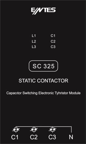
9 SC-325 Module Plate View SC-350 Module Plate View 8
10 SC-225/325 Terminal Plate View SC-250/350 Terminal Plate View 9

11 1- Shows that L1 phase voltage is at an acceptable level. 2- Shows that L2 phase voltage is at an acceptable level. 3- Shows that L3 phase voltage is at an acceptable level. 4- Shows that C1 capacitor is switched on. 5- Shows that C1 capacitor is switched on. 6- Shows that C1 capacitor is switched on. 10
12 1.6 Hardware Structure and Features SC-225/250 Block Diagramm SC-325/350 Block Diagramm 11
13 2 Device Utilization 2.1 Contents of Package 1 pc. SC-225/SC-250/SC-325/SC-350, 4 pcs. Panel mounting screw-nut set 4 pcs. Power terminal covers 1 pc. Installation template 1 pc. Metal handle 2 pcs. Handle installation screws User Manual 2.2 Operation of Device There are 4 models as below: SC-225: 25 KVAR with 2 Thyristors, SC-250: 50 KVAR with 2 Thyristors, SC-325: 25 KVAR with 3 Thyristors, SC-350: 50 KVAR with 3 Thyristors. SC-225/SC-250 models can be used only for the capacitors with triangle connection. SC-325/SC-350 models can be used only for the capacitors with star connection. 12
14 Static contactor switches the thyristors modules on or off according to the command it receives from the Power Factor Controller via Modbus or DC triggering. By adjusting the switch on time when the voltage on the capacitor and the voltage of the phase/phases that the capacitor connected to are equal, the static contactor limits the current value to a minimum during switching the capacitor on. Thus, capacitors can be switched on or off in a very short time period. The capacitor can be switched on in under a period (20 milliseconds) after the command is received from the relay. When the capacitors are not connected to the system, they are kept at a charged state at the peak value of the phase/phases that they are connected to. This ensures that the zero transfer occurs at the point on the sinus wave with the lowest gradient. If capacitor voltage remains at a higher value than the peak value for any reason (reactors may cause this), triggering is done at the peak value since there will be no equal values between peak value and capacitor voltage. Device contains a thermic protection. With this thermic protection, the capacitors are switched off when the temperature value exceeds a set value. Additionally, an external thermic can be connected. With this thermic, the capacitors can be switched off by setting the device to an alarm status. For example, you can connect the reactor thermic to this input. This input is isolated. 2.4 Installation 13
15 14
16 1. Earthing cable must be connected to the screw marked with Earth symbol. 2. Use 4 pieces of Metric-5 bolts for panel mounting. 3. Use panel mount template for panel holes. 4. Put the terminal covers in place. 5. Power cables must absolutely be connected with ferrules. 6. Make sure to leave at least 10 cm at the bottom and top for adequate cooling. 15
17 2.5 Electrical Connection SC-325/SC-350 CONNECTION DIAGRAM 16
18 SC-225/SC-250 CONNECTION DIAGRAM 17
19 2.6 Inputs and Outputs EXT: For connecting an external thermic. Triggering Inputs: It is used to switch the capacitors on with 5-30 VDC voltage. RS-485: It is used to switch the capacitors on through MODBUS-RTU protocol. Auxiliary supply: Supply voltage is connected to the device. Power Terminals: C1, C2, C3: Capacitors are connected. L1, L3: Phases are connected. N: For neutral connection. 3 Configuration 3.1 Utilization and Settings Device address can be set between 1 and 247 by using the 8 DIP switches located on the device. 1.Switch 2.Switch 3.Switch 4.Switch 5.Switch 6.Switch 7.Switch 8.Switch ON OFF Each one of the 8 switches has a value as given on the table above. Address is the summation of the numbers of DIP switches that are at ON position. If a wrong address is set (such as 0,, 248,, 255), device switches itself to alarm status and green LEDs blink while the red LEDs are switched off. On the table below, the switch positions for some example address values are given. 1.Switch 2.Switch 3.Switch 4.Switch 5.Switch 6.Switch 7.Switch 8.Switch 1 ON OFF OFF OFF OFF OFF OFF OFF 2 OFF ON OFF OFF OFF OFF OFF OFF 3 ON ON OFF OFF OFF OFF OFF OFF 23 0N ON ON OFF 0N OFF OFF OFF 247 0N 0N 0N OFF 0N 0N 0N 0N As seen from the table above, addresses like 3, 23 and 247 can be created like the examples below by adding the switch values together: 3 = =
20 247 = Coil Table SC-325/SC-350 için; ADDRESS(HEX) COIL R/W DA TRIGGERING R/W CHANNEL TRIGGER R CHANNEL TRIGGER R CHANNEL TRIGGER R CHANNEL ON/OFF R CHANNEL ON/OFF R CHANNEL ON/OFF R 0406 L1 VAR R 0407 L2 VAR R 0408 L3 VAR R 0409 THERMIC1 R 040A THERMIC2 R 040B THERMIC3 R 040C EXTERNAL THERMIC R 040D 1. EXTERNAL TRIGGER R 040E 2. EXTERNAL TRIGGER R 040F 3. EXTERNAL TRIGGER R Functıons of the device are used with the help of coils, which have been given their addresses on the table above. Triggering coils have been spread out to DA address range so that it can cover all channels of 247 devices with 3 channels. 4 coils have been reserved for each device. The first 3 are for the 3 channels. 4 th one is left empty. On models with 2 channels, coil of the 2 nd coil is also non-functional. This allows the triggering or the deactivating of the channels of all devices separately from each other with a single broadcast message. So in a single message, some capacitors can be switched on and some can be switched off. Other coils can t be reached this way. Triggering addresses; is calculated as (Device address - 1) * 4 + phase number -1. For example; (4 1) * = 12 is used to switch on the L2 phase of device number 4. (1 1) * = 0 is used to switch on the L1 phase of device number 1. 19
21 For the L3 phase of device number 247, the coil at the (247 1) * = 986 (0x03DA) address must be set to 1. Which coil addresses correspond to which channels of devices from 1 to 247 can be seen on the table below. First column shows the first 12 bits (000X-03DX) of the address. On the following columns, last 4 bits (XXX0-XXXF) of the address is shown. XXX0 XXX1 XXX2 XXX3 XXX4 XXX5 XXX6 XXX7 XXX8 XXX9 XXXA XXXB XXXC XXXD XXXE XXXF L1 L2 L3 L1 L2 L3 L1 L2 L3 L1 L2 L3 000X 1 EMPTY 2 EMPTY 3 EMPTY 4 EMPTY 001X 5 EMPTY 6 EMPTY 7 EMPTY 8 EMPTY 002X 9 EMPTY 10 EMPTY 11 EMPTY 12 EMPTY 003X 13 EMPTY 14 EMPTY 15 EMPTY 16 EMPTY 004X 17 EMPTY 18 EMPTY 19 EMPTY 20 EMPTY 005X 21 EMPTY 22 EMPTY 23 EMPTY 24 EMPTY 006X 25 EMPTY 26 EMPTY 27 EMPTY 28 EMPTY 007X 29 EMPTY 30 EMPTY 31 EMPTY 32 EMPTY 008X 33 EMPTY 34 EMPTY 35 EMPTY 36 EMPTY 009X 37 EMPTY 38 EMPTY 39 EMPTY 40 EMPTY 00AX 41 EMPTY 42 EMPTY 43 EMPTY 44 EMPTY 00BX 45 EMPTY 46 EMPTY 47 EMPTY 48 EMPTY 00CX 49 EMPTY 50 EMPTY 51 EMPTY 52 EMPTY 00DX 53 EMPTY 54 EMPTY 55 EMPTY 56 EMPTY 00EX 57 EMPTY 58 EMPTY 59 EMPTY 60 EMPTY 00FX 61 EMPTY 62 EMPTY 63 EMPTY 64 EMPTY 010X 65 EMPTY 66 EMPTY 67 EMPTY 68 EMPTY 011X 69 EMPTY 70 EMPTY 71 EMPTY 72 EMPTY 012X 73 EMPTY 74 EMPTY 75 EMPTY 76 EMPTY 013X 77 EMPTY 78 EMPTY 79 EMPTY 80 EMPTY 014X 81 EMPTY 82 EMPTY 83 EMPTY 84 EMPTY 015X 85 EMPTY 86 EMPTY 87 EMPTY 88 EMPTY 016X 89 EMPTY 90 EMPTY 91 EMPTY 92 EMPTY 017X 93 EMPTY 94 EMPTY 95 EMPTY 96 EMPTY 018X 97 EMPTY 98 EMPTY 99 EMPTY 100 EMPTY 019X 101 EMPTY 102 EMPTY 103 EMPTY 104 EMPTY 01AX 105 EMPTY 106 EMPTY 107 EMPTY 108 EMPTY 01BX 109 EMPTY 110 EMPTY 111 EMPTY 112 EMPTY 01CX 113 EMPTY 114 EMPTY 115 EMPTY 116 EMPTY 01DX 117 EMPTY 118 EMPTY 119 EMPTY 120 EMPTY 01EX 121 EMPTY 122 EMPTY 123 EMPTY 124 EMPTY 01FX 125 EMPTY 126 EMPTY 127 EMPTY 128 EMPTY 20
22 020X 129 EMPTY 130 EMPTY 131 EMPTY 132 EMPTY 021X 133 EMPTY 134 EMPTY 135 EMPTY 136 EMPTY 022X 137 EMPTY 138 EMPTY 139 EMPTY 140 EMPTY 023X 141 EMPTY 142 EMPTY 143 EMPTY 144 EMPTY 024X 145 EMPTY 146 EMPTY 147 EMPTY 148 EMPTY 025X 149 EMPTY 150 EMPTY 151 EMPTY 152 EMPTY 026X 153 EMPTY 154 EMPTY 155 EMPTY 156 EMPTY 027X 157 EMPTY 158 EMPTY 159 EMPTY 160 EMPTY 028X 161 EMPTY 162 EMPTY 163 EMPTY 164 EMPTY 029X 165 EMPTY 166 EMPTY 167 EMPTY 168 EMPTY 02AX 169 EMPTY 170 EMPTY 171 EMPTY 172 EMPTY 02BX 173 EMPTY 174 EMPTY 175 EMPTY 176 EMPTY 02CX 177 EMPTY 178 EMPTY 179 EMPTY 180 EMPTY 02DX 181 EMPTY 182 EMPTY 183 EMPTY 184 EMPTY 02EX 185 EMPTY 186 EMPTY 187 EMPTY 188 EMPTY 02FX 189 EMPTY 190 EMPTY 191 EMPTY 192 EMPTY 030X 193 EMPTY 194 EMPTY 195 EMPTY 196 EMPTY 031X 197 EMPTY 198 EMPTY 199 EMPTY 200 EMPTY 032X 201 EMPTY 202 EMPTY 203 EMPTY 204 EMPTY 033X 205 EMPTY 206 EMPTY 207 EMPTY 208 EMPTY 034X 209 EMPTY 210 EMPTY 211 EMPTY 212 EMPTY 035X 213 EMPTY 214 EMPTY 215 EMPTY 216 EMPTY 036X 217 EMPTY 218 EMPTY 219 EMPTY 220 EMPTY 037X 221 EMPTY 222 EMPTY 223 EMPTY 224 EMPTY 038X 225 EMPTY 226 EMPTY 227 EMPTY 228 EMPTY 039X 229 EMPTY 230 EMPTY 231 EMPTY 232 EMPTY 03AX 233 EMPTY 234 EMPTY 235 EMPTY 236 EMPTY 03BX 237 EMPTY 238 EMPTY 239 EMPTY 240 EMPTY 03CX 241 EMPTY 242 EMPTY 243 EMPTY 244 EMPTY 03DX 245 EMPTY 246 EMPTY 247 EMPTY BOŞ EMPTY 21
23 For SC-225/SC-250; ADDRESS(HEX) COIL R/W DA TRIGGERING R/W 0400 TRIGGER R CHANNEL ON/OFF R CHANNEL ON/OFF R 0403 L1 VAR R 0404 L3 VAR R 0405 THERMIC1 R 0406 THERMIC3 R 0407 EXTERNAL THERMIC R 0408 EXTERNAL TRIGGER R Triggering address is (device address 1) * 4. So, the coil at address 0 must be set to 1 to trigger the device at 1. address. On models with 2 channels, channels can t be triggered separately. 5 Troubleshooting When the red LEDs on the front panel of the device blink, it indicates that the triggering command has arrived from the relay but switching on couldn t be done for some reason. LEDs inform the user about these reasons as below: Green LEDs are switched on: External thermic error Green LEDs are switched off: Voltage error on the phase with its LED off Green LEDs blink: Device internal temperature error If red LEDs are switched on but green LEDs blink, it means that triggering signal is being created but thyristors can t switch. If this occurs, device must be immediately turned off and necessary controls must be done. 22
24 6 Help Headquarters: Yukarı Dudullu OSB 3. Cadde AND Sitesi No: Ümraniye, İstanbul / TR. Telephone: +90 (216) Fax: +90 (216) Fax (sales): +90 (216) İnternational sales: impex@entes.com.tr Domestic sales: satis@entes.com.tr Sister Companies Abroad ENTES B.V. / Hollanda Industrie Park Oost 3A, 5348 GM OSS THE NETHERLANDS Tel: Fax: info@entes.eu 23
Mounting Instructions / Manual MV1171
 Mounting Instructions / Manual MV1171 POWER FACTOR Controller ESTAmat MH-N Vishay Electronic GmbH ESTA Capacitors Division Revision: 19-April-2011 Hofmark-Aich-Strasse 36 84030 Landshut, Germany Phone
PM-311x Quick Start Ver PM-311x introduction 1.1. Caution & Warning 1.2. Product Warranty & Customer Support
 PM-311x Quick Start Ver. 1.1 1. PM-311x introduction ICP DAS brings the most powerful, cost-effective, advanced Smart Power Meters PM-3000 series that gives you access to real-time electric usage for single-phase
FCR 06, FCR 12. Power factor correction controller. User and service manual
 FCR 06, FCR 12 Power factor correction controller User and service manual version 2.3 Czech Republic Czech Republic 1 Content 1. Control and signal elements... 3 2. Device description... 4 3. Instruction
Computer-14d - xx - 144a
 POWER FACTOR REGULATOR Computer-14d - xx - 144a INSTRUCTION MANUAL ( M 981 602 / 98B ) (c) CIRCUTOR S.A. -------- POWER FACTOR REGULATOR COMPUTER- 14d --------- Page 2 1.- POWER FACTOR REGULATORS COMPUTER-14d-144a
INSTRUCTION MANUAL. Power Factor Controller - 12 steps Model A12 NOKIAN CAPACITORS. Power Factor Controller A12
 INSTRUCTION MANUAL Power Factor Controller - 12 steps Model A12 NOKIAN CAPACITORS Power Factor Controller A12 1. CONTENTS 1. CONTENTS 1 2. FEATURES 2 3. INSTALLATION, CONNECTION AND APPLYING POWER 2 4.
VFSC9 ELECTRONIC SPEED CONTROLLER. Mounting and operating instructions
 ELECTRONIC SPEED CONTROLLER Mounting and operating instructions Table of contents SAFETY AND PRECAUTIONS 3 PRODUCT DESCRIPTION 4 ARTICLE CODES 4 INTENDED AREA OF USE 4 TECHNICAL DATA 4 STANDARDS 5 WIRING
Commissioning Instructions Rev. 03
 Power Factor regulator BLR-CM-T/RT L1 L2 L3 Einspeisung Supply Last Load BLR-CM-T + - Triggereingang/ Triggerinput BEL-TSXX N PE L1 L2 L3 Einspeisung Supply Last Load BLR-CM-RT + - Triggereingang/ Triggerinput
Reactive Power Control Relay RM 2106 / 2112 Operating Instructions. FRAKO Kondensatoren- und Anlagenbau
 Reactive Power Control Relay RM 2106 / 2112 Operating Instructions FRAKO Kondensatoren- und Anlagenbau www.frako.com Figure 1 Front view a b c d e Display for active capacitor stages Display for inductive
Power factor correction and harmonic filtering. Automatic power factor regulators
 Power factor correction and harmonic filtering Automatic power factor regulators Automatic power factor reguladors R.1 - Automatic power factor regulators Selection table R1-4 computer Plus-T Intelligent
ERV-M ELECTRONIC FAN SPEED CONTROLLER. Mounting and operating instructions
 ELECTRONIC FAN SPEED CONTROLLER Mounting and operating instructions Table of contents SAFETY AND PRECAUTIONS 3 PRODUCT DESCRIPTION 4 ARTICLE CODES 4 INTENDED AREA OF USE 4 TECHNICAL DATA 4 STANDARDS 5
Wireless multizone receiver RDE-MZ6
 s 1 428 Wireless multizone receiver RDE-MZ6 for floor heating / zone heating systems Mains-powered RDE-MZ6 multizone wireless receiver (AC 230 V) DIN rail mounting 2-position control with On/Off output
sw rev. 55B DEVICE FOR THE PERMANENT CONTROL OF INSULATION ON THE SUPPLY LINES IN MEDICAL PRACTICE PLACES INSTALLATIONS
 INSTRUCTIONS MANUAL IM831-U v0.92 HRI-R40W sw rev. 55B DEVICE FOR THE PERMANENT CONTROL OF INSULATION ON THE SUPPLY LINES IN MEDICAL PRACTICE PLACES INSTALLATIONS INDEX: GENERAL TYPES ACESSORIES AND OPTIONS
Low Voltage Power Factor Correction Equipment Specifications Automatic, Automatic Detuned, Automatic Tuned
 Low Voltage Power Factor Correction Equipment Specifications Automatic, Automatic Detuned, Automatic Tuned Part 1 - General Scope and Product Description 1.0 This specification contains the minimum design
Installation and Operating Instructions. Power IT Power Factor Controller RVC
 Installation and Operating Instructions Power IT Power Factor Controller RVC Table of contents Page 1. Read this first... 3 About this Instruction Manual... 3 Safety... 3 Electromagnetic compatibility...
Room Temperature Controllers. for heating and cooling systems
 3 048 RCU15 Room Temperature Controllers for heating and cooling systems RCU15 Choice of two-position or modulating PI control ON / OFF or PWM outputs for heating and cooling Control depending on room-
Onsite Mobile AC High Voltage Test System
 TSGMF(T) series Onsite Mobile AC High Voltage Test System Onsite mobile AC high voltage test systems are used for withstand voltage testing, partial discharge measurement, tan delta measurement to instrument
D.C. BRUSHLESS MOTORS DRIVE. BLD07-IT Service Manual
 D.C. BRUSHLESS MOTORS DRIVE BLD07-IT Service Manual INTECNO s.r.l. Via Caduti di Sabbiuno n. 9/E 40011 Anzola Emilia (BO) - Italy tel. 051.19985350 fax 051.19985360 www.intecno-srl.com INDEX Description
GFL-1000 User Manual Ground Fault Locator
 GFL-Series User Manual V1.1 GFL-1000 User Manual Ground Fault Locator Contents Contents... 1 1 Declaration of Conformity... 3 2 Introduction... 3 3 Equipment Information... 3 3.1 Safety Precautions...
ITP14. Universal process indicator. User guide
 ITP14 Universal process indicator User guide ITP14_2018.05_0279_EN All rights reserved Subject to technical changes and misprints akytec GmbH Vahrenwalder Str. 269 A 30179 Hannover Germany Tel.: +49 (0)
Installation guide 971 SmartRadar LTi
 Installation guide 971 SmartRadar LTi March 2009 Part no. 4416.715 Revision 3 Enraf B.V. P.O. Box 812 2600 AV Delft Netherlands Tel. : +31 15 2701 100 Fax : +31 15 2701 111 E-mail : enraf-nl@honeywellenraf.nl
USER MANUAL. DC 13kHz High Voltage Amplifier WMA V to +175V output. Stable with all capacitive loads, generates no overshoot
 DC 13kHz High Voltage Amplifier WMA-02 www.falco falco-systems systems.com USER MANUAL -175V to +175V output DC to 13kHz at -3dB full power bandwidth single power supply 24V 30V DC, battery power possible
Owner s Manual S10 SERIES ELECTRONIC STEP CONTROLLER WITH VERNIER CONTROL
 Owner s Manual S10 SERIES ELECTRONIC STEP CONTROLLER WITH VERNIER CONTROL This manual covers installation, setup, operation and troubleshooting. Read carefully before attempting to install, operate or
ADC5000 SERIES. AC/DC Switch Mode Power Supplies and Rectifiers for Industrial and Telecom Applications. 60W, 125W and 250 W
 ADC5000 SERIES AC/DC Switch Mode Power Supplies and Rectifiers for Industrial and Telecom Applications 60W, 125W and 250 W Input voltage 230/115 VAC voltages 12, 24, 36 or 48 VDC Statistical MTBF >3 000
ISOMETER IRDH575. Approvals
 Insulation monitoring device for unearthed AC, DC and AC/DC systems (IT systems) with control and display function for EDS insulation fault location systems IRDH575_D00089_02_D_XXEN/09.2018 Insulation
VIP Current & Power Multimeter
 VIP Current & Power Multimeter Rev 1.6 Table of Contents 1. Mechanical Installation... 3 2. Wiring diagram... 4 3. Specifications... 5 Technical Specifications... 5 3.2 Measuring Specifications... 5 4.
USER S MANUAL. Rail-mounted temperature transmitter ATL
 IO.ATL (ENG) USER S MANUAL Rail-mounted temperature transmitter ATL APLISENS S.A., 03-192 Warszawa, ul. Morelowa 7 tel. +48 22 814 07 77; fax +48 22 814 07 78 www.aplisens.pl, e-mail: aplisens@aplisens.pl
maxon document number:
 maxon document number: 791272-04 1 Table of contents... 2 2 Table of figures... 3 3 Introduction... 4 4 How to use this guide... 4 5 Safety Instructions... 5 6 Performance Data... 6 6.1 Motor data... 6
Integra 1560 and 1580 Digital Transducer Systems
 Integra 1560 and 1580 multi function transducers provide high accuracy
HAWK5000 Operators Manual
 HAWK5000 Operators Manual Keison Products P.O. Box 2124, Chelmsford CM1 3UP, England Tel: +44 (0) 1245 600560 Fax: +44 (0) 1245 600030 Email: sales@keison.co.uk www.keison.co.uk KANE INTERNATIONAL LIMITED
ENA33LCD. Power line analyzer. User and service manual. Obrezija 5 SI-1411 Izlake
 ENA33LCD Power line analyzer User and service manual version 2.9 (FW version 6.8 and newer) ETI, d.o.o. Obrezija 5 SI-1411 Izlake www.etigroup.eu/products-services 1. Front control panel and terminal plate
Capacitor Switching Contactors
 Capacitor Switching D385E51 Technical catalogues and news under: www.benedict.at Motor-Starter Mini- Overload Relays Capacitor Switching Motor-Starters Modular Circuit Breakers M4-32T... up to 32A M4-32R..
PLA 33. Power line analyzer. User and service manual. version 2.4
 PLA 33 Power line analyzer User and service manual version 2.4 Content. Front control panel and terminal plate...3 7.2.2. System frequency setting...0 2. Device description...4 7.2.3. Password protection...0
Series P. Applications
 Ratings 25 800 VA Voltage Primary 230 / 400 / 460 V range Secondary 6 / 12 V 12 / 24 V 24 / 48 V 115 / 230 V Voltage selection by means of metal connection bridges, offering the full rated power at any
Installation & Operation Manual ELNet VIP
 Installation & Operation Manual ELNet VIP Electrical Measurements Table of Contents 1. Mechanical Installation... 1-3 2. Wiring diagram... 2-5 3. Specifications... 3-6 Technical Specifications... 3-6 Measuring
Room Temperature Controllers. for heating and cooling systems
 3 041 RCU10 RCU101 Room Temperature Controllers for heating and cooling systems RCU10 Choice of two-position or modulating PI control ON / OFF or PWM outputs for heating and cooling Operating modes: normal
Power factor correction and harmonic filtering. Automatic power factor regulators R.1
 Power factor correction and harmonic filtering Automatic power factor regulators R.1 R.1 Automatic power factor regulators R.1 - Automatic power factor regulators Selection table R1-4 computer Plus-T Intelligent
POWER AMPLIFIER. Owner s Manual Mode d emploi Bedienungsanleitung Manual de instrucciónes CLIP SIGNAL TEMP PROTECTION POWER
 POWER AMPLIFIER Owner s Manual Mode d emploi Bedienungsanleitung Manual de instrucciónes TEMP PROTECTION POWER A CLIP SIGNAL B ON OFF M Introduction Thank you for purchasing a Yamaha C450/320/160 series
DPF-MAC Auto power factor controller
 Digital Electric& Electronics System DPF-MAC Auto power factor controller MULTI POWER FACTOR AUTOMATIC MULTI POWER FACTOR AUTOMATIC Introduction DPF-MAC increases usage efficiency by controlling the power
SGMF(T) series. Onsite Mobile AC High Voltage Test System. Applications:
 series. Onsite Mobile AC High Voltage Test System. Applications:") SGMF(T) series Onsite Mobile AC High Voltage Test System On-site AC high voltage test systems are used for voltage withstanding test, partial discharge measurement, tan delta measurement on those instrument
SGMF(T) series Onsite Mobile AC High Voltage Test System On-site AC high voltage test systems are used for voltage withstanding test, partial discharge measurement, tan delta measurement on those instrument
PEAKTRONICS AMI-103. AC Motor Interface AMI-103 AMI-103A AMI-103B FEATURES
 PEAKTRONICS The Peaktronics AC Motor Interface is used to interface common electrical control signals to AC actuators. The unit provides the motor drive circuits, protection circuits, and isolation between
MU110-16R(K) Digital output module 16 channel. User guide
 Digital output module 16 channel. User guide") MU110-16R(K) Digital output module 16 channel User guide MU110-16R(K)_2016.12_0220_EN All rights reserved Subject to technical changes and misprints akytec GmbH Vahrenwalder Str. 269 A 30179 Hannover Germany
MU110-16R(K) Digital output module 16 channel User guide MU110-16R(K)_2016.12_0220_EN All rights reserved Subject to technical changes and misprints akytec GmbH Vahrenwalder Str. 269 A 30179 Hannover Germany
BU: EPBP GPG: DIN Rail Products Devices for the permanent control of insulation on supply lines for medical locations ISOLTESTER-DIG-RZ/RS/PLUS
 INSTRUCTION MANUAL BU: EPBP GPG: DIN Rail Products Devices for the permanent control of insulation on supply lines for medical locations ISOLTESTER-DIG-RZ/RS/PLUS 1/23 More information than that reported
Overtravel of 3.5 mm max. Power source DC D5C-1DS0 D5C-1DP0 D5C-1DA0 AC D5C-1AS0 D5C-1AP0 D5C-1AA0 Antenna only D5C-00S0 D5C-00P0 D5C-00A0
 Touch Switch Unique 18 mm Capacitive Touch Switch with Choice of Three Actuators is Activated with Only a Very Slight Physical Contact Lightweight objects, such as thin wire or foil can be accurately detected.
ITP16. Temperature indicator. User guide
 ITP16 Temperature indicator User guide ITP16_2018.05_0280_EN All rights reserved Subject to technical changes and misprints akytec GmbH Vahrenwalder Str. 269 A 30179 Hannover Germany Tel.: +49 (0) 511
SRA 2250/6 RESISTOR ARS-01 RESISTOR AUTOMATICS
 ELECTRICAL ENGINEERING DIVISION Distribution Network Department SRA 2250/6 RESISTOR ARS-01 RESISTOR AUTOMATICS ELA T150.2 en SRA 2250/6 Resistor specification The SRA 2250/6 Resistor is intended to increase
ADA User manual ADA Multimode Fibre-Optic to Current Loop Converter
 User manual Multimode Fibre-Optic to Converter Copyright 2001-2017 CEL-MAR sp.j. 1 io_ada-7021_v1.02_en Contents 1.GENERAL INFORMATION... 3 1.1.WARRANTED INFORMATION... 3 1.2.GENERAL CONDITIONS FOR SAFE
Room Temperature Controllers. for heating and cooling systems
 3 041 RCU10 RCU10.1 Room Temperature Controllers for heating and cooling systems RCU10... Choice of two-position or modulating PI control ON / OFF or PWM outputs for heating and cooling Operating modes:
Starbox. Installation guide
 Starbox Installation guide Introduction Welcome The Starbox is a wiring centre that allows ican networks to be wired in a star topology (as an alternative to the standard daisy-chain topology). The Starbox
Circuit Analyzer MS5908A. Operation S Manual MS5908A TEST. ma VA ms Hz% 12 A 15 A 20 A HOLD ms VA. V Vd Z RCD GFCI
 Circuit Analyzer Operation S Manual MS5908A L - N L - E N - E Peak Z - L Z - N Z - E ASCC AC TEST N[] [] L E ma VA ms Hz% 12 A 15 A 20 A HOLD ms VA Ω% V Vd Z RCD GFCI MS5908A General Instructions This
TE200S Solid State Relays. Two-phase control of three-phase loads. User manual
 TE200S Solid State Relays Two-phase control of three-phase loads User manual Copyright Eurotherm Automation 1998 All rights reserved. All reproduction or transmission in any form or using any procedure
DEIF A/S. Insulation monitor. Type SIM-Q
 Insulation monitor 4921232C Monitoring of insulation resistance on ungrounded AC networks (IT network) Working voltage up to 69V AC, withstands up to V DC Measuring range 1...Mohm or 1...Mohm Alarm on
Index. Capacitor Switching - 2 Contactors. Typical Circuit Diagram 2. Auxiliary Contact Blocks 2. Contactors 3. Dimensions 3. Technical Data 4,5,6
 Index Index Page Capacitor Switching - 2 Contactors Typical Circuit Diagram 2 Auxiliary Contact Blocks 2 Contactors 3 Dimensions 3 Technical Data 4,5,6 Contactor operation 7 Function 8 Construction 9 Oscillogram
Installation Guide Multi Position Servo Controller E1100-MP and E1100-MP-HC
 Installation Guide Multi Position Servo Controller E00-MP and E00-MP-HC Content IMPORTANT NOTES FOR E00 SERIES CONTROLLERS 2 SYSTEM OVERVIEW 3 E00-MP SERIES FUNCTION AND WIRING 4 E00-MP-HC SERIES FUNCTION
AC 01.2 Modbus TCP/IP
 General information Actuator controls AC 01.2 for controlling multi-turn actuators of the SA/SAR.2 type range and part-turn actuators of the SQ/SQR.2 type range with interface. Features and functions Power
SUPPLY NETWORK ANALYZER CVM-96 SERIES
 SUPPLY NETWORK ANALYZER CVM-96 SERIES (Power Demand) INSTRUCTION MANUAL ( M 981 326 / 00B - GB) (c) CIRCUTOR S.A. ----- Supply network analyzer CVM-96 ------ User's manual --- Page No. 1 CVM-96 SUPPLY
WRM-10 TM TRANSFORMER WINDING RESISTANCE METER
 WRM-10 TM TRANSFORMER WINDING RESISTANCE METER USER S MANUAL Vanguard Instruments Company, Inc. 1520 S. Hellman Ave. Ontario, California 91761, USA TEL: (909) 923-9390 FAX: (909) 923-9391 June 2009 Revision
ProfiScale MULTI Multimeter
 1,5 V 9V 200 mv 600 V 200 ma 1/10 A ProfiScale MULTI Multimeter en Operating instructions BURG-WÄCHTER KG Altenhofer Weg 15 58300 Wetter Germany Introduction Want the reassurance of knowing whether current
INSTRUCTIONS MANUAL DEVICE FOR THE PERMANENT CONTROL OF INSULATION ON THE SUPPLY LINES IN MEDICAL PRACTICE PLACES INSTALLATIONS HRI-R40W
 Page 2 / 16 INDEX: GENERAL TYPES ACESSORIES AND OPTIONS INSTALLATION WIRING DIAGRAMS CONNECTING TERMINALS DIAGRAMS WIRING DIAGRAM DESCRIPTION WORKING DESCRIPTION AND KEYBOARD WORKING DESCRIPTION AND PROGRAMMING
OPERATING MANUAL SERIES R B F BRUSHLESS RACK SYSTEM
 OPERATING MANUAL SERIES R B F BRUSHLESS RACK SYSTEM Version 3.0 (European version 1.3) This is a general manual describing a series of racks receiving Servo Amplifiers having output capability suitable
Temperature Input Module for Zone 1 Series 9482/32
 www.stahl.de > 8 channels for temperature sensors > Intrinsically safe inputs Ex ia > For Pt-, Ni- and Cu-resistance temperature detectors according to DIN, IEC and GOST in 2-, 3- and 4-wire circuits >
Motorised unit Changeover switch installation and operation guide. Ref. 4257Z001 Rev. 05
 Ref. 4257Z001 Rev. 05 Motorised unit Changeover switch installation and operation guide Edition September 2007 Index Please follow carefully the instructions included in this manual for a correct installation
KEY FEATURES. Selectable modes of control : Phase Angle or Burst Fire (Single- Cycle/Dual-Cycle & adjustable STD Burst Firing)
") X20092 DMFC36 Issue: 2 User manual Date: 31/10/14 Page: 1 of 10 KEY FEATURES Standard DIN Rail Mounting Selectable modes of control : Phase Angle or Burst Fire (Single- Cycle/Dual-Cycle & adjustable STD
X20092 DMFC36 Issue: 2 User manual Date: 31/10/14 Page: 1 of 10 KEY FEATURES Standard DIN Rail Mounting Selectable modes of control : Phase Angle or Burst Fire (Single- Cycle/Dual-Cycle & adjustable STD
RUDOLF Digital power analyzer. Advanced Version
 RUDOLF Digital power analyzer Advanced Version Digital power analyzer Advanced Version Company Introduction Bridex Singapore Pte Ltd is founded in 1978 as a manufacturer of instruments transformer for
8V General information. 2 Order data 8V
 8V05.00-8V05.00- General information Modular mechanical design using plug-in modules Integrated line filter Integrated braking resistor All connections are made using plug-in connectors Integrated electronic
RSMFX-2R MULTIFUNCTIONAL
 Mounting and operating instructions Table of contents SAFETY AND PRECAUTIONS 3 PRODUCT DESCRIPTION 4 ARTICLE CODES 4 INTENDED AREA OF USE 4 TECHNICAL DATA 4 STANDARDS 4 OPERATIONAL DIAGRAMS 5 WIRING AND
Energy Management Energy Meter Type EM21 72R Retro-Fit
 Energy Management Energy Meter Type EM21 72R Retro-Fit Including 3 miniature split-core current sensors 10mm (90A), 16mm (150A) and 24mm (250A) diameter holes Class A (kwh) according to EN50470-3 Class
USER MANUAL SATEL i-link I/O-converter Version 1.6
 USER MANUAL SATEL i-link I/O-converter Version 1.6 TABLE OF CONTENTS TABLE OF CONTENTS... 2 IMPORTANT NOTICE... 3 PRODUCT CONFORMITY... 4 WARRANTY AND SAFETY INSTRUCTIONS... 5 1 GENERAL... 6 1.1 SATEL
8V General information. 2 Order data 8V
 8V80.00-8V80.00- General information Modular mechanical design using plug-in modules Integrated line filter Integrated or optional external braking resistor All connections are made using plug-in connectors
JBUS/MODBUS communication card
 JBUS/MODBUS communication card JBUS/MODBUS Installation and user manual 66061 51029066EN/BF - Page 1 Page 2-51029066EN/BF Introduction Thank you for selecting an APC by Schneider Electric product to protect
AZ Series. Function Edition. Closed Loop Stepping Motor and Driver Package. Operation. I/O signals. Parameter
 HM-6262 Closed Loop Stepping Motor and Driver Package Operation I/O signals Parameter AZ Series Function Edition Method of control via Modbus RTU (RS-485 communication) Method of control via industrial
USER MANUAL XLB-2500 Short Arc Xenon Lamp Ballast
 USER MANUAL XLB-2500 Short Arc Xenon Lamp Ballast The XLB-2500 Xenon lamp ballast is a very compact power supply designed for OEM applications. The XLB-2500 is ideal for high power applications where economy
With Audible Detect Signal
 T-100 SERIES SINGLE CHANNEL SHELF MOUNT DETECTOR Meets and exceeds NEMA TS 1 specification. Six front panel DIP switches provide: Seven levels of sensitivity plus off. Presence or Pulse mode. Four loop
Monitoring Electric Network Via Internet
 Monitoring Electric Network Via Internet NETWORK ANALYSER let "it" analyse! MPR63 Real time monitoring via internet / intranet Measurement of all electrical parameters Including Harmonics Automatic recording
AC/DC Power Supply Series APPLICATION NOTE
 -350 + -700 AC/DC Power Supply Series APPLICATION NOTE NV350_NV700 App notes 69498 12.doc Document Number 69498 Page 1 of 17 1. INPUT... 3 AC INPUT LINE REQUIREMENTS... 3 2. DC OUTPUT... 3 OUTPUT VOLTAGES...
TCS2P125. Automatic Transfer Switch Control Unit for 1 Phase System Operation Manual
 TCS2P125 Automatic Transfer Switch Control Unit for 1 Phase System Operation Manual Single Phase 2P 125 Amp Rated Voltage 250 Vac Patent Number : U.S. Pat. No. 7,557,683 KUTAI ELECTRONICS INDUSTRY CO.,
Technical Manual. Standard Communication Protocol TA3840C
 TA3840C Technical Manual SAS au Capital de 2 158 244-444 871 933 R.C.S. Bourges - APE : 2651B Headquarter : 9, rue Isaac Newton - 18000 Bourges - France Technical Manual TA3840C 1 st Edition Released February
AC CURRENT GENERATOR POC-6000 (current from 0 to 1000 ARMS)
") AC CURRENT GENERATOR PERFORMANCES Wide range of current 50 db dynamic range Signal-to-noise ratio: 80 db open loop protection Stability < 0,1% Very low THD distortion < 0,3% External synchronization Build-up
AC CURRENT GENERATOR PERFORMANCES Wide range of current 50 db dynamic range Signal-to-noise ratio: 80 db open loop protection Stability < 0,1% Very low THD distortion < 0,3% External synchronization Build-up
LV Compensation & Filtering Products
 GE Grid Solutions LV Compensation & Filtering Products Providing Power Quality and Energy Efficiency Low (LV) reactive power compensation and harmonic filtering solutions help customers to improve the
DIN Rail Kilowatt Hour Energy Meters
 DIN Rail Kilowatt Hour Energy Meters Single Phase DIN Rail Kilowatt Hour Energy Meters DRK-1PPO-240 Single Phase 230V - 15A Direct Connected, Pulse Output This innovative two DIN module kilowatt hour energy
AC/DC Power Supply Series APPLICATION NOTE
 -175 AC/DC Power Supply Series APPLICATION NOTE 69493 NV175 App note 6a.doc Document Number 69493 Page 1 of 20 1. INPUT... 4 AC INPUT LINE REQUIREMENTS... 4 2. DC OUTPUT... 4 OUTPUT VOLTAGES all models
PEAKTRONICS AMC-103 ADDITIONAL FEATURES. AC Motor Controller, 2A AMC-103 AMC-103A AMC-103B
 PEAKTRONICS The Peaktronics AC Motor Controller is a compact module that is intended for controlling small AC actuator motors of up to 2A. The is very well suited for applications where space constraints
DESCRIPTION DIMENSIONS HOW TO ORDER
 ELECTRONIC CONTROLLER: C102X1000 OR MODULATING ELECTRIC HEAT APPLICATIONS 0 to 10 VDC modulating output VDC pulsed modulating output Room or supply control applications DESCRIPTION DIMENSIONS The C102X1000
Excitation Systems THYRIPART. Compound-Excitation System for Synchronous Generators. Power Generation
 Excitation Systems Compound-Excitation System for Synchronous Generators Power Generation Operating Characteristics Load dependent Short circuit supporting Low voltage gradient dv/dt Black start capability
MID. Energy Management Energy Meter Type EM23 DIN. Product Description. Type Selection. How to order EM23 DIN AV9 3 X O1 PF A EM23 DIN
 Energy Management Energy Meter Type EM23 DIN Certified according to MID Directive (option PF only): see how to order below Other version available (not certified, option X): see how to order on the next
SYNCHRONISM RELAY SYNCRO-96. (Code ) INSTRUCTION MANUAL ( M / 99A ) (c) CIRCUTOR S.A.
 INSTRUCTION MANUAL ( M / 99A ) (c) CIRCUTOR S.A.") SYNCHRONISM RELAY SYNCRO-96 (Code 2 28 913-2 28 914-2 28 915) INSTRUCTION MANUAL ( M 981 196 / 99A ) (c) CIRCUTOR S.A. ----- Synchronism relay SYNCRO-96 -------- M - 981 196 --- Page nº 1 Synchronism relay
SYNCHRONISM RELAY SYNCRO-96 (Code 2 28 913-2 28 914-2 28 915) INSTRUCTION MANUAL ( M 981 196 / 99A ) (c) CIRCUTOR S.A. ----- Synchronism relay SYNCRO-96 -------- M - 981 196 --- Page nº 1 Synchronism relay
Temperature Controller model MFC-301/T-Dry. Version for Dry Transformers and Motors. Technical Manual. Licht
 Temperature Controller model MFC-301/T-Dry Version for Dry Transformers and Motors Technical Manual Licht Contents 1 Introduction 2 2 Operating principle 3 2.1 General principle 3 2.2 RTD operation 3 3
FL ballasts Electronic dimming. PCA T5 ECO lp Y, 3x14/24 W and 4x14/24 W ECO T5
 T5 PCA T5 ECO lp Y, x1/ W and x1/ W ECO T5 Product description Processor-controlled ballast with y inside Highest possible energy class CELMA EEI = A1 BAT 1 Noise-free precise control via DSI signal, switchdim
FL ballasts Electronic dimming. PCA T8 ECO lp Y II, W ECO T8
 T8 PCA T8 ECO lp Y II, 18 58 W ECO T8 Product description Processor-controlled ballast with y II inside Highest possible energy class CELMA EEI = A1 BAT 1 Noise-free precise control via DALI or DSI signal,
Commissioning and Maintenance of Power Factor Correction Systems
 Dear Customer, We would like to thank you for choosing a power factor correction system from FRAKO Kondensatoren- und Anlagenbau GmbH. It is a pleasure to welcome you into the ever-expanding circle of
400,440Vac Vdc V, A, W, VA, var, Hz, V, Avg. A cos phi, sin phi and phi measurement kwh, kvarh (via Pulse Output)
") MODEL EM4000ACF Multifunction Transducer for alternating voltage and current Power supply voltages: Suitable for DIN-rail mounting 85 240Vac 400,440Vac 24 65Vdc 100..330Vdc V, A, W, VA, var, Hz, V, Avg.
MODEL EM4000ACF Multifunction Transducer for alternating voltage and current Power supply voltages: Suitable for DIN-rail mounting 85 240Vac 400,440Vac 24 65Vdc 100..330Vdc V, A, W, VA, var, Hz, V, Avg.
R24 DISPLAY MODULE WITH ACTIVE OUTPUT AND RELAY
 Čapkova 22 678 01 Blansko tel.: +420 516 416942, 419995 fax: +420 516 416963 R24 DISPLAY MODULE WITH ACTIVE OUTPUT AND RELAY Display module is designed for measuring the resistance, the signal from the
These power supplies are ideal for medical, telecom, datacom, industrial equipment and other applications.
 The MBC75 Series of open frame medical power supplies feature a wide universal AC input range of 85 V 264 VAC, offering 75 W of output power in a compact footprint, with a variety of isolated single output
JBus/Modbus Communication Card
 JBus/Modbus Communication Card Installation and Operation 05/2018 www.schneider-electric.com Legal Information The Schneider Electric brand and any registered trademarks of Schneider Electric Industries
PEM353. Universal measuring device
 353 Universal measuring device 353_D00335_00_D_XXEN/06.2018 353 Universal measuring device Product description The digital universal measuring device 353 is used to record and display measured quantities
PROFIBUS HUB REPEATER
 USER S MANUAL PROFIBUS HUB REPEATER RHP303 R H P 3 0 3 M E smar www.smar.com Specifications and information are subject to change without notice. Up-to-date address information is available on our website.
MASTECH MS5908. Circuit Analyzer
 MASTECH MS5908 Circuit Analyzer Operation Manual 2 General Instructions This circuit analyzer is a special test device designed for AC low-voltage distribution line quick fault location. With simple operation,
MU110-8R(K) Digital output module 8 channel. User guide
 Digital output module 8 channel. User guide") MU110-8R(K) Digital output module 8 channel User guide MU110-8R(K)_2019.01_0296_EN All rights reserved Subject to technical changes and misprints akytec GmbH Vahrenwalder Str. 269 A 30179 Hannover Germany
MU110-8R(K) Digital output module 8 channel User guide MU110-8R(K)_2019.01_0296_EN All rights reserved Subject to technical changes and misprints akytec GmbH Vahrenwalder Str. 269 A 30179 Hannover Germany
ALPTEC POWER FACTOR CONTROLLER
 ALPTEC POWER FACTOR CONTROLLER ALPTEC3 ALPTEC5 ALPTEC7 ALPTEC12 0 REF : 2008-ALPTEC3.5.7.12-01-ANG CONTENTS I GENERAL INFORMATION. 2 II WAYS TO SET UP THE CONTROLLER.. 4 III OPERATING MODE..6 IV ADVANCED
02/11/2015
 Modem communication plug and play solutions GSM Part number 88970119 For remote control of your application Automatic notification of alarms via SMS (GSM Modem) / email or on a PC with M3 ALARM software.
AC/DC Power Supply Series APPLICATION NOTE
 -175 AC/DC Power Supply Series APPLICATION NOTE 69493 NV175 App note 4.doc Document Number 69493 Page 1 of 17 1. INPUT...3 AC INPUT LINE REQUIREMENTS... 3 2. DC OUTPUT...3 OUTPUT VOLTAGES... 3 REMOTE SENSE...