USER MANUAL SATEL i-link I/O-converter Version 1.6
|
|
|
- Conrad Stevenson
- 5 years ago
- Views:
Transcription

1 USER MANUAL SATEL i-link I/O-converter Version 1.6
2 TABLE OF CONTENTS TABLE OF CONTENTS... 2 IMPORTANT NOTICE... 3 PRODUCT CONFORMITY... 4 WARRANTY AND SAFETY INSTRUCTIONS GENERAL SATEL I-LINK PULSE COUNTER AND I/O -CONVERTER SPECIFICATIONS FUNCTIONS... 8 SCREW CONNECTOR FUNCTIONS SUPPLY VOLTAGE, 9 30 VDC ALARM OUTPUT, AL OUT OUT DIGITAL INPUTS, I1, I2, AND OUTPUTS O1, O PULSE INPUT INDICATORS DIP-SWITHCES DIP -switches, 8 pcs Address selection table Channel selection table OPERATION POINT- TO-POINT Updating Digital messages Start of the Point-to-Point operation POINT-TO-MULTIPOINT Start of the Multipoint operation FACTORY SETTINGS CONNECTION EXAMPLES ACCESSORIES
3 IMPORTANT NOTICE All rights to this manual are owned solely by SATEL Oy permission from the owner of the rights by printing, copying, recording or by any other means or the full or partial translation of the manual to any other language including all programming languages using any electrical, mechanical, magnetic, optical, manual or other methods or devices is forbidden. SATEL reserves the right to change the technical specifications or functions of its products or to discontinue the manufacture of any of its products or to discontinue the support of any of its products without any written announcement and urges its customers to ensure, that the information at their disposal is valid. SATEL software and programs are delivered as is. The manufacturer does not grant any kind of warranty including guarantees on saleability and guarantees pertaining to applicability to a certain application. Under no circumstances is the manufacturer or the developer of a program responsible for any possible damages caused by the use of a program. The names of the programs as well as all copyrights relating to the programs are the sole property of SATEL. Any transfer, licensing to a third party, leasing, renting, transportation, copying, editing, translating, modifying into another programming language or reverse engineering for any intent is forbidden without the written consent of SATEL. SATEL PRODUCTS HAVE NOT BEEN DESIGNED, INTENDED NOR INSPECTED TO BE USED IN ANY LIFE SUPPORT RELATED DEVICE OR SYSTEM RELATED FUNCTION NOR AS A PART OF ANY OTHER CRITICAL SYSTEM AND ARE GRANTED NO FUNCTIONAL WARRANTY IF THEY ARE USED IN ANY OF THE APPLICATIONS MENTIONED. 3
4 PRODUCT CONFORMITY SATEL i-link Hereby, SATEL Oy declares that SATEL i-link converters are in compliance with the essential requirements and other relevant provisions of Directive 89/336/EEC. Therefore the equipment is labelled with the following CE-marking
5 WARRANTY AND SAFETY INSTRUCTIONS Read these safety instructions carefully before using the product: Warranty will be void, if the product is used in any way, which is in contradiction with the instructions given in this manual, or if the housing of the radio modem has been opened or tampered with. The radio modem is to be used only on frequencies allocated by local authorities and without exceeding the given maximum allowed output power ratings. SATEL Oy is not responsible, if any products manufactured by it are used in unlawful ways. The devices mentioned in this manual are to be used only according to the instructions described in this manual. Faultless and safe operation of the devices can be guaranteed only if the transport, storage, operation and handling of the devices are appropriate. This also applies to the maintenance of the products. To prevent damage both the radio modem and any terminal devices must always be switched OFF before connecting or disconnecting the serial connection cable. It should be ascertained that different devices used have the same ground potential. Before connecting any power cables the output voltage of the power supply should be checked. Salo, Finland

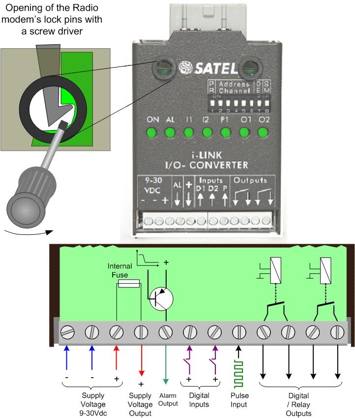
6 1 GENERAL 1.1 SATEL i-link Pulse Counter and I/O -converter The SATEL i-link is a Point-to-Point or Point-to-Multipoint transparent I/O-converter with a pulse counter input. The device works together with SATELLINE-1870E radio modems. In Point-to Point transmission the digital status information can be sent through the radio modem to output in the other end. In Point-to-Multipoint mode it is also possible to read information from pulse transponders. Point-to-Multipoint transmission is possible adopting software suitable for the SATEL i-link. Screw connectors from left to right 1 = minus i-link ground 3 = 9-30 VDC / - + Supply Voltage 4 = + OUT + out for other devices 5 = AL OUT Alarm output 6, 7 = I1, I2 Digital inputs 8 = 10 khz Pulse Input 9-12 = O1, O2 Digital outputs from internal relay contacts Indicators ON Power ON/OFF ALARM Failure in transmission/device I1, I2 Digital inputs O1, O2 Digital outputs P1 Pulse counter input DIP-Switches 8 pcs 1 PRTCL, Protocol 0=P-to-P, 1=Point-to-Multipoint 2, 3, 4, 5 / P-to-P ADDRESS. Max 15. 2, 3, 4, 5 / P-to-MP CHANNEL. 10 channels. 6 Transmission cycle 0= once/ second (by European standard) 1= 3 times/second 7 DE Alarm Delay. 1=ON. 0= OFF 8 SM Safe Mode. 1=ON. 0= OFF 6
7 2 SPECIFICATIONS FEATURE min-max typical note Supply Voltage Vdc Supply Voltage to i-link regulated by the radio modem (5.3 Vdc) Power consumption VA 40 12Vdc Serial Interface RS-232 ± 15 Vdc ± 6 Vdc active RS-232 Response time < 250 ms < bps Operational temperature o C Transfer rate 9600 bps PULSE COUNTER Inputs, 1 pc max. 10 khz Minimum pulse width 5 µs DIGITAL SIGNALS Inputs, 2 pcs 0 35 Vdc 0 30 Vdc resistive 4-5 kω, Outputs, 2 pcs 0 30 V DC/AC/1 A relay contacts (normal= open) INDICATORS Indicators Power ON/OFF, Digital IN/OUT, Alarm, Pulse IN. OTHER OUTPUTS Alarm Output Vdc / 30 ma Alarm= + supply voltage drive current 30 ma. GENERAL Housing Connectors Size L x W x H Weight Mounting IP Modem compatibility Metal plate, painted 16 pins for radio modem 12 pins for other connections 123 x 85 x 30 mm 80 g Wall plate IP-20 SATELLINE-1870E 7
8 3 FUNCTIONS Screw connector functions 3.1 Supply Voltage, 9 30 Vdc o The minus contacts are in parallel. One is for the i-link and another can be used for external devices and connections. Plus (+) is for supply voltage. 3.2 Alarm output, AL OUT o The AL OUT is activated, when three transmission fails has occurred one after another. When activated the AL OUT goes to +VDC. Driving current is max. 30 ma OUT o + OUT is internally connected to + VDC through an automatic fuse. The supply voltage for other devices. o Connections can be taken from the +OUT. 3.4 Digital Inputs, I1, I2, and Outputs O1, O2 o Inputs, o 2 pcs. Activated with + VDC. A transmission is made always when there is a change in the input (P-to-P). Minimum Voltage for 1 -state triggering is 7 Vdc. o Outputs, o 2 pcs. Open relay contacts. Max. rating 9 30 VDC / AC / 1 A load. 3.5 Pulse Input Can be used only in Point-to-Multipoint mode. o For fast pulses. Maximum frequency is 10 khz. 3.6 Indicators o ON o Power ON/ OFF. Illuminated when +VCD is connected. Blinking, if the device is not working. o O1 O2, PO PO1 o Showing the status of the input and output. Illuminated when the consequently pin is activated. o ALARM o Illuminated, if a fail in transmission has occurred. If the i-link has not received confirmation to the sent message, it will repeat the transmission. Three fails in turn switches the AL OUT and the alarm LED ON. 8
9 o I1 I2, PI1 PI2 o Showing the status of the Input. Illuminated when the consequently pin is activated. 3.7 DIP-Swithces DIP -switches, 8 pcs 1 MP, Protocol-switch 1= M, for Point-to-Multipoint (Master-Slave) -operation 0= P, for Point-to-Point -operation Point-to-Multipoint operation mode 2, 3, 4, 5, ADDRESS Used in Point-to-Multipoint -operation to set channel for the sub-station. Maximum number of addresses is Address selection table DIP DIP = reserved for the Main Station = address = address = address = address = address = address = address = address = address = address = address = address = address = address = address 15 Point-to-Point operation mode 2, 3, 4, 5 CHANNEL Used in Point-to-Point-operation to select / change the operational channel. When the power is turned ON, the i-link reads the channel information from the DIP - switches. Default mode setting is , 1=up / 0=down. The channel can be changed by turning first the power OFF and then by setting the DIP - switches (channel selector) to selected channel position for example
10 3.7.3 Channel selection table DIP =disable (channel selection is not in use) =ch =ch =ch =ch =ch =ch =ch =ch =ch =ch10 NOTE1! Check, that both i-links are set to the same channel before turning the power ON. New channel is activated when the power is turned ON. NOTE2! The i-link unit will not operate with these settings: 1011, 1100, 1101, 1110 or The power ON indicator starts to blink in case any of these settings has been chosen. ADDRESS/ CHANNEL/DE-SM 7 DE Delayed alarm o Immediate / Delayed Alarm In case of a failure in the transmission, the alarm output response can be selected from immediate alarm to 10 seconds delayed alarm. 8 SM Safe Mode o Unchanged output state / Safe Mode state In case a failure in transmission, the outputs can be set to remain their status (unchanged) or change to Safe Mode which will switch all outputs to OFF-position. Safe Mode timing follows the setting of the switch 7 DE, so it can be immediate or delayed by 10 seconds. Selection table of the Dip switches 7 and 8 7DE 8SM 0 0 = Immediate Alarm / No Safe Mode 0 1 = Immediate Alarm / Immediate Safe Mode 1 0 = Alarm delayed by 10 seconds / No Safe Mode 1 1 = Alarm delayed by 10 seconds / Safe Mode delayed by 10 seconds 6 Selecting of the transmission standard According to the European standard for free channel operation, the ratio of the transmission cycle must not be more than 10/90. This is active when the DIP-switch number 6 is 0. In position 1 the cycle is faster. Selection table of the DIP-switch number 6 0= one transmission cycle per second 1= 3 transmission cycles per second. 10

 will be sent to the other unit always, when there is a change at the input. 4.1.")

11 4 OPERATION The Operation mode is selected using the PRTCL-switch. The operations are Point-to-Point or Point-to-Multipoint. In Point-to-Point operation mode the system consists of one pair of units. The inputs of the unit are transmitted as outputs of the other unit. In Multipoint mode the main-station controls the sub-stations. 4.1 Point- to-point Point-to-Point operation is between two units. The inputs of the unit are transmitted as outputs of the other unit Updating Digital messages Digital information (relay, switch etc.) will be sent to the other unit always, when there is a change at the input Start of the Point-to-Point operation o Connect radio modem to i-link directly to its connector and check that it is locked. o The MP-switch must be 0, in the P-to-P-position. o Before connecting the device to a power supply, connect first all inputs and outputs that are to be used. o When both units have these basic settings the supply voltage can be connected. o Check that the channel switches 2, 3, 4, 5 = 0000, unless they are purposely selected for a specific channel for example 2, 3, 4, 5= 0101= channel 5 (see chapter 3.7 /channel selection table). 4.2 Point-to-Multipoint In this mode the program at the main station controls the units of the sub stations. The main station can drive one or more sub stations (maximum 15 pcs / system) Start of the Multipoint operation o Connect one SATELLINE radio modem to the COM-Port of the PC. o Connect the i-link slave(s) to the radio modems. o The MP - switch must be 1, in the P-to-MP-position. o Before connecting the device to a power supply, connect first all inputs and outputs that are to be used. o Set individual address to all slaves. (As this is a master slave operation, the slaves have to be addressed). All slaves must have different address (see chapter 3.7 /address selection table. o Start using the system by the master by opening the controlling program for example SATELLINK PC Pro etc. o With the program it is possible to turn ON / OFF the outputs and monitor the inputs. 11
12 Please contact local SATEL distributor or visit SATEL s web site in order to get information of the multipoint commands. 12
13 5 FACTORY SETTINGS The i-link I/O -converter is shipped with the following default settings (unless specifically ordered with settings other than those listed below): FIXED SETTINGS DEFINED AT THE TIME OF ORDER PM, protocol switch, P-to-P or Multipoint 0 = Point-to-Point ADDRESS/CHANNEL 0000 = No address Transmission cycle 0 = 1/sec (European std.) DE, Alarm delay 0 = No Delay SM, Safe mode 0 = No Safe Mode 13

14 6 CONNECTION EXAMPLES Point-to-Multipoint Point-to-Point 14

15 7 ACCESSORIES SATELLINK PC and SATELLINK PC Pro Programs that make it possible to operate a Multipoint system with a PC. Layout of the SATELLINK PC Pro Multipoint-program 15

16 SATEL Oy P.O. Box 142, FI SALO, FINLAND Street: Meriniitynkatu 17, FI SALO, FINLAND Tel , info@satel.com 16
M2M i-link POINT-TO-MULTIPOINT INSTALLATION INSTRUCTIONS
 M2M i-link POINT-TO-MULTIPOINT INSTALLATION INSTRUCTIONS 1 TABLE OF CONTENTS 1 TABLE OF CONTENTS... 2 2 GENERAL... 3 3 INSTALLATION... 4 3.1 SUB-STATIONS... 4 3.2 MAIN STATION (PC)... 4 4 CONNECTING THE
SLR6. Radio Modem Transceiver. User Guide
 SLR6 Radio Modem Transceiver User Guide 1 TABLE OF CONTENTS TABLE OF CONTENTS... 2 1 IMPORTANT NOTICE... 3 2 RESTRICTIONS ON USE... 4 3 PRODUCT CONFORMITY... 6 4 WARRANTY AND SAFETY INSTRUCTIONS... 7 5
SATEL Compact-4BT. Mobile radio modem transceiver
 SATEL Compact-4BT Mobile radio modem transceiver USER GUIDE 1 TABLE OF CONTENTS TABLE OF CONTENTS... 2 1 IMPORTANT NOTICE... 4 2 RESTRICTIONS ON USE... 5 3 PRODUCT CONFORMITY... 7 4 WARRANTY AND SAFETY
OEM PRODUCTS WIRELESS WORLD LOCAL SOLUTION
 OEM PRODUCTS 2008 www.satel.com 2 M3 The M3 is a small and light-weight radio modem designed for integration into the user s terminal equipment. The modem and transceiver are enclosed in a steel or aluminium
High-set undervoltage stage with definitetime. or inverse definite minimum time (IDMT) characteristic. Low-set undervoltage stage with definitetime
 characteristic. Low-set undervoltage stage with definitetime") Issued: 5.06.999 Status: 5.06.999 Version: B/09..00 Data subject to change without notice Features Overvoltage and undervoltage protection Single- or three-phase operation High-set overvoltage stage with
Issued: 5.06.999 Status: 5.06.999 Version: B/09..00 Data subject to change without notice Features Overvoltage and undervoltage protection Single- or three-phase operation High-set overvoltage stage with
CFO900 Series. User Manual. Audio/Data/Current Loop Mux/Demux CSX111, CSX123 & CSX222. CFO CSX series user manual, , rev003
 CFO900 Series User Manual Audio/Data/Current Loop Mux/Demux CSX, CSX23 & CSX222 CFO CSX series user manual, 59300048, rev003 Contents The CSX Series Multiplexer Introduction... Introduction... Frame installation...2
MD-45 AC MD-45 LV/HV INSTALLATION MANUAL
 MD-45 AC MD-45 LV/HV INSTALLATI MANUAL 6157-2213 Westermo Teleindustri A 2003 REV.A Galvanic Isolation Transient Protection alanced Transmission CE Approved Converter RS-232 RS-422/485 www.westermo.us
USER MANUAL MODEL Parallel to Serial/ Serial to Parallel Interface Converter
 USER MANUAL MODEL 2029 Parallel to Serial/ Serial to Parallel Interface Converter C E R T I F I E D An ISO-9001 Certified Company Part #07M2029-B, Rev. C Doc. #102011UB Revised 6/16/09 SALES OFFICE (301)
PULSE INPUT MODULE PI232/PI272 USER S MANUAL
 UM-TS02 -E021 PROGRAMMABLE CONTROLLER PROSEC T2-series PULSE INPUT MODULE PI232/PI272 USER S MANUAL TOSHIBA CORPORATION Important Information Misuse of this equipment can result in property damage or human
Radio Control Installation and Operating Instructions System 4
 Radio Control Installation and Operating Instructions System 4 P.O. Box 403, One Cedar Parkway, Jackson, WI 53037 Phone: 800-628-1909 Fax: 262-677-2058 Revision: April 19, 2012 Contents Introduction 3
Owner s Manual S10 SERIES ELECTRONIC STEP CONTROLLER WITH VERNIER CONTROL
 Owner s Manual S10 SERIES ELECTRONIC STEP CONTROLLER WITH VERNIER CONTROL This manual covers installation, setup, operation and troubleshooting. Read carefully before attempting to install, operate or
SATELLINE -3AS NMS Epic SATELLINE -3AS NMS 869 SATELLINE -3AS VHF
 SATELLINE -3AS NMS SATELLINE -3AS NMS Epic SATELLINE -3AS NMS 869 SATELLINE -3AS VHF Radio Data Modems USER GUIDE Version 1.0 IMPORTANT NOTICE All rights to this manual are owned solely by SATEL OY (referred
IMPORTANT NOTICE. SATELLINE-3AS NMS / Epic NMS / VHF User Guide, Version 6.0
 IMPORTANT NOTICE All rights to this manual are owned solely by SATEL OY (referred to in this user guide as SATEL). All rights reserved. The copying of this manual (without the written permission from the
GPRS-T2. GPRS/SMS Reporting Module. SATEL sp. z o.o. ul. Schuberta Gdańsk POLAND tel
 GPRS/SMS Reporting Module GPRS-T2 Program version 1.0 gprs-t2_en 11/08 SATEL sp. z o.o. ul. Schuberta 79 80-172 Gdańsk POLAND tel. + 48 58 320 94 00 info@satel.pl www.satel.pl WARNINGS The module should
Fiber Optic Expansion Interface
 User Manual for the HE697FBX100 & HE697FBX105 Fiber Optic Expansion Interface Fourth Edition 20 November 1998 MAN0215-04 PREFACE 20 NOV 1998 PAGE 2 PREFACE This manual explains how to use the Fiber Optic
Installation Guide Multi Position Servo Controller E1100-MP and E1100-MP-HC
 Installation Guide Multi Position Servo Controller E00-MP and E00-MP-HC Content IMPORTANT NOTES FOR E00 SERIES CONTROLLERS 2 SYSTEM OVERVIEW 3 E00-MP SERIES FUNCTION AND WIRING 4 E00-MP-HC SERIES FUNCTION
maxon document number:
 maxon document number: 791272-04 1 Table of contents... 2 2 Table of figures... 3 3 Introduction... 4 4 How to use this guide... 4 5 Safety Instructions... 5 6 Performance Data... 6 6.1 Motor data... 6
HURRICANE Radio Modem. FULL DUPLEX Radio MODEM
 FULL DUPLEX Radio MODEM Direct Cable Replacement Range 2KM RS232 / RS485 / USB Host Data Rates up to 38,400 Baud RF Data Rates to 115200Kbps Waterproof IP68 Enclosure 8 User Selectable Channels CE Compliant
INSTRUCTION MANUAL. IBRit - rf1 - usb PC - Station for wireless Data transmission. M e s s t e c h n i k. Messtechnik GmbH & Co.
 M e s s t e c h n i k INSTRUCTION MANUAL PC - Station for wireless Data transmission Document No. : D1F604 001 Version : April 2006 Copyright : IBR Messtechnik GmbH & Co. KG Contents 1. Introduction 1.1
Data Acquisition Modules/ Distributed IO Modules
 User Manual Data Acquisition Modules/ Distributed IO Modules Future Design Controls, Inc. 7524 West 98 th Place / P.O. Box 1196 Bridgeview, IL 60455 888.751.5444 - Office: 888.307.8014 - Fax 866.342.5332
MDW-45 Converter RS RS-422/485
 www.westermo.com MDW-45 Converter RS-232 - RS-422/485 2 6617-2203 General information Legal information The contents of this document are provided as is. Except as required by applicable law, no warranties
INSTALLATION MANUAL FOR RADIO CONTROL SESAM 6099 TRANSMITTER
 1 (12) MANUAL FOR RADIO CONTROL SESAM 6099 TRANSMITTER 2 (12) Revision History Document ID Version Date Reason A0 2008-01-14 First edition Minor reformatting 3 (12) Table of Contents Revision History...2
Application Note: CBLIO-ISO1-xM Cables for the Class 5 D-Style SmartMotor, Revised: 11/9/2016.
 Copyright Notice 2016, Moog Inc., Animatics. Application Note: CBLIO-ISO1-xM Cables for the Class 5 D-Style SmartMotor,. This document, as well as the software described in it, is furnished under license
Instruction also available on
 TERA Radon Program EN TCR3 Central Unit Technical Specifications & Operation Manual v.2 2016 Table of Contents 1 Introduction...2 2 Description and Utilization...2 3 Scope of Delivery...4 4 Product Specification...5
F2A3X Frequency to Analog Converter Module
 the professional s choice F2A3X Frequency to Analog Converter Module Instruction Manual MONARCH INSTRUMENT 15 Columbia Drive Amherst, NH 03031 USA Phone: (603) 883-3390 Fax: (603) 886-3300 E-mail: support@monarchinstrument.com
Instruction. Actuator ICAD 600 / ICAD 900 / ICAD 1200 ICAD 600 ICAD 900 ICAD 1200 ICAD 600 ICAD 900. ICAD 1200 Fig. 2. Fig. 4
 Instruction 027R9796 027R9796 Actuator ICAD 600 / ICAD 900 / ICAD 1200 ICAD 600 ICAD 900 ICAD 1200 ICAD 600 ICAD 900 ICAD 1200 Fig. 1 Fig. 2 Note: When mounting the ICAD make sure to push ICAD down to
ADA-1028L. User manual ADA-1028L. RS232 to Current Loop 2-wire CLO Converter. 1 io_ada-1028l_v.1.10_en. Copyright CEL-MAR sp.j.
 User manual ADA-1028L to Current Loop 2-wire Converter Copyright 2001-2017 CEL-MAR sp.j. 1 io_ada-1028l_v.1.10_en Contents 1. GENERAL INFORMATION... 3 1.1. WARRANTED INFORMATION... 3 1.2. GENERAL CONDITIONS
VFSC9 ELECTRONIC SPEED CONTROLLER. Mounting and operating instructions
 ELECTRONIC SPEED CONTROLLER Mounting and operating instructions Table of contents SAFETY AND PRECAUTIONS 3 PRODUCT DESCRIPTION 4 ARTICLE CODES 4 INTENDED AREA OF USE 4 TECHNICAL DATA 4 STANDARDS 5 WIRING
Frequently Asked Questions ConnexRF Products
 ConnexRF Products Version 1.1 PKLR2400S-200A PKLR2400S-10 LX2400S-3A LX2400S-10 13256 W. 98 TH STREET LENEXA, KS 66215 (800) 492-2320 www.aerocomm.com wireless@aerocomm.com DOCUMENT INFORMATION Copyright
CCE Image may differ from the actual product By Martin Labbé, eng., Jasmin Goupil & Louis Perreault
 CCE-32 1.09 Image may differ from the actual product By Martin Labbé, eng., Jasmin Goupil & Louis Perreault Index 1. General description... 5 2. Applications... 5 3. Installation... 5 4. Connections...
f/i Pulse converter 6420
 Nokeval No 050302 f/i Pulse converter 1 Contents Description... 3 Pulse converter... 3 Technical specification... 4 Dimensions... 4 Terminal connections... 5 MekuWin software... 6 Preparing... 6 Configuration...
Valve amplifier for proportional directional valves and proportional pressure valves. Type VT-VSPA2-1. Features. Contents
 Valve amplifier for proportional directional valves and proportional pressure valves Type VT-VSPA2-1 RE 30110 Edition: 2013-04 Replaces: 05.12 Component series 2X Analog, euro-card format Suitable for
ies-2309 Integrated Easy Servo
 Datasheet of the integrated easy servo motor ies-09 ies-09 Integrated Easy Servo Motor + Drive + Encoder, 0-0VDC, NEMA, 0.9Nm Features Easy servo control technology to combine advantages of open-loop stepper
INSTALLATIONSANVISNING INSTALLATION MANUAL INSTALLATIONS ANLEITUNG MANUEL D INSTALLATION MD-45 AC MD-45 LV/HV
 MD-45 AC MD-45 LV/HV INSTALLATISANVISNING INSTALLATI MANUAL INSTALLATIS ANLEITUNG MANUEL D INSTALLATI 6157-2003 Westermo Teleindustri A 2003 REV.A Galvanic Isolation Transient Protection alanced Transmission
Z-10-D-IN. RS485 Modbus Module 10 Digital Inputs
 S SENECA Z-PC Line EN Installation Manual Contents: - General specifications - Technical specifications - Installation rules - Electrical connections - Modbus connection rules - DIP-switches settings -
FAST SAMPLING CONVERTER
 FAST SAMPLING CONVERTER ML4-F1 HIGH SAMPLING RATE CONVERTER (UP TO 400 SAMPLES/SECOND) Warranty conditions are available on this website: www.isomag.eu only in English version INDEX TECHNICAL DATA... 3
PREMIER INSTALLATION AND OPERATING INSTRUCTIONS
 PREMIER INSTALLATION AND OPERATING INSTRUCTIONS Copyright 2002-2006, PRI Ltd. 9600-3003-2 Issue C Information contained within this document is subject to change without notice and does not represent a
1995 Metric CSJ SPECIAL SPECIFICATION ITEM Drop/Insert Multiplexor/Demultiplexor
 1995 Metric CSJ 3256-02-049 1.0 Description SPECIAL SPECIFICATION ITEM 6093 Drop/Insert Multiplexor/Demultiplexor This Item shall govern for the furnishing and installation of intelligent drop/insert multiplexor/demultiplexors
Logosol AC/DC Intelligent Servo Drive for Coordinated Control LS-174WP
 Features Motors supported: - Panasonic A and S series - Brushless 60/120 commutated - Brush-commutated (DC) motors Up to 20A peak, 12A continuous output current 12 to 90VDC power supply Separate motor
MODEL: DAST-20. Telemetering System
 MODEL: DAST-0 Telemetering System TELEMETERING SYSTEM Functions & Features Small-scale telemetering system Lightning arrester protecting telephone circuit standard Approved of Technical Requirements Compliance
CD770 DIGITAL MULTIMETER INSTRUCTION MANUAL
 CD770 DIGITAL MULTIMETER INSTRUCTION MANUAL Table of Contents 1 SAFETY PRECAUTIONS Before use, read the following safety precautions.- 1-1 Explanation of Warning Symbols 001 1-2 Warning Messages for Safe
Precipitation Monitor ,
 THE WORLD OF WEATHER DATA - THE WORLD OF WEATHER DATA - THE WORLD OF WEATHER DATA Instruction for use 021197/11/09 Precipitation Monitor 5.4103.10.000, 5.4103.10.700 ADOLF THIES GmbH & Co. KG Hauptstraße
ADA User manual ADA RS-232 to RS-485 / RS-422 Converter
 User manual RS- to RS- / RS- Converter Copyright 001-01 CEL-MAR sp.j. 1 io_ada-100_v._en Contents 1. GENERAL INFORMATION... 1.1. WARRANTED INFORMATION... 1.. GENERAL CONDITIONS FOR SAFE USE... 1.. CE LABEL...
02/11/2015
 Modem communication plug and play solutions GSM Part number 88970119 For remote control of your application Automatic notification of alarms via SMS (GSM Modem) / email or on a PC with M3 ALARM software.
02/11/2015
 Modem communication plug and play solutions GSM Part number 88970119 For remote control of your application Automatic notification of alarms via SMS (GSM Modem) / email or on a PC with M3 ALARM software.
MBC Bipolar Microstep Driver. User s Guide E. Landon Drive Anaheim, CA
 MBC10641 Bipolar Microstep Driver User s Guide A N A H E I M A U T O M A T I O N 4985 E. Landon Drive Anaheim, CA 92807 e-mail: info@anaheimautomation.com (714) 992-6990 fax: (714) 992-0471 website: www.anaheimautomation.com
RSMFX-2R MULTIFUNCTIONAL
 Mounting and operating instructions Table of contents SAFETY AND PRECAUTIONS 3 PRODUCT DESCRIPTION 4 ARTICLE CODES 4 INTENDED AREA OF USE 4 TECHNICAL DATA 4 STANDARDS 4 OPERATIONAL DIAGRAMS 5 WIRING AND
RA / /6. Replaces: Table of contents RA /06.98
 Electronic amplifier for the control of proportional directional ales with electrical position feedback Models VT 5024 and VT 5025, Series 1X RA 29 958/06.98 Replaces: 11.97 The amplifiers VT 5024 and
REK 510 Current injection device for earth-fault protection of a synchronous machine rotor. User s Manual
 REK 50 protection of a synchronous machine User s Manual REK 50 X 0 9 8 7 6 5 4 0 V 00 V 0 V 5 6 7 Ordering No: REK 50-AA Uau = 00/0 Vac Un = 48 V Serial No: fn = 50/60 Hz Uec = ma 600 Vdc MRS 75587-MUM
Jacket heater, etc Mounting bracket for Pipe wrapping. (Optional) Temperature sensor. Output (To heater) (Optional)
 Temperature sensor. Output (To heater) (Optional)") Temperature Controller with Built-in SSR SB SB General Description SB is a channel temperature controller with Built-in SSR (Solid state relay) designed for flexible heating solutions such as heat trace
Temperature Controller with Built-in SSR SB SB General Description SB is a channel temperature controller with Built-in SSR (Solid state relay) designed for flexible heating solutions such as heat trace
Astra-R Kit Wireless Alarm System Operation Manual
 Astra-R Kit Wireless Alarm System Operation Manual This operation manual describes principles of functioning, proper use, maintenance and service for the wireless alarm system Astra- R Kit (Figure 1).
Service Instructions. The Conductor Controls. Conductor DC15-A, Enclosed Unit CH15-A, Open Chasis Unit
 Service Instructions The Conductor Controls Conductor DC15-A, Enclosed Unit CH15-A, Open Chasis Unit Table of Contents General Section Page Safety Instructions.. 4 Introduction 5 Inspection and Long-Term
F290X / F293X FOM II Series Fiber Optic Isolator Technical Manual
 F290X / F293X FOM II Series Fiber Optic Isolator Technical Manual Revision G Copyright 2017 VERSITRON, Inc. 83 Albe Drive / Suite C Newark, DE 19702 www.versitron.com E031130243 PROPRIETARY DATA All data
SL300 Snow Depth Sensor USL300 SNOW DEPTH SENSOR. Revision User Manual
 USL300 SNOW DEPTH SENSOR Revision 1.1.2 User Manual 1 Table of Contents 1. Introduction... 3 2. Operation... 3 2.1. Electrostatic Transducer... 4 2.2. SL300 Analog Board... 4 2.3. SL300 Digital Circuit
Industrial Modbus I/O Modules
 Industrial Modbus I/O Modules Modbus I/O Modules Introduction & Features Digital Input / Output Modules Analog Input / Output Modules Modbus I/O Modules The Best Choice For Your SCADA Applications Introduction
High power radio transmission module MR03 type
 High power radio transmission module MR03 type User s manual CONTENTS 1. APPLICATION...3 2. MR03 MODULE SET...4 3. INSTALLATION...4 3.1 Module assembly...4 3.2 Connection diagrams...5 3.3 Connection way
NSPL-500. AIS/VHF antenna splitter. User Manual ENGLISH.
 NSPL-500 AIS/VHF antenna splitter User Manual ENGLISH www.bandg.com www.simrad-yachting.com www.lowrance.com Preface As Navico is continuously improving this product, we retain the right to make changes
Modular Radio Telemetry System
 Simple to Use Remote Control 8 Channels per Transmitter 16 Channels per Receiver Upto 48 Transmitters per system Auto Transmit Mode Secure RF Protocol Automatic Watchdog Transmission Range: Upto 200 metres
Mounting instruction and operating manual. Access Point (UK) HmIP-HAP-UK
 HmIP-HAP-UK") Mounting instruction and operating manual Access Point (UK) HmIP-HAP-UK Package contents Quantity Description 1 Homematic IP Access Point (UK) 1 Plug-in mains adapter 1 Network cable 2 Screws 2 Plugs 1
Mounting instruction and operating manual Access Point (UK) HmIP-HAP-UK Package contents Quantity Description 1 Homematic IP Access Point (UK) 1 Plug-in mains adapter 1 Network cable 2 Screws 2 Plugs 1
RT-5005/5006/5007/5008
 Replaces: 09.12 Electro-hydraulic Control Digital Proportional Amplifier Type: RT-5005/5006/5007/5008 Series: 3X Table of contents Contents Page Features 1 Ordering code 2 Functional description 2 Block
Integrated Easy Servo
 ies 1706 Integrated Easy Servo Motor + Drive + Encoder, 18 32VDC, NEMA17, 0.6Nm Features Easy servo control technology to combine advantages of open loop stepper systems and brushless servo systems Closed
ES86 Series Closed-loop Stepper Drive + Motor System (Drive+ Motor/Encoder)
") ES86 Series Closed-loop Stepper Drive + Motor System (Drive+ Motor/Encoder) Traditional stepper motor drive systems operate open loop providing position control without feedback. However, because of this,
ES86 Series Closed-loop Stepper Drive + Motor System (Drive+ Motor/Encoder) Traditional stepper motor drive systems operate open loop providing position control without feedback. However, because of this,
Communicative heating controller
 UC100 Communicative heating controller Summary UC100 is a communicative room heating controller with one PWM output for control of a radiator or electrical heater. It can work autonomously, or in connection
TECHNICAL DATASHEET #TDAX INPUTS, 5 OUTPUTS VALVE CONTROLLER
 TECHNICAL DATASHEET #TDAX020510 6 INPUTS, 5 OUTPUTS VALVE CONTROLLER Up to 6 Digital, Analog or PWM Command Inputs 5 Independent Proportional or On/Off Outputs 1 +5V, 100 ma Reference Voltage CAN (SAE
DP2500 DP0100 DP0250 Differential Pressure Transmitter
 PB_DP_03 2011 DP2500 DP0100 DP0250 Differential Pressure Transmitter The DP Low Differential Pressure Transmitter series is an accurate and cost competitive solution for measuring low pressures of air
P/N: AX TECHNICAL DATASHEET #TDAX Single Input, Dual Output Valve Controller 1 Universal Input, +5V reference CAN (SAE J1939)
") TECHNICAL DATASHEET #TDAX022000 Single Input, Dual Output Valve Controller 1 Universal Input, +5V reference (SAE J1939) Features: 1 universal signal input 2 proportional or on/off outputs up to 3 A User
TECHNICAL DATASHEET #TDAX022000 Single Input, Dual Output Valve Controller 1 Universal Input, +5V reference (SAE J1939) Features: 1 universal signal input 2 proportional or on/off outputs up to 3 A User
PRetrans Table of contents
 HART TRANSPARENT REPEATER PRetrans 5106 Table of contents Warnings 16 Safety instructions 17 EC Declaration of Conformity 19 How to demount SYSTEM 5000 20 Application 21 Technical characteristics 21 Mounting
Electromotoric actuators for valves
 ACVATIX TM Electromotoric actuators for valves SAT.. Electromotoric actuators with 5.5 mm stroke and 300 N positioning force SAT31.. Operating voltage AC 230 V, 3-position control signal Operating voltage
LBI-38808B. Maintenance Manual EDACS UTILITY PROGRAMMING
 LBI-38808B Maintenance Manual EDACS UTILITY PROGRAMMING NOTICE! Repairs to this equipment should be made only by an authorized service technician or facility designated by the supplier. Any repairs, alterations
IQ SENSOR NET MIQ/MC(-A)-RS
-RS") ESC OK! OK Operating Manual IQ SENSOR NET MIQ/MC(-A)-RS Power C M S Modem Radio Remote connection to the IQ SENSOR NET System 2020 XT via - fixed line telephone network - mobile network - radio link ba64121e03
ESC OK! OK Operating Manual IQ SENSOR NET MIQ/MC(-A)-RS Power C M S Modem Radio Remote connection to the IQ SENSOR NET System 2020 XT via - fixed line telephone network - mobile network - radio link ba64121e03
LBI Installation & Operation
 Installation & Operation EDACS Power Monitor Unit ericssonz CONTENTS TABLE OF CONTENTS Page INTRODUCTION... 6 DESCRIPTION... 6 APPLICATION NOTES... 7 VAX SITE CONTROLLER COMPUTER... 7 APPLICATION SOFTWARE
PM-311x Quick Start Ver PM-311x introduction 1.1. Caution & Warning 1.2. Product Warranty & Customer Support
 PM-311x Quick Start Ver. 1.1 1. PM-311x introduction ICP DAS brings the most powerful, cost-effective, advanced Smart Power Meters PM-3000 series that gives you access to real-time electric usage for single-phase
z475 Remote DC Power Supply Preliminary
 TECHNICAL SPECIFICATIONS z475 Remote DC Power Supply Preliminary 2018 LitePoint, A Teradyne Company. All rights reserved. Overview The z475 remote DC Power supply can provide a stable VCC voltage for PA/FEM/SW
z48831 / z :1/ 16:1 6 GHz Multiplexer Module
 TECHNICAL SPECIFICATIONS z48831 / z48832 8:1/ 16:1 6 GHz Multiplexer Module 2017 LitePoint, A Teradyne Company. All rights reserved. Port Descriptions Front Panel Label Type Description 1-16 SMA RF1 to
Copyright / Trademarks -This manual and its contents are copyrighted. -You may not copy this manual,in whole or part,without written consent of
 Safety Precautions Observe the following notices to ensure personal safety or to prevent accidents. To ensure that you use this product correctly, read this User s Manual thoroughly before use. Make sure
Model FLSC-C3-XX. DC Powered Microprocessor Controlled Transmitter
 Model FLSC-C3-XX DC Powered Microprocessor Controlled Transmitter CONTENTS. Introduction----------------------------------------------------------------- 2 2. Specifications ---------------------------------------------------------------
Blue Point Engineering
 Blue Point Engineering Instruction I www.bpesolutions.com Pointing the Way to Solutions! Animatronic Wizard - 3 Board (BPE No. WAC-0030) Version 3.0 2009 Controller Page 1 The Wizard 3 Board will record
Applications: oil and gas equipment automation; off-highway machine automation; agricultural equipment
 Features: 6 Universal Signal Inputs are user configurable as: o 0-5V, 0-10V, 4-20mA or 0-20mA o 20Ω to 250 kω Resistive o 1 Hz to 10 khz PWM o Digital o Three of the inputs can be configured as a pulse
General Specifications
 General Specifications GS 77J01Q08-01E Model VJQ8 Pulse to Analog Converter (Multi-function) (Isolated Single-output and Isolated Dual-output Types) General This plug-in type pulse to analog converter
DAA AES/EBU Digital Audio Distribution Amplifier. User Manual. I.R.T. Communications Pty Ltd
 AES/EBU Digital Audio Distribution Amplifier User Manual Revision 02 AES/EBU DIGITAL AUDIO DISTRIBUTION AMPLIFIER Revision History: Revision Date By Change Description Applicable to: 00 15/03/2005 AL Original
ERV-M ELECTRONIC FAN SPEED CONTROLLER. Mounting and operating instructions
 ELECTRONIC FAN SPEED CONTROLLER Mounting and operating instructions Table of contents SAFETY AND PRECAUTIONS 3 PRODUCT DESCRIPTION 4 ARTICLE CODES 4 INTENDED AREA OF USE 4 TECHNICAL DATA 4 STANDARDS 5
1993 Specifications CSJ SPECIAL SPECIFICATION ITEM Drop/Insert Multiplexor/Demultiplexor
 1993 Specifications CSJ 0008-12-071 SPECIAL SPECIFICATION ITEM 6550 Drop/Insert Multiplexor/Demultiplexor 1.0 Description. This Item shall govern for the furnishing and installation of intelligent drop/insert
M110A RF MODEM M110A. User's Manual. Ver 2.0. SEBINE Technology, Inc. M110A_ hwp 1
 RF MODEM M110A User's Manual Ver 2.0 SEBINE Technology, Inc. M110A_20090926.hwp 1 CONTENTS 1. Summary 1.1 Product Introduction 1.2 Specification 2. Operation Mode 2.1 PC MODE 2.2 DEVICE MODE 3. Device
Operations Manual Edition 3.1
 Operations Manual Edition 3.1 MREL GROUP OF COMPANIES LIMITED 1555 Sydenham Road, Kingston, Ontario K7L 4V4 Canada T: +1-613-545-0466 F: +1-613-542-8029 E: blasting@mrel.com www.mrel.com ii Copyright Information
2W UHF MHz Radio Transceiver
 2W UHF410-470 MHz Radio Transceiver Specification Copyright Javad Navigation Systems, Inc. February, 2006 All contents in this document are copyrighted by JNS. All rights reserved. The information contained
Fixed Mount Scanner FUZZYSCAN FAMILY. Quick Start Guide FIXED MOUNT SCANNER
 Fixed Mount Scanner FUZZYSCAN FAMILY Quick Start Guide FIXED MOUNT SCANNER Getting Familiar with Your FuzzyScan Thank you for choosing Cino FuzzyScan Fixed Mount Scanner. Built with FuzzyScan. Imaging
Electromotoric actuators for stroke valves
 s ACVATIX Electromotoric actuators for stroke valves SAS.. Electromotoric actuators with 5.5 mm stroke and 400 N positioning force SAS31.. Operating voltage AC 230 V, 3-position control signal Operating
PDL Base. Radio Modem User's Guide. Revision 0.2 (preliminary) May 1999 Copyright 1999 Pacific Crest Corporation Document M00522
 May 1999 Copyright 1999 Pacific Crest Corporation Document M00522") i PDL Base Radio Modem User's Guide Revision 0.2 (preliminary) May 1999 Copyright 1999 Pacific Crest Corporation Document M00522 Pacific Crest Corporation 990 Richard Avenue, Suite 110 Santa Clara, CA
i PDL Base Radio Modem User's Guide Revision 0.2 (preliminary) May 1999 Copyright 1999 Pacific Crest Corporation Document M00522 Pacific Crest Corporation 990 Richard Avenue, Suite 110 Santa Clara, CA
CU-DIN DIM 6-CH 0 10V KNX
 CU-DIN DIM 6-CH 0 10V KNX EC10430329 MA00651401 Table of contents 1 Description... 3 2 Safety Instructions... 3 3 Product Function... 3 4 Hardware... 4 4.1 Technical data... 4 4.2 Dimming mode... 6 4.2.1
ES86 Series Closed-loop Stepper Drive + Motor System (Drive+ Motor/Encoder)
") ES86 Series Closed-loop Stepper Drive + Motor System (Drive+ Motor/Encoder) Traditional stepper motor drive systems operate open loop providing position control without feedback. However, because of this,
ES86 Series Closed-loop Stepper Drive + Motor System (Drive+ Motor/Encoder) Traditional stepper motor drive systems operate open loop providing position control without feedback. However, because of this,
SilverMax Datasheet. QuickSilver Controls, Inc. NEMA 23 Servomotors.
 SilverMax Datasheet NEMA 23 Servomotors QuickSilver Controls, Inc. www.quicksilvercontrols.com SilverMax Datasheet - NEMA 23 Servomotors 23 Frame Sizes: 23-3, 23-5, 23H-1, 23H-3, 23H-5 / Series: E, E3,
1995 Metric CSJ SPECIAL SPECIFICATION ITEM Add/Drop Multiplexor/Demultiplexor
 1995 Metric CSJ 0113-13-109 SPECIAL SPECIFICATION ITEM 6225 Add/Drop Multiplexor/Demultiplexor 1.0 Description. This Item shall govern for the furnishing and installation of intelligent Add/Drop Multiplexor/Demultiplexor
RIGOL. Quick Guide. DG2000 Series Function/Arbitrary Waveform Generator. Sept RIGOL Technologies, Inc.
 Quick Guide DG2000 Series Function/Arbitrary Waveform Generator Sept. 2010 RIGOL Technologies, Inc. Guaranty and Declaration Copyright 2010 RIGOL Technologies, Inc. All Rights Reserved. Trademark Information
HO118 Binning Interface User Manual * * Version 02. User Manual. Test & Measurement
 HO118 Binning Interface User Manual *5800490502* 5800490502 Test & Measurement User Manual Version 02 Important hints Important hints Warranty and Repair Security This instrument has been designed and
Valve amplifier for proportional directional valves. Type VT-VRPA2. Features. Contents. RE Edition: Replaces: 07.05
 Valve amplifier for proportional directional valves Type VT-VRPA RE 0119 Edition: 01-0 Replaces: 07.05 Component series 1X Analog, Euro-card format Suitable for controlling / proportional directional valves
PalmGauss SC PGSC-5G. Instruction Manual
 PalmGauss SC PGSC-5G Instruction Manual PalmGauss SC PGSC 5G Instruction Manual Thank you very much for purchasing our products. Please, read this instruction manual in order to use our product in safety
AR-DN-RS232. An-10 / Rapid RS232 Interface. Product Guide. Overview. Features
 AR-DN-RS232 An-10 / Rapid RS232 Interface Product Guide Overview The AR-DN-RS232 is a device that is used as a 2 way gateway between third party systems and the CP An-10 or Rapid lighting control systems
Wireless multizone receiver RDE-MZ6
 s 1 428 Wireless multizone receiver RDE-MZ6 for floor heating / zone heating systems Mains-powered RDE-MZ6 multizone wireless receiver (AC 230 V) DIN rail mounting 2-position control with On/Off output
Trillium US Inc. E500 Dual Channel Temperature Monitor User s Manual Rev A / November 2015
 97-00032-000 Trillium US Inc. E500 Dual Channel Temperature Monitor User s Manual Rev A / November 2015 For information about Trillium US Inc., visit the Trillium US Inc. Web site at: http://www.trilliumus.com
SPECIAL SPECIFICATION 1789 Fiber Optic RS-232 Data Modem
 1993 Specifications CSJ 2266-02-095 SPECIAL SPECIFICATION 1789 Fiber Optic RS-232 Data Modem 1. Description. This Item shall govern for the furnishing and installation of Fiber Optic RS- 232 Data Modem