NGM Snubber Capacitors
|
|
|
- Scott Robinson
- 5 years ago
- Views:
Transcription

1 NGM Snubber Capacitors Snubber Capacitors of Metalized Polypropylene Film With Internal Series Connection Features Very High Pulse Strength High Current Highest possible contact reliability RoHS-compatible Typical Applications Snubbering IGBT protection circuits Filtering Rated capacitance range Capacitance Tolerance Dissipation factor at 20 C, 10 khz Rated DC Voltage, UNDC Operating temperature range Climatic testing class Rated AC Voltage Reference standards Insulation resistance RINS or time constant T=(CR)(RINS) at 20 C DC test voltage Category voltage VC (continuous operation with VDC or VAC at f 1 khz Operating voltage Vop for short operating periods (VDC or VAC at f 1 khz) Damp heat test Limit values after damp heat test Technical Data 0.47µF-10µF ±5% 1x10.3 3x V, 850V, 1000V, 1250V, 1600V, 2000V, 2500V Upper category temperature Tmax Lower category temperature Tmin Rated temperature TR +105 C -55 C +85 C 55/105/56 420V, 400V to 450V, 425V to 500V, 450V to 550V. 450V to 600V, 700V, 800V TA TA 100 CR 0.33µF 100GΩ IEC CR>0.33µF s 1.6 x 60s (maximum rise time 1000V/s; cut off current 10mA) TA ( C) DC voltage derating AC voltage derating VC= VR VC=VR (165-TA)/80 TA 85 85<TA 100 VC,RMS= VRMS VC,RMS=VRMS (165-TA)/80 TA ( C) DC voltage (max. hours) AC voltage (max. hours) Vop= 1.25xVC (2000 h) Vop= 1.25xVC (1000 h) 56 days/40 C/93% relative humidity Capacitance change IΔC/CI 2% Dissipation factor change Δ 1x10⁻³ (at 10kHz) Insulation Resistance RINS 50% of minimum or time constant =(CR)(RINS) as delivered values Vop= 1.0 VC,RMS (2000 h) Vop= 1.0 VC,RMS (1000 h) January
2 Reliability: Failure rate Service life tsl Failure criteria: Total failure Failure due to variation of parameters Dielectric Electrodes Construction Encapsulation Terminals Self-Inductance Test voltage between terminals and case 1 fit( 1x10⁻⁹ /h) at 0.5 VR, 40 C h at 1.0 VR, 85 C Short circuit or open circuit Capacitance change IΔC/CI >10% Dissipation factor change Δ 4 upper limit value Insulation Resistance RINS <1500MΩ (CR 0.33µF) or time constant =(CR)(RINS) <500 s (CR>0.33µF) Polypropylene Film Metallized Film Non series and series construction UL94-V0 plastic case and polymeric potted material Tinned coated copper <0.7nH per mm of lead spacing 1.4URAC+2000VDC for 60 s DC Voltage Ratings VDC VAC Construction Dielectric: Polypropylene (PP) film Internal Series Connection Plastic case, epoxy resin sealing (UL 94-V0) Non-series Construction Metallized Polypropylene Metal Spray Layer Series Construction Metallized Polypropylene Triple Construction Metallized Polypropylene Metal Spray Layer Metal Spray Layer January
3 Terminals Strap terminals, tinned copper (max. torque 10 Nm) COMPOSITION OF CATALOG NUMBER MULTIPLIER TOLERANCE J ±5% K ±10% NG J 0700 T8 CAPACITANCE (nf) Voltage Example 0700=700VDC SPECIAL CODE FOR TERMINALS DRAWING L (mm) P 1 (mm) P 2 (mm) DRAWING T ±0.5 23± ±0.5 38±0.5 T ± ± ± ± ±0.5 - T ± ±0.5 - T ±0.5 22± ±0.5 37± ±1 22.7±1 T ±1 32.7± ±1 47.7±1 T ±1 22.7± ±1 37.7± ±1 22.7±1 T ±1 32.7± ±1 47.7±1 T ±1 22.7± ±1 37.7±1 January
4 Working Voltage 700 VDC (420 VAC) Cap W* h* L* dv/dt (V/µs) Ipeak Irms (1) ESR (mω) 1Khz 10 Khz 100Khz Ordering Code NG4701J0700** NG6801J0700** NG1002J0700** NG1502J0700** NG2002J0700** NG2202J0700** NG3002J0700** NG3302J0700** NG4002J0700** NG4702J0700** NG5002J0700** Working Voltage 850 VDC (450 VAC) Cap W* h* L* dv/dt (V/µs) Ipeak Irms (1) ESR (mω) 1Khz 10 Khz 100Khz Ordering Code NG4701J0850** NG6801J0850** NG8201J0850** NG1002J0850** NG1502J0850** NG2002J0850** NG2202J0850** NG3002J0850** NG3302J0850** NG4002J0850** Working Voltage 850 VDC (400 VAC) Cap W* h* L* dv/dt (V/µs) Ipeak Irms (1) ESR (mω) 1Khz 10 Khz 100Khz Ordering Code NG4702J0850** NG5002J0850** NG6002J0850** NG7002J0850** NG8002J0850** NG1003J0850** * See Dimension s diagram (page 15, 16) (1) Maximum RMS current at 100 khz ** Terminal Type January
5 Working Voltage 1000 VDC (500 VAC) Cap W* h* L* dv/dt (V/µs) Ipeak Irms (1) ESR (mω) 1Khz 10 Khz 100Khz Ordering Code NG4701J1000** NG5601J1000** NG6801J1000** NG8201J1000** NG1002J1000** NG1202J1000** NG1502J1000** NG1802J1000** NG2002J1000** NG2202J1000** NG2502J1000** NG2702J1000** NG3302J1000** Working Voltage 1000 VDC (425 VAC) Cap W* h* L* dv/dt (V/µs) Ipeak Irms (1) ESR (mω) 1Khz 10 Khz 100Khz Ordering Code NG3302J1000** NG4002J1000** NG4702J1000** NG5002J1000** NG6002J1000** NG7002J1000** Working Voltage 1250 VDC (550 VAC) Cap W* h* L* dv/dt (V/µs) Ipeak Irms (1) ESR (mω) 1Khz 10 Khz 100Khz Ordering Code NG3301J1250** NG3901J1250** NG4701J1250** NG5601J1250** NG6801J1250** NG8201J1250** NG1002J1250** NG1202J1250** NG1502J1250** NG1802J1250** NG2002J1250** NG2202J1250** * See Dimension s diagram (page 15, 16) (1) Maximum RMS current at 100 khz ** Terminal Type January
6 Working Voltage 1250 VDC (450 VAC) Cap W* h* L* dv/dt (V/µs) Ipeak Irms (1) ESR (mω) 1Khz 10 Khz 100Khz Ordering Code NG2202J1250** NG2502J1250** NG3002J1250** NG3302J1250** NG4002J1250** NG4702J1250** NG5002J1250** Working Voltage 1600 VDC (600 VAC) Cap W* h* L* dv/dt (V/µs) Ipeak Irms (1) ESR (mω) 1Khz 10 Khz 100Khz Ordering Code NG2201J1600** NG2701J1600** NG3301J1600** NG3901J1600** NG4701J1600** NG5601J1600** NG6801J1600** NG8201J1600** NG1002J1600** NG1302J1600** NG1502J1600** NG1802J1600** NG2002J1600** Working Voltage 1600 VDC (450 VAC) Cap W* h* L* dv/dt (V/µs) Ipeak Irms (1) ESR (mω) 1Khz 10 Khz 100Khz Ordering Code NG1502J1600** NG2002J1600** NG2202J1600** NG2502J1600** * See Dimension s diagram (page 15, 16) (1) Maximum RMS current at 100 khz ** Terminal Type January
7 Working Voltage 2000 VDC (700 VAC) Cap W* h* L* dv/dt (V/µs) Ipeak Irms (1) ESR (mω) 1Khz 10 Khz 100Khz Ordering Code NG4701J2000** NG6801J2000** NG1001J2000** NG1201J2000** NG1501J2000** NG2201J2000** NG2701J2000** NG3301J2000** NG3902J2000** NG4702J2000** NG5602J2000** NG6802J2000** NG6802J2000** NG6802J2000** NG1002J2000** NG1502J2000** Working Voltage 2500 VDC (800 VAC) Cap W* h* L* dv/dt (V/µs) Ipeak Irms (1) ESR (mω) 1Khz 10 Khz 100Khz Ordering Code NG4701J2500** NG6801J2500** NG1001J2500** NG1201J2500** NG1501J2500** NG2201J2500** NG2701J2500** NG3301J2500** NG3902J2500** NG4702J2500** NG5602J2500** NG6802J2500** NG6802J2500** NG6802J2500** * See Dimension s diagram (page 15, 16) (1) Maximum RMS current at 100 khz ** Terminal Type January
8 AVAILABLE TERMINALS VDC Cap Ordering Code T1 T2 T3 T4 T5 T6 T7 T NG4701J NG6801J NG1002J NG1502J NG2002J NG2202J NG3002J NG3302J NG4002J NG4702J NG5002J NG4701J NG6801J NG8201J NG1002J NG1502J NG2002J NG2202J NG3002J NG3302J NG4002J0850 January
9 AVAILABLE TERMINALS VDC Cap Ordering Code T1 T2 T3 T4 T5 T6 T7 T NG4701J NG5601J NG6801J NG8201J NG1002J NG1202J NG1502J NG1802J NG2002J NG2202J NG2502J NG2702J NG3302J NG3302J NG4002J NG4702J NG5002J NG6002J NG7002J NG3301J NG3901J NG4701J NG5601J NG6801J NG8201J NG1002J NG1202J NG1502J NG1802J NG2002J NG2202J NG2202J NG2502J NG3002J NG3302J NG4002J NG4702J1250 January
10 NG5002J NG2201J NG2701J NG3301J NG3901J NG4701J NG5601J NG6801J NG8201J NG1002J NG1302J NG1502J NG1802J NG2002J NG1502J NG2002J NG2202J NG2502J NG4701J NG6801J NG1001J NG1201J NG1501J NG2201J NG2701J NG3301J NG3902J NG4702J NG5602J NG6802J NG6802J NG6802J NG1002J NG1502J NG4701J NG6801J NG1001J NG1201J NG1501J NG2201J NG2701J NG3301J2500 January
11 0.39 NG3902J NG4702J NG5602J NG6802J NG6802J NG6802J2500 MOUNTING Normal Use The capacitors are designed for mounting on IGBT or GTO modules. Specific Method of Mounting to Withstand Vibration and Shock In order to withstand vibration and shock tests, the capacitors shall be mechanically fixed by tabs it must be ensured that they are screwed tightly on the best board. When the weight of the capacitor is bigger than 50 g it needs a clamp in the body of capacitors. Storage Temperature T stg= -25 C to +35 C with RH maximum 75% without condensation. Ratings and Characteristics Reference Conditions Unless otherwise specified, all electrical values apply to an ambient temperature of 23 C ± 1 C, an atmospheric pressure of 78 kpa to 106 kpa and a relative humidity of 50% ± 2%. For reference testing, a conditioning period shall be applied over 96h ± 4h by heating the products in a circulating air oven at the rated temperature and a relative humidity not exceeding 20%. January
12 CHARACTERISTICS January

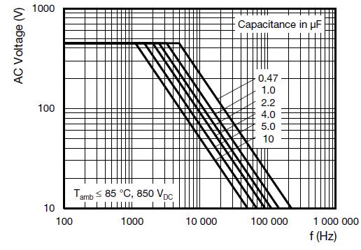
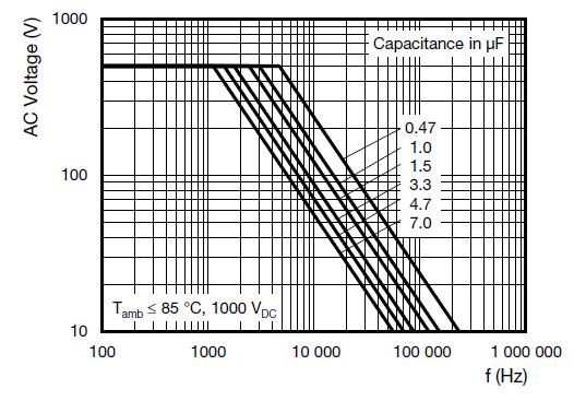
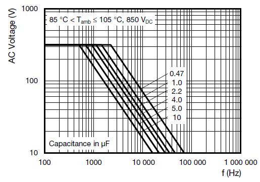
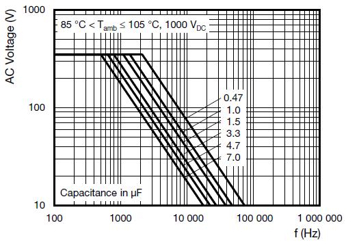
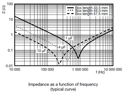
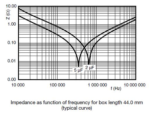
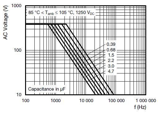
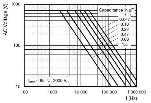
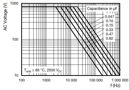
13 MAXIUM RMS VOLTAGE (SINEWAVE) AS A FUNCTION OF FREQUENCY January

14 January
15 CASE DIMENSIONS (mm.) January
16 January
17 MARKING Product Marking and Identification The capacitor is marked by stamp, with following information: 1. - Manufacturer s logo 2. - Single Metallized (e.g. M) 3. - Rated capacitance value (e.g. 5µF) 4. - Tolerance on rated capacitance (e.g. J= ± 5%) 5. - Rated DC voltage (e.g. 700 V) 6. - Year and week of manufacture (e.g. 2315) NGM M 5µF J 700V 2315 POWER DISSIPATION AND MAXIUM COMPONENT TEMPERATURE RISE HEAT CONDUCTIVITY (G) AS A FUNCTION OF ORIGINAL PITCH AND CAPACITOR BODY THICKNESS IN mw/ C W max. (mm) HEAT CONDUCTIVITY (mw/ C) BOX LENGTH 33.5 mm BOX LENGTH 44 mm BOX LENGTH 58 mm The power dissipation must be limited in order not to exceed the maximum allowed component temperature rise as function of the free air ambient temperature. The component temperature rise (ΔT) can be measured or calculated by ΔT =P/G ΔT= Component temperature rise ( C) with maximum of 10 C rise ( C) P= Power dissipation of the component (mw) G= Heat conductivity of the component (mw/ C) January
18 MEASURING THE COMPONENT TEMPERATURE A thermocouple must be attached to the capacitor body as in: The temperature is measured in unloaded (T amb) and maximum loaded condition (T C) The temperature rise is given by ΔT=T C- T amb The avoid radiation or convection, the capacitor should be tested in a wind-free box APPLICATION NOTE AND LIMITING CONDITIONS These capacitors are not suitable for mains applications as across-the-line capacitors without additional protection, as described hereunder. These mains application are strictly regulated in safety standards and therefore electromagnetic interference suppression capacitors conforming the standards must be used. To select the capacitor for a certain application, the following conditions must be checked: 1. The peak voltage (Up) shall not be greater than the rated DC voltage (U RDC) 2. The peak-to-peak voltage (Upp) shall not be greater than the maximum (Upp) to avoid electric arc 3. The maximum component surface temperature rise must be lower than the limits 4. Since in circuits used at voltage over 280 V peak-to-peak the risk for an intrinsically active flammability after the capacitor breakdown (short circuit) increases, it is recommended that the power to the component is limited to 100 times the values mentioned in the table Heat-conductivity 5. When using these capacitors as across-the-line capacitor in the input filter for mains applications or as series connected with an impedance to the mains the applicant must guarantee that the following conditions are fulfilled in any cases spike and surge voltages from the main included VOLTAGE CONDITIONS FOR 5 ABOVE ALLOWED VOLTAGES T amb 85 C 85 C T amb 105 C Maximum continuous RMS voltage U RAC 0.7 x U RAC Maximum temporary RMS overvoltage (<24 h) 1.25 x U RAC x U RAC Maximum peak voltage (V o-p)(<2 s) 1.6 x U RDC 1.1 x U RDC January
19 INSPECTION REQUIREMENTS General Notes Sub-clause numbers of tests and performance requirements are refer to the Sectional Specification, Publication IEC GROUP C INSPECTIONS REQUIREMENTS SUB- CLAUSE NUMBER AND CONDITIONS TEST SUB-GROUP C1A OF SAMPLE OF SUB-GROUP C1 4.1 Dimensions (details) PERFORMANCE REQUIREMENTS Are specified in chapters General Data of this specification Initial measurements Capacitance Tangent of loss angle: For C>1 µf at 1 Khz For C 1 µf at 1 Khz 4.3 Robustness of terminations Tensile: Load 30 N; 10 s No visible damage Final measurements Visual examination No visible damage Legible marking Capacitance ΔC/C 2 % of the value measured initially Tangent of loss angle Increase of tan Compared to values measured initially Insulation resistance SUB-GROUP C1B PART OF SAMPLE OF SUB-GROUP C Initial measurements Capacitance Tangent of loss angle: For C>1 µf at 1 Khz For C 1 µf at 1 Khz 50 % values specified in section Insulation Resistance of this specification 4.6 Rapid change of temperature A= -55 C B=+105 C 5 cylces Duration t=30 min Visual examination No visible damage 4.7 Vibration Mounting: See section Mounting of this specification. Procedure B4: Frequency range: 10 Hz to 55 Hz Amplitude: 0.75 mm or Acceleration: 98 m/s 2 (whichever is less severe) Total duration 6h Final Inspection Visual examination No visible damage January
20 4.9 Shock Mounting: See section Mounting for more information Pulse shape: Half sine Acceleration: 490 m/s 2 Duration of pulse: 11 ms Visual examination Final measurements Capacitance Tangent of loss angle No visible damage ΔC/C 2 % of the value measured initially Increase of tan Compared to values measured initially 4.15 Solvent resistance of the marking Insulation resistance Isopropyl alcohol at room temperature Method:1 Rubbing material: cotton wool Immersion time: 5 min ± 0.5 min 50 % values specified in section Insulation Resistance of this specification No visible damage Legible marking GROUP C INSPECTIONS REQUIREMENTS SUB- CLAUSE NUMBER AND TEST CONDITIONS PERFORMANCE REQUIREMENTS SUB-GROUP C1 COMBINED SAMPLE OF SPECIMENS OF SUB-GROUP C1A AND C1B 4.10 Climatic sequence Dry heat Temperature: +105 C Duration: 16h Cold Temperature: -55 C Duration: 2h Final measurements Voltage proof= URDC for 1 min within 15 min after removal from test chamber Visual examination Capacitance No visible damage Legible marking No breakdown or flash-over No visible damage Legible marking ΔC/C 3 % of the value measured initially Tangent of loss angle Increase of tan Compared to values measured in Insulation resistance 50 % values specified in section Insulation Resistance of this specification January
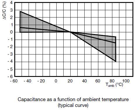
21 GROUP C INSPECTIONS REQUIREMENTS SUB- CLAUSE NUMBER AND CONDITIONS TEST SUB-GROUP C3A Endurance test at 60 Hz Duration: 2000 h alternative voltage 1.25 x URAC at 85 C x URAC at 105 C PERFORMANCE REQUIREMENTS Initial measurements Capacitance Tangent of loss angle: For C>1 µf at 1 Khz For C 1 µf at 1 Khz Final measurements Visual examination No visible damage Legible marking Capacitance ΔC/C 5 % compared to values measured Tangent of loss angle Increase of tan : for C 1 µf for C> 1 µf Compared to values measured in Insulation resistance 50 % values specified in section Insulation Resistance of this specification SUB-GROUP C Temperature characteristics Capacitance For -55 C to 20 C Initial measurements Capacitance at -55 C 0 % ΔC/C 2.75 % or Intermediate measurements Capacitance at 20 C For 20 C to 105 C Capacitance at +105 C -5.5 % ΔC/C 0 % As specified in section Capacitance of this specification 4.13 Charge and discharge cycles Cycle time: 1 c/s Charge: URDC trough a resistor with value 220 x 10 6 R = C R Charge time: 5ms Discharge: Trough a resistor with value R = U C (du/dt) Initial measurements Capacitance Tangent of loss angle: For C>1 µf at 1 Khz For C 1 µf at 1 Khz Final measurements Capacitance ΔC/C 3 % of the value measured in Tangent of loss angle Increase of tan : for C 1 µf for C> 1 µf Compared to values measured in Insulation resistance 50 % values specified in section Insulation Resistance of this specification January
22 Disclaimer ALL PRODUCT, PRODUCT SPECIFICATIONS AND DATA ARE SUBJECTS TO CHANGE WITHOUT NOTICE TO IMPROVE RELIABILITY, FUNCTION OR DESIGN OR OTHERWISE. NG its affiliates, agents, and employees, and all persons acting on its or their behalf (collectively. NG), disclaim any and all liability for any errors, inaccuracies or incompleteness contained in any datasheet or in any other disclosure relating to any product. NG makes no warranty, representation or guarantee regarding the suitability of the products for any particular purpose or the continuing production of any product. To the maximum extent permitted by applicable law, NG disclaims (i) any and all liability arising out of the application or use of any product, (ii) any and all liability, including without limitation special, consequential or incidental damages, and (iii) any and all implied warranties, including warranties of fitness for particular purpose, non-infringement and merchantability. Statements regarding the suitability of products for certain types of applications are based on NG knowledge of typical requirements that are often placed on NG products. Such statements are not binding statements about the suitability of products for a particular application. It is the customer s responsibility to validate that a particular product with the properties described in the product specification is suitable for use in a particular application. Parameters provided in datasheets and/or specification may vary in different applications and performance may vary over time. All operating parameters, including typical parameters, must be validated for each customer application by the customer s technical experts. Products specifications do not expand otherwise modify NG s terms and conditions of purchase, including but not limited to the warranty expressed therein. Except as expressly indicated in writing, NG products are not designed for use in medical, life-saving, or life-sustaining applications or for any other application in which the failure of the Ng product could result in personal injury or death. Customers using or selling Ng products not expressly indicated for use in such applications do so at their own risk. Please contact authorized personnel to obtain written terms and conditions regarding products designed for such applications. No license, express or implied, by estoppel or otherwise, to any intellectual property rights is granted by this document or by any conduct NG. Product names and markings noted herein may be trademarks of their respective owners. January
AC and Pulse Film Foil Capacitors KP Radial Potted Type
 KP 1830 AC and Pulse Film Foil Capacitors L max. W max. Marking FEATURES 5 mm lead pitch, supplied loose in box taped in ammopack or reel 0.5 H max. Material categorization: for definitions of compliance
AC and Pulse Double Metallized Polypropylene Film Capacitors MMKP Radial Potted Type
 Not Recommended for New Design, Use New MMKP383 MMKP 383 Vishay BCcomponents AC and Pulse Double Metallized Polypropylene Film Capacitors MMKP Radial Potted Type 168x12(halfpage) l P h lt w dt 10 l F'
AC and Pulse Metallized Polypropylene Film Capacitors MKP and MKP/MKP Radial Potted Type. LEADS Tinned wire
 AC and Pulse Metallized Polypropylene Film Capacitors MKP and MKP/MKP Radial Potted Type CBB817 Dimensions in mm APPLICATIONS Where steep pulses occur e.g. SMPS (switch mode power supplies). Motor control
Interference Suppression Film Capacitor - Class X2 Axial MKT 253 V AC - Continuous Across the Line
 Interference Suppression Film Capacitor - Class X2 Axial MKT 253 V AC - Continuous Across the Line FEATURES Axial mounting Low building height Material categorization: for definitions of compliance please
Metallized Polypropylene Film Capacitor AC Filtering Radial Type
 Metallized Polypropylene Film Capacitor AC Filtering Radial Type FEATURES High peak current capabilities Long lifetime Material categorization: for definitions of compliance please see www.vishay.com/doc?999
Metallized Polypropylene Film Capacitor AC Filtering Radial Type
 Metallized Polypropylene Film Capacitor AC Filtering Radial Type FEATURES High peak current capabilities Long lifetime Material categorization: for definitions of compliance please see www.vishay.com/doc?9991
Interference Suppression Film Capacitors MKP Radial Potted Type
 Interference Suppression Film Capacitors MKP Radial Potted Type FEATURES 7.5 mm to 27.5 mm lead pitch Supplied loose in box, taped on reel Material categorization: for definitions of compliance please
Metallized Polypropylene Film Capacitor DC-Link Capacitor
 Metallized Polypropylene Film Capacitor DC-Link Capacitor FEATURES High density DC-link capacitor (more C per volume) Very long useful life time: up to 100 000 h at U NDC and 70 C High ripple current capability,
Interference Suppression Film Capacitor - Class X2 Radial MKT 310 V AC - High Stability Grade
 Interference Suppression Film Capacitor - Class X2 Radial MKT 310 V AC - High Stability Grade FEATURES 15 mm to 37.5 mm lead pitch Internal series construction AEC-Q200 qualified for C 470 nf Material
Interference Suppression Film Capacitors MKP Radial Potted Type
 Not Recommended for New esigns - Use MKP338 6 Y2 Interference Suppression Film Capacitors MKP Radial Potted Type FEATURES 10 mm to 15 mm lead pitch Supplied loose in box, taped on reel Material categorization:
MKP X1 Vishay BCcomponents Interference Suppression Film Capacitors MKP Radial Potted Type
 Interference Suppression Film Capacitors 168x12(halfpage) l w FEATURES 15 to 27.5 mm lead pitch. Supplied loose in box, taped on reel Lead (Pb)-free product e3 h RoHS-compliant product RoHS COMPLIANT RATE
DATA SHEET MKP 435 X2
 DATA SHEET Interference suppression film capacitors, NEW File under BCcomponents, BC05 2001 Jun 22 MKP RADIAL POTTED TYPE PITCH 15/22.5/27.5 mm 296x12(full_width) CBB112 Fig.1 Simplified outlines. FEATURES
FEATURES APPLICATIONS DESCRIPTION UNIT HVR25 HVR37. ± 5; E24 series
 High Ohmic (up to 10 M)/High Voltage (up to 3.5 kv) Metal Film Leaded Resistors FEATURES Technology: Metal film High pulse loading (up to 10 kv) capability Small size (0207/0411) Compatible with lead (Pb)-free
KP 376 KP/MMKP 376. AC and pulse metallized polypropylene film capacitors. Fig.1 Simplified outlines.
 KP AND KP/MMKP RADIAL POTTED CAPACITORS PITCH 15/22.5/27.5 mm P=15 mm P = 22.5 to 27.5 mm DR931960 Fig.1 Simplified outlines. FEATURES 15.0 to 27.5 mm lead pitch Supplied loose in box and taped on reel.
Aluminum Electrolytic Capacitors Radial, High Temperature, Low Impedance, High Vibration Capability
 Aluminum Electrolytic Capacitors Radial, High Temperature, Low Impedance, High Vibration Capability 40 RTM lower Z longer life 50 RMI 25 C 46 RTI high vibration QUICK REFERENCE DATA DESCRIPTION VALUE Nominal
Metallized Polycarbonate film capacitors MKC 344
 MKC RADIAL POTTED CAPACITORS PITCH 10/15/22.5/27.5 mm handbook, full pagewidth P = 10 mm P = 15 mm P = 22.5 to 27.5 mm DR931980 Fig.1 Simplified outlines. FEATURES 10 to 27.5 mm lead pitch Small dimensions
Aluminum Electrolytic Capacitors Power Ultra Miniature Snap-In
 Aluminum Electrolytic Capacitors Power Ultra Miniature Snap-In 056/057 PSM-SI miniaturized 156 PUM-SI Fig. 1 high voltage 157 PUM-SI QUICK REFERENCE DATA DESCRIPTION VALUE Nominal case size (Ø D x L in
Interference Suppression Film Capacitors MKP Radial Potted Type
 MKP 339 X2 Interference Suppression Film Capacitors FEATURES 168x12(halfpage) l w l w 7.5 to 27.5 mm lead pitch. Supplied loose in box, taped on ammopack or reel P h imensions in mm (1) F -F
AC and Pulse Metallized Polypropylene Film Capacitors KP/MKP Radial Lacquered Type
 KP/MKP 375 Vishay Bcomponents A and Pulse Metallized Polypropylene Film apacitors 168x12(halfpage) l seating plane (1) α (2) P A Ø dt Dimensions in mm (1) Hole Ø 1.3 for d t = 0.8 mm (2) 0 α
Surge Metal Film Leaded Resistor
 Surge Metal Film Leaded Resistor FEATURES Metal film technology High pulse load (up to 10 kv) capability Replacement for carbon-composition resistors Compatible with lead (Pb)-free and lead containing
Aluminum Electrolytic Capacitors Power Miniaturized General Purpose - Snap-In
 Aluminum Electrolytic Capacitors Power Miniaturized General Purpose - Snap-In FEATURES Useful life: 2000 h at +105 C, > 5000 h at +85 C Voltage range from 16 V to 100 V Polarized aluminum electrolytic
Interference Suppression Film Capacitors MKP Radial Potted Type
 Not Recommended for New esigns, Use MKP338 1 X1 Interference Suppression Film Capacitors MKP Radial Potted Type FEATURES 15 mm to 27.5 mm lead pitch. Supplied in box, taped on ammopack or reel Material
DATA SHEET. KP 460 to 464 Polypropylene film foil capacitors. BCcomponents
 DATA SHEET KP 460 to 464 Polypropylene film foil capacitors Supersedes data of 2001 Sep 13 File under BCcomponents, BC05 2002 Oct 09 KP AXIAL EPOXY LACQUERED TYPE 296x12(full_width) CBA369 Fig.1 Simplified
Aluminum Electrolytic Capacitors Power Ultra High Ripple Current Snap-In for Solar
 Aluminum Electrolytic Capacitors Power Ultra High Ripple Current Snap-In for Solar FEATURES Long useful life: 6000 h at +105 C Specified for 500 V, 50 C operation High ripple current capability High reliability
Power Resistor, for Mounting onto a Heatsink Thick Film Technology
 Power Resistor, for Mounting onto a Heatsink Thick Film Technology FEATURES 5 W to 50 W High power rating DESIGN SUPPORT TOOLS Models Available click logo to get started High overload capabilities up to
AC and Pulse Metallized Polypropylene Film Capacitors KP/MKP Radial Lacquered Type
 A and Pulse Metallized Polypropylene Film apacitors KP/MKP Radial Lacquered Type seating plane (1) α (2) P A Ø dt 15 Dimensions in mm (1) Hole Ø 1.3 for d t = 0.8 mm (2) 0 α < 50 (3) F - F < 0.3 mm F =
50 W Power Resistor, Thick Film Technology, TO-220
 50 W Power Resistor, Thick Film Technology, TO-220 FEATURES 50 W at 25 C heatsink mounted Adjusted by sand trimming Leaded or surface mount versions High power to size ratio Non inductive element Material
AC Line Rated Ceramic Disc Capacitors Class X1, 400 V AC / Class Y2, 300 V AC / 250 V AC
 AC Line Rated Ceramic Disc Capacitors Class X1, V AC / Class Y, V AC / V AC FEATURES Complying with IEC 638-1 3 rd edition High reliability Complete range of capacitance values Radial leads Singlelayer
SuperTan Wet Tantalum Capacitors with Hermetic Seal
 SuperTan Wet Tantalum Capacitors with Hermetic Seal represents a major breakthrough in wet tantalum capacitor technology. Its unique cathode system provides the highest capacitance per unit volume. The
Power Resistor, for Mounting onto a Heatsink Thick Film Technology
 Power Resistor, for Mounting onto a Heatsink Thick Film Technology FEATURES 5 W to 50 W High power rating Manufactured in cermet thick film technology, these power resistors exhibit remarkable characteristics
Power Resistors Cooled by Auxiliary Heatsink (Not Supplied) Thick Film Technology
 Thick Film Technology") Power Resistors Cooled by Auxiliary Heatsink (Not Supplied) Thick Film Technology FEATURES Cold system without external radiation High power / volume ratio Non-inductive Screw-on or fast-on outputs DESIGN
Power Resistors Cooled by Auxiliary Heatsink (Not Supplied) Thick Film Technology FEATURES Cold system without external radiation High power / volume ratio Non-inductive Screw-on or fast-on outputs DESIGN
Ceramic Disc Capacitors Class 2, 500 V DC, 1 kv DC, General Purpose
 Ceramic Disc Capacitors Class 2, 500 V DC, 1 kv DC, General Purpose FEATURES High capacitance in small size Kinked (preferred) or straight leads Compliant to RoHS Directive 2011/65/EU APPLICATIONS Bypassing
High Ohmic/High Voltage Metal Film Leaded Resistors
 , High Ohmic/High Voltage FEATURES Metal film technology High pulse loading (up to 10 kv) capability Small size (0207/0411) Compatible with lead (Pb)-free and lead containing soldering processes Compliant
Aluminum Electrolytic Capacitors Radial Low Profile, 5 mm
 Aluminum Electrolytic Capacitors Radial Low Profile, 5 mm 038 RSU 097 RLP 7 higher CV-values 5 mm ig. 1 longer life SMD 153 CRV QUICK REERENCE DATA DESCRIPTION VALUE Nominal case sizes (Ø D x L in mm)
Wirewound/Metal Film Resistors, Commercial Power, Radial Lead
 RMW, RMF End-of-Life Product FEATURES High power dissipation in small volume Very stable mounting Non-flammable High pulse load handling capabilities High heat and moisture resistance Various terminal
High Ohmic (up to 33 MΩ)/ High Voltage (up to 3.5 kv) Resistors
/ High Voltage (up to 3.5 kv) Resistors") High Ohmic (up to 33 MΩ)/ FEATURES A metal glazed film is deposited on a high grade ceramic body. After a helical groove has been cut in the resistive layer, tinned electrolytic copper wires are welded
High Ohmic (up to 33 MΩ)/ FEATURES A metal glazed film is deposited on a high grade ceramic body. After a helical groove has been cut in the resistive layer, tinned electrolytic copper wires are welded
Lead (Pb)-Bearing Thick Film, Rectangular Chip Resistors
-Bearing Thick Film, Rectangular Chip Resistors") Lead (Pb)-Bearing Thick Film, Rectangular Chip Resistors FEATURES High pulse performance (time/power) Metal glaze on high quality ceramic Protective overglaze Lead (Pb)-bearing solder contacts on Ni barrier
Lead (Pb)-Bearing Thick Film, Rectangular Chip Resistors FEATURES High pulse performance (time/power) Metal glaze on high quality ceramic Protective overglaze Lead (Pb)-bearing solder contacts on Ni barrier
AC Line Rated Disc Capacitors Class X1, 400 V AC /Class Y2, 300 V AC
 LV Series AC Line Rated Disc Capacitors Class X1, V AC /Class Y2, V AC FEATURES Complying with IEC 6384-14 3 rd edition High reliability Complete range of capacitance values Radial leads Singlelayer AC
FEATURES ± [0.64 ± 0.05] dia. (no. 22 AWG) tinned nickel leads solderable and weldable
![FEATURES ± [0.64 ± 0.05] dia. (no. 22 AWG) tinned nickel leads solderable and weldable](/thumbs/87/96216312.jpg "FEATURES ± [0.64 ± 0.05] dia. (no. 22 AWG) tinned nickel leads solderable and weldable") SuperTan Wet Tantalum Capacitors s capacitor represents a major breakthrough in wet tantalum technology. Its unique cathode system provides the highest capacitance per unit volume. The design facilitates
SuperTan Wet Tantalum Capacitors s capacitor represents a major breakthrough in wet tantalum technology. Its unique cathode system provides the highest capacitance per unit volume. The design facilitates
Fusible Power Metal Film Leaded Resistors
 Fusible Power Metal Film Leaded NFR1, NFR2, NFR3 FEATURES Metal film technology High power (upto 3 W) in small package Small standard sizes (27/414/617) High stability, reliability and uniformity characteristics
Aluminum Capacitors Radial Miniature Semi-Professional MARKING
 Aluminum Capacitors 047 RMS Fig.1 Component outline. QUICK REFERENCE DATA DESCRIPTION VALUE Nominal case sizes ( D L in mm) 10 12 to 18 35 Rated capacitance range, C R 100 to 10000 μf Tolerance on C R
Aluminum Electrolytic Capacitors Axial High Temperature, High Ripple Current
 Aluminum Electrolytic Capacitors Axial High Temperature, High Ripple Current smaller 9 AHT-DIN 8 AHT lower dimensions higher ripple Fig. 25 C 38 AML QUICK REFERENCE DATA DESCRIPTION VALUE Nominal case
Wirewound Resistors, Military, MIL-PRF Qualified, Type RE, Aluminum Housed, Chassis Mount
 Wirewound Resistors, Military, MIL-PRF-18546 Qualified, Type RE, Aluminum Housed, Chassis Mount STANDARD ELECTRICAL SPECIFICATIONS MILITARY VISHAY REFERENCE POWER RATING P 25 C W FEATURES Molded construction
Pulse Proof Thick Film Chip Resistors
 Pulse Proof Thick Film Chip Resistors FEATURES High pulse performance Stability R/R 1 % for 0 h at 70 C Pure tin solder contacts on Ni barrier layer provides compatibility with lead (Pb)-free and lead
Lead (Pb)-Bearing High Stability Thin Film Chip Resistors
-Bearing High Stability Thin Film Chip Resistors") Lead (Pb)-Bearing High Stability Thin Film Chip Resistors High Stability Thin Film Chip Resistors are the perfect choice for most fields of modern electronics where lead (Pb)-bearing terminations are mandatory
Lead (Pb)-Bearing High Stability Thin Film Chip Resistors High Stability Thin Film Chip Resistors are the perfect choice for most fields of modern electronics where lead (Pb)-bearing terminations are mandatory
Single Phase Rectifier Bridge, 1.9 A
 Single Phase Rectifier Bridge, 1.9 A PRIMARY CHARACTERISTICS I O 1.9 A V RRM 5 V to 1 V Package Circuit configuration Single phase bridge FEATURES Suitable for printed circuit board mounting Leads on standard
Fully Sealed Container 12 mm Square or Round Single-Turn Cermet Trimmer
 Fully Sealed Container 12 mm Square or Round Single-Turn Cermet Trimmer The trimming potentiometers T12 and T13 fully meet the requirements of CECC 41 100. The use of a cermet track combined with sealing
Lower Voltage Ceramic Singlelayer DC Disc Capacitors 1 kv DC to 3 kv DC Low Dissipation Factor
 Lower Voltage Ceramic Singlelayer DC Disc Capacitors 1 kv DC to 3 kv DC Low Dissipation Factor FEATURES Low losses High stability Low DF minimizes self heating at HF Ideal for high switching to khz Radial
Thick Film Resistor Networks, Military, MIL-PRF Qualified, Type RZ010 and RZ020 Dual-In-Line, Molded DIP
 MDM (Military M831/1 and /2) Thick Film Resistor Networks, Military, MIL-PRF-831 Qualified, Type RZ1 and RZ2 Dual-In-Line, Molded DIP STANDARD ELECTRICAL SPECIFICATIONS VISHAY DALE MODEL/ PIN NO. MIL STYLE
Single Phase Rectifier Bridge, 1.9 A
 Single Phase Rectifier Bridge, 1.9 A VS- Series PRODUCT SUMMARY I O V RRM Package Circuit 1.9 A 1 V to 1 V Single phase bridge FEATURES Suitable for printed circuit board mounting Leads on standard 2.54
Surface Mounted Power Resistor Thick Film Technology
 DIMENSIONS in millimeters FEATURES AEC-Q200 qualified 35 W at 25 C case temperature Surface mounted resistor - TO-263 (D 2 PAK) style package Wide resistance range from 0.01 to 550 k Non inductive Resistor
Surface Mounted Power Resistor Thick Film Technology
 Surface Mounted Power Resistor Thick Film Technology DIMENSIONS in millimeters FEATURES AEC-Q200 qualified 25 W at 25 C case temperature Surface mounted resistor - TO-252 (DPAK) style package Wide resistance
Single Phase Bridge Rectifier, 2 A
 Single Phase Bridge Rectifier, 2 A FEATURES Suitable for printed circuit board mounting Compact construction High surge current capability Material categorization: for definitions of compliance please
Precision Gold Terminated Thin Film Chip Resistor Array for Conductive Gluing
 Precision Gold Terminated Thin Film Chip Resistor Array for Conductive Gluing The ACAS 0606 AT precision resistor array with convex terminations for conductive gluing combines the proven reliability of
Single Phase Rectifier Bridge, 1.2 A
 Single Phase Rectifier Bridge, 1.2 A FEATURES VS-1KAB-E Series Ease of assembly, installation, inventory High surge rating Compact Material categorization: for definitions of compliance please see www.vishay.com/doc?99912
Insulated Precision Wirewound Resistors Axial Leads
 Insulated Precision Wirewound Resistors Axial Leads In wirewound precision resistors, the series holds a leading position in professional applications whenever an excellent stability of the ohmic value
Surface Mount Multilayer Ceramic Chip Capacitors for High Frequency Applications
 Surface Mount Multilayer Ceramic Chip Capacitors for High Frequency Applications FEATURES Ultra-stable dielectric offering a Temperature Coefficient of Capacitance (TCC) of 0 ppm/ C ± 30 ppm/ C over the
Thick Film Resistor Networks, Dual-In-Line, Molded DIP
 Thick Film Resistor Networks, Dual-In-Line, Molded DIP FEATURES Isolated, bussed, and dual terminator schematics available 0.160" (4.06 mm) maximum seated height and rugged, molded case construction Thick
Surface Mount Power Resistor Thick Film Technology
 Surface Mount Power Resistor Thick Film Technology FEATURES AEC-Q200 qualified 20 W at 25 C case temperature Surface mounted resistor - TO-263 (D 2 PAK) style package Wide resistance range from 0.01 to
Interference Suppression Film Capacitors MKP Radial Potted Type
 FEATURES 168x12(halfpage) l h w l h h' w 7.5 to 27.5 mm lead pitch. Supplied loose in box, taped on ammopack or reel Lead (Pb)-free product e3 P lt Ødt F' F 10 (1) 15 H Ødt RoHS-compliant product RATED
Fully Sealed Container Cermet Potentiometer Professional Grade
 Fully Sealed Container Cermet Potentiometer Professional Grade T Q O QUICK REFERENCE DATA Multiple module Switch module Detent module Special electrical laws No n/a n/a A: linear, L: logarithmic, F: reverse
Thick Film Resistor Networks, Dual-In-Line, Molded DIP
 Thick Film Resistor Networks, Dual-In-Line, Molded DIP FEATURES Isolated, bussed, and dual terminator schematics available 0.160" (4.06 mm) maximum seated height and rugged, molded case construction Thick
Thick Film Resistor Networks, Dual-In-Line, Molded DIP
 MDP 01,, 05 STANDARD ELECTRICAL SPECIFICATIONS POWER RATING / ELEMENT (1) RANGE NO. OF P 70 C PINS Ω W MDP 14 MDP 16 01 05 01 05 0.2 0.2 Consult factory Consult factory Notes (1) For resistor power ratings
High Voltage Surge Resistor
 High Voltage Surge Resistor FEATURES High pulse-loading (1 kv as specified) capability (flashes) Good replacement for carbon-composite resistors Lead (Pb)-free solder contacts Pure Tin plating provides
Power Resistors for Mounting onto a Heatsink Thick Film Technology
 Power Resistors for Mounting onto a Heatsink Thick Film Technology FEATURES 1% tolerance available High power rating = 200 W Wide ohmic value range = 0.046 to 1 M Non inductive Easy mounting Low thermal
Single Phase Rectifier Bridge, 1.2 A
 Single Phase Rectifier Bridge, 1.2 A FEATURES VS-1KAB-E Series Ease of assembly, installation, inventory High surge rating Compact Material categorization: For definitions of compliance please see www.vishay.com/doc?99912
Insulated Precision Wirewound Resistors Axial Leads
 Insulated Precision Wirewound Resistors Axial Leads In wirewound precision resistors, the series holds a leading position in professional applications whenever an excellent stability of the ohmic value
Metal Film Resistors, Non-Magnetic, Industrial, Precision
 CMF Non-Magnetic Metal Film Resistors, Non-Magnetic, Industrial, Precision STANDARD ELECTRICAL SPECIFICATIONS GLOBAL HISTORICAL MAXIMUM WORKING VOLTAGE (1) V (1) Continuous working voltage shall be P x
Thick Film, Rectangular Chip Resistors for Conductive Gluing
 Thick Film, Rectangular Chip Resistors STANDARD ELECTRICAL SPECIFICATIONS SIZE RATED LIMITING DISSIPATION ELEMENT MODEL INCH METRIC P 7 VOLTAGE W U max. AC/DC D AP 4 RR M D AP 63 RR 68M D AP 8 RR M D AP
Surface Mount Multilayer Ceramic Chip Capacitors DSCC Qualified Type 03028
 Surface Mount Multilayer Ceramic Chip Capacitors DSCC Qualified Type 03028 FEATURES US defense supply center approved Federal stock control number, Available CAGE CODE 2770A Available Small case size (0603)
Optocoupler, Power Phototriac
 Optocoupler, Power Phototriac 22663 PIN 2 LED anode 3 LED cathode 4 No connection 5 No connection 6 No connection 7 No connection 9, 13 Triac T2 11 Triac T1 15 Triac gate 2 3 4 5 6 7 FUNCTION 15 13 11
Optocoupler, Power Phototriac
 Optocoupler, Power Phototriac i792-3 PIN LED cathode 2 LED anode 3 LED cathode 4 LED cathode 5 Triac gate 6 Triac T 8 Triac T2 DESCRIPTION FUNCTION The is an optically couple phototriac driving a power
Knob Potentiometer with Switch
 Knob Potentiometer with Switch, The is a revolutionary concept in panel mounted potentiometers. This unique design consists of a knob driving and incorporating a cermet potentiometer. Only the mounting
Thick Film Resistor Networks, Dual-In-Line, Molded DIP
 STANDARD ELECTRICAL SPECIFICATIONS POWER RATING / ELEMENT (1) RANGE NO. OF P 70 C PINS Ω W MDP 14 MDP 16 01 05 01 05 0.2 0.2 Consult factory Consult factory Notes (1) For resistor power ratings at + 25
Half Bridge IGBT Power Module, 600 V, 100 A
 Half Bridge IGBT Power Module, 6 V, A VS-GTTP6N PRODUCT SUMMARY V CES I C at T C = 8 C V CE(on) (typical) at I C = A, 5 C Speed Package Circuit INT-A-PAK 6 V A.65 V 8 khz to 3 khz INT-A-PAK Half bridge
Dual High Voltage Trench MOS Barrier Schottky Rectifier
 MBRF9CT-M3, MBRFCT-M3 Dual High Voltage Trench MOS Barrier Schottky Rectifier TMBS ITO-22AB 2 3 PIN PIN 2 PIN 3 PRIMARY CHARACTERISTICS I F(AV) 2 x 5. A V RRM 9 V, V I FSM 2 A V F.75 V T J max. 5 C Package
Dual High Voltage Trench MOS Barrier Schottky Rectifier
 V300C, VI300C Dual High Voltage Trench MOS Barrier Schottky Rectifier Ultra Low V F = 0.455 V at I F = 5 A TO-220AB 2 3 V300C PIN PIN 2 PIN 3 CASE TMBS TO-262AA K 2 3 VI300C PIN PIN 2 PIN 3 K FEATURES
AAP Gen 7 (TO-240AA) Power Modules Schottky Rectifier, 200 A
 Power Modules Schottky Rectifier, 200 A") AAP Gen 7 (TO-24AA) Power Modules Schottky Rectifier, 2 A AAP Gen 7 (TO-24AA) PRIMARY CHARACTERISTICS I F(AV) 2 A V R 5 V Package AAP Gen 7 (TO-24AA) Circuit configuration Two diodes doubler circuit MECHANICAL
AAP Gen 7 (TO-24AA) Power Modules Schottky Rectifier, 2 A AAP Gen 7 (TO-24AA) PRIMARY CHARACTERISTICS I F(AV) 2 A V R 5 V Package AAP Gen 7 (TO-24AA) Circuit configuration Two diodes doubler circuit MECHANICAL
Molding Type Module IGBT, 1-in-1 Package, 1200 V and 300 A
 Molding Type Module IGBT, 1-in-1 Package, 12 V and 3 A FEATURES VS-GB3AH12N PRIMARY CHARACTERISTICS V CES I C at T C = 8 C V CE(on) (typical) at I C = 3 A, 25 C Speed Package Circuit configuration Dual
Ceramic Disc Capacitors Safety, Class X1/Y2 400/250 V (AC) Series DN
 Series DN") Obsolete - Please refer to alternative VY2 series (28535) EMI/RI Y2-N tangent line SH EATURES Complying with EN 132 400 and IEC 60384-14, 2nd edition, including amendment 1.1995 High reliability Kinked
Obsolete - Please refer to alternative VY2 series (28535) EMI/RI Y2-N tangent line SH EATURES Complying with EN 132 400 and IEC 60384-14, 2nd edition, including amendment 1.1995 High reliability Kinked
Metal Film Resistors, Non-Magnetic, Industrial, Precision
 CMF Non-Magnetic Metal Film Resistors, Non-Magnetic, Industrial, Precision STANDARD ELECTRICAL SPECIFICATIONS GLOBAL HISTORICAL MAXIMUM WORKING VOLTAGE (1) V (1) Continuous working voltage shall be P x
Thin Film Mini-MELF Resistors
 FEATURES Advanced thin film technology AEC-Q2 qualified Low TCR and tight tolerances Excellent stability in different environmental conditions Pure tin termination on nickel barrier, plated on press fit
Knob Potentiometer FEATURES. P16NP P16NM Panel Cutout. Thickness nut 2 mm washer 1.5 mm. Panel sealing ring 12 wrench Thread M10 x
 Knob Potentiometer P6, PA6 DESIGN SUPPORT TOOLS click logo to get started FEATURES Test according to CECC 4000 or IEC 60393- P6 - version for professional and industrial applications (cermet) W at 40 C
RCH Vishay Sfernice Power Resistors, for Mounting onto a Heatsink Thick Film Technology
 RCH Power Resistors, for Mounting onto a Heatsink FEATURES 5 W to 50 W High power rating Manufactured in cermet thick film technology, these power resistors exhibit remarkable characteristics and the series
Single Phase Rectifier Bridge, 2 A
 Single Phase Rectifier Bridge, 2 A 2KBP Series FEATURES Suitable for printed circuit board mounting Compact construction RoHS COMPLIANT D-44 PRODUCT SUMMARY I O V RRM 2 A 50 to 1000 V High surge current
Three Phase Bridge, 300 A (Power Modules)
") MTC Three Phase Bridge, 300 A (Power Modules) S-300MT...C Series FEATURES Blocking voltage up to 1800 High surge capability High thermal conductivity package, electrically insulated case Excellent power
MTC Three Phase Bridge, 300 A (Power Modules) S-300MT...C Series FEATURES Blocking voltage up to 1800 High surge capability High thermal conductivity package, electrically insulated case Excellent power
Thin Film Bar MOS Capacitors
 Thin Film Bar MOS Capacitors FEATURES Robust MOS construction Allows for multiple wire bonds. At the lowest values, case A will accept 7 bonds and case B will accept 15. Low D, high Q Excellent load life
Small Signal Switching Diode
 Small Signal Switching Diode 2 DESIGN SUPPORT TOOLS click logo to get started 3 FEATURES Silicon epitaxial planar diode Fast switching diode in case SOT-23, especially suited for automatic insertion AEC-Q
Enhanced isocink+ Bridge Rectifiers
 Enhanced isocink+ Bridge Rectifiers + ~ ~ - - ~ ~ + isocink+ Case Style BU + ~ ~ - * Tested to UL standard for safety electrically isolated semiconductor devices. UL 1557 4th edition. Dielectric tested
Zener Diodes FEATURES
 ZMYV9 to ZMY Zener Diodes PRIMARY CHARACTERISTICS PARAMETER VALUE UNIT range nom..9 to V FEATURES Silicon planar power Zener diodes For use in stablilizing and clipping circuits with high power rating
High-Voltage Trench MOS Barrier Schottky Rectifier
 V2050SG, VI2050SG High-Voltage Trench MOS Barrier Schottky Rectifier Ultra Low V F = 0.57 V at I F = 5 A TO-220AB V2050SG PIN PIN 2 PIN 3 CASE TMBS TO-262AA K 2 3 2 3 VI2050SG PIN PIN 2 PIN 3 K FEATURES
Three Phase Bridge, 160 A (Power Modules)
") MTC Three Phase Bridge, 160 A (Power Modules) S-160MT...C Series ishay Semiconductors FEATURES Blocking voltage up to 1 High surge capability High thermal conductivity package, electrically insulated case
MTC Three Phase Bridge, 160 A (Power Modules) S-160MT...C Series ishay Semiconductors FEATURES Blocking voltage up to 1 High surge capability High thermal conductivity package, electrically insulated case
Enhanced isocink+ Bridge Rectifiers
 Enhanced isocink+ Bridge Rectifiers isocink+ - ~ ~ + Case Style BU * Tested to UL standard for safety electrically isolated semiconductor devices. UL 557 th edition. Dielectric tested to maximum case,
FEATURES. Package. PARAMETER SYMBOL PB4006 PB4008 PB4010 UNIT Maximum repetitive peak reverse voltage V RRM V 40 T A = 25 C (2) 4.
 4.") Enhanced isocink+ TM Bridge Rectifiers + isocink+ ~ ~ - - ~ ~ + ~ ~ Case Style PB FEATURES UL recognition file number E32394 (QQQX2) UL 557 (see *) Enhanced high-current density single in-line package
Enhanced isocink+ TM Bridge Rectifiers + isocink+ ~ ~ - - ~ ~ + ~ ~ Case Style PB FEATURES UL recognition file number E32394 (QQQX2) UL 557 (see *) Enhanced high-current density single in-line package
Thick Film Resistor Networks, Military, MIL-PRF Qualified, Type RZ040 to RZ090, Single-In-Line, Molded SIP
 Thick Film Resistor Networks, Military, -PRF-83401 Qualified, Type RZ040 to RZ090, Single-In-Line, Molded SIP FEATURES Isolated, bussed and dual terminator schematics available -PRF-83401 qualified 0.195"
FRED Pt Gen 4 Single Ultrafast Diode, 500 A (INT-A-PAK Power Modules)
") FRED Pt Gen 4 Single Ultrafast Diode, 5 A (INT-A-PAK Power Modules) VS-VSKEF5/6PbF INT-A-PAK PRODUCT SUMMARY V R 6 V I F(AV) at T C 5 A at 55 C t rr at 4 ns Type Modules - diode, high voltage Package INT-A-PAK
FRED Pt Gen 4 Single Ultrafast Diode, 5 A (INT-A-PAK Power Modules) VS-VSKEF5/6PbF INT-A-PAK PRODUCT SUMMARY V R 6 V I F(AV) at T C 5 A at 55 C t rr at 4 ns Type Modules - diode, high voltage Package INT-A-PAK
General Purpose Plastic Rectifier
 General Purpose Plastic Rectifier N400 thru N4007 DO-204AL (DO-4) FEATURES Low forward voltage drop Low leakage current High forward surge capability Solder dip 275 C max. s, per JESD 22-B6 Compliant to
Schottky Rectifier, 9 A
 Schottky Rectifier, 9 A Cathode Anode DO-204AR PRODUCT SUMMARY Package DO-204AR I F(AV) 9 A V R 30 V, 35 V, 40 V, 45 V V F at I F 0.42 V I RM max. 70 ma at 25 C T J max. 50 C Diode variation Single die
Filter Inductors, Toroid, Radial Leaded
 TE, TD Filter Inductors, Toroid, Radial Leaded STANDARD ELECTRICAL SPECIFICATIONS (applies to core only) TE-3 TD-3 MODEL TE-4 TD-4 TE-5 TD-5 TC TEMPERATURE COEFFICIENT FEATURES Choice of encapsulated (TE)
Small Signal Fast Switching Diode
 DESIGN SUPPORT TOOLS click logo to get started Small Signal Fast Switching Diode FEATURES Silicon epitaxial planar diode Fast switching diode AEC-Q qualified available (part number on request) Base P/N-G3