FLIGHTZOOMER 2.0 NEW FEATURES
|
|
|
- Tobias White
- 5 years ago
- Views:
Transcription

1 FLIGHTZOOMER 2.0 NEW FEATURES 1
2 1 Contents 2 Disclaimer Overview Document scope Project history FlightZoomer in a nutshell High level requirements Functional aspects The apps Operation scenarios New Features Overview over version Paradigm changes compared with version Functional changes compared with version Autopilot Functional aspects Overview over the autopilot modes Processing of autopilot commands Groundstation-app Activation of the autopilot Speed-mode Track Over Ground-mode Heading-mode Turn Rate-mode Altitude-mode Vertical Speed-mode Flight Path Angle-mode FLCH-mode VOR Localizer-mode ILS Localizer-mode ILS Glideslope-mode LNAV-mode VNAV-mode Flight Plan Speed-mode Simulation Overview over the simulation features
3 4.3.2 Autopilot simulation Air Traffic Control simulation Camera control Sensorics-app Groundstation-app Aircraft settings Sensorics-app Groundstation-app Flight logs generated as Excel files Relay Server Application Step-by-step guidelines Operation Preparations at home System start up Cockpit preflight preparations During flight Take off Follow planned route automatically Transition to a basic lateral mode, coming from LNAV-mode Transition to a basic vertical mode, coming from VNAV or ILS-Glideslope-mode Fly approach vectors Glossary Disclaimer While FlightZoomer offers fantastic features, the following operation rules must be followed: - The system is intended for hobby usage. - Be familiar with the operation of RC aircraft having 1kg flying weight or more. - Use FlightZoomer only aboard a proved combination of RC equipment, airframe, flight controller, motors, propeller, battery and ESCs. - Operate FlightZoomer strictly within the safety boundaries of any other components used aboard your model aircraft. - Operate FlightZoomer strictly within the boundaries of applicable regulatory requirements. - Fully respect any disclaimer and safety note which is associated with any component used on the aircraft. 3
4 3 Overview 3.1 Document scope This document is an addendum to the complete FlightZoomer documentation which was released for version 1.5. It covers only the new version 2.0 features. To get the full picture the existing FlightZoomer 1.5 documentation (which is still current and valid for release 2.0) and this document need to be considered in combination. 3.2 Project history Version Focus 1 FlightZoomer Was never released - Proof of concept - Complete standalone operation, relied 100% on the phones sensors, offered only downlink, no uplink - Sensorics App - Groundstation App - Cockpit Instruments 2 FlightZoomer Published in September Airborne device mated with flight controller - Highly improved sensor accuracy due to data feed from flight controller - Still primarily downlink and only minimal uplink capabilities - Navigation Database - Flight Management System - Voice Output 3 FlightZoomer Published in Q Full roundtrip connectivity - 14 new autopilot modes - Air Traffic Control simulation - Sony Camera API basic control from groundstation - Internal camera basic control from groundstation - Enhanced display mode control panel - Aircraft settings - Data of each flight is stored in an Excel file including charts - Air traffic control simulation feature 4
5 3.3 FlightZoomer in a nutshell High level requirements FlightZoomer is a smartphone based system which can be used to navigate, track, control and record the flight of remote controlled model aircraft. A special emphasis is made on the implementation of systems and procedures in a real airliner cockpit. FlightZoomer is supplementary to an existing setup of an RC multicopter (experimentally also a fixed wing aircraft), a flight controller and an RC transmitter. There are many use cases covered: - Transmission of sensor data from an onboard smartphone to a ground-based smartphone groundstation via cellular network: so your range is virtually unlimited! - Via MAVLink FlightZoomer supports 14 autopilot flight modes: Control the aircraft using real world autopilot modes like altitude capture and hold or ILS glideslope capture! - In-built Air Traffic Control: be guided from cruise down to the ILS by the friendly lady from the virtual air traffic control center! - Navigate and control the aircraft based on self-created flightplans: prepare, plan and execute routes like real pilots do (following instrument flight rules)! - Connect with Sony cameras onboard the aircraft: start and stop video recording or continuous still shooting! - Autopilot simulation mode: induce simulated flight movements (altitude, course, speed and vertical speed) to explore the capabilities of the groundstation in your living room! - The source of flight and attitude sensor data preferably is the flight controller (connected via MAVLink): Get the highest available accuracy! - The phone offers an additional motion/location sensor set which can be used (though by far not as accurate): Get a fully redundant second sensor stack! - Provide a display to the pilot showing the position of the aircraft on a moving map: so you can navigate, guide or even track lost copters! - Display speed, altitude and attitude to the pilot: so you get the information like in a real cockpit! - Even scale RC aircraft are facsimiles of the originals and are flown with systems that bare no similarity with their real world counterparts: operate your RC aircraft using an avionics suite that reproduces the cockpit of a real Boeing 787 Dreamliner! - Synthetic voice to support the pilot: experience teamwork with a simulated co-pilot! - Enable navigation based on a radio navigation aid simulation: create your own airspace with airports and navigation aids! - Instrument Landing System (ILS) offering the full set of real world instruments including the beeping at the outer, middle and inner markers: capture and follow the glideslope performing precision approaches with your RC aircraft! - Let the camera of the onboard device record images or videos of the flight: make use of the stuff a smartphone brings with it! - Provide extensive flight telemetry/logging capabilities: dig into masses of data for post flight analysis! - Flight replay feature: show your friends at any time, how your cockpit looked during a flight! - Testpilot feature: let the system automatically measure some of the required flight performance parameters! 5

6 3.3.2 Functional aspects With version 2.0 the functional component diagram looks as follows: 1 Multicopter with a MAVLink supporting flight controller Mounted on the multicopter: the sensor smartphone with the FlightZoomer Sensorics-app (connected to the flight controller via Bluetooth) 2 A Windows computer at home (with internet connection), where the FlightZoomer Relay Server application runs. 3 Another smartphone running the FlightZoomer Groundstation-app You as a pilot of the RC aircraft! And, last but not least, a RC transmitter for controlling the aircraft FlightZoomer consists of three components: 1. The FlightZoomer Sensorics device. This is a Windows Phone device, mounted on a RC aircraft. It is connected via MAVLink to the flight controller. 2. The relay server. This is a PC at home (or alternatively in the cloud) on which the FlightZoomer Relay Server application runs. The relay server connects the FlightZoomer Sensorics and the FlightZoomer Groundstation devices over the Internet. 3. The FlightZoomer Groundstation device. This is also a Windows Phone device, which is used as display and touchscreen interface for the pilot. The principle is very simple: Overall FlightZoomer is a pure software solution that fully relies on off-theshelf hardware. 6

7 3.3.3 The apps 7

8 3.3.4 Operation scenarios In the version 1.5 documentation six operations scenarios were introduced. In version 2.0 there is one new scenario which is so fundamentally different that it is actually a paradigm shift. The following two diagrams show the difference. a. Normal manual operation (version 1.5) Sensor device This was the normal operation scenario prior version 2.0. The downlink data flow basically represents a solid telemetry system. b. Normal autoflight operation Sensor device Groundstation Groundstation With FlightZoomer 2.0 the downlink channel has been complemented by full-fledged uplink channel which supports a precise control of the flight path using the new implemented autopilot modes. 8
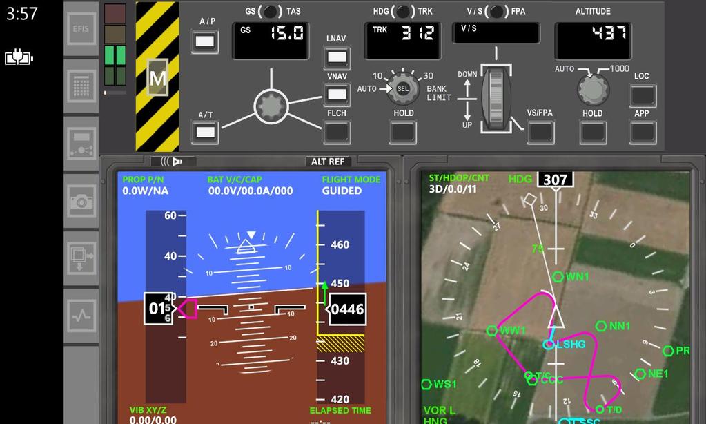
9 4 New Features 4.1 Overview over version Paradigm changes compared with version 1.5 The main feature of version 2.0 is the autopilot. Before (up until version 1.5) FlightZoomer only provided the instruments to the pilot, but no possibility to control the flight. Even following flight plans or capturing an ILS or VOR localizer had to be done manually using the RC transmitter. As a result, the accuracy left a lot to desire. With version 2.0 the focus has completely shifted to automatic flight. The capabilities of the 787 autopilot have largely been implemented. As following planned routes manually is not required/preferred anymore, a number of features became obsolete and some are not even supported anymore (see version 1.5 documentation to get the details): o Features that support to follow flight plans by manual flight (flight director) o Features that support a constant turn rate (test flight, RC transmitter configuration )Distinction between planned and actual route on the Navigation Display Usage of the phones internal sensors and GPS is not recommended anymore because the data received from the flight controller is so much more accurate. As a result, the system setup is simplified significantly and a number of mainly Sensorics features become obsolete (they are still there in case somebody wants to use the version 1.5 approach): o The attitude of the sensor device on the aircraft is no longer relevant, thus geometry capturing is no longer needed. o The same applies to the compass calibration as well. o The GPS of the phone is also no longer needed Functional changes compared with version 1.5 Beside the internal camera now also the Sony camera API is supported, which enables to control a wide variety of Sony cameras via WLAN. The camera is now controlled from the groundstation. Two modes can be controlled: start/stop shooting an image series and start/stop recording a video (supported both for the internal as for a Sony camera). Offline video download capabilities have been removed from FlightZoomer, because the recorded videos are now stored in the official picture library of the phone (version 1.5 was targeting an OS version, which did not support that yet, hence the in-built download feature). New GUI layout on the groundstation: o The selectable panel bar buttons have been replaced by static buttons on the left side of the screen. o Thinner instruments frames for the Primary Flight Display and the Navigation Display give more space for content. 9

 to select the desired information at any time by himself: o o The VOR L / R Selector")

10 o The buttons on the frame of the Navigation Display have become obsolete, or have been moved to the autopilot Mode Control Panel (MCP). In version 1.5 a somewhat limited logic automatically determined whether the Navigation Display showed the planned route or the localizer of a tuned ILS/VOR. In version 2.0 the pilot has to manually select these options on the DISPLAY CONTROL-panel. That way the pilot has the possibility (and responsibility) to select the desired information at any time by himself: o o The VOR L / R Selector allows to switch the localizer indications between the left and the right VORs (if both are tuned). The left ND rotary switch has two new positions: VOR and APP. Beside MAP or PLAN, which always show the flightplan route, VOR allows to display the localizer indications for a tuned VOR, while APP allows to show the localizer indications for a tuned ILS receiver. 10
11 4.2 Autopilot Functional aspects Overview over the autopilot modes The following table shows the 14 new autopilot modes grouped into three channels vertically and horizontally by three types of automatic flying modes: Channel BASIC modes RADIO NAVIGATION modes FLIGHT PLAN modes Track Over Ground select/hold VOR Localizer arm/capture/hold LNAV activate LATERAL Heading select/hold ILS Localizer arm/capture/hold Turn Rate select/hold Altitude arm/capture/hold ILS Glideslope arm/capture/hold VNAV activate VERTICAL Vertical Speed Flight Path Angle select/hold select/hold FLCH Flight Level Change activate SPEED Speed select/hold Flight Plan Speed select/hold Autopilot modes types There are three autopilot modes types: - The BASIC modes cover the basic flight trajectory in the three degrees of freedom. - The RADIO NAVIGATION modes enable capture and follow of simulated radio navigation aids from the navigation database. - The FLIGHT PLAN modes control the flight based on the defined or loaded flight plan. Autopilot mode states For each autopilot mode one or more states are applicable. The following states exist: States select/hold arm/capture/ hold activate Description Autopilot modes that offer these two states allow setting a target value which immediately becomes effective. Any previously active mode of the same channel is immediately deactivated. Autopilot modes that have these three states offer to set a target which first needs to be approached using another mode of the same channel. During that time the mode is in an armed state. The target is then automatically captured (with a soft transition), the previous mode becomes deactivated and the previously armed mode is put in the hold state. These modes have no target value and are just activated. Any previously active mode of the same channel is immediately deactivated. 11
12 Autopilot channels The three channels LATERAL, VERTICAL and SPEED are the degrees of freedom which are covered by similar autopilot modes. As long as the autopilot is engaged, one mode needs to be active for each channel. This means that this particular mode is in the state hold or activated. Additionally, for the two channels LATERAL and VERTICAL, a second mode can be in the state armed. As a result, the two channels LATERAL and VERTICAL basically are composite states which at any time can have two modes: One which is in the hold or activated state, and one which is in the armed state. The following tables shows all the possible combinations. The notation is <mode in hold or activated state> + <mode in armed state> These are all valid LATERAL composite states: With no armed mode Combinations with modes in armed state Track Over Ground + none Track Over Ground + VOR Localizer Track Over Ground + ILS Localizer Heading + none Heading + VOR Localizer Heading + ILS Localizer VOR Localizer + none ILS Localizer + none LNAV + none A special case is the Turn Rate-mode. Whenever the Track Over Ground- or the Heading-mode are active, the selected turn rate is applied too during the turns. These are all valid VERTICAL composite states: With no armed mode Combinations with modes in armed state Altitude + none Altitude + Altitude Altitude + ILS Glideslope Vertical Speed + none Vertical Speed + Altitude Vertical Speed + ILS Glideslope Flight Path Angle + none Flight Path Angle + Altitude Flight Path Angle + ILS Glideslope FLCH + none FLCH + Altitude ILS Glideslope + none VNAV + none Compatibility The FlightZoomer autopilot up to now is only supported and tested for multicopters (FlightZoomer Sensorics mated with Arducopter). Minimal version for Arducopter is 3.3. The integration for fixed wing operations is not yet completed (mating FlightZoomer Sensorics with Arduplane). 12

13 Processing of autopilot commands The following sequence diagram shows the processing of an autopilot command: A: Deactivated B: Activation Requested C: Activated The processing flow works as follows: 1. [A:] The autopilot view component in the Groundstation-app displays the activation state of each mode by lighting the button accordingly. Unlighted means deactivated. 2. [1:] The pilot modifies a parameter of the autopilot via the Mode Control Panel (e.g. a requests new mode). 3. [B:] The respective mode button turns white (= on) but the lower half of the button still has a red shade. 4. [1.1:], [1.1.1:] The command is sent to the Sensorics-app and stored in the autopilot processing component. 5. [ :] The autopilot considers the new parameter to control the flight path via MAVLINK. 6. [ :], The updated autopilot state is reported to the Groundstation-app. [ :] 7. [C:] The respective mode button turns fully white now and the red shade disappears. 13
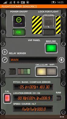
14 4.2.2 Groundstation-app While the implementation of the autopilot features is spread over both the Sensorics and the Groundstation, the interaction between the pilot and the system only happens at the groundstation. In this chapter the autopilot MCP (Mode Control Panel) is explained. Generally, it is recommended to train the autopilot features intensively with the simulation mode before actually using it with the aircraft Activation of the autopilot The activation of the autopilot is done by the autopilot master switch on the MCP. At any time, the autopilot can be activated or deactivated. Activating the autopilot will change the flight controller mode to GUIDED so that FlightZoomer can begin controlling the flight path. When the autopilot is being switched off, the flight mode will be set to POS_HOLD to overtake manual control again. If a different APM mode than GUIDED is set manually (e.g. using the RC transmitter) the FlightZoomer autopilot will be deactivated. Along with the activation of the autopilot goes the activation of the following default autopilot modes for each channel: - LATERAL: Track Over Ground hold - VERTICAL: Altitude hold - SPEED: Speed hold In each of the channels the momentary value is taken as the target value. The following user interface element is used to activate and deactivate the autopilot: 1 Autopilot (A/P) engage button Element 1 Autopilot (A/P) engage button Purpose This button is the master switch for the autopilot. The switch is shaded red in the lower half as long as the last request has not been acknowledged from the onboard device. 14
15 Speed-mode Mode type Channel Supported phases Overview Unit Target value range Supported combinations BASIC SPEED Select / Hold The Speed-mode controls the forward speed of the aircraft. It is the most basic autopilot mode because any other autopilot mode depends on it. Without having set a forward speed, no other mode will be effective except the two basic direction modes Heading and Track over ground. The Speed-mode is also called autothrottle because for fixed wing aircraft the throttle controls the speed. The target speed value is set and shown in display units. The display unit for speed can be defined either as m/s, knots, km/h or mph on the IDENT page of the FMS. Any positive value including 0.0 can be selected as target speed. The Speed-mode is only applicable if the autopilot operates in any of the BASICor RADIO NAVIGATION-modes. Using the LNAV-mode will select the target speed from the flight plan (see Flight Plan Speed-mode). The following transitions are possible to reach the Speed- mode: Autopilot switched off Speed Press AP Master switch / target speed = current Turn speed rotary selector / target speed = new value Speed Shortly pressing the speed rotary selector / target speed = 0 Speed LNAV Switch off LNAV / target speed = current LNAV Destination reached / target speed = 0 15
 button The autothrottle controls the forward speed.")

16 The following user interface elements are used to control the Speed-mode on the MCP: 1 Speed target window 3 Rotary speed selector 2 Autothrottle (A/T) button Element Purpose 1 Speed target window The speed target window shows the currently set target speed. The value is set using the rotary speed selector beneath it. 2 Autothrottle (A/T) button The autothrottle controls the forward speed. As the autothrottle currently is not supported independently of the autopilot, the state of this button at any time correlates with the A/P button state. 3 Rotary speed selector This selector defines the target speed in display unit. The following user interaction is supported: - Shortly pressing the knob Reset the target speed immediately to zero (emergency stop). - Pressing and holding the selector Pressing and holding the knob opens a zoomed version of the rotary selector, which allows selecting the target value by sliding with the finger around the center: 16
17 Track Over Ground-mode Mode type Channel Supported phases Overview Unit Target value range Supported combinations BASIC LATERAL Select / Hold The Track Over Ground-mode is the default lateral mode. It controls the direction of the flight path over ground. This means that a bank angle is applied to counter the effect of any crosswind component. The target direction is set and shown in degrees. The number range for the target direction is n/a The following transitions are possible to reach the Track Over Ground- mode: Autopilot switched off Heading Press AP Master switch / target direction = current Press Reference switch [HDG] Reference switch [TRK] VOR Localizer or ILS Localizer or LNAV VOR Localizer or ILS Localizer or LNAV Track Over Ground Press direction HOLD button / target direction = current Turn direction rotary selector / target direction = new value Turn direction rotary selector / target direction = new value [HDG] Reference switch [HDG] Reference switch [TRK] [TRK] Track Over Ground LNAV Destination reached / target direction = current 17


18 The following user interface elements control the Track Over Ground-mode on the MCP: Heading/track reference switch 1 2 Direction target window Rotary direction selector 3 4 Direction HOLD button Element 1 Heading/track reference switch 2 Direction target window 3 Rotary direction selector Purpose This button toggles between the Track over ground-mode and the Headingmode. The direction target window shows the currently selected target direction. In addition, a text label indicates the variation of the direction mode (TRK for Track over ground, HDG for Heading). This selector defines the target direction. The following user interaction is supported: - Pressing and holding the selector opens a zoomed version of the rotary selector: 4 Direction HOLD button - On the zoomed selector the target value can be chosen by sliding with the finger around the center. - Sliding along the outer track (red arrows) will set the target direction directly according to the compass rose. This means that the position of the finger directly matches the resulting target direction (up = 0, right = 90, down = 180, left = 270 ). - Sliding along the inner track (yellow arrows) will continuously increase or reduce the target value, allowing a fine tuning to the desired target direction. This button enables an immediate hold of the current direction (either Track Over Ground or Heading, depending on the selected variation). This is possible at any time and coming from any other lateral mode. Whenever one of the two basic direction hold modes is active, this button becomes illuminated. 18
19 Heading-mode Mode type Channel Supported phases Overview BASIC LATERAL Select / Hold The Heading-mode is an alternative to the Track Over Ground-mode. It controls only the direction of the nose of the aircraft. This means that the target direction will differ from the actually flown flight path over ground if there is a crosswind component. In manned aviation the Heading-mode is more often used than the Track Over Ground-mode. Typically, whenever Air Traffic Control provides vectors for an approach, they will request an aircraft to hold a particular heading. Unit Target value range Supported combinations For RC aircraft on the other hand the Track Over Ground is considered as the default mode because even with moderate crosswind the sideward drift becomes notable using the Heading-mode. The target direction is set and shown in degrees. The number range for the target direction is n/a The following transitions are possible to reach the Heading-mode: Autopilot switched off Track Over Ground Press AP Master switch / target direction = current Press Reference switch [TRK] Reference switch [HDG] VOR Localizer or ILS Localizer or LNAV VOR Localizer or ILS Localizer or LNAV Heading Press direction HOLD button / target direction = current Turn direction rotary selector / target direction = new value Turn direction rotary selector / target direction = new value [TRK] Reference switch [TRK] Reference switch [HDG] [HDG] Heading 19
20 For the description of the user interface elements please refer to the previous chapter about the Track Over Ground-mode Turn Rate-mode Mode type Channel Supported phases Overview Unit BASIC LATERAL Select / Hold The turn rate determines how quickly the aircraft turns to the right or to the left. For a given forward speed, it also directly determines the turn radius. FlightZoomer supports setting the target turn rate to either AUTO or one of five distinct target values: AUTO 5 /s 10 /s 20 /s 30 /s 60 /s The turn rate is taken from the standard turn rate, which is configured in the aircraft settings A turn rate of 5 degrees per second; results in very wide and gentle turns A turn rate of 10 degrees per second; results in a moderate turn A turn rate of 20 degrees per second; typical default turn rate A turn rate of 30 degrees per second; turns a bit more aggressive A turn rate of 60 degrees per second; definitely would spill the passengers coffee if there were any. Target value range Supported combinations n/a The selected turn rate becomes immediately effective as soon, as one of the basic direction modes becomes active (Track Over Ground or Heading). The selected turn rate is not applied to any other of the lateral modes. The radio navigation modes and the flight plan modes calculate turns based on the standard turn rate, which has been configured in the aircraft settings (Sensorics app). 20
21 The following user interface elements are used to control the Turn Rate-mode on the MCP: Decrease turn rate 1 2 Increase turn rate Element Purpose 1 Decrease turn rate Tapping on the area to the left of the direction rotary selector, selects the next lower turn rate setting. The resulting setting is indicated by the selector as follows: AUTO 5 /s 10 /s 20 /s 30 /s 60 /s 2 Increase turn rate Tapping on the area to the right of the direction rotary selector, selects the next higher turn rate setting. See above how the various settings are indicated. 21
22 Altitude-mode Mode type Channel Supported phases Overview Unit Target value range Supported combinations BASIC VERTICAL Arm / Capture / Hold The Altitude-mode can be armed independently of the current vertical mode and climb rate by setting a target altitude. After setting a target altitude one of the other basic vertical modes needs to be used to capture the armed altitude. The transition to level flight (while capturing the target altitude) is done by applying a steady deceleration of 0.5 m/s 2 Display unit for altitudes (can be ft or m), the target altitude is defined in AMSL Unlimited See diagram below The following transitions are possible to reach the Altitude-mode. The diagram shows composite states for the vertical channel, highlighting both the active (HOLD) and the armed (ARMED) mode: Vertical channel HOLD: Altitude ARMED: - Turn rotary altitude selector / target altitude = new value Vertical channel HOLD: Altitude ARMED: Altitude Vertical channel HOLD: Vertical Speed ARMED: - Vertical channel HOLD: Flight Path Angle ARMED: - Autopilot switched off Turn rotary altitude selector / target altitude = new value Turn rotary altitude selector / target altitude = new value Press AP Master switch / target altitude = current Vertical channel HOLD: Vertical Speed ARMED: Altitude Vertical channel HOLD: Flight Path Angle ARMED: Altitude Vertical channel HOLD: Vertical Speed or Flight Path Angle or FLCH ARMED: Altitude Target altitude reached Vertical channel HOLD: Altitude ARMED: - Vertical channel HOLD: Vertical Speed or Flight Path Angle or FLCH ARMED: Altitude or - Press altitude HOLD button 22

23 The following user interface elements are used to control the Altitude-mode on the MCP: Altitude target window 1 Rotary altitude selector 3 Altitude HOLD button 4 Element 1 Altitude target window 2 Rotary altitude selector Purpose The altitude target window shows the currently selected target altitude. The target value is set using the rotary selector beneath it. The displayed value represents at any time the autopilot target altitude, or, while the VNAV-mode is active, the flight plan cruise altitude. With this selector a target altitude can be defined in display unit. The following user interaction is supported: - Pressing and holding the selector Pressing and holding the knob opens a zoomed version of the rotary selector, which allows selecting the target value by sliding with the finger around the center: 3 Altitude HOLD button The altitude HOLD button enables an immediate hold at the current altitude. This is possible at any time and coming from any other vertical mode. This button is not yet illuminated while the Altitude-mode is in armed state. Only after the Altitude-mode is in hold state, the button becomes illuminated. 23
24 Vertical Speed-mode Mode type Channel Supported phases Overview Unit Target value range Supported combinations BASIC VERTICAL Select / Hold The Vertical Speed-mode applies a constant climb or descend speed. This means that the resulting climb or descend angle varies with the forward speed. The target vertical speed is entered in display unit per minute (thus can be ft/min or m/min). The divider is borrowed from real aviation, where the altitude change per minute allows for easy vertical flight profile estimations. Unlimited n/a The following transitions are possible to reach the Vertical Speed-mode: Flight Path Angle Press Reference switch FLCH or VNAV Press VS/FPA button / target_vertical_spd = current [FPA] [VS] Vertical Speed Reference switch Altitude or FLCH or VNAV Move VS/FPA thumb wheel / target_vertical_spd = new value [FPA] Reference switch [VS] 24

25 The following user interface elements are used to control the Vertical Speed-mode on the MCP: VS/FPA reference switch 1 2 VS/FPA target window VS/FPA thumbwheel selector 3 4 VS/FPA button Element 1 VS/FPA reference switch Purpose This button toggles between the Vertical Speed-mode and the Flight Path Angle-mode. 2 VS/FPA target window The VS/FPA target window shows the currently selected target value for either the Vertical Speed-mode or the Flight Path Angle-mode. In addition, a text label indicates the variation (VS for Vertical Speed, FPA for Flight Path Angle). 3 VS/FPA thumbwheel selector This selector defines the target vertical speed or flight path angle. The following user interaction is supported: - Tap on the thumbwheel and slide upwards or downwards to set a new target. The whole vertical space of the touchscreen can be used to slide. 4 VS/FPA button Pressing this button holds the current climb or descend gradient (either Vertical Speed or Flight Path Angle, depending on the selected variation). Whenever one of the two modes is active, this button becomes illuminated. 25
26 Flight Path Angle-mode Mode type Channel Supported phases Overview Unit Target value range Supported combinations BASIC VERTICAL Select / Hold The Flight Path Angle-mode applies a constant climb or descend angle. This means that the resulting climb or descend speed varies with the forward speed. The flight path angle is defined in degrees. The number range for the target flight path angle is n/a The following transitions are possible to reach the Vertical Speed-mode: Vertical Speed Press Reference switch FLCH or VNAV Press VS/FPA button / target_flight_path_angle = current [VS] Reference switch [FPA] Flight Path Angle Altitude or FLCH or VNAV Move VS/FPA thumb wheel / target_flight_path_angle = new value [VS] Reference switch [FPA] For the description of the user interface elements please refer to the previous chapter about the Vertical Speed-mode. 26
27 FLCH-mode Mode type Channel Supported phases Overview Unit Target value range Supported combinations BASIC VERTICAL Activate The FLCH-mode immediately initiates a climb or descend to an armed target altitude (FLCH means flightlevel change). This is the most convenient way to initiate climbs or descends. In full scale aviation, this mode uses energy management to calculate the most economic climb or descend speed (by setting either the throttle either to idle for descending or CLIMB THRUST for climbing). FlightZoomer however does not calculate the climb/descend gradient based on energy calculations. Instead a constant climb/descend rate is applied, which can be configured in the aircraft settings. The regular vertical speed (defined in the aircraft settings), which is used for the FLCH-mode, is specified in m/s. Unlimited It is a precondition for the FLCH-mode, that an altitude has been armed. The following transition is possible to reach the FLCH-mode: Vertical channel HOLD: Altitude or Vertical Speed or Flight Path Angle ARMED: Altitude Press FLCH button Vertical channel HOLD: FLCH ARMED: Altitude The following user interface elements are used to control the FLCH-mode on the MCP: FLCH button 1 Element Purpose 1 FLCH button Pressing this button triggers the FLCH-mode. Whenever the FLCH-mode is active, this button becomes illuminated. 27
28 VOR Localizer-mode Mode type Channel Supported phases Overview RADIO NAVIGATION modes LATERAL Arm / Capture / Hold The VOR Localizer-mode allows to arm, capture and hold a VOR radial: Selected radial 107 capturing Selected VOR armed Flight path(s) VOR Localizer-mode hold As a precondition, the VOR must have been defined in the navigation database. The VOR can be tuned (red box below) and the radial can be selected (yellow box below) on the NAV RAD page of the FMS. The VOR Localizer-mode only supports the left receiver (VOR L): The turn rate for capturing the radial is the standard turn rate from the aircraft settings. The VOR Localizer-mode allows to fly on a radial towards a VOR and past a VOR. The mode stays in the armed state while approaching the radial. Once a radial is captured and as long as the lateral autopilot mode is not changed, the aircraft holds the radial until the end of the earth If the selected radial is behind the current position, the VOR Localizer-mode will stay in armed state forever (to be precise after a straight flight one time around the globe, the radial will be found ahead of the aircraft and be captured ;-). Note: In manned aviation, VOR based navigation was heavily used in the early days of IFR flying. Today RNAV has replaced the classic VOR-to-VOR way of flying. RNAV waypoints can not only be VORs but freely placed navigation fixes without radio station. The FlightZoomer autopilot mode which represents RNAV flying is the LNAV-mode. And to be really precise, the LOC-button on the real 787 does not support following VOR radials as implemented by FlightZoomer at all. In modern jets, like the 787, the VOR Localizer mode is restricted to VOR approaches, where the VOR, like an ILS, has a directed beam (called localizer) to allow high precision lateral guidance towards a runway. Therefore, the implementation in FlightZoomer 28
29 Unit Target value range Supported combinations actually recreates the functionality of the VOR/LOC button, which is present in older jets, like the 737. The radial can be defined in on the NAV RAD FMS page. n/a The VOR Localizer-mode allows capturing a radial only coming from one of the two basic lateral modes, Track Over Ground or Heading. The following transitions are possible to reach the VOR Localizer-mode (armed or hold): Lateral channel HOLD: Track Over Ground Lateral channel HOLD: Heading ARMED: - ARMED: - Press LOC button / radial and station from NAV RAD FMS page Press LOC button / radial and station from NAV RAD FMS page Lateral channel HOLD: Track Over Ground Lateral channel HOLD: Heading ARMED: VOR Localizer ARMED: VOR Localizer Lateral channel HOLD: Track Over Ground or Heading ARMED: VOR Localizer Radial of armed VOR reached Lateral channel HOLD: VOR Localizer ARMED: - The following user interface elements are used to control the VOR Localizer-mode on the MCP: LOC button 1 Element Purpose 1 LOC button Pressing this button triggers the VOR Localizer-mode. Whenever the VOR Localizer-mode is active, this button becomes illuminated. 29
30 ILS Localizer-mode Mode type Channel Supported phases Overview RADIO NAVIGATION modes LATERAL Arm / Capture / Hold The ILS Localizer-mode is used for automatic approaches to a runway and works very similar like the VOR Localizer-mode. A difference between the VOR Localizer- and ILS Localizer-mode is, that an ILS station has both vertical and lateral radio beams, that guide an aircraft to a runway. This means that there is no radial, which freely can be selected. Instead the direction of the runway is the selected automatically as the (only possible) radial to be followed. While there is no predetermined order in which the vertical and the horizontal beam should be captured, typically first the localizer is captured before the glideslope closes in from above. As a precondition for an ILS approach, the ILS must have been defined in the navigation database. The ILS frequency of the runway, which is used for the landing, can be tuned on the NAV RAD page of the FMS: The turn rate for capturing the ILS is the standard turn rate from the aircraft settings. Another property, which is defined in the aircraft settings, is the behavior at the end of the approach. The available options allow to let the aircraft stop and keep the position at the runway threshold (recommended for multicopters) or to continue the descend gradient infinitely. The latter would let land a fixed wing aircraft on a sufficiently spaced landing strip. Without a flare phase though, but it needs to be considered that landing at the standard ILS glide angle of 3 without flaring is SOP (standard operating procedure) under certain (weather-) conditions even for the largest jets. FlightZoomer approaches can be defined with any glide angle (when the navigation database is created using the relay server application). So having rather shallow glide angles of 3 or 4 at maximum is not only realistic but also perfectly feasible in order to let fixed wing aircraft land automatically. For multicopters the ILS approach works well for glide angles up to 15 or

31 Unit Target value range Supported combinations n/a n/a The ILS Localizer-mode always goes along with the ILS Glideslope-mode. Tuning the radio receiver to an ILS frequency and pressing the APP button on the MCP always activates both of these modes. The following transitions are possible to reach the ILS Localizer-mode (armed or hold): Lateral channel HOLD: Track Over Ground Lateral channel HOLD: Heading ARMED: - ARMED: - Press APP button / ILS frequency selected at NAV RAD FMS page Press APP button / ILS frequency selected at NAV RAD FMS page Lateral channel HOLD: Track Over Ground Lateral channel HOLD: Heading ARMED: ILS Localizer ARMED: ILS Localizer Lateral channel HOLD: Track Over Ground or Heading ARMED: ILS Localizer Extended runway center line reached Lateral channel HOLD: ARMED: ILS Localizer - The following user interface elements are used to control the ILS Localizer-mode on the MCP: APP button 1 Element Purpose 1 APP button Pressing this button triggers the ILS Localizer-mode. Whenever the ILS Localizer-mode is active, this button becomes illuminated. 31
32 ILS Glideslope-mode Mode type Channel Supported phases Overview Unit Target value range Supported combinations RADIO NAVIGATION modes VERTICAL Arm / Capture / Hold The ILS Glideslope-mode captures an armed ILS for the vertical channel and holds the glideslope during the descend to the runway threshold. This mode can only be activated in combination with the ILS Localizer-mode. Refer also to the description for the ILS Localizer-mode to see some common remarks about ILS approaches. The ILS Glideslope-mode can only be in armed state below the glideslope. If the APP button is pressed while at or above the glideslope, the mode immediately changes to the capture and later to the hold state. To safely and smoothly capture the glideslope, the aircraft should also be in level flight while approaching the glideslope. The flight segments up to the final approach should be executed in a way, that complies with the two mentioned requirements (catch the glideslope from below and catch it in level flight). n/a n/a See ILS Localizer-mode The following transitions are possible to reach the ILS Glideslope-mode. The diagram shows composite states for the vertical channel, highlighting both the active (HOLD) and the armed (ARMED) mode: Vertical channel HOLD: Altitude ARMED: - Press APP button / ILS frequency selected at NAV RAD FMS page Vertical channel HOLD: Altitude ARMED: ILS Glideslope Vertical channel HOLD: Altitude ARMED: ILS Glideslope Glideslope reached from below in level flight Vertical channel HOLD: ARMED: ILS Glideslope - For the description of the user interface element please refer to the previous chapter about the ILS Localizer-mode. 32
33 LNAV-mode Mode type Channel Supported phases Overview FLIGHT PLAN modes LATERAL Activate The LNAV-mode controls the lateral channel to follow a planned route. Before the LNAV-mode can be activated, a route has to been entered on the RTE page of the Flight Management System (optionally also by loading a stored route). A planned route has a specified cruise speed and cruise altitude. The cruise speeds in combination with the standard turn rate determines the radius of each turn. The cruise altitude is used calculate the vertical flight profile (see VNAV-mode). The LNAV-mode can be activated from any location. The aircraft will turn to the first waypoint of the route and continue to follow the planned route from there on. At the end of the route the aircraft stops and holds the position. The turn rate, which is applied for right and left turns, cannot be controlled using the Turn Rate-mode on the fly (because the turn radius would not be predictable as a result). Instead the standard turn rate is used, which can be specified in the aircraft settings (Sensorics app): Unit Target value range Supported combinations n/a n/a The LNAV-mode can be used in combination with any vertical mode, except the ILS Glideslope-mode. This means that the usage of VNAV-mode is not mandatory (though recommended). 33


34 The following transitions are possible to reach the LNAV -mode: Track Over Ground or Heading or VOR Localizer Press LNAV button LNAV The following user interface elements are used to control the LNAV-mode on the MCP: 1 LNAV button Element Purpose 1 LNAV button Pressing this button triggers the LNAV-mode. Whenever the LNAV-mode is active, this button becomes illuminated VNAV-mode Mode type Channel Supported phases Overview FLIGHT PLAN modes VERTICAL Activate The VNAV-mode controls the vertical channel to follow a planned route. The VNAV-mode can only be switched on while the LNAV-mode has already been activated. This means that the LNAV-mode can also be used without activating the VNAV-mode (using any of the basic vertical modes instead for the vertical channel). A planned route has a specified cruise altitude which determines the vertical flight profile. Based on the vertical flight profile T/C- and T/D points are calculated (top of climb and top of descend) and shown on the ND. If the initial altitude is above the cruise altitude, instead of the T/C point a E/D points is calculated (end of descend). 34

35 If the cruise altitude cannot be reached (e.g. the route has not enough length totally), a T/C/D point will be calculated, where climb directly is followed by the descend towards the destination. If an ILS is tuned the ILS glideslope capture altitude is taken as target altitude at the destination. The climb and descend rate for the VNAV vertical flight profile is taken from aircraft settings (Sensorics app): Unit Target value range Supported combinations n/a n/a The VNAV-mode requires the LNAV-mode to be active, before it can be activated. The following transitions are possible to reach the VNAV-mode: Altitude or Vertical Speed or Flight Path Angle or FLCH Press VNAV button VNAV 35

36 The following user interface elements are used to control the VNAV-mode on the MCP: 1 VNAV button Element Purpose 1 VNAV button Pressing this button triggers the VNAV-mode. Whenever the VNAV-mode is active, this button becomes illuminated Flight Plan Speed-mode Mode type Channel Supported phases Overview FLIGHT PLAN modes SPEED Implicate activation For the LNAV-mode the speed is specified in the flightplan. This mode automatically holds the flightplan cruise speed as long as LNAV is switched on. The LNAV target speed is defined on the first RTE page in the FMS: Unit Target value range Supported combinations The target speed value is set and shown in display units. The display unit for speed can be defined either as m/s, knots, km/h or mph on the IDENT page of the FMS. Any positive value including 0.0 can be selected as target speed. This mode automatically engages and disengages with the LNAV-mode. 36
37 4.3 Simulation Overview over the simulation features Beside the still existing, Relay Server based simulation, two new simulation feature has been implemented in the groundstation, that allows completely autonomous usage of the autopilot. The following diagrams show the possibilities. A. Relay server induced basic aircraft movements simulation Existing, see version 1.5 documentation. Sensor device Pos, Spd, Crs entered via GUI or Joystick Groundstation B. Autopilot simulation New, see chapter Optionally online *) Sensor device Relay Server Autopilot, generates simulated 3D flight vectors Ground-station *) For initial load of the navigation database (only once required) and to access stored flight plans 37


38 C. Air Traffic Control simulation New, see chapter Autopilot Sensor device Relay Server ATC Simulation Ground-station Autopilot simulation On the welcome page, the checkbox simulation allows to start the app in simulation mode: The simulation mode covers the complete end-to-end processing chain from the autopilot GUI, to the autopilot controlling, to the physics of a simulated multicopter and back. It is intended for training and demonstration purposes. In simulation mode the ground station simulates the overall system reaction, when using the autopilot. Most of the autopilot features can be used without any preparation. The simulation mode works just like a backend behind the existing ground station functionality. There are two ways, how the simulation mode can be used: either the groundstation in combination with the relay server (online) or the groundstation completely stand-alone (offline). If the connection to the relay server cannot be established after 8 seconds, the simulation switches to offline. 38
39 The following limitations for the simulation mode exist: Limitation Navigation Database Store and load flight plans (CO ROUTE) Aircraft Settings Initial location Online operation (in combination with the relay server) The simulation mode does not deviate from the normal behavior (the most current navigation database is just automatically loaded at app start). The simulation mode does not deviate from the normal behavior (flight plans can be stored/loaded to/from the relay server). Offline operation (Entirely stand-alone) After failing to connect to the relay server for 8 seconds, the entire navigation database is loaded from locally cached copy. It always reflects the state, that was current when connecting the last time to the relay server. (this means also, that no navigation database is available, if the groundstation app has not at least once been connected to the relay server). Accessing the stored flight plans on the relay server is not supported. This limitation does not make a big difference though because creating routes on the fly is possible without restrictions. The source of the aircraft settings is the Sensorics-app. These settings are replicated and cached locally on the Groundstation app. If present, the cached aircraft settings are used for the simulation mode. If not, default settings are used: Flight-number (ATC call sign) = Flightzoomer 1 Copter = true Stop after ISL approach = true Standard climb speed = 1.3 m/sec Standard turn rate = 15 /sec In simulation mode the aircraft initially is positioned at the FlightZoomer flight test range in Switzerland. The position can be moved to any location by loading or creating a flightplan. If that is done the simulated location is moved to the origin of the flight plan. Procedure to use the simulation mode: 1. Check the simulation-checkbox before entering the cockpit. 2. Confirm the warning popup. 3. If the configured relay server can be reached, the navigation database is loaded, and the simulation can begin (using the autopilot). 4. If the configured relay server cannot be reached, the navigation database is loaded from local cache. 5. Use the autopilot by activating it. 6. Use the basic/radio navigation/flight plan autopilot modes. Also the Air Traffic Control Simulation is supported. It is recommended to deeply become acquainted with the autopilot using the simulation mode before actually taking off with the real aircraft. 39

40 4.3.3 Air Traffic Control simulation Using the in-built speech synthesis, FlightZoomer offers the possibility to simulate instructions from a virtual air traffic control center. The air traffic simulation feature has the following capabilities: - The instructions of a virtual air traffic officer are simulated with a female voice - Each instruction is read back by a male voice, simulating the pilot, who acknowledges anything spoken also in real world aviation. This gives you the chance, to hear the instruction a second time. - The feature is only available for the approach phase of a flight at the moment. - Air traffic control guidance can be engaged during the flight at any time and at any location. - Depending on the current altitude and location a target altitude is instructed (which is the ILS capturing altitude) and directions are given, to fly a realistic approach pattern (downwind, base and final approach). - The call sign can be defined in the aircraft settings (the default value is Flightzoomer 1 ). Procedure to use the Air Traffic Control simulation: 1. Ensure, that the ILS receiver is tuned to the frequency of a runway from the navigation database 2. Engage the air traffic control feature. Tap on the indicated area on the navigation display: 3. The synthetic male voice of you (the pilot) immediately contacts approach control. 4. The air traffic controller (female) replies to the request and starts guiding you to the runway. 5. Engage and set the altitude and heading or track hold autopilot modes as instructed, to be vectored to the ILS. 40
41 The following set of clearances and instructions exist: First contact Lateral guidance Vertical guidance ILS clearance Landing clearance by the pilot reply by ATC by ATC confirmation by the pilot by ATC confirmation by the pilot by ATC confirmation by the pilot by ATC confirmation by the pilot <call sign>, contact <airport name> approach <call sign>, this is <airport name> approach, <lateral guidance>, <vertical guidance>, expect vectors ILS runway <selected runway ID> <call sign>, Turn right/left to <new target direction> degrees Turn right/left to <new target direction> degrees, <call sign> <call sign>, Climb/descend to <new target altitude> Climb/descend to <new target altitude>, <call sign> <call sign>, Cleared for ILS approach, runway <runway ID> Cleared for ILS approach, runway <runway ID>, <call sign> <call sign>, Cleared to land, <runway ID>, have a good day! Cleared to land, <call sign>, bye, bye Note: to add realism, the ATC simulation feature is programmed to vary these instructions slightly (only the buffer words, the content is strictly reproduced). It is recommended to use the simulation mode to get acquainted with the ATC simulation feature. 4.4 Camera control New camera features: - The internal camera (either front or back) of the sensor device can be controlled from the ground station - These features are covered: o start/stop recording a video o start/stop taking an image series - Either the front- or the back-camera can be used - Any orientation of the camera can be configured - The video or images are captured with the best resolution - Additionally, the Sensorics-app now supports the interactivity with the Sony camera API - The Sony camera needs to be connected to the sensor device using WLAN and will automatically be detected - With the Sony camera the same features can be used as with the internal camera - Shooting an image series both with the internal and the Sony camera works as follows: o Activate the image series camera mode on the groundstation o The configured camera(s) (can be either of the internal cameras and/or a connected Sony camera) start(s) capturing images with the shortest possible interval o The interval depends only on the time the camera needs to make one shoot o The images of the internal camera are stored in the picture library of the phone 41

42 Discontinued version 1.5 features: - Recording automatically an image series or a video as long as the sensor device is in LOCKED-mode - Changing the resolution of the internal camera - Having to download the captured videos from the sensor device to the groundstation Sensorics-app The Sensorics-app now supports the interactivity with a Sony camera API that just needs to be connected via WiFi with the onboard device. The camera must support the standard WiFi camera API (there is a long list of supported models on the Sony homepage). The following screen in the Sensorics app allows to select the camera which shall be used. The usage is selfexplanatory: Supported features Sony camera (external) Series shutter video recording Controlled from the ground station Phone camera (internal) Series shutter video recording Controlled from the ground station Supports either main (=back) or front camera Resolution Default setting Best available resolution Rotation Defined by installation Can be chosen on the cameras-page. The selected setting is stored in the app settings. 42
43 4.4.2 Groundstation-app If any camera has been selected in the Sensorics app, it can be controlled from the groundstation using the following sub panel: Description 1 Here the camera is deactivated Camera control panel 2 Using the SERIE SHUTTER start button, the camera starts shooting one image after another. The frequency depends on the capabilities of the camera. 3 Using the VIDEO start button, the camera starts recording a video. 43


44 4.5 Aircraft settings Sensorics-app The aircraft settings can easily be used to tailor the system behavior to match a particular setup or according to personal preferences. As these basically are attributes that apply to a particular aircraft, the definition happens on the Sensorics-app, which runs aboard the aircraft. Consequently, these settings need to be fixed on the ground, after being airborne they can t change anymore. The settings page can be opened in the Sensorics-app with the respective menu: Settings 1 Registration ID/Flight Number Purpose This string defines the unique ID of a flight within a FlightZoomer network. The string is also used as call sign for the Air Traffic Controller simulation. You can either choose real airline names and flight numbers if you like (e.g. American 94, United 100, Lufthansa 1234 and so on) or just any other call sign you want. Default is <Flightzoomer 1> 2 Aircraft type Currently only Multirotor is supported for automatic flight. Default value is Multicopter. 3 Stop at the end of an ILS approach This option allows to let the aircraft terminate an ILS approach at the runway threshold (recommended for multicopters) or to continue the descend gradient infinitely. The latter would let land a fixed wing aircraft on a sufficiently spaced landing strip. Without a flare phase though, but it needs to be considered that landing at the standard ILS glide angle of 3 without flaring is SOP (standard operating procedure) under certain (weather-) conditions even for the largest jets. FlightZoomer approaches can be defined with any glide angle (when the navigation database is created using the relay server application). So having rather shallow glide angles of 3 or 4 at maximum is not only 44
45 realistic but also perfectly feasible in order to let fixed wing aircraft land automatically. Default value is Checked. 4 Regular vertical speed This is the standard climb or descend rate. This figure is used for autopilot modes, where the climb rate is not specified specifically, like the FLCH- or VNAV-mode. Default value is 1.3 m/s. 5 Standard turn rate This is the standard turn rate. This figure is used for autopilot modes, where the turn rate is fixed, like the VOR Localizer-, ILS Localizer- or LNAV-modes. Default value is 1.3 m/s Groundstation-app Any time a connection between the sensor device and the groundstation is established, the aircraft settings are replicated to the Groundstation-app and locally stored. 4.6 Flight logs generated as Excel files Relay Server Application Another area, that was improved for version 2.0 is the automatic log file generation. Earlier the relay server automatically generated a comma separated file during the time, the system ran in LOCKED-mode (= Armed in Ardupilot terminology). With version 2.0 the comma separated file is still generated (to be used for the replay file feature). Additionally, the relay server generates a full-fledged Excel document, that contains of course the raw flight data, but also flight summary data and some charts. Using the Excel document and normal spreadsheet operations, any thinkable data analysis and presentation can easily be achieved. 45
: An example of a chart (altitude tab):")
46 An example of a flight summary (flight stats tab): An example of a chart (altitude tab): 46
Dash8 - Q400 - Autoflight
 12.3.1 Introduction The Automatic Flight Control System (AFCS), provides fail-safe operation of flight director guidance, autopilot, yaw damper and automatic pitch trim functions. 12.3.2 General The Automatic
Dash8-200/300 - Automatic Flight AUTOMATIC FLIGHT CONTROLS AND INDICATORS. Page 1
 AUTOMATIC FLIGHT CONTROLS AND INDICATORS FLIGHT GUIDANCE MODE SELECTORS (alternate action) - Engages flight director modes of operation. - Flight director command bars display lateral and/or vertical guidance
GRT Autopilot User Guide. All GRT EFIS Systems
 All GRT EFIS Systems Revision A 22-May-2014 Copyright 2014 3133 Madison Ave. SE Wyoming, MI 49548 (616) 245-7700 www.grtavionics.com Revision Notes Revision Date Change Description A 22-May-2014 Complete
This page is intentionally blank. GARMIN G1000 SYNTHETIC VISION AND PATHWAYS OPTION Rev 1 Page 2 of 27
 This page is intentionally blank. 190-00492-15 Rev 1 Page 2 of 27 Revision Number Page Number(s) LOG OF REVISIONS Description FAA Approved Date of Approval 1 All Initial Release See Page 1 See Page 1 190-00492-15
Fokker 50 - Automatic Flight Control System
 GENERAL The Automatic Flight Control System (AFCS) controls the aircraft around the pitch, roll, and yaw axes. The system consists of: Two Flight Directors (FD). Autopilot (AP). Flight Augmentation System
11 Traffic-alert and Collision Avoidance System (TCAS)
") 11 Traffic-alert and Collision Avoidance System (TCAS) INSTRUMENTATION 11.1 Introduction In the early nineties the American FAA stated that civil aircraft flying in US airspace were equipped with a Traffic-alert
11 Traffic-alert and Collision Avoidance System (TCAS) INSTRUMENTATION 11.1 Introduction In the early nineties the American FAA stated that civil aircraft flying in US airspace were equipped with a Traffic-alert
Digiflight II SERIES AUTOPILOTS
 Operating Handbook For Digiflight II SERIES AUTOPILOTS TRUTRAK FLIGHT SYSTEMS 1500 S. Old Missouri Road Springdale, AR 72764 Ph. 479-751-0250 Fax 479-751-3397 Toll Free: 866-TRUTRAK 866-(878-8725) www.trutrakap.com
SECTION 2-19 AUTOPILOT
 AIRPLANE SECTION 2-19 Block General...2-19-05...01 Automatic Flight Control System...2-19-05...02 Flight Guidance System...2-19-05...04 Flight Director...2-19-05...04 Autopilot...2-19-05...04 Flight Director
EMBRAER 135/145 Autopilot
 EMBRAER 135/145 Autopilot GENERAL The Primus 1000 (P-1000) Automatic Flight Control System (AFCS) is a fully integrated, fail passive three-axis flight control system which incorporates lateral and vertical
VOR/DME APPROACH WITH A320
 1. Introduction VOR/DME APPROACH WITH A320 This documentation presents an example of a VOR/DME approach performed with an Airbus 320 at LFRS runway 21. This type of approach is a non-precision approach
Operating Handbook For FD PILOT SERIES AUTOPILOTS
 Operating Handbook For FD PILOT SERIES AUTOPILOTS TRUTRAK FLIGHT SYSTEMS 1500 S. Old Missouri Road Springdale, AR 72764 Ph. 479-751-0250 Fax 479-751-3397 Toll Free: 866-TRUTRAK 866-(878-8725) www.trutrakap.com
MGL Avionics. Odyssey/Voyager G2 and iefis
 MGL Avionics Odyssey/Voyager G2 and iefis Navigation This document applies to G2 version 1.1.0.1 or later, iefis 1.0.0.3 or later. Note: This document is based on the G2. The iefis system provides identical
Digiflight II SERIES AUTOPILOTS
 Operating Handbook For Digiflight II SERIES AUTOPILOTS TRUTRAK FLIGHT SYSTEMS 1500 S. Old Missouri Road Springdale, AR 72764 Ph. 479-751-0250 Fax 479-751-3397 Toll Free: 866-TRUTRAK 866-(878-8725) www.trutrakap.com
SkyView. Autopilot In-Flight Tuning Guide. This product is not approved for installation in type certificated aircraft
 SkyView Autopilot In-Flight Tuning Guide This product is not approved for installation in type certificated aircraft Document 102064-000, Revision B For use with firmware version 10.0 March, 2014 Copyright
Basic GPS Operation. by Greg Whiley. Another practical publication from Aussie Star Flight Simulation
 Basic GPS Operation by Greg Whiley Another practical publication from Aussie Star Flight Simulation INTENTIONALLY LEFT BLANK Aussie Star Flight Simulation 2 Basic GPS Operations Statement of copyright
- FlightGear Autopilot and Route-Manager -
 - FlightGear 747-400 Autopilot and Route-Manager - General This documentation is valid for the version of 747-400 from 'buster' (http://flightgear.azuana.de). Our aircraft can be controlled by two different
How to Intercept a Radial Outbound
 How to Intercept a Radial Outbound by Greg Whiley Another practical publication from Aussie Star Flight Simulation How to intercepting a radial outbound 1 Greg Whiley Aussie Star Flight Simulation How
Instrument Flight Procedures - Glass Cockpits
 Instrument Flight Procedures - Glass Cockpits The concepts contained here are general in nature and can be used by all however, they are targeted toward glass cockpits and, more specifically, integrated
NAVIGATION INSTRUMENTS - BASICS
 NAVIGATION INSTRUMENTS - BASICS 1. Introduction Several radio-navigation instruments equip the different airplanes available in our flight simulators software. The type of instrument that can be found
FAA APPROVED AIRPLANE FLIGHT MANUAL SUPPLEMENT FOR. Trio Pro Pilot Autopilot
 Page 1 480 Ruddiman Drive TRIO AP Flight Manual Supplement North Muskegon, MI 49445 L-1006-01 Rev D FOR Trio Pro Pilot Autopilot ON Cessna 172, 175, 177, 180, 182, 185 and Piper PA28 Aircraft Document
Flight Demonstration of the Separation Analysis Methodology for Continuous Descent Arrival
 Flight Demonstration of the Separation Analysis Methodology for Continuous Descent Arrival Liling Ren & John-Paul B. Clarke Air Transportation Laboratory School of Aerospace Engineering Georgia Institute
Pro Pilot Operation Manual Trio Avionics Corporation
 Pro Pilot Operation Manual Trio Avionics Corporation Manual Part Number 13200000 Notice: This manual uses illustrations that generally show the Pro Pilot model that mounts in a standard 3-1/8 round cutout
Operating Handbook. For. Gemini Autopilot
 Operating Handbook For Gemini Autopilot TRUTRAK FLIGHT SYSTEMS 1488 S. Old Missouri Road Springdale, AR 72764 Ph. 479-751-0250 Fax 479-751-3397 www.trutrakap.com Table of Contents 1. Revisions... 5 2.
Table of Contents. Introduction 3. Pictorials of the 40 and 50 Systems 4. List of Applicable Acronyms 6
 Table of Contents Introduction 3 Pictorials of the 40 and 50 Systems 4 List of Applicable Acronyms 6 System 40 Modes of Operation 7 System 40 Functional Preflight Procedures 10 System 40 In Flight Procedures
P/N 135A FAA Approved: 7/26/2005 Section 9 Initial Release Page 1 of 10
 FAA APPROVED AIRPLANE FLIGHT MANUAL SUPPLEMENT FOR GARMIN GNS 430 - VHF COMM/NAV/GPS Serial No: Registration No: When installing the Garmin GNS 430 - VHF COMM/NAV/GPS in the Liberty Aerospace XL2, this
Cockpit Visualization of Curved Approaches based on GBAS
 www.dlr.de Chart 1 Cockpit Visualization of Curved Approaches based on GBAS R. Geister, T. Dautermann, V. Mollwitz, C. Hanses, H. Becker German Aerospace Center e.v., Institute of Flight Guidance www.dlr.de
EXPERIMENTAL STUDIES OF THE EFFECT OF INTENT INFORMATION ON COCKPIT TRAFFIC DISPLAYS
 MIT AERONAUTICAL SYSTEMS LABORATORY EXPERIMENTAL STUDIES OF THE EFFECT OF INTENT INFORMATION ON COCKPIT TRAFFIC DISPLAYS Richard Barhydt and R. John Hansman Aeronautical Systems Laboratory Department of
PBN Airspace & Procedures
 PBN Airspace & Procedures Design/Database/Charting Aspects Presented by Sorin Onitiu Manager Business Affairs - Jeppesen ICAO Regional GO-TEAM Visit Belarus Minsk, 7 9 April 2015 Topics Evolution of Procedure
Test of GF MCP-PRO. Developed by GoFlight
 Test of GF MCP-PRO Developed by GoFlight Flightsim enthusiasts will continuously try to improve their virtual experience by adding more and more realism to it. To gain that effect today, you need to think
Pro Pilot Operation and Installation Manual Trio Avionics Corporation
 Pro Pilot Operation and Installation Manual Trio Avionics Corporation Version 3.8 Notice: This manual uses illustrations that generally show the Pro Pilot model that mounts in a standard 3-1/8 round cutout
SD3-60 AIRCRAFT MAINTENANCE MANUAL
 AMM 24.0.0.0FLIGHT DIRECTOR SYSTEM - DESCRIPTION & OPERATION 1. Description A. General Refer to Figure 1. Identical, left and right, systems are installed (one for each pilot); each provides information
Page Chg
 Page Chg Cover...0 Page #...1 TOC-1...1 TOC-2...1 1-1.1 1-2.0 1-3.1 1-4...1 1-5...1 1-6. 1 1-7. 1 1-8. 1 1-9. 1 1-10...1 1-11..1 1-12..1 1-13..2 1-14..1 1-15..1 1-16..1 1-17..1 1-18..1 2-1.0 2-2.0 Page
Example Application of Cockpit Emulator for Flight Analysis (CEFA)
") Example Application of Cockpit Emulator for Flight Analysis (CEFA) Prepared by: Dominique Mineo Président & CEO CEFA Aviation SAS Rue de Rimbach 68190 Raedersheim, France Tel: +33 3 896 290 80 E-mail:
Example Application of Cockpit Emulator for Flight Analysis (CEFA) Prepared by: Dominique Mineo Président & CEO CEFA Aviation SAS Rue de Rimbach 68190 Raedersheim, France Tel: +33 3 896 290 80 E-mail:
Operating Handbook. For. Gemini Autopilot
 Operating Handbook For Gemini Autopilot TRUTRAK FLIGHT SYSTEMS 1488 S. Old Missouri Road Springdale, AR 72764 Ph. 479-751-0250 Fax 479-751-3397 www.trutrakap.com Table of Contents 1. Revisions... 5 2.
Classical Control Based Autopilot Design Using PC/104
 Classical Control Based Autopilot Design Using PC/104 Mohammed A. Elsadig, Alneelain University, Dr. Mohammed A. Hussien, Alneelain University. Abstract Many recent papers have been written in unmanned
ELITE Operator s Manual
 ELITE Jet v8 ELITE Operator s Manual The aircraft simulated by ELITE Jet represents the well known civil airliner MD-81. The instrumentation of the cockpit represents all standard instruments. Only the
AUTOMATIC FLIGHT CONTROL SYSTEM TABLE OF CONTENTS CHAPTER 4
 TABLE OF CONTENTS CHAPTER 4 Page TABLE OF CONTENTS DESCRIPTION General Guidance Panel Autopilot System Autopilot Yaw Damper Autopilot Engage Autopilot Disengage PFD Annunciation Flight Director (FD) Flight
Page Chg
 Page Chg Cover...0 Page #...2 TOC-1...2 TOC-2..2 1-1 2 1-2.2 1-3.2 1-4...2 1-5...2 1-6. 2 1-7. 2 1-8. 2 1-9. 2 1-10...2 1-11..2 1-12..2 1-13..2 1-14..2 1-15..2 1-16..2 1-17..2 1-18...2 2-1.0 2-2.0 2-3.2
AUTOMATIC FLIGHT CONTROL SYSTEM TABLE OF CONTENTS CHAPTER 4
 TABLE OF CONTENTS CHAPTER 4 Page TABLE OF CONTENTS DESCRIPTION General Guidance Panel Autopilot System Autopilot Yaw Damper Autopilot Engage Autopilot Disengage PFD Annunciation Flight Director (FD) Flight
PBN Operational Approval Course
 PBN Operational Approval Course Introduction and Overview PBN Operations Approval Welcome Logistics Introductions PBN Overview 2 Instructor Bob Kennedy Attendees: 3 Course Objectives The objective of this
Page Chg
 Page Chg Cover...0 Page #...1 TOC-1...1 TOC-2..1 1-1.1 1-2.1 1-3.1 1-4...0 1-5...1 1-6. 1 1-7. 1 1-8. 1 1-9. 1 1-10...1 1-11..1 1-12..1 1-13..1 1-14..1 2-1.0 2-2.0 2-3.1 Page Chg 2-4.0 3-1.0 3-2.0 3-3.0
Human Factors Implications of Continuous Descent Approach Procedures for Noise Abatement in Air Traffic Control
 Human Factors Implications of Continuous Descent Approach Procedures for Noise Abatement in Air Traffic Control Hayley J. Davison Reynolds, hayley@mit.edu Tom G. Reynolds, tgr25@cam.ac.uk R. John Hansman,
FOUND FBA-2C1/2C2 BUSH HAWK EQUIPPED WITH SINGLE GARMIN GNS-430 # 1 VHF-AM COMM / VOR-ILS / GPS RECEIVER
 FOUND SUPPLEMENT M400-S11 Transport Canada Approved Flight Manual Supplement For FOUND BUSH HAWK EQUIPPED WITH SINGLE # 1 VHF-AM COMM / VOR-ILS / GPS RECEIVER Section 1 General is Unapproved and provided
GNS 430 Basic Usage. VFR GPS Usage
 GNS 430 Basic Usage VFR GPS Usage Disclaimer This briefing is to designed to give an introductory overview so that as you read the GNS 430 Pilot s Guide and Reference you will have a basic understanding
GA and NextGen How technologies like WAAS and ADS-B will change your flying! Presented By Claire Kultgen
 GA and NextGen How technologies like WAAS and ADS-B will change your flying! Presented By Claire Kultgen Overview 1. TIS 2. ADS-B FIS-B TIS-B ADS-R 3. WAAS 4. T-Routes and GPS MEAs Questions Chat Pilot
KAP 140 Two Axis with Altitude Preselect Operation
 Two Axis/Altitude reselect Operations K 0 Two Axis with Altitude reselect Operation The K 0 is a digital, panel-mounted autopilot system for light aircraft. 7 8 K 0 D AV V AT D Two-axis w/altitude reelect
Chapter 10 Navigation
 Chapter 10 Navigation Table of Contents VHF Omnidirectional Range (VOR) VOR Orientation Course Determination VOR Airways VOR Receiver Check Points Automatic Direction Finder (ADF) Global Positioning System
HUMAN-CENTERED COCKPIT STUDY
 24 TH INTERNATIONAL CONGRESS OF THE AERONAUTICAL SCIENCES HUMAN-CENTERED COCKPIT STUDY Kenichiro Honda*, Yukihiko Nakata*, Naomasa Shinoda** *Mitsubishi Heavy Industries, Ltd., **Japan Aircraft Development
FlyRealHUDs Very Brief Helo User s Manual
 FlyRealHUDs Very Brief Helo User s Manual 1 1.0 Welcome! Congratulations. You are about to become one of the elite pilots who have mastered the fine art of flying the most advanced piece of avionics in
TITLE PAGE CAGE CODE CONTRACT NO. IR&D OTHER. PREPARED ON PC/Word for Windows 7.0 FILED UNDER
 TITLE PAGE CAGE CODE 8205 THIS DOCUMENT IS: CONTROLLED BY B-E ALL REVISIONS TO THIS DOCUMENT SHALL BE APPROVED BY THE ABOVE ORGANIZATION PRIOR TO RELEASE. PREPARED UNDER - - x CONTRACT NO. IR&D OTHER PREPARED
Page Chg
 Page Chg Cover...0 Page #...4 TOC-1...3 TOC-2..3 1-1 2 1-2.3 1-3.3 1-4...3 1-5...3 1-6. 3 1-7. 3 1-8. 4 1-9. 4 1-10...3 1-11..4 1-12..4 1-13..3 1-14..3 1-15..3 1-16..3 1-17..3 1-18...3 1-19..3 2-1.0 2-2.0
HAZARD AVOIDANCE. Displaying traffic on the Navigation Map. Displaying traffic information (PFD Inset Map):
:") HAZARD AVOIDANCE Displaying traffic on the Navigation Map 1) Ensure that the TAS system is operating. With the Navigation Map displayed, select the MAP Softkey. 2) Select the TRAFFIC Softkey. Traffic is
HAZARD AVOIDANCE Displaying traffic on the Navigation Map 1) Ensure that the TAS system is operating. With the Navigation Map displayed, select the MAP Softkey. 2) Select the TRAFFIC Softkey. Traffic is
WARNING This operating manual has been writen to be used only with Microsoft Flight Simulator. FriendlyPanels
 FriendlyPanels Software WARNING This operating manual has been writen to be used only with Microsoft Flight Simulator. FriendlyPanels www.friendlypanels.net fpanels@friendlypanels.net 1. INTRODUCTION This
Pro Flight Trainer Accuracy Flight Test Test-Pilot s guide Revision 2
 Pro Flight Trainer Accuracy Flight Test Test-Pilot s guide Revision 2 1 Pro Flight Trainer Accuracy Flight Test Pilot s guide Last revised 04.04.2017 1. Contents 1. flight dynamics (max 35)... 5 1.1. Induced
New functions and changes summary
 New functions and changes summary A comparison of PitLab & Zbig FPV System versions 2.50 and 2.40 Table of Contents New features...2 OSD and autopilot...2 Navigation modes...2 Routes...2 Takeoff...2 Automatic
FOXTECH Nimbus VTOL. User Manual V1.1
 FOXTECH Nimbus VTOL User Manual V1.1 2018.01 Contents Specifications Basic Theory Introduction Setup and Calibration Assembly Control Surface Calibration Compass and Airspeed Calibration Test Flight Autopilot
INSTRUCTIONS. 3DR Plane CONTENTS. Thank you for purchasing a 3DR Plane!
 DR Plane INSTRUCTIONS Thank you for purchasing a DR Plane! CONTENTS 1 1 Fuselage Right wing Left wing Horizontal stabilizer Vertical stabilizer Carbon fiber bar 1 1 1 7 8 10 11 1 Audio/video (AV) cable
AIRCRAFT AVIONIC SYSTEMS
 AIRCRAFT AVIONIC SYSTEMS B-777 cockpit Package C:\Documents and ettings\administrato Course Outline Radio wave propagation Aircraft Navigation Systems - Very High Omni-range (VOR) system - Instrument Landing
MGL Avionics. iefis. Integrated Autopilot. User and installation manual. Manual dated 14 November Page 1
 MGL Avionics iefis Integrated Autopilot User and installation manual Manual dated 14 November 2014 Page 1 Table of Contents General...4 Autopilot abilities...4 External autopilot systems...4 Internal autopilot
MOONEY AIRCRAFT CORPORATION P. 0. Box 72 Kerrville, Texas FAA APPROVED
 P. 0. Box 72 Kerrville, Texas 78029 FAA APPROVED AIRPLANE FLIGHT MANUAL SUPPLEMENT FOR MOONEY M20J, M20K, M20L, M20M, M20R with Aircraft Serial No. Aircraft Reg. No. This supplement must be attached to
ENSTROM 480B OPERATOR S MANUAL AND FAA APPROVED ROTORCRAFT FLIGHT MANUAL SUPPLEMENT GARMIN GTN 650 NAVIGATION SYSTEM
 ENSTROM 480B OPERATOR S MANUAL AND FAA APPROVED ROTORCRAFT FLIGHT MANUAL SUPPLEMENT GARMIN GTN 650 NAVIGATION SYSTEM * * * * * REPORT NO. 28-AC-064 HELICOPTER SERIAL NO. HELICOPTER REGISTRATION NO. * *
> ATM Seminar 2015 > Dauterrmann/Geister 376 >
 DLR.de Chart 1 Combining Advanced-RNP with SBAS Guided Precision Terminal Area Paths and Final Approach Guidance Exploiting All Benefits from Performance Based Navigation Thomas Dautermann and Robert Geister
Cockpit GPS Quick Start Guide
 Cockpit GPS Quick Start Guide Introduction My online book, Cockpit GPS, has grown to over 250 pages. I have that much information because at one time or another I thought that each piece would be useful
Skylark OSD V4.0 USER MANUAL
 Skylark OSD V4.0 USER MANUAL A skylark soars above the clouds. SKYLARK OSD V4.0 USER MANUAL New generation of Skylark OSD is developed for the FPV (First Person View) enthusiasts. SKYLARK OSD V4.0 is equipped
AUTOMATIC FLIGHT CONTROL SYSTEM
 TRIDEN AUTOMATIC FLIGHT CONTROL SYSTEM PILOT S OPERATING HANDBOOK 68S1135 Rev B 02-05-03 FACTORY SERVICE CENTERS Century Flight Systems, Inc. has established Factory owned and operated Customer Service
Pitlab & Zbig FPV System Version 2.60a. Pitlab&Zbig OSD. New functions and changes in v2.60. New functions and changes since version 2.
 Pitlab & Zbig FPV System Version 2.60a since version 2.50a Pitlab&Zbig OSD in v2.60a Added support for new Pitlab airspeed sensor. Sensor is connected to yellow OSD socket and is configured in similar
Operations Manual. Caution: Preliminary
 Operations Manual Caution: Preliminary This manual is incomplete at this time. Most, but not all of the data within the manual is accurate, although it is all subject to change and may not match the software
Exam questions: AE3-295-II
 Exam questions: AE3-295-II 1. NAVIGATION SYSTEMS (30 points) In this question we consider the DME radio beacon. [a] What does the acronym DME stand for? (3 points) DME stand for Distance Measuring Equipment
Regulations. Aeronautical Radio Service
 Regulations Aeronautical Radio Service Version 1.0 Issue Date: 30 December 2009 Copyright 2009 Telecommunications Regulatory Authority (TRA). All rights reserved. P O Box 26662, Abu Dhabi, United Arab
Integrated Cockpit Display System ICDS 1000 Pilot Operation Handbook
 Integrated Cockpit Display System ICDS 1000 Pilot Operation Handbook ICDS1000 Pilot Operating Handbook Revision 1.3 572-0540 page 1 Table Of Contents Electronic Attitude Direction Indicator (EADI)... 8
Agilent 8644A-2 Air Navigation Receiver Testing with the Agilent 8644A
 Agilent 8644A-2 Air Navigation Receiver Testing with the Agilent 8644A Application Note This application note describes the synthesized internal audio source used in the Agilent Technologies 8645A, 8665A,
For Microsoft FSX and FS FriendlyPanels. All right reserved
 FriendlyPanels Software (version 2.0) For Microsoft FSX and FS9 2007 FriendlyPanels. All right reserved FOURTEEN GAUGES FOR YOUR FSX and FS9 AIRCRAFT 1 1. Introduction. 2. Requirements 3. Installing the
G1000TM. audio panel pilot s guide
 G1000TM audio panel pilot s guide Record of Revisions Revision Date of Revision Revision Page Range Description A 12/01/04 6A-1 6A-17 Initial release. Garmin G1000 Audio Panel Pilot s Guide 190-00378-02
COMMERCIAL LEVEL SIMULATIONS
 PANEL AND VIRTUAL COCKPIT MANUAL COMMERCIAL LEVEL SIMULATIONS Commercial Level Simulations www.commerciallevel.com PANEL AND VIRTUAL COCKPIT MANUAL 1 Disclaimer This manual is not provided from, or endorsed
Copyrighted Material - Taylor & Francis
 22 Traffic Alert and Collision Avoidance System II (TCAS II) Steve Henely Rockwell Collins 22. Introduction...22-22.2 Components...22-2 22.3 Surveillance...22-3 22. Protected Airspace...22-3 22. Collision
NDB Approach Background
 NDB Approaches 1 NDB Approach Background One of the oldest and most disliked approaches Can use NDBs both on and off of the destination airport NDB approaches can be on the TO or FROM side of an NDB; some
PERFORM A DME ARC. This document illustrates how to perform a DME arc with a HSI-equipped Beechcraft 90. Descent steps
 PERFORM A DME ARC 1. Introduction This document illustrates how to perform a DME arc with a HSI-equipped Beechcraft 90. 2. Preparatory work 2.1. Scenario You will need to open the following charts of Clermont
INSTALLATION MANUAL AND OPERATING INSTRUCTIONS
 INSTALLATION MANUAL AND OPERATING INSTRUCTIONS MD222-( ) SERIES TWO-INCH COURSE DEVIATION INDICATOR Mid-Continent Instruments and Avionics Manual Number 9016311 9400 E. 34 th Street N. Wichita, KS 67226
Japan-US Aviation Environmental Workshop Fukutake Hall University of Tokyo 29 November 2017
 Japan-US Aviation Environmental Workshop Fukutake Hall University of Tokyo 29 November 2017 Keiichi Tamura All Nippon Airways B787 Technical Pilot, Dr. Eng. 2 Fundamentals of PBN (RNAV / RNP) Fundamentals
SN3500 EHSI. Pilot s Guide Effectivity and Errata. (This page intentionally blank)
") SN3500 EHSI (This page intentionally blank) Pilot s Guide Effectivity and Errata Insert this update ahead of the cover page of the Pilot s Guide referenced below. Date: Effectivity: 03-JUL-2014 SN3500
SN3500 EHSI (This page intentionally blank) Pilot s Guide Effectivity and Errata Insert this update ahead of the cover page of the Pilot s Guide referenced below. Date: Effectivity: 03-JUL-2014 SN3500
Aerospace Sensor Suite
 Aerospace Sensor Suite ECE 1778 Creative Applications for Mobile Devices Final Report prepared for Dr. Jonathon Rose April 12 th 2011 Word count: 2351 + 490 (Apper Context) Jin Hyouk (Paul) Choi: 998495640
AREA NAVIGATION SYSTEMS
 AREA NAVIGATION SYSTEMS 1. Introduction RNAV is defined as a method of navigation which permits aircraft operation on any desired flight path within the coverage of station-referenced navigation aids or
EE Chapter 14 Communication and Navigation Systems
 EE 2145230 Chapter 14 Communication and Navigation Systems Two way radio communication with air traffic controllers and tower operators is necessary. Aviation electronics or avionics: Avionic systems cover
Learning Aircraft Behavior from Real Air Traffic
 Learning Aircraft Behavior from Real Air Traffic Arcady Rantrua 1,2, Eric Maesen 1, Sebastien Chabrier 1, Marie-Pierre Gleizes 2 {firstname.lastname}@soprasteria.com {firstname.lastname}@irit.fr 1 R&D
Pilot s Guide KI 825. Bendix/King Safety Display System Electronic Horizontal Situation Indicator For Units Having -2, -3 and -4 Softwa re
 N Pilot s Guide KI 825 Bendix/King Safety Display System Electronic Horizontal Situation Indicator For Units Having -2, -3 and -4 Softwa re W A R N I N G The enclosed technical data is eligible for export
NAVIGATION AND PITOT-STATIC SYSTEMS
 NAVIGATION AND PITOT-STATIC SYSTEMS. GENERAL This chapter describes the navigation systems, units, and components which provide airplane navigational information. Included are pitot-static, gyros, compass,
EzOSD Manual. Overview & Operating Instructions Preliminary. April ImmersionRC EzOSD Manual 1
 EzOSD Manual Overview & Operating Instructions Preliminary. April 2009 ImmersionRC EzOSD Manual 1 Contents Overview... 3 Features... 3 Installation... 3 1. Installation using an ImmersionRC camera and
INSTALLATION MANUAL AND OPERATING INSTRUCTIONS
 INSTALLATION MANUAL AND OPERATING INSTRUCTIONS MD200-202/203/206/207 Series COURSE DEVIATION INDICATOR Mid-Continent Instruments and Avionics Manual Number 8017702 9400 E. 34 th Street N. Wichita, KS 67226
Post-Installation Checkout All GRT EFIS Models
 GRT Autopilot Post-Installation Checkout All GRT EFIS Models April 2011 Grand Rapids Technologies, Inc. 3133 Madison Avenue SE Wyoming MI 49548 616-245-7700 www.grtavionics.com Intentionally Left Blank
What s up with WAAS?
 I N D U S T RY What s up with WAAS? There s a bright new star in the GPS constellation and pretty soon every bright pilot is going to want to use it. B Y D A L E S M I T H You probably didn t notice it
Human Factors in Glass Cockpit Aircraft
 Human Factors in Glass Cockpit Aircraft Source: NTSB 4 Transition from B737-200 to A320 Side stick instead of yoke Non-moving thrust levers No feedback on the side stick FMS Dual side stick inputs no
INSTALLATION MANUAL AND OPERATING INSTRUCTIONS
 INSTALLATION MANUAL AND OPERATING INSTRUCTIONS MD200-302/303/306/307 Series COURSE DEVIATION INDICATOR MID-CONTINENT INST. CO., INC MANUAL NUMBER 8017972 Revisions Rev. Date Description of Change ECO#
AFI Flight Operations Safety Awareness Seminar (FOSAS)
") Open space to put your own picture AFI Flight Operations Safety Awareness Seminar (FOSAS) Operations linked to weather ICAO/Airbus Nairobi, 19-21 Sep. 2017 Agenda Operations linked to weather Weather A
Open space to put your own picture AFI Flight Operations Safety Awareness Seminar (FOSAS) Operations linked to weather ICAO/Airbus Nairobi, 19-21 Sep. 2017 Agenda Operations linked to weather Weather A
DragonLink Advanced Transmitter
 DragonLink Advanced Transmitter A quick introduction - to a new a world of possibilities October 29, 2015 Written by Dennis Frie Contents 1 Disclaimer and notes for early release 3 2 Introduction 4 3 The
NAVIGATION (2) RADIO NAVIGATION
 RADIO NAVIGATION") 1 An aircraft is "homing" to a radio beacon whilst maintaining a relative bearing of zero. If the magnetic heading decreases, the aircraft is experiencing: A left drift B right drift C a wind from the
1 An aircraft is "homing" to a radio beacon whilst maintaining a relative bearing of zero. If the magnetic heading decreases, the aircraft is experiencing: A left drift B right drift C a wind from the
Tiny Flight Tracker & Viewer Manual
 Tiny Flight Tracker & Viewer Manual Version 3.xx Note: Program version number that appears in the pictures of this document may not reflect the latest available release. Tiny Flight Tracker & Viewer v3.xx
2000 by UPS Aviation Technologies, Inc. All rights reserved. Printed in the U.S.A.
 No part of this document may be reproduced in any form or by any means without the express written consent of UPS Aviation Technologies, Inc. UPS Aviation Technologies, Inc., II Morrow, and Apollo are
U-Pilot can fly the aircraft using waypoint navigation, even when the GPS signal has been lost by using dead-reckoning navigation. Can also orbit arou
 We offer a complete solution for a user that need to put a payload in a advanced position at low cost completely designed by the Spanish company Airelectronics. Using a standard computer, the user can
Flight Detector Indicator
 Flight Detector Indicator Part No: 777-1224-003 Components Maintenance Manual No: 34-25-12 By Soumyadeep Das Raj shekhar Chatterjee Purpose of equipment: The flight detector indicator (FDI) is a part of
10 Secondary Surveillance Radar
 10 Secondary Surveillance Radar As we have just noted, the primary radar element of the ATC Surveillance Radar System provides detection of suitable targets with good accuracy in bearing and range measurement