Skylark OSD V4.0 USER MANUAL
|
|
|
- Antony Wilkinson
- 5 years ago
- Views:
Transcription
1 Skylark OSD V4.0 USER MANUAL A skylark soars above the clouds.
2 SKYLARK OSD V4.0 USER MANUAL New generation of Skylark OSD is developed for the FPV (First Person View) enthusiasts. SKYLARK OSD V4.0 is equipped with a multifunctional interface which is easy to use and stable. It offers extensive scalability, affordability and reliability. The interface layout is simple and intuitive, and can be switched between different display modes. Compact hardware design and powerful processors provide convenient upgrades. Its appearance would give you the unlimited surprises and enjoyment. Welcome to the Skylark FPV Service Center on. SKYLARK OSD keeps on updating, the latest user manual can be downloaded online from Skylark FPV Service Centre. This user manual is updated on April 11, SATETY WARNING SKYLARK OSD is for entertainment purpose only, users should bear all the risks involved when using this electronics device. SUMMARY 1. Simple to use, equip with video input/output, power supply voltage and transfer switches with one-way interface only. 2. The functionalities provided including graphical, altitudinal, speed, return-arrow prompts, radar and low-voltage alert. 3. Build-in 5V and 12V voltage outputs which can be used for camera and video transmission. 4. Users can switch between 3 display modes by a remote control channel. 5. Strong extensibility, six and four channels are reserved for steering gear input and output interfaces respectively. There are also reserved interfaces for received signal strength detection, autopilot and radio. 6. Built-in barometric altimeter. 7. Extendable triaxial infrared sensor, supports automatic return flight and multi destination flight. 8. Support 4-6S high-voltage input and 5V/12V output, with the maximum output current of 2A.
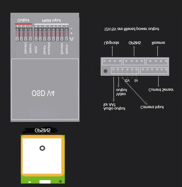
3 MAIN CONNECTION
4 INSTALLATION GUIDE CONFIGURATION A three-way switch is equipped, and each way corresponds to 1 display mode. If the channel for transfer switch is not connected, details-mode would be displayed by default. The current sensor and voltage detector are tuned before delivery, if there are relatively high deviations, please contact us for the tuning software. DISPLAY MODES There are 3 display modes: details-mode, simple-mode and alarm-mode. These 3 modes can be switched by a three-way switch on the remote control. Please refer to the Operation Procedures section for the specific switching methods. Here are the introductions for these 3 display modes: Details-mode Details-mode displays most of the indication information, including latitude, longitude, numbers of GPS satellites, speed, altitude, scrollbar, flying direction (shown by the plane icon), existing location & direction corresponding to the point of departure, returning angle & direction, horizontal distance corresponding to the point of departure, current, voltage, electricity consumption, remaining electricity, flying time and signal indication of remote control, which are shown in the following diagram. The rectangle in the center is the display range of the plane icon. As a warning, many of the displayed information would flash. When the GPS signal is not strong enough, latitude, longitude, numbers of GPS satellites, speed, altitude, the plane icon, returning angle & direction, horizontal distance corresponding to the point of departure would be flashing. When the signal becomes fine, flashing would stop automatically. When user enters this mode the first time after charging, if positioning of the GPS has not yet been completed, latitude and longitude would not be shown. The display area would appear the flashing words of GPS Searching Data, which means the GPS is still searching for the satellites. To guarantee the navigation information is accurate, please wait until the latitude and longitude data are displayed before takeoff. If the device is under interference, signal indication of remote control would flash for certain seconds, so as to warn the user that it is out of the control range. When there is a SD card, SD Card Indication would be displayed. If there is problem in data saving, this display information would flash. When it is under voltage because of not enough electricity (for example, the voltage of 3S battery is lower than 10.6V), the voltage and remaining electricity would be flashing to remind user to take appropriate actions, such as starting the return journey.
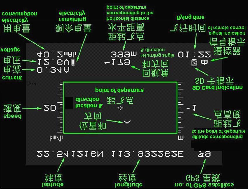
5

6 Simple-mode Simple-mode would only display the common and critical indication information, including speed, returning angle & direction, horizontal distance corresponding to the point of departure, voltage, electricity consumption and remaining electricity, which are shown in the following diagram. Same as Details-mode, when the GPS signal is not strong enough, speed, altitude, returning angle & direction, horizontal distance corresponding to the point of departure would be flashing. When the signal becomes fine, flashing would stop automatically. When it is under voltage because of not enough electricity (for example, the voltage of 3S battery is lower than 10.6V), the voltage and remaining electricity would be flashing to remind the user to take appropriate actions.

7 Alarm-mode The default Alarm-mode would not display any information, it would only display the corresponding warning information and flash. When the GPS signal is not strong enough, speed, altitude, returning angle & direction, horizontal distance corresponding to the point of departure would be displayed and flash. When the signal becomes fine, the information would disappear automatically. When it is under voltage because of not enough electricity (for example, the voltage of 3S battery is lower than 10.6V), the voltage and remaining electricity would be displayed and flash. The following diagram shows the Alarm-mode with under voltage warning.
8 DISPLAYED INFORMATION DESCRIPTION Description Display Range Latitude N is North Latitude, S is South Latitude, Unit is Degree 90.0N~0~90.0S Longitude E is East Longitude, W is West Longitude, Unit is Degree 180.0E~0~180.0W Numbers satellites of GPS Numbers of GPS satellite that can be received signal currently. 0~9; 9 would be displayed even more than 9 Speed Total speed, unit is Km/ hour 0~999km/h Current Operation current, unit is A 0.0~99.9A Voltage System voltage, unit is V. it would flash when under voltage. 0.0~99.9V Electricity consumption Remaining electricity Point of departure Location & direction Altitude corresponding to the point of departure Returning direction angle & Horizontal distance corresponding to the point of departure SD Card indication Signal indication of remote control Flying time The electricity consumed from system start-up till now, unit is mah The battery symbol indicates the remaining electricity level, when it is nearly used up, the symbol would flash. Indicate the point of departure The plane icon indicates the existing location & direction corresponding to the point of departure. Up: North, Down: South, Left: West, Right: East. The flying direction is shown by the plane icon. Altitude that corresponding to the point of departure. The figure can be negative, unit is meter. Indicate the required angle and direction for a returning journey, the unit for angle is degree. When angle is less than 5 degree, it would consider as accurate, so direction would not be displayed. The horizontal distance corresponding to the point of departure, the unit would be adjusted automatically. When there is a SD card, this information would be displayed. If there is problem in data saving, it would flash. When the device is under interference and out of control range, it would flash. The flying time is accumulated from the first take-off. When there are 4 or more GPS satellites and the speed exceeds 5m/s the first time, it starts counting. 0.0~9999mAH It takes a 2200mAH battery as indication standard ~9999m 0~99.9km

9 AUTOPILOT SECTION NSTALLATION FOR THE HARDWARE 1. Connection a. Install the sensor GPSINS horizontally. The cable connector should be placed toward the nose. b. According to the abovediagram, PWM Input connect with RC receiver Input 1 connect Aileron channel Input 2 connect Elevator channel Input 5 connect a 3-switch channel to switch autopilot mode Input 6 connect a 3-switch channel to switch display mode PWM output connect with servo Output 1 connect Aileron servo Output 2 connect Elevator servo Input(3/4/7) and Output(3/4) are reserve channel 2. Keep the remote control in normal mode 3.In order to ensure the safe, please check all connections again before OSD power on. 4.After OSD power on, the following menu would be shown::


10 System would detect the equipments that connected to the OSD control board automatically, then the software & hardware version would be displayed. Meanings of the information shown above: HW4.0 & SW1.0.0: represents hardware and software version are 4.0 and 1.0 respectively. Logger: represents if the data logger is detected by the system. It flashes if the data logger is not detected. GPS/INS /INS: represents if the GPS/INS is detected by the system. It flashes if GPS/INS is not detected. RC CH IN: is the RC receiver input channel About 10 seconds after power connection, the system will enter one of the three modes. (It depends on the switch status of the remote control.) If the displayed information is different from the equipments connected, please check again before take-off. SOFTWARE SETTING A After OSD initialization iscomplete, the following menu would be shown:


11 Select among the above items with the help of Autopilot channel switch, enter the corresponding menu with the Switch channel switch. Meaning of the menu: Fly ly: Enter the flying mode. If no action is taken, it would enter the flying mode automatically after a while. OSD: the OSD-related configuration page, including units, warnings, RSSI calibration etc. Enter the OSD page when setting is needed. Autopilot utopilot: the Autopilot-related configuration page. B..Enter Autopilot menu. Autopilot includes 5 sub-menu Servos_Calibrate:Calibration input signal menu Install_Relate:Installation setting menu Control_PID:set the autopilot-related sensitivity Control_MISC:miscellaneous setting, including the setting of maximum turning angle and safety altitude etc. Control_Safety:Safety parameters C:Enter Install_Relatemenu to select airplane type; Tradition: is fixed wing, One port correspond one servo Fly wing: is flying wing mode,1,2 channel will mix output. D:Connect Aileron and Elevator servo Check the wing control output in manual mode E. Servo_Calibrate Menu
 is acceptable) would be shown when joystick is put in the center position.")
12 The interface would display the real-time steering gear input values, with the range of -100 to After calibration, near 0 (< (+-5) is acceptable) would be shown when joystick is put in the center position. Calibrate the aileron aileron channel: Select the item of Aile with the help of Autopilot channel switch, enter the menu with the Switch channel switch. At this moment, the figures after Aile would be flashing, which means it is under calibration. First, keep the joystick in the center position for about 5 seconds. And then, put the aileron joystick to the end of the right-hand side for about 5 seconds. After that, return to the center position and slide the Switch channel switch once. The figures would stop flashing, which means calibration is completed. After calibration, near 0 would be shown when joystick is put in the center position, near 100 would be shown when joystick is at the end of the right-hand side. Calibrate the Pitch Pitch channel: Select the item of Elev with the help of Autopilot channel switch, enter the menu with the Switch channel switch. At this moment, the figures after Elev would be flashing, which means it is under calibration. First, keep the joystick in the center position for about 5 seconds. And then, put the pitch joystick to the lowest position for about 5 seconds. After that, return to the center position and slide the Switch channel switch once. The figures would stop flashing, which means calibration is completed. After calibration, near 0 would be shown when joystick is put in the center position, near 1000 would be shown when joystick is at the lowest position. This calibration would calibrate the steering gear direction and travel as well, and it must be done according to the above procedures. And then, user needs to check if the direction is correct after calibration. For aileron channel, near 0 (< (+-5) is acceptable) would be shown when joystick is put in the center position, near 100 would be shown when joystick is at the end of the right-hand side. For Pitch channel, near 0 (< (+-5) is acceptable) would be shown when joystick is put in the center position, near 100 would be shown when joystick is at the lowest position. If the steering and displayed direction are inconsistent, then there would be an opposite control direction. And the aircraft will turn over after entering the Balanced Mode. There is no need to calibrate the throttle and direction channels at this moment. Note: this operation must be done after the aircraft has completed the Manual Mode calibration. If the steering gear has relatively large travel adjustment or mechanical calibration is undertaken, calibration must be done once again. Exit this menu. F. Control_PID Menu


13 Stability:Stabilization parameters Roll_Aile:set the sensitivity for the aileron. If the aircraft vibrates in Balanced Mode, then user should tune down the corresponding value. If user cannot get sufficient control for the aircraft, tune up the value.. Pitch_Elev:set the elevator sensitivity, adjustment principle is same as above. Yaw_Roll:set the sensitivity for the yaw. If the aircraft vibrates in Balanced Mode, then user should tune down the corresponding value. If user cannot get sufficient control for the aircraft, tune up the value.. Alt_Pitch:set the height sensitivity, adjustment principle is same as above.. G:Control_MISC setting menu MaxRoll: Set the maximum rolling angle. If the turning angle is too small, then user should tune up the value. Semi-Automatic Mode: This value represents the maximum value that joystick can achieve. When joystick is put in the center position, that means the turning angle is 0. When joystick is put at the end of the right-hand side (reach the maximum value of 1000), that means controlling the aircraft to the MaxRoll angle. For the value in between, the aircraft would turn on proportion. Autopilot Mode: This value represents the maximum turning angle. By default, 1 degree of

14 turning deviation would be corrected by 1 degree of rolling angle. MaxPitch: Set the maximum pitching angle. If the climbing ability is not enough, then user should tune up the value. Semi-Automatic Mode: This value represents the maximum value that joystick can achieve. When joystick is put in the center position, that means the pitching angle is 0. When joystick is put at the lowest position (reach the maximum value of 1000), that means the aircraft would climb in the MaxPitch angle. For the value in between, the aircraft would climb on proportion. Autopilot Mode: By default, when there is 10 meters of height deviation, the aircraft would climb or descent in this pitching angle. Not to stall the aircraft, the value should not be too large. H:Control_Safety SecureAlt: Set the safe Altitude. The setting is mainly used in the return flight. If the flying altitude of the return flight is lower than this value, the aircraft would climb to the safe altitude. If the flying altitude is higher than this value, the aircraft would keep flying with that altitude. I:Attitude indicator. R:means Roll, Right roll is positive, left roll is negative P:means Pitch, Nose-up is positive, otherwise it is negative

15 FIELD TEST A: Set the aircraft in Manual Mode B: Adjust the travel and direction for the steering gear C: Check the actual tilting angle is consistent with the displayed value in open area. D: Enter Attitude Control Mode, check if the feedback direction is correct. If not, enter PWM menu to confirm the joystick and display direction are consistent. If they are inconsistent, execute the calibration again E: Start flying under Manual Mode, observe the aircraft attitude is consistent with that shown in infrared display. F: When the aircraft flies above 50 meters, switch to the Attitude Control Mode and check the control situation. [It is not suggested to use the infrared balancer under 50 meters because of the earth s surface interference.] If the aircraft vibrates, then user should tune down the corresponding value. Otherwise, user can tune up the value and let OSD to have sufficient control in attitude balancing. G: In Attitude Control Mode, put the Aileron joystick to the end of the right-hand side to check the maximum rolling ability. If the rolling angle is too small, then user should tune up the MaxRoll value, and vice versa. H. In Attitude Control Mode, put the Elevator joystick to the maximum value and check the maximum climbing & descending abilities. If the abilities are too weak, then user should tune up the MaxPitch value, and vice versa. I: Switch to Return Flight Mode from a short distance, observe the aircraft performances. Check if it can control the flying attitude and hover for at least 5 laps. J: If all above operations are under normal conditions, user can move on to the long distance return flight. K: If aircraft returns under normal conditions, user can set the waypoints and start flying. Note
16 The three-way switch of Autopilot represents: is displayed on OSD, which is the Manual Mode is displayed on OSD, which is the Attitude Control Mode is displayed on OSD, which is the Return Flight Mode is displayed on OSD, which is the Waypoints Mode If there are 4 or more GPS satellites and the take-off position has not been locked, user will find the flashing icon in Return Flight Mode. If the GPS is not connected or there are less than 4 satellites, user will find the flashing icon. That means it is not allowed to enter the Return Flight Mode. All the parameters would be overwritten after software upgrade, thus calibration must be executed once again. In Flying Mode, user can quit the OSD Details-mode (by sliding the Switch channel switch 3 times) and enter the Configuration Mode for adjustment. The Configuration Mode can be entered only within 30 meters from the take-off point.
Skylark Trace IV User Manual
 Skylark Trace IV User Manual A skylark soars above the clouds. 一只云雀在云上翱翔 WWW.SkylarkFPV.com SATETY WARNING SKYLARK OSD is for entertainment purpose only, users should bear all the risks involved when using
A3 Pro INSTRUCTION MANUAL. Oct 25, 2017 Revision IMPORTANT NOTES
 A3 Pro INSTRUCTION MANUAL Oct 25, 2017 Revision IMPORTANT NOTES 1. Radio controlled (R/C) models are not toys! The propellers rotate at high speed and pose potential risk. They may cause severe injury
Arkbird Hummingbird BNF Version Airplane User Manual Caution
 Arkbird Hummingbird BNF Version Airplane User Manual Caution 1) Please abide by relevant laws: No flying in populated area, no flying in airport clearance area (10km away from both sides of the runway,
New functions and changes summary
 New functions and changes summary A comparison of PitLab & Zbig FPV System versions 2.50 and 2.40 Table of Contents New features...2 OSD and autopilot...2 Navigation modes...2 Routes...2 Takeoff...2 Automatic
ARKBIRD-Tiny Product Features:
 ARKBIRD-Tiny Product Features: ARKBIRD System is a high-accuracy autopilot designed for fixed-wing, which has capability of auto-balancing to ease the manipulation while flying. 1. Function all in one
FY-41AP Autopilot & OSD System Installation & Operation Manual
 FY-41AP Autopilot & OSD System Installation & Operation Manual Multi-rotor Version V2.22 And Above Guilin Feiyu Technology Incorporated Company Addr : 3rd Floor,B,Guilin Electric Valley,Innovation Building,
Arkbird OSD 2.0 Includes:
 ARKBIRD is a high-accuracy autopilot designed for fixed-wing. It can superimpose OSD (On Screen Display) data on videos and at the same time control the balance, the return and many other maneuvers of
FY-41AP Autopilot & OSD System
 FY-41AP Autopilot & OSD System Installation & Operation Manual (Multi-rotor Version) Guilin Feiyu Electronic Technology Co., Ltd Address: 4 th Floor,YuTaiJie Science Technology Building, Information Industry
Autopilot System Installation & Operation Guide. Guilin Feiyu Electronic Technology Co., Ltd
 2011-11-26 FEIYU TECH FY31AP Autopilot System Installation & Operation Guide Guilin Feiyu Electronic Technology Co., Ltd Rm. C407, Innovation Building, Information Industry Park, Chaoyang Road, Qixing
Introduction. Overview. Outputs Normal model 4 Delta wing (Elevon) & Flying wing & V-tail 4. Rx states
 & Flying wing & V-tail 4. Rx states") Introduction Thank you for purchasing FrSky S6R/S8R (SxR instead in this manual) multi-function telemetry receiver. Equipped with build-in 3-axis gyroscope and accelerometer, SxR supports various functions.
Introduction Thank you for purchasing FrSky S6R/S8R (SxR instead in this manual) multi-function telemetry receiver. Equipped with build-in 3-axis gyroscope and accelerometer, SxR supports various functions.
Flight control Set and Kit
 Flight control Set and Kit Quick Start Guide For MegaPirate NG Version 1.2 Thanks for choosing AirStudio flight control electronics. We have created it based on best-in-class software, hardware and our
Long Range Wireless OSD 5.8G FPV Transmitter
 Long Range Wireless OSD 5.8G FPV Transmitter Built-in 10 Axis AHRS + MAVLINK + 600mW Support all flight controller and GPS 1 / 14 User's Guide Catalogue Product Instruction 3 Features 3 Specifications.4
A3 SUPER 3 INSTRUCTION MANUAL. For Firmware Version 1.0, Data Version 1.0 Oct 25, 2017 Revision.
 A3 SUPER 3 INSTRUCTION MANUAL For Firmware Version 1.0, Data Version 1.0 Oct 25, 2017 Revision support@hobbyeagle.com 1 CONTENTS IMPORTANT NOTES.....3 1. Introduction......4 2. Setup Procedure Overview...5
Guilin Feiyu Electronic Technology Co., Ltd. Guilin FeiYu Electronic Technology Co.
 Hornet-OSD Manual Feiyu Tech Guilin FeiYu Electronic Technology Co., Ltd Addr:Room C407, Innovation Building, Information Industry Park, ChaoYang Road, QiXing District, Guilin China Web:http://www.feiyudz.cn
FOXTECH Nimbus VTOL. User Manual V1.1
 FOXTECH Nimbus VTOL User Manual V1.1 2018.01 Contents Specifications Basic Theory Introduction Setup and Calibration Assembly Control Surface Calibration Compass and Airspeed Calibration Test Flight Autopilot
UP30 UAV Autopilot System Manual Version 5.7
 UP30 UAV Autopilot System Manual Version 5.7-0 - CONTENTS Warning, warranty and upgrade.....3 Warning....... 3 Warranty...... 3 Upgrade....... 3 Contact..... 4 Introduction to UP30 Autopilot System....
Detrum MSR66A Receiver
 Motion RC User Guide for the Detrum MSR66A Receiver Version 1.0 Contents Review the Receiver s Features... 1 Review the Receiver s Ports and Connection Orientation... 2 Bind the Receiver to a Transmitter
FY-DOS Manual For Multi-rotors Control
 FY-DOS Manual For Multi-rotors Control Installation & Operation Multi-rotor firmware above V2.20 Dear Customer: Thank you for choosing DOS as your autopilot system. Please read this manual carefully before
Pitlab & Zbig FPV System Version 2.60a. Pitlab&Zbig OSD. New functions and changes in v2.60. New functions and changes since version 2.
 Pitlab & Zbig FPV System Version 2.60a since version 2.50a Pitlab&Zbig OSD in v2.60a Added support for new Pitlab airspeed sensor. Sensor is connected to yellow OSD socket and is configured in similar
Product Introduction:
 Product Introduction: ARKBIRD-433UHF is a 10-channel module designed for long-distance flight: 1. The advanced code division frequency hopping system (FHSS) produces the only way of frequency hopping sequence
FY-DOS Manual For Multi-rotors Control
 FY-DOS Manual For Multi-rotors Control Installation & Operation Multi-rotor firmware above V2.10 Dear Customer: Thank you for choosing DOS as your autopilot system. Please read this manual carefully before
User Manual Version 1.0
 1 Thank you for purchasing our products. The A3 Pro SE controller is the updated version of A3 Pro. After a fully improvement and optimization of hardware and software, we make it lighter, smaller and
Revision For Firmware Version V3.30 or above & Adjusting-parameter software Version V1.40 or above
 T1 User Manual V1.4 2016.07.20 Revision For Firmware Version V3.30 or above & Adjusting-parameter software Version V1.40 or above Please strictly follow these steps to mount and use this product, as well
BREEZE OSD pro V1.1 manual
 BREEZE OSD pro V1.1 manual Thanks for purchasing Cyclops OSD products. Connection diagram Important: select Jumper instructions: 1, 2 short circuit for using power batteries(which must be 12V, or 3S Lipo
YS-S4 Multi-rotor Autopilot User Manual V1.4
 User Manual V1.4 YS-S4 Multi-rotor Autopilot Zero UAV (Beijing) Intelligence Technology Co. Ltd 1 1. In-Box...3 2. Functions... 4 3. Installation... 5 4. Connections...6 4.1 Assembly... 6 4.2 Real connection
FY-41AP Lite AutoPilot & OSD System. Installation & Operation Manual
 FY-41AP Lite AutoPilot & OSD System Installation & Operation Manual Guilin Feiyu Electronic Technology Co., Ltd Addr : 4 th Floor,YuTaiJie Science Technology Building,Information Industry Park, ChaoYang
EzOSD Manual. Overview & Operating Instructions Preliminary. April ImmersionRC EzOSD Manual 1
 EzOSD Manual Overview & Operating Instructions Preliminary. April 2009 ImmersionRC EzOSD Manual 1 Contents Overview... 3 Features... 3 Installation... 3 1. Installation using an ImmersionRC camera and
INSTRUCTIONS. 3DR Plane CONTENTS. Thank you for purchasing a 3DR Plane!
 DR Plane INSTRUCTIONS Thank you for purchasing a DR Plane! CONTENTS 1 1 Fuselage Right wing Left wing Horizontal stabilizer Vertical stabilizer Carbon fiber bar 1 1 1 7 8 10 11 1 Audio/video (AV) cable
FY-DoS for multi-rotors control manual
 FY-DoS for multi-rotors control manual Feiyu Tech Installation & Operation Multi-rotor firmware above V2.10 Dear Customer: Thank you for choosing DoS as your autopilot system. Please read this manual carefully
Classical Control Based Autopilot Design Using PC/104
 Classical Control Based Autopilot Design Using PC/104 Mohammed A. Elsadig, Alneelain University, Dr. Mohammed A. Hussien, Alneelain University. Abstract Many recent papers have been written in unmanned
Multi-rotor flight stabilization & Autopilot System Installation & Operation Guide. Guilin Feiyu Electronic Technology Co., Ltd
 Rev: 5 th July 2011 FEIYU TECH FY-91Q DREAMCATCHER Multi-rotor flight stabilization & Autopilot System Installation & Operation Guide Guilin Feiyu Electronic Technology Co., Ltd Rm. B305, Innovation Building,
Heterogeneous Control of Small Size Unmanned Aerial Vehicles
 Magyar Kutatók 10. Nemzetközi Szimpóziuma 10 th International Symposium of Hungarian Researchers on Computational Intelligence and Informatics Heterogeneous Control of Small Size Unmanned Aerial Vehicles
Atlas-450 FPV Brushless FPV
 Atlas-450 FPV Brushless FPV Atlas-450 is a kind of micro brushless FPV delta-wing airplane base on the design idea of reliability, safety and concise, her flight time is as long as 20 minutes! Park flying
Post-Installation Checkout All GRT EFIS Models
 GRT Autopilot Post-Installation Checkout All GRT EFIS Models April 2011 Grand Rapids Technologies, Inc. 3133 Madison Avenue SE Wyoming MI 49548 616-245-7700 www.grtavionics.com Intentionally Left Blank
Detrum GAVIN-8C Transmitter
 Motion RC Supplemental Guide for the Detrum GAVIN-8C Transmitter Version 1.0 Contents Review the Transmitter s Controls... 1 Review the Home Screen... 2 Power the Transmitter... 3 Calibrate the Transmitter...
OughtToPilot. Project Report of Submission PC128 to 2008 Propeller Design Contest. Jason Edelberg
 OughtToPilot Project Report of Submission PC128 to 2008 Propeller Design Contest Jason Edelberg Table of Contents Project Number.. 3 Project Description.. 4 Schematic 5 Source Code. Attached Separately
FY-91Q DREAMCATCHER TECH. Multi-rotor flight stabilization & Autopilot System Installation & Operation Guide
 Rev 6: 7 th July 2011 FEIYU TECH FY-91Q DREAMCATCHER Multi-rotor flight stabilization & Autopilot System Installation & Operation Guide Guilin Feiyu Electronic Technology Co., Ltd Rm. B305, Innovation
Introduction Thank you for your purchase! This instruction manual will guide you through the installation and operation of your OSD Pro.
 Instruction Manual for OSD Pro Document Version 4.9 Corresponds to Eagle Tree Software Version 10.44 or higher Introduction Thank you for your purchase! This instruction manual will guide you through the
Height Limited Switch
 Height Limited Switch Manual version: 1.0 Content Introduction...3 How it works...3 Key features...3 Hardware...4 Motor cut-off settings...4 Specification...4 Using the RC HLS #1 module...5 Powering the
Fokker 50 - Automatic Flight Control System
 GENERAL The Automatic Flight Control System (AFCS) controls the aircraft around the pitch, roll, and yaw axes. The system consists of: Two Flight Directors (FD). Autopilot (AP). Flight Augmentation System
X4V2 Flight Controller Manual V1.1
 X4V2 Flight Controller Manual V1.1 Zero UAV (Beijing) Intelligence Technology Co., Ltd. Table of Contents 1 Warning and Disclaimer... 1 2 Terms and Abbreviations... 3 3 Functions... 4 4 In the Box... 5
Caution Notes. Features. Specifications. Installation. A3-L 3-axis Gyro User Manual V1.0
 Caution Notes Thank you for choosing our products. If any difficulties are encountered while setting up or operating it, please consult this manual first. For further help, please don t hesitate to contact
Pro Pilot Operation and Installation Manual Trio Avionics Corporation
 Pro Pilot Operation and Installation Manual Trio Avionics Corporation Version 3.8 Notice: This manual uses illustrations that generally show the Pro Pilot model that mounts in a standard 3-1/8 round cutout
U-Pilot can fly the aircraft using waypoint navigation, even when the GPS signal has been lost by using dead-reckoning navigation. Can also orbit arou
 We offer a complete solution for a user that need to put a payload in a advanced position at low cost completely designed by the Spanish company Airelectronics. Using a standard computer, the user can
A3-AG/N3-AG. Agriculture Kit. User Manual V
 A3-AG/N3-AG Agriculture Kit User Manual V2.0 2017.08 Contents A3-AG Introduction 3 N3-AG Introduction 6 Agriculture Management Unit (AMU) Introduction 9 Installation 10 Overview 10 Start the Installation
August/5/2010 FY-20A FLIGHT STABILIZATION SYSTEM TECH INSTALLATION & OPERATION MANUAL
 August/5/2010 FEIYU TECH FY-20A FLIGHT STABILIZATION SYSTEM INSTALLATION & OPERATION MANUAL Dear Pilot, Thank you for purchasing the FY-20A stabilizer from FeiYu Tech. In order to achieve full potential
Thank you for purchasing this DJI product. Please strictly follow these steps to mount and connect this system on
 NAZA-M LITE User Manual V 1.00 2013.05.28 Revision For Firmware Version V1.00 & Assistant Software Version V1.00 Thank you for purchasing this DJI product. Please strictly follow these steps to mount and
Google Earth Tutorials
 Google Earth Tutorials Tutorial 1 Beginner Videos 1: Street View Now you can fly from outer space down to the streets with Street View. Seamlessly integrated with Google Earth, Street View lets you experience
Quick Start Guide V1.1
 X-Pilot autopilot for bait boats Quick Start Guide V1.1 www.toslon.com 1. What s on the display & Keypad instruction 6 7 8 9 10 13 14 15 16 5 4 12.1V 10 1.1 m/s 2 86.5m 10 4 deg 11 275.2m 1.2m/s 18 deg
Electrical connection
 Electrical connection Autopilot works exclusively in combination with the OSD. All electrical connections between the OSD and autopilot PCBs are made through a dedicated connector on both PCBs. When purchasing
Flight Detector Indicator
 Flight Detector Indicator Part No: 777-1224-003 Components Maintenance Manual No: 34-25-12 By Soumyadeep Das Raj shekhar Chatterjee Purpose of equipment: The flight detector indicator (FDI) is a part of
Pro Pilot Operation Manual Trio Avionics Corporation
 Pro Pilot Operation Manual Trio Avionics Corporation Manual Part Number 13200000 Notice: This manual uses illustrations that generally show the Pro Pilot model that mounts in a standard 3-1/8 round cutout
User Guide. Advanced Ground Control Station Unit & Antenna Tracker RVGS. RangeVideo RVGS Control Station Manual 1
 Advanced Ground Control Station Unit & Antenna Tracker RVGS RangeVideo RVGS Control Station Manual 1 Your Guide To the Ground Station Control and Antenna Tracker Unit Table of Contents 1. Introducing RVGS
One connected to the trainer port, MagTrack should be configured, please see Configuration section on this manual.
 MagTrack R Head Tracking System Instruction Manual ABSTRACT MagTrack R is a magnetic Head Track system intended to be used for FPV flight. The system measures the components of the magnetic earth field
Operating Handbook. For. Gemini Autopilot
 Operating Handbook For Gemini Autopilot TRUTRAK FLIGHT SYSTEMS 1488 S. Old Missouri Road Springdale, AR 72764 Ph. 479-751-0250 Fax 479-751-3397 www.trutrakap.com Table of Contents 1. Revisions... 5 2.
NAZA-M Quick Start Guide V 1.0
 NAZA-M Quick Start Guide V 1.0 Thank you for purchasing this DJI product. Please regularly visit the NAZA-M web page at www.dji-innovations.com. This page is updated regularly. Any technical updates and
Recent Progress in the Development of On-Board Electronics for Micro Air Vehicles
 Recent Progress in the Development of On-Board Electronics for Micro Air Vehicles Jason Plew Jason Grzywna M. C. Nechyba Jason@mil.ufl.edu number9@mil.ufl.edu Nechyba@mil.ufl.edu Machine Intelligence Lab
17 Wellington Business Park Crowthorne Berkshire RG45 6LS England. Tel: +44 (0)
") 17 Wellington Business Park Crowthorne Berkshire RG45 6LS England Tel: +44 (0) 1344 234047 www.flightdatapeople.com Information Sheet www.flightdatapeople.com Commercial in Confidence Hosted Flight Data
17 Wellington Business Park Crowthorne Berkshire RG45 6LS England Tel: +44 (0) 1344 234047 www.flightdatapeople.com Information Sheet www.flightdatapeople.com Commercial in Confidence Hosted Flight Data
FAA APPROVED AIRPLANE FLIGHT MANUAL SUPPLEMENT FOR. Trio Pro Pilot Autopilot
 Page 1 480 Ruddiman Drive TRIO AP Flight Manual Supplement North Muskegon, MI 49445 L-1006-01 Rev D FOR Trio Pro Pilot Autopilot ON Cessna 172, 175, 177, 180, 182, 185 and Piper PA28 Aircraft Document
RC Altimeter #2 BASIC Altitude data recording and monitoring system 3/8/2009 Page 2 of 11
 Introduction... 3 How it works... 3 Key features... 3 System requirements... 3 Hardware... 4 Specifications... 4 Using the RC Altimeter #2 BASIC module... 5 Powering the module... 5 Mounting the module...
Digiflight II SERIES AUTOPILOTS
 Operating Handbook For Digiflight II SERIES AUTOPILOTS TRUTRAK FLIGHT SYSTEMS 1500 S. Old Missouri Road Springdale, AR 72764 Ph. 479-751-0250 Fax 479-751-3397 Toll Free: 866-TRUTRAK 866-(878-8725) www.trutrakap.com
The brain for the plane is the Airelectronics' U-Pilot flight control system, which is embedded inside the plane's fuselage, leaving a lot of space on
 Airelectronics has developed a new complete solution meeting the needs of the farming science. The completely test Skywalkerplatform has been equipped with both thermal and multispectral cameras to measure
Mapping with the Phantom 4 Advanced & Pix4Dcapture Jerry Davis, Institute for Geographic Information Science, San Francisco State University
 Mapping with the Phantom 4 Advanced & Pix4Dcapture Jerry Davis, Institute for Geographic Information Science, San Francisco State University The DJI Phantom 4 is a popular, easy to fly UAS that integrates
Installation & Operation Manual
 PandaⅡAutopilot System Installation & Operation Manual Apply To The Firmware V1.35 And Above Version Guilin Feiyu Electronic Technology Co., Ltd Addr : 4 th Floor,YuTaiJie Science Technology Building,Information
Digiflight II SERIES AUTOPILOTS
 Operating Handbook For Digiflight II SERIES AUTOPILOTS TRUTRAK FLIGHT SYSTEMS 1500 S. Old Missouri Road Springdale, AR 72764 Ph. 479-751-0250 Fax 479-751-3397 Toll Free: 866-TRUTRAK 866-(878-8725) www.trutrakap.com
Operating Handbook For FD PILOT SERIES AUTOPILOTS
 Operating Handbook For FD PILOT SERIES AUTOPILOTS TRUTRAK FLIGHT SYSTEMS 1500 S. Old Missouri Road Springdale, AR 72764 Ph. 479-751-0250 Fax 479-751-3397 Toll Free: 866-TRUTRAK 866-(878-8725) www.trutrakap.com
EXMITTER -- Professional Remote Control Products Expert
 EXMITTER -- Professional Remote Control Products Expert WARNING The following terms are used throughout the product literature to indicate various levels of potential harm when operating this product.
A2 Flight Control System
 A2 Flight Control System User Manual V1.26 April, 2017 Revision Thank you for purchasing DJI products. Please strictly follow these steps to mount and connect this system on your aircraft, install the
Operating Handbook. For. Gemini Autopilot
 Operating Handbook For Gemini Autopilot TRUTRAK FLIGHT SYSTEMS 1488 S. Old Missouri Road Springdale, AR 72764 Ph. 479-751-0250 Fax 479-751-3397 www.trutrakap.com Table of Contents 1. Revisions... 5 2.
MyFlyDream AutoPilot
 MyFlyDream AutoPilot V1.16 beta www.myflydream.com Please read chapter 10 (Important Safety Notes and Disclaimers) prior to attempting flights with MFD autopilot Notes Thank you for purchasing the MyFlyDream
Dash8-200/300 - Automatic Flight AUTOMATIC FLIGHT CONTROLS AND INDICATORS. Page 1
 AUTOMATIC FLIGHT CONTROLS AND INDICATORS FLIGHT GUIDANCE MODE SELECTORS (alternate action) - Engages flight director modes of operation. - Flight director command bars display lateral and/or vertical guidance
Black Knight. Black Knight 210/250 FPV Quadcopter Manual
 Black Knight Black Knight 210/250 FPV Quadcopter Manual Version: Naze V6 V1.1 www.spedix-rc.com WARNING For age 14+ only. Rotating propellers may cause serious injury and damages! Do not install propellers
MGL Avionics. iefis. Integrated Autopilot. User and installation manual. Manual dated 14 November Page 1
 MGL Avionics iefis Integrated Autopilot User and installation manual Manual dated 14 November 2014 Page 1 Table of Contents General...4 Autopilot abilities...4 External autopilot systems...4 Internal autopilot
Frequently Asked Questions
 HORIZON mp Questions Frequently Asked Questions 2004-2006 MicroPilot, 72067 Road 8E, Sturgeon Rd., 1 Stony Mountain MB R0C 3AO Canada Edited: February 4, 2014 MicroPilot 72067 Road 8E, Sturgeon Rd., Stony
DragonLink Advanced Transmitter
 DragonLink Advanced Transmitter A quick introduction - to a new a world of possibilities October 29, 2015 Written by Dennis Frie Contents 1 Disclaimer and notes for early release 3 2 Introduction 4 3 The
DAM Quick Start. Digital Aircraft Modeler Tutorial. Example Files
 Digital Aircraft Modeler Tutorial DAM Quick Start DAM is far more than just a flight simulator. DAM is designed and written from the ground up to give you complete control in creating your own models and
Fixed Wing Models 55
 Fixed Wing Models 55 Two Snap-Roll programs Automatic switching of control characteristics (access via Set-Up Menu) (access via Set-Up Menu) 56 Fixed Wing Models AUTOMATIC MANOEUVRE The switches to operate
Tiny Flight Tracker & Viewer Manual
 Tiny Flight Tracker & Viewer Manual Version 3.xx Note: Program version number that appears in the pictures of this document may not reflect the latest available release. Tiny Flight Tracker & Viewer v3.xx
EXMITTER -- Professional Remote Control Products Expert
 EXMITTER -- Professional Remote Control Products Expert WARNING The following terms are used throughout the product literature to indicate various levels of potential harm when operating this product.
Dedalus autopilot user's manual. Dedalus autopilot. User's manual. Introduction
 Introduction Dedalus autopilot Thank you for purchasing Dedalus Autopilot. We have put our many year experience in electronics, automatics and control of model planes into this device. User's manual Dedalus
T18MZ SOFTWARE UPDATE CHANGES
 T18MZ SOFTWARE UPDATE CHANGES (Editor Version: 2.5 Encoder version: 2.2) This software updates or alters the functions and features noted below. The instructions and information that follow are meant as
T18MZ SOFTWARE UPDATE CHANGES
 T18MZ SOFTWARE UPDATE CHANGES (Editor Version: 2.7 Encoder version: 2.3) This software updates or alters the functions and features noted below. The instructions and information that follow are meant as
Storm Racing Drone SRD370. with DJI Naza Lite or DJI Naza V2 USER MANUAL. HeliPal.com. All Rights Reserved
 Storm Racing Drone SRD370 with DJI Naza Lite or DJI Naza V2 USER MANUAL V6! 1 DISCLAIMER Please read this disclaimer carefully before using this product. This product is a hobby with motors but not a toy
VCU Skyline. Team Members: Project Advisor: Dr. Robert Klenke. Last Modified May 13, 2004 VCU SKYLINE 1
 VCU Skyline Last Modified May 13, 2004 Team Members: Abhishek Handa Kevin Van Brittiany Wynne Jeffrey E. Quiñones Project Advisor: Dr. Robert Klenke VCU SKYLINE 1 * Table of Contents I. Abstract... 3 II.
Table of Contents. Introduction 3. Pictorials of the 40 and 50 Systems 4. List of Applicable Acronyms 6
 Table of Contents Introduction 3 Pictorials of the 40 and 50 Systems 4 List of Applicable Acronyms 6 System 40 Modes of Operation 7 System 40 Functional Preflight Procedures 10 System 40 In Flight Procedures
T18MZ SOFTWARE UPDATE CHANGES
 T18MZ SOFTWARE UPDATE CHANGES (Editor Version: 2.6 Encoder version: 2.3) This software updates or alters the functions and features noted below. The instructions and information that follow are meant as
BGRI Stem Rust Survey Protocol. Overview of Field Survey Procedure
 Overview of Field Survey Procedure 1. Ensure survey team have all items on check-list before departure 2. Travel to 1 st survey location 3. At survey location switch on GPS 4. Wait until GPS receives satellite
Here are some of the many choices you will be faced with: Brand (Futaba, Spektrum, JR, Hitec, etc.)
") 27 January 2015 Welcome - Bienvenue With so many RC radio systems on the market, and so many features How do you know what radio system is right for you? Choosing your best RC radio requires information
27 January 2015 Welcome - Bienvenue With so many RC radio systems on the market, and so many features How do you know what radio system is right for you? Choosing your best RC radio requires information
GPS System Design and Control Modeling. Chua Shyan Jin, Ronald. Assoc. Prof Gerard Leng. Aeronautical Engineering Group, NUS
 GPS System Design and Control Modeling Chua Shyan Jin, Ronald Assoc. Prof Gerard Leng Aeronautical Engineering Group, NUS Abstract A GPS system for the autonomous navigation and surveillance of an airship
EVO4 Data Logger USER GUIDE
 EVO4 Data Logger USER GUIDE AiM Srl. Via Cavalcanti, 8 20063 Cernusco S/N (MI) Italia Tel. (+39) 02.9290571 Made in Italy www.aim-sportline.com EVO4 Data Logger 04 INTRODUCTION 08 GETTING STARTED 12 GENERAL
DJI GO 4 Manual: The Pilot s Handbook
 DJI GO 4 Manual: The Pilot s Handbook DJI GO 4 Manual Contents February 5, 2018: 1 Introduction and Camera View 2 DJI GO 4 General Settings 3 Main Controller Settings 4 Visual Navigation Settings 5 Remote
Buddy Flight in the Pitlab FPV System
 Buddy Flight in the Pitlab FPV System The FPV flights are become increasingly popular in the world and more and more peoples spend it's free time in this way. Very often the FPV pilots is flying together
Study of M.A.R.S. (Multifunctional Aero-drone for Remote Surveillance)
") Study of M.A.R.S. (Multifunctional Aero-drone for Remote Surveillance) Supriya Bhuran 1, Rohit V. Agrawal 2, Kiran D. Bombe 2, Somiran T. Karmakar 2, Ninad V. Bapat 2 1 Assistant Professor, Dept. Instrumentation,
Study of M.A.R.S. (Multifunctional Aero-drone for Remote Surveillance) Supriya Bhuran 1, Rohit V. Agrawal 2, Kiran D. Bombe 2, Somiran T. Karmakar 2, Ninad V. Bapat 2 1 Assistant Professor, Dept. Instrumentation,
Short Instruction Manual. pp-rc Modellbau Weidenstieg Kölln-Reisiek Deutschland
 Short Instruction Manual 22.03.2010 Distribution: pp-rc Modellbau Weidenstieg 2 25337 Kölln-Reisiek Deutschland Tel.: +49 (0) 4121 740486 Fax: +49 (0) 4121 750676 www-pp-rc.de WEEE-Reg.-Nr DE77074747 Dear
INSTRUCTION MANUAL Version 1.0
 INSTRUCTION MANUAL Version 1.0 Camera Geotagger For Nikon or Canon GPS plus Beidou Barometric altimeter Position Tracing Logger Shutter Release Remoter LCD display Bluetooth technology GPS Contents Introduction
Basic GPS Operation. by Greg Whiley. Another practical publication from Aussie Star Flight Simulation
 Basic GPS Operation by Greg Whiley Another practical publication from Aussie Star Flight Simulation INTENTIONALLY LEFT BLANK Aussie Star Flight Simulation 2 Basic GPS Operations Statement of copyright
QUICK START GUIDE. AStrO. Ver Toll Free : 1 (877) Visit :
 Visit :") QUICK START GUIDE AStrO Ver.10.309 Toll Free : 1 (877) 462-7296 Visit : 1 Thank you for purchasing the latest in data acquisition technology, the AStrO. We hope that it surpasses your expectations. This
QUICK START GUIDE AStrO Ver.10.309 Toll Free : 1 (877) 462-7296 Visit : 1 Thank you for purchasing the latest in data acquisition technology, the AStrO. We hope that it surpasses your expectations. This
Storm Racing Drone SRD130S
 Storm Racing Drone SRD130S with BetaFlight Controller USER MANUAL V1.0 1 Copyright@2016 HeliPal.com. All Rights Reserved DISCLAIMER Please read this disclaimer carefully before using this product. This
A2 Flight Control System
 A2 Flight Control System User Manual V1.18 June 24th, 2014 Revision For Firmware 2.2 & Assistant Software V1.3 & DJI Assistant App V1.1.14 Thank you for purchasing DJI products. Please strictly follow
Neural Flight Control Autopilot System. Qiuxia Liang Supervisor: dr. drs. Leon. J. M. Rothkrantz ir. Patrick. A. M. Ehlert
 Neural Flight Control Autopilot System Qiuxia Liang Supervisor: dr. drs. Leon. J. M. Rothkrantz ir. Patrick. A. M. Ehlert Introduction System Design Implementation Testing and Improvements Conclusions