Alaska geography e-callisto Solar Spectrometer Network CALLISTO Receiver system characteristics Construction Performance Conclusions
|
|
|
- Aubrey Mason
- 5 years ago
- Views:
Transcription


1 1 Alaska geography e-callisto Solar Spectrometer Network CALLISTO Receiver system characteristics Construction Performance Conclusions 2


2 Mostly in the Western Hemisphere Part of it stretches into the Eastern Hemisphere Prevents Canada from sliding into Bering Sea For years, prevented Russia from attacking the lower-48 states 3 e-callisto Solar Spectrometer Network: extended- Compound Astronomical Low-cost Low-frequency Instrument for Spectroscopy and Transportable Observatory 4


3 Worldwide Coverage as of January 2012 Almost: 24 h/d 7 d/wk 52 wk/yr 5 Alaska coverage 6
4 Concept Originally conceived as a collaboration at Swiss Institute of Technology, ETH-Zurich Arnold Benz (recently retired) Christian Monstein Original designer of CALLISTO Receiver and software Now leads the project Additional e-callisto support Anchorage, Alaska USA 7 Participation Science organizations in universities around the world participate in e-callisto Data is sent to ETH server using File Transfer Protocol (FTP) Data collected by ETH-Zurich servers are available on the internet All data in public domain 8
5 Participation International Space Weather Initiative (IWSI) Follow-on to International Heliophysical Year (IHY) e-callisto is one of fourteen instrument arrays Mentioned as best instrument deployment project at UN/NASA steering committee meeting at the UN Office for Outer Space Affairs (UNOOSA) in Vienna during February 2012 e-callisto reports produced by Christian Monstein are important for UN science activities 9 Participation At UNOOSA meeting, NASA representative Nat Gopalswamy said they use Type II flare data from e-callisto to derive the radial shock wave speed of Coronal Mass Ejections (CME) 10
6 e-callisto basic configuration CALLISTO Receiver Linear polarized antenna Power supply PC with internet access 11 e-callisto Basic+ configuration 12
7 e-callisto Basic+ configuration at Anchorage CLP5130-1N log periodic antenna M Yaesu G-450A Rotor Low noise preamplifier 8 V 3.3 V Bias-Tee LNA power 8 V 12 V Station dc power supply ERC Rotor Control Software: Callisto PstRotator WWWgeni VHF-FM BRF ZX60-33LN+ Bias-T Bias-T USB-Serial Adapter VHF-FM BRF CALLISTO Receiver RF Tuner CD1316LS/IV-3 IF LPF Gain Adjust 1 st IF 37.7 MHz 2 nd IF 10.7 MHz 27 MHz BPF Log Amp SA602A BF199 AD nd Mixer 2 nd IF Amplifier I 2 C Bus PWM Digital +5 V bus Analog +5 V bus Voltage Regulator LM7805 Voltage Regulator LM MHz A D MPU PWM ATMega16-16PU LPF 1 MHz Clock Buffer 74HC244 FPU Buffer 74HC244 EIA- 232 MAX Vdc Clock Input (1 MHz TTL) (Not used) Focal Plane Unit Output (Not used) Station dc power supply 13 e-callisto advanced configuration CALLISTO Receiver Linear polarized antennas or circular polarized antennas Focal plane unit (FPU) with antenna polarity switching, noise calibration and low noise amplifier Power supply PC with full-time internet access 14
 On")
 On (hot) Callisto 15 e-callisto Focal Plane Unit Example Images courtesy of Christian")
8 e-callisto advanced configuration Rly 1 Out Directional Coupler In Preamplifier CALLISTO Receiver 50 ohm Term Cpl 25 db 20 db Focal Plane Unit Callisto Rly 2a 3 ~ 6 db Rly 2b 0 db Noise Source 35 db ENR Off (cold) On (hot) Rly 1 Preamplifier Rly 2a 10 db Rly 2b 20 db 10 ~ 20 db CALLISTO Receiver Focal Plane Unit Noise Source 35 db ENR Off (cold) On (hot) Callisto 15 e-callisto Focal Plane Unit Example Images courtesy of Christian Monstein 16
9 CALLISTO Receiver Upgrades & Modifications Narrowband Intermediate Frequency (IF) output to Software Defined Radio receiver 10.7 MHz center frequency 300 khz bandwidth Suitable for RFSpace SDR-IQ or other narrowband SDR Also works with SDR-14 and NetSDR or equivalent SDR Wideband IF output to SDR receiver 10.7 MHz center frequency 7 MHz bandwidth Suitable for RFSpace SDR-14 and NetSDR or other wideband SDR 17 CALLISTO Receiver Upgrades & Modifications Up-Converter For extending the lower frequency range of CALLISTO Receiver to below 45 MHz Down-Converter For extending the upper frequency range of CALLISTO Receiver to above 870 MHz CALLISTO Receiver and associated software provide basic hardware/software platform for up- and downconverters 18

10 Rear view Front view 19 Receiver Block Diagram ~ Superheterodyne Receiver 20

11 Data output Data stream sent through EIA-232 serial port to PC under control of Callisto software Callisto software formats data as FITS files Flexible Image Transport System Software tools provided to view FITS files as spectrograms Java FITS Viewer 21 Java FITS Viewer 22

12 Data output Cont d Lightcurve data and images at selected frequencies 23 Data output Cont d Spectral overview files showing snapshot of received power at up to 400 individual frequencies Primarily used to select interference-free frequency plan for solar spectrometer application Also may be used for radio frequency interference studies 24
13 Parameter Value Frequency range 45 to 870 MHz + Frequency resolution 62.5 khz Observation bandwidth 300 khz RF input impedance 50 ohms Dynamic range 120 to 10 dbm (typical) Spurious-free dynamic range 40 db Noise figure 10 db (typical) Channel sample rate 800 channels/second Number of channels Up to 400 Output slope 25.4 mv/db ADC resolution 10 bit (North American version) + Easily expanded by use of up-/down-converters 25 Parameter Value Interfaces RF input Video output External clock EIA-232 I/O Focal plane unit control Power input jack Clock Internal or external (1 MHz TTL*) Auxiliary output control Focal Plane Unit * Control method Windows software (2000, Vista, XP & 7) Software output Data (.fit) Activity log (.txt) Light-curve (.txt) Spectral overview (.prn) * Not required for basic operation 26
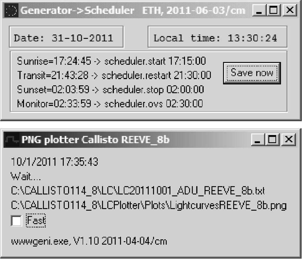
14 Parameter Value Input voltage 12 Vdc nominal (9 to 15 V) Input current 255 ma nominal Weight 0.9 kg Dimensions 200 mm long x 110 mm wide x 82 mm high 27 Operating Software Callisto Software Tools Frequency Genie AutoScheduler WWW Genie Java FITS Viewer FTP WatchDog ~ for sending data to ETH-Zurich SymmTime ~ for synchronizing PC TOD clock 28


15 Callisto 29 Frequency Genie 30

16 AutoScheduler & WWW Genie 31 Java FITS Viewer 32

 (2.0 x 1.")
17 Professionally made printed circuit board (PCB) Silkscreen & soldermask 1.6 mm thick 33 Receiver PCB Requires experience soldering surface mount technology (SMT/SMD) components Most SMT parts are 0805 form factor (0.08 x 0.05 in) (2.0 x 1.3 mm) Components mounted on both sides of PCB 34

18 Tuner Philips CD1316LS/IV-3 45 ~ 870 MHz in 62.5 khz steps 35 Tuner 36


19 Receiver Front and Rear Panels Ready for installation of components Machine cut and silkscreen labels Receiver Front and Rear Panels Connectorized to allow easy PCB removal


20 Finished Receiver ~ Cover Removed 39 Finished Receiver ~ Cover Removed 40


21 Receiver Ready for Use Rear View 41 42


22 43 Create Design CLP5130-1N Log Periodic Dipole Array 50 ~ 1300 MHz 44


23 45 Low Noise Tower-Mounted Amplifier 46


24 Low Noise Tower-Mounted Amplifier Early Prototype 47 Bias-Tee Production Version Amplifier Protector Voltage Regulator Amplifier Lightning Arrestor Bonding & Grounding Provisions for Future 48


25 Voltage Regulator Bypass for 2 nd LNA Bias-Tee RF input + dc to TMA RF to Receiver 49 Noise Figure - Receiver 50

26 Noise Figure Receiver + TMA 51 Bandpass Filter Response 52
27 Sensitivity Limit 53 Spurious Free Dynamic Range (SFDR) 54
 55")
28 Considerable radio frequency interference (RFI) in Anchorage, Alaska Persistent local interference VHF FM broadcast stations 88 ~ 108 MHz VHF TV Broadcast stations 174 ~ 216 MHz UHF TV broadcast stations 450 ~ 600 MHz Cellular base and mobile stations > 865 MHz Spectral overview files and Callisto software tools allow selection of a frequency plan that avoids noisy bands (next slide) 55 Spectral Overview, 45 ~ 870 MHz 56


29 X2.2 Flare on 15 February 2011 FIRST LIGHT Flare occurred less than 24 hours after commissioning the CALLISTO Receiver 57 58
30 59 Description Price (US$) CALLISTO Receiver, complete kit CALLISTO Receiver, partially-built CALLISTO Receiver, ready-built Tower-mounted amplifier (TMA) and LNA power coupler (LPC) AC power adapter (North America only)


31 e-callisto consists of Worldwide network of CALLISTO Receivers, antenna systems and data collection PCs Central data repository at ETH-Zurich in Switzerland All data in public domain CALLISTO Receiver available in kit form, partially-built or ready-built versions 61
Preamplifiers for Callisto Solar Radio Spectrometer
 Preamplifiers for Callisto Solar Radio Spectrometer Whitham Reeve and Christian Monstein 1. Introduction We investigated the performance of three amplifiers (figure 1) for Callisto applications by measuring
Observation of Solar Radio Bursts Using E-CallistoSystem
 43 Observation of Solar Radio Bursts Using E-CallistoSystem J Adassuriya 1*, S Gunasekera 1, KPSC Jayaratne 2, C Monstein 3 1 Arthur C Clarke Institute for Modern Technologies, Katubedda, Moratuwa, Sri
Callisto spectrum measurements in Ootacamund
 Research Collection Report Callisto spectrum measurements in Ootacamund Author(s): Monstein, Christian; Manoharan, P.K.; Nandagopal, D. Publication Date: 2006 Permanent Link: https://doi.org/10.3929/ethz-a-005306639
CLOUDSDR RFSPACE #CONNECTED SOFTWARE DEFINED RADIO. final design might vary without notice
 CLOUDSDR #CONNECTED SOFTWARE DEFINED RADIO final design might vary without notice 1 - PRELIMINARY SPECIFICATIONS http://www.rfspace.com v0.1 RFSPACE CloudSDR CLOUDSDR INTRODUCTION The RFSPACE CloudSDR
(2) Assume the measurements are at 245 MHz, which corresponds to a wavelength of
 Assume the measurements are at 245 MHz, which corresponds to a wavelength of") To Preamplify or Not Whitham D. Reeve and Christian Monstein 1. Introduction A question frequently arises concerning the application of a low noise preamplifier to the Callisto instrument used in the e-callisto
To Preamplify or Not Whitham D. Reeve and Christian Monstein 1. Introduction A question frequently arises concerning the application of a low noise preamplifier to the Callisto instrument used in the e-callisto
May 2012 Solar Activity ~ Radio and Geomagnetic Effects Whitham D. Reeve ( 2012 W. Reeve)
") May 2012 Solar Activity ~ Radio and Geomagnetic Effects Whitham D. Reeve ( 2012 W. Reeve) Abbreviations in this article: ACE: Advanced Composition Explorer AGC: Automatic Gain Control CME: Coronal Mass
May 2012 Solar Activity ~ Radio and Geomagnetic Effects Whitham D. Reeve ( 2012 W. Reeve) Abbreviations in this article: ACE: Advanced Composition Explorer AGC: Automatic Gain Control CME: Coronal Mass
ANTENNAFIER TM 915LTX BLOCK DIAGRAM LNA
 Digitally Tunable 0.5 to 10 Watts This 915 LTX is a Outdoor High Power Digitally Tunable Bi-Directional Amplifier for 802.11b/g WLAN. It s tuned and powered over a 50 Ohm coax. Now you can fine tune your
The Icom PCR-1000 as a SDR RF Front End OscarOnline.org David Carr, KD5QGR partially based on a document by Edgar J. Kaiser, DF2MZ
 The Icom PCR-1000 as a SDR RF Front End OscarOnline.org David Carr, KD5QGR partially based on a document by Edgar J. Kaiser, DF2MZ Purpose: Many times when working in software defined radio some means
TECHNICAL NOTES. MT-4 Radio Systems. TN247 VR-4E VHF MT-4E Receiver. Specifications. Models Available. Receiver Operating Frequency
 MADE IN CANADA TN247 VR-4E VHF MT-4E Receiver USB CNTL BUS A D RECEIVER FREQUENCY (MHz) SQ. DISABLE NORM OFF REF IN RF IN The VR-4E VHF receiver is an FM radio module capable of analog operation in 12.5
ELEN 701 RF & Microwave Systems Engineering. Lecture 2 September 27, 2006 Dr. Michael Thorburn Santa Clara University
 ELEN 701 RF & Microwave Systems Engineering Lecture 2 September 27, 2006 Dr. Michael Thorburn Santa Clara University Lecture 2 Radio Architecture and Design Considerations, Part I Architecture Superheterodyne
NetSDR. Wideband Digital Radio User s Guide Firmware Revision 1.07 & 1.08 FPGA Revision 3 & 4. Type to enter text
 1 NetSDR Wideband Digital Radio User s Guide Firmware Revision 1.07 & 1.08 FPGA Revision 3 & 4 Type to enter text 2 Table of Contents Legal Notices 3 Supplied Accessories 4 Precautions 5 Hardware 6 Introduction
DEVELOPMENT OF SOFTWARE RADIO PROTOTYPE
 DEVELOPMENT OF SOFTWARE RADIO PROTOTYPE Isao TESHIMA; Kenji TAKAHASHI; Yasutaka KIKUCHI; Satoru NAKAMURA; Mitsuyuki GOAMI; Communication Systems Development Group, Hitachi Kokusai Electric Inc., Tokyo,
Radio observation of SMART-1 in its last perilune orbit
 Research Collection Report Radio observation of SMART-1 in its last perilune orbit Author(s): Monstein, Christian A. Publication Date: 2006 Permanent Link: https://doi.org/10.3929/ethz-a-005238194 Rights
Integrated receivers for mid-band SKA. Suzy Jackson Engineer, Australia Telescope National Facility
 Integrated receivers for mid-band SKA Suzy Jackson Engineer, Australia Telescope National Facility ASKAP/SKA Special Technical Brief 23 rd October, 2009 Talk overview Mid band SKA receiver challenges ASKAP
See last page for document revision number. Image source: NASA
 See last page for document revision number Image source: NASA CALLISTO-NA Construction Manual Table of Contents Section Page I. Description... II. General Building Tips...4 III. Intermediate Frequency
Preliminary Product Overview
 Preliminary Product Overview Features DC to > 3 GHz Frequency Range 25 Watt (CW), 200W (Pulsed) Max Power Handling Low On-State Insertion Loss, typical 0.3 db @ 3 GHz Low On-State Resistance < 0.75 Ω 25dB
SDR-14 User s Guide Version 1.2 Software Defined Receiver & Spectrum Analyzer
 SDR-14 User s Guide Version 1.2 Software Defined Receiver & Spectrum Analyzer Software Defined Receiver & Spectrum Analyzer 2004 RFSPACE. All rights reserved. 2 TABLE OF CONTENTS PACKAGE CONTENTS..3 GETTING
RF Tuning Range. Intermediate Frequencies. The RF tuning range of the SDRplay module is detailed below.
 The SDR-play RSP1 is a powerful wideband full-featured SDR which coers all frequencies from 1 khz up to 2 GHz. All it needs is a PC and an antenna to proide excellent communications receier functionality.
Software Defined Radios
 Software Defined Radios What Is the SDR Radio? An SDR in general is a radio that has: Primary Functionality [modulation and demodulation, filtering, etc.] defined in software. DSP algorithms implemented
SIMPLE Raspberry Pi VHF TRANSCEIVER & TNC
 Simple Circuits Inc. SIMPLE Raspberry Pi VHF TRANSCEIVER & TNC 2 Meter Transceiver & TNC Simple Circuits Inc. 2015-2018 4/1/2018 Simple Raspberry Pi VHF Transceiver and TNC Introduction: This document
SPECIAL SPECIFICATION 6744 Spread Spectrum Radio
 2004 Specifications CSJ 0924-06-244 SPECIAL SPECIFICATION 6744 Spread Spectrum Radio 1. Description. Furnish and install spread spectrum radio system. 2. Materials. Supply complete manufacturer specifications
Preliminary features of the SDR-X receiver SDR-X , PowerSDR Winrad Winrad DDS SFDR SFDR AD995 AD99 1
 Preliminary features of the SDR-X receiver The SDR-X receiver, in its full version is capable of continuously tuning the entire HF spectrum, 6m ( 50-52 MHz) band included. SSB, AM etc. demodulation, bandpass
Antennas and Propagation Chapters T4, G7, G8 Antenna Fundamentals, More Antenna Types, Feed lines and Measurements, Propagation
 Antennas and Propagation Chapters T4, G7, G8 Antenna Fundamentals, More Antenna Types, Feed lines and Measurements, Propagation =============================================================== Antenna Fundamentals
R&S FPC-Z10 Teaching Kit Getting Started
 R&S FPC-Z10 Teaching Kit Getting Started 1178843602 Getting Started Version 04 This manual describes the following products: R&S FPC-Z10 Teaching Kit (1328.7338.02) 2018 Rohde & Schwarz GmbH & Co. KG Mühldorfstr.
144MHz direct conversion receiver with I/Q outputs for use with Software Defined Radio.
 144MHz direct conversion receiver with I/Q outputs for use with Software Defined Radio. Overview This design is a direct conversion receiver for 144MHz with quadrature outputs for use either with a software
Cohoe Radio Observatory, Alaska ~ Part 4, Callisto Antenna System
 Cohoe Radio Observatory, Alaska ~ Part 4, Callisto Antenna System Whitham D. Reeve 1. Introduction This series of articles describes construction of a new radio observatory in Cohoe, Alaska (see section
Advanced Test Equipment Rentals ATEC (2832)
") Established 1981 Advanced Test Equipment Rentals www.atecorp.com 800-404-ATEC (2832) LOG PERIODIC DIPOLES 20 MHz - 18 GHz TRANSMIT - RECEIVE SPECIFICATIONS ELECTRICAL Impedance: 50 ohms INDIVIDUALLY CALIBRATED
Established 1981 Advanced Test Equipment Rentals www.atecorp.com 800-404-ATEC (2832) LOG PERIODIC DIPOLES 20 MHz - 18 GHz TRANSMIT - RECEIVE SPECIFICATIONS ELECTRICAL Impedance: 50 ohms INDIVIDUALLY CALIBRATED
MWA REVB LNA Measurements
 1 MWA REVB LNA Measurements Hamdi Mani, Judd Bowman Abstract The MWA LNA (REVB) was measured on the Low Frequency Radio astronomy Lab using state of the art test equipment. S-parameters of the amplifier
PLANAR S5048 and TR5048
 PLANAR S5048 and TR5048 Vector Network Analyzers KEY FEATURES Frequency range: 20 khz 4.8 GHz COM/DCOM compatible for LabView Measured parameters: and automation programming S11, S12, S21, S22 (S5048)
Vector Network Analyzers. Paul Coverdale VE3ICV
 Paul Coverdale VE3ICV What is a vector network analyzer? What is a vector? A vector is a quantity having magnitude and direction A vector can be described in rectangular (X,Y) or polar ( Z θ) notation
Data Sheet SC5317 & SC5318A. 6 GHz to 26.5 GHz RF Downconverter SignalCore, Inc. All Rights Reserved
 Data Sheet SC5317 & SC5318A 6 GHz to 26.5 GHz RF Downconverter www.signalcore.com 2018 SignalCore, Inc. All Rights Reserved Definition of Terms 1 Table of Contents 1. Definition of Terms... 2 2. Description...
LNS ultra low phase noise Synthesizer 8 MHz to 18 GHz
 LNS ultra low phase noise Synthesizer 8 MHz to 18 GHz Datasheet The LNS is an easy to use 18 GHz synthesizer that exhibits outstanding phase noise and jitter performance in a 3U rack mountable chassis.
Antenna and Analog Beamformer
 Antenna and Analog Beamformer Requirements The antenna system is responsible for collecting radiation from the sky and presenting a suitably conditioned 80-300 MHz RF signal to the receiver node. Because
VHF/UHF Wideband ViXIceptor WJ-8621
 Developmental Specification WATKINS-JOHNSON May 1997 VHF/UHF Wideband ViXIceptor WJ-8621 The WJ-8621 is a general-purpose VHF/UHF receiver covering a 20 to 2700 MHz frequency range. WJ packages the unit
Compact Series: S5048 & TR5048 Vector Network Analyzers KEY FEATURES
 Compact Series: S5048 & TR5048 Vector Network Analyzers KEY FEATURES Frequency range: 20 khz - 4.8 GHz Measured parameters: S11, S12, S21, S22 (S5048) S11, S21 (TR5048) Wide output power adjustment range:
02680SX Series UHF Mount Dipole Array Series
 02680SX Series UHF Mount Dipole Array Series Page 1 of 11 Description The 02680SX series antennas are 0dB, 3dB and 6dB Gain, Stainless Steel Side Mount Dipole Array antennas, for use in the Commercial
R&D White Paper WHP 066. Specifying UHF active antennas and calculating system performance. Research & Development BRITISH BROADCASTING CORPORATION
 R&D White Paper WHP 066 July 2003 Specifying UHF active antennas and calculating system performance J. Salter Research & Development BRITISH BROADCASTING CORPORATION BBC Research & Development White Paper
UHFSDR + USB2SDR = Flexible IF Rig
 UHFSDR + USB2SDR = Flexible IF Rig Eric Haskell KC4YOE WWW..ORG 1 Wanted IF rig SDR Buildable Simple Frequency flexibility Why UHFSDR? Enter UHFSDR 1.75-700MHz (1/2 Si570 output) 50 mw Transmit out 2dB
RF Interface Reference
 5 RF Interface Reference In This Chapter: RF Interface Details, 32 RF and IF Interfaces, 33 Pulse Width Modulation, 35 Power, Ground and Clock, 36 Bypassing the Analog Chain, 37 Receive Section Modifications,
Valon Synthesizer RFI Test Report
 Page: Page 1 of 10 VEGAS-003-A-REP Version: A Prepared By: Name(s) and Signature(s) Organization Date C.Beaudet NRAO-GB 2011-11-29 J.Ray NRAO-GB 2013-03-18 Page: Page 2 of 10 Change Record Version Date
Technical Data. Digital VXI VHF/UHF Receiver WJ-8629 WATKINS-JOHNSON
 Technical Data WATKINS-JOHNSON January 1997 Digital VXI VHF/UHF Receiver WJ-8629 The WJ-8629 is a general-purpose VHF/UHF receiver covering a 20 to 2700 MHz frequency range that utilizes Digital Signal
On site RF troubleshooting for installation and maintenance
 On site RF troubleshooting for installation and maintenance Measure of interferers, high power for microwave links or low power for Base Stations uplink Troubleshooting of cables, or waveguides, and antennas
Software Defined Radio. Bella Vista Radio Club 1 February 2018
 Software Defined Radio Bella Vista Radio Club 1 February 2018 Agenda for Software Defined Radio (SDR) What is it? How does it work? Demonstration. How do you hook it up? What hardware is available (Cost)?
PLANAR 814/1. Vector Network Analyzer
 PLANAR 814/1 Vector Network Analyzer Frequency range: 100 khz 8 GHz Measured parameters: S11, S12, S21, S22 Wide output power range: -60 dbm to +10 dbm >150 db dynamic range (1 Hz IF bandwidth) Direct
Integrated receivers for mid-band SKA. Suzy Jackson Engineer, Australia Telescope National Facility
 Integrated receivers for mid-band SKA Suzy Jackson Engineer, Australia Telescope National Facility SKADS FP6 Meeting Chateau de Limelette 4-6 November, 2009 Talk overview Mid band SKA receiver challenges
3250 Series Spectrum Analyzer
 The most important thing we build is trust ADVANCED ELECTRONIC SOLUTIONS AVIATION SERVICES COMMUNICATIONS AND CONNECTIVITY MISSION SYSTEMS 3250 Series Spectrum Analyzer > Agenda Introduction
AVL-10000T AUDIO VIDEO LINK TRANSMITTER TECHNICAL MANUAL
 AVL-10000T AUDIO VIDEO LINK TRANSMITTER TECHNICAL MANUAL Document : AVL-10000T Version: 1.00 Author: Henry S Date: 25 July 2008 This module contains protection circuitry to guard against damage due to
FCC ID: A3LSLS-BD106Q. Report No.: HCT-RF-1801-FC003. Plot Data for Output Port 2_QPSK 9 khz ~ 150 khz Middle channel 150 khz ~ 30 MHz Low channel
 Plot Data for Output Port 2_QPSK 9 khz ~ 150 khz Middle channel 150 khz ~ 30 MHz Low channel 30 MHz ~ 1 GHz Middle channel 1 GHz ~ 2.491 GHz Low channel 2.695 GHz ~ 12.75 GHz High channel 12.75 GHz ~ 26.5
Technical Equipment Specification
 STATE OF CALIFORNIA Office of the State Chief Information Officer Public Safety Communications Division Technical Equipment Specification Equipment Type: Transmitter/Receiver Mobile Relay/Base/Control
S O P H I S T I C A T E D A U T O M A T I O N
 S O P H I S T I C A T E D A U T O M A T I O N Introduction Cost-effective Radio modems to any serial communication application Low power models, different frequency ranges RS232 / / RS422 / 5V TTL interface
Spectrum Analyzers R3132/3132N/3162 R3132/3132N/3162. Low cost, high performance. General-Purpose Spectrum Analyzer Adaptable to Various Applications
 Frequency band R3132 9 khz to 3 GHz R3132N:9 khz to 3 GHz R3162: 9 khz to 8 GHz High signal purity: -105 dbc (20 khz offset) Total level accuracy: ±1.5 db High speed GPIB useful for high speed productions
Instruction Manual. Quadrature Tower Mounted Amplifier TMA2Q & LNA Power Coupler LPC2Q. Copyright 2016 W. Reeve
 Instruction Manual Quadrature Tower Mounted Amplifier TMA2Q & LNA Power Coupler LPC2Q Copyright 2016 W. Reeve See last page for document revision information TMA2Q & LPC2Q Instruction Manual Table of Contents
RADIO RECEIVERS ECE 3103 WIRELESS COMMUNICATION SYSTEMS
 RADIO RECEIVERS ECE 3103 WIRELESS COMMUNICATION SYSTEMS FUNCTIONS OF A RADIO RECEIVER The main functions of a radio receiver are: 1. To intercept the RF signal by using the receiver antenna 2. Select the
Compact Series: S5065 & S5085 Vector Network Analyzers KEY FEATURES
 Compact Series: S5065 & S5085 Vector Network Analyzers KEY FEATURES Frequency range: 9 khz - 6.5 or 8.5 GHz Measured parameters: S11, S12, S21, S22 Wide output power adjustment range: -50 dbm to +5 dbm
ICOM IC-R8600 Specifications, Features & Options
 General Frequency coverage IC-R8600 USA: 0.010000 821.999999MHz*, 851.000000 866.999999MHz, 896.000000 3000.000000MHz (*Guaranteed range: 0.100000 821.999999MHz) Antenna connector Frequency stability Mode
mat-30 HF-SSB Automatic Antenna Tuner Instruction Manual Version V1.0
 INTRODUCTION mat-30 HF-SSB Automatic Antenna Tuner Instruction Manual Version V1.0 The mat-30 is an automatic tuner intended for use with modern Yaesu transceivers. It works with some Yaesu transceiver
THE ARO 1.3mm IMAGE-SEPARATING MIXER RECEIVER SYSTEM. Revision 1.0
 THE ARO 1.3mm IMAGE-SEPARATING MIXER RECEIVER SYSTEM Revision 1.0 September, 2006 Table of Contents 1 System Overview... 3 1.1 Front-End Block Diagram... 5 1.2 IF System... 6 2 OPERATING PROCEDURES...
VLF-LF Up Converter 5KHz - 500KHz. User manual. Rev HEROS technology Limited All rights reserved
 VLF-LF Up Converter 5KHz - 500KHz User manual. Rev 2016-02 Since many countries are allocating the 472 khz to 479kHZ band for experimental use by Radio Amateurs, a growing number of them as well as listeners
Impedance 50 (75 connectors via adapters)
") VECTOR NETWORK ANALYZER PLANAR 304/1 DATA SHEET Frequency range: 300 khz to 3.2 GHz Measured parameters: S11, S21, S12, S22 Dynamic range of transmission measurement magnitude: 135 db Measurement time
VECTOR NETWORK ANALYZER PLANAR 304/1 DATA SHEET Frequency range: 300 khz to 3.2 GHz Measured parameters: S11, S21, S12, S22 Dynamic range of transmission measurement magnitude: 135 db Measurement time
Green ADVANTAGES. Spectrum Analyzer Two models available: 24 GHz and 8 GHz SPECTRUM ANALYZER. Antenna Panel Inputs. Auxiliary Antenna Inputs OSCOR
 Whip antenna extension connector Auto Switching (utilizes 5 independent antennas) Green ADVANTAGES OSCOR FULL 24 GHz COVERAGE Headphone Jack SWEEPS FROM 10 khz TO 24 GHz AT 12.2 khz STEPS IN LESS THAN
TECHNICAL SPECIFICATION FOR RF (TEST &MEASUREMENT) DEVICE
 DEVICE") TECHNICAL SPECIFICATION FOR RF (TEST &MEASUREMENT) DEVICE Test and measuring device supports the following measurement functions: A- Cable and Antenna Analyzer, 2 MHz to 4 GHz. B- Spectrum Analyzer, 100
TECHNICAL SPECIFICATION FOR RF (TEST &MEASUREMENT) DEVICE Test and measuring device supports the following measurement functions: A- Cable and Antenna Analyzer, 2 MHz to 4 GHz. B- Spectrum Analyzer, 100
Radio Receivers. Al Penney VO1NO
 Radio Receivers Role of the Receiver The Antenna must capture the radio wave. The desired frequency must be selected from all the EM waves captured by the antenna. The selected signal is usually very weak
Overview of the MSA 12/30/10
 Overview of the MSA 12/30/10 Introduction The purpose of this document is to provide an overview of the capabilities and construction of the MSA to help potential builders get oriented. Much more detailed
GPS Time and Frequency Reference Receiver
 $ GPS Time and Frequency Reference Receiver Symmetricom s 58540A GPS time and frequency reference receiver features: Eight-channel, parallel tracking GPS engine C/A Code, L1 Carrier GPS T-RAIM satellite
VLF LF 10KHz - 500KHz Up Converter. Brochure. HEROS technology Limited All rights reserved
 Brochure Since many countries are allocating the old 500KHz (600m) maritime radio distress band for experimental use by Radio Amateurs, a growing number of them as well as listeners have become interested
Production Test and Spectral Monitoring
 1 Production Test and Spectral Monitoring Stephen Plumb Key RF Building Blocks Symbol Name Types Function Amplifier (2 port) Power Amplifier Low Noise Amplifier Amplify signal before transmission (high
Model AAA-1C. Addendum to AAA-1B documentation
 Model AAA-1C. Addendum to AAA-1B documentation 1. Specifications for Model AAA-1C (11) General Output impedance Power supply (1) Maximal output voltage (10) Physical size 50 Ohms, BNC connector on control
GAUSS High Power UHF Radio
 [] Table of contents Table of contents... 1 1. Introduction... 3 Features... 4 Block Diagram... 6 2. Pinouts... 7 3. Absolute Maximum Ratings... 9 4. General Recommended Operating Conditions... 10 5. RF
INSTRUCTION SHEET WIDEBAND POWER SENSOR MODEL Copyright 2008 by Bird Electronic Corporation Instruction Book P/N Rev.
 INSTRUCTION SHEET WIDEBAND POWER SENSOR MODEL 5012 Copyright 2008 by Bird Electronic Corporation Instruction Book P/N 920-5012 Rev. C Description The Bird 5012 Wideband Power Sensor (WPS) is a Thruline
SCA COMPATIBLE SOFTWARE DEFINED WIDEBAND RECEIVER FOR REAL TIME ENERGY DETECTION AND MODULATION RECOGNITION
 SCA COMPATIBLE SOFTWARE DEFINED WIDEBAND RECEIVER FOR REAL TIME ENERGY DETECTION AND MODULATION RECOGNITION Peter Andreadis, Martin Phisel, Robin Addison CRC, Ottawa, Canada (peter.andreadis@crc.ca ) Luca
Product Catalog Spring 2017 AmericanAmpTech.com
 Innovative Ideas, Quality Products, Competitive Prices Product Catalog Spring 2017 AmericanAmpTech.com TABLE OF CONTENTS... 3 FM Transmitters & Amplifiers... 4 IPA Modules... 6 FM Bandpass Filters... 7
PNA Family Microwave Network Analyzers (N522x/3x/4xB) CONFIGURATION GUIDE
 CONFIGURATION GUIDE") PNA Family Microwave Network Analyzers (N522x/3x/4xB) CONFIGURATION GUIDE Table of Contents PNA Family Network Analyzer Configurations... 05 Test set and power configuration options...05 Hardware options...
PNA Family Microwave Network Analyzers (N522x/3x/4xB) CONFIGURATION GUIDE Table of Contents PNA Family Network Analyzer Configurations... 05 Test set and power configuration options...05 Hardware options...
Wavedancer A new ultra low power ISM band transceiver RFIC
 Wavedancer 400 - A new ultra low power ISM band transceiver RFIC R.W.S. Harrison, Dr. M. Hickson Roke Manor Research Ltd, Old Salisbury Lane, Romsey, Hampshire, SO51 0ZN. e-mail: roscoe.harrison@roke.co.uk
RF/IF Terminology and Specs
 RF/IF Terminology and Specs Contributors: Brad Brannon John Greichen Leo McHugh Eamon Nash Eberhard Brunner 1 Terminology LNA - Low-Noise Amplifier. A specialized amplifier to boost the very small received
Major Products. RF/Microwave provider
 Major Products Products 1 RF Sub-systems Combiner FEU TTA TMA SCU 2 Products 2 RF components Power Splitter (BTS) Filter Switch Coupler 3 Feature1 Divider Frequency Range 824~894, 1750~1870, 1885~2170,
RF System Aspects for SDR. A Tutorial. Dr. Ruediger Leschhorn, Rohde & Schwarz 29. November 2011
 RF System Aspects for SDR A Tutorial Dr. Ruediger Leschhorn, Rohde & Schwarz 29. November 2011 Content Radio System Some Basics Link Budget Cosite Examples Desensitization Blocking, Transmitter Noise,
A Selection of R.F. Wattmeters optimized for console, remote, and mobile applications.
 Watt/SWR Meter (2 and 4 channel products Peak/Average on forward and Reflected). Modulation Scope. (All models) Modulation Spectrum Analyzer. (All models) Station Voltage/Current Monitor (WN-2 only). Four
On-the-Air Demonstration of a Prototype LWA Analog Signal Path
 On-the-Air Demonstration of a Prototype LWA Analog Signal Path Joe Craig, Mahmud Harun, Steve Ellingson April 12, 2008 Contents 1 Summary 2 2 System Description 2 3 Field Demonstration 3 University of
Multi-Function Assemblies
 K&L Microwave offers a variety of (MFA) products to satisfy a broad range of filtering applications. Many applications require frequency pre-selection at the front end of the communication or test and
by Cliff Pulis, KE0CP SDR Presentation - Cliff Pulis, KE0CP 1
 by Cliff Pulis, KE0CP SDR Presentation - Cliff Pulis, KE0CP 1 Basic Receiver Principles Mixing Frequencies Hetrodyn ing The IF Amplifier SDR Principles & Quadrature Phase (IQ) VHF / UHF DVB-T Dongle SDR
6.976 High Speed Communication Circuits and Systems Lecture 20 Performance Measures of Wireless Communication
 6.976 High Speed Communication Circuits and Systems Lecture 20 Performance Measures of Wireless Communication Michael Perrott Massachusetts Institute of Technology Copyright 2003 by Michael H. Perrott
TRANSCOM Manufacturing & Education
 www.transcomwireless.com 1 G6 Vector Signal Generator Overview G6 Vector Signal Generator is a high performance vector signal generator. It can generate arbitrary wave signal, continuous wave signal, common
Tunable Wideband & Ultra-Wideband Multi- Antenna Transceivers with Integrated Recording, Playback & Processing
 2016 Multi-Antenna Transceiver Systems Tunable Wideband & Ultra-Wideband Multi- Antenna Transceivers with Integrated Recording, Playback & Processing --- For ES, DF, COMS & EA 1 Multi-Antenna Systems D-TA
PTX-0350 RF UPCONVERTER, MHz
 PTX-0350 RF UPCONVERTER, 300 5000 MHz OPERATING MODES I/Q upconverter RF = LO + IF upconverter RF = LO - IF upconverter Synthesizer 10 MHz REFERENCE INPUT/OUTPUT EXTERNAL LOCAL OSCILLATOR INPUT I/Q BASEBAND
Demo Circuit DC550A Quick Start Guide.
 May 12, 2004 Demo Circuit DC550A. Introduction Demo circuit DC550A demonstrates operation of the LT5514 IC, a DC-850MHz bandwidth open loop transconductance amplifier with high impedance open collector
Model 865-M Wideband Synthesizer
 Model 865-M Wideband Synthesizer Features Wideband Low phase noise Fast switching down to 20 µs FM, Chirps, Pulse Internal OCXO, external variable reference Single DC supply Applications ATE LO for frequency
DC Injector (Bias Tee) kit. Technical Manual
 kit. Technical Manual") DC Injector (Bias Tee) kit Technical Manual Document Author Dave Powis, G4HUP Date 7 Jan 2017 Version Issue 2_0 Document Ref HUP-05-020 http://huprf.com Tel +44 (0)1473 737717 g4hup@outlook.com Contents
DC Injector (Bias Tee) kit Technical Manual Document Author Dave Powis, G4HUP Date 7 Jan 2017 Version Issue 2_0 Document Ref HUP-05-020 http://huprf.com Tel +44 (0)1473 737717 g4hup@outlook.com Contents
Designing a 2 GHz to 10 GHz Vector Reflectometer. Jonathan Klein, University of Alaska, Fairbanks
 Designing a 2 GHz to 10 GHz Vector Reflectometer Jonathan Klein, University of Alaska, Fairbanks A vector reflectometer measures reflection as a function of frequency. a1 Z0 A vector reflectometer measures
Spectrum Analyzer. Spectrum Analyzer. Antenna Panel Inputs. Auxiliary Antenna Inputs. Two models available: 24 GHz and 8 GHz OSCOR
 Whip antenna extension connector Auto Switching (utilizes 5 independent antennas) OSCOR ADVANTAGES FULL 24 GHz COVERAGE Headphone Jack SWEEPS FROM 10 khz TO 24 GHz AT 12.2 khz STEPS IN LESS THAN 1 SECOND
Design and Development of Data Acquisition System for Solar Radiation using LPDA Antenna and CALLISTO
 Journal of Basic Sciences, 2015, 3, 1-6. Design and Development of Data Acquisition System for Solar Radiation using LPDA Antenna and CALLISTO Vijay S. Kale *, Dnyandev B. Patil, Madan B. Matsagar Associate
HF Receivers, Part 2
 HF Receivers, Part 2 Superhet building blocks: AM, SSB/CW, FM receivers Adam Farson VA7OJ View an excellent tutorial on receivers NSARC HF Operators HF Receivers 2 1 The RF Amplifier (Preamp)! Typical
LOW NOISE BLOCKDOWN CONVERTER
 LOW NOISE BLOCKDOWN CONVERTER Europe: LNB for Broadcasting Satellite (1) Wide band type receiving all broadcasting channels (analog & digital) of Europe. [Universal LNB] (2) Originally developed feed-horn
Programmable Active Crystal Filters Catalog
 Programmable Active Crystal Filters Catalog www.fiplex.com AERONAUTICAL BAND PROGRAMMABLE ACTIVE CRYSTAL FILTER* 118-137 MHz ACFA1-25 Crystal filter based filtering system, 25 KHz BW Software programmable
PRODUCTS BROCHURE PRODUCTS OVERVIEW
 PRODUCTS BROCHURE WELCOME TO MOUNTAIN RF Mountain RF Sensors is engaged in the design and manufacture of specialty radio frequency (RF) products for government and military customers. The company is geared
Pure Signal Digital. Vector network analyzer. and many more unmatched features
 HF+6M Multimode SDR Transceiver LunarisSDR 610 + VNA Pure Signal Digital PreDistortion Compatible Vector network analyzer and many more unmatched features PRESENTS Lunaris-SDR is a single board Digital
Receiver Architecture
 Receiver Architecture Receiver basics Channel selection why not at RF? BPF first or LNA first? Direct digitization of RF signal Receiver architectures Sub-sampling receiver noise problem Heterodyne receiver
SDR_Ursinho Design, Simulation and Assembly of a Direct Conversion High Frequency SDR Software Defined Receiver. Jeremy Clark VE3PKC
 SDR_Ursinho Design, Simulation and Assembly of a Direct Conversion High Frequency SDR Software Defined Receiver Jeremy Clark VE3PKC Copyright Information /Jeremy Clark/August 2016 All rights reserved.
Input Return Loss, db > 26 Narrowband to Narrowband Isolation, db > 30
 Band III (VHF) TV Commutating Line Combiner 174-222 MHz CC VHF Series This style of circuit provides a relatively low cost combiner which is ideal, provided the frequency spacing is not too close. Compact,
SATELLITE GROUND SEGMENT
 WWW.BHE-MW.EU www.bhe-mw.eu 2 DEAR READERS, PARTNERS, This overview is not a product catalogue. The main aim of this brochure is to provide a short summary about our products, services and capabilities.
ASPiSYS DQAM AM Stereo Decoder
 DQAM A C-QUAM AM Stereo Decoder ASPiSYS DQAM AM Stereo Decoder This is a high-quality decoder board for converting regular AM radios to C-QUAM compatible stereo AM radios. You can now upgrade your radio