A Selection of R.F. Wattmeters optimized for console, remote, and mobile applications.
|
|
|
- Donald Kelly
- 5 years ago
- Views:
Transcription
 Station Voltage/Current Monitor (WN-2 only). Four Auxiliary voltage Inputs (WN-2 and WN-2d). Digital Input/Output Monitors (WN-2 and WN-2d).")
1 Watt/SWR Meter (2 and 4 channel products Peak/Average on forward and Reflected). Modulation Scope. (All models) Modulation Spectrum Analyzer. (All models) Station Voltage/Current Monitor (WN-2 only). Four Auxiliary voltage Inputs (WN-2 and WN-2d). Digital Input/Output Monitors (WN-2 and WN-2d). 1

2 A Selection of R.F. Wattmeters optimized for console, remote, and mobile applications. 2


3 WaveNode WN-2 ( 4 Sensors) Front View with RF present showing bargraph and Peak, Average and SWR Rear View showing coax sensor inputs Other connections for power input, SWR relay connector, Remote serial port, User I/O and USB port 3


4 WaveNode WN-2d ( 4 Sensors) Front View with Peak power and S.W.R. LED Bargraphs. Top bargraph displays peak power. The scale is user selectable for each of the four thruline sensors installed. Rear View with Sensor Inputs, Auxiliary inputs, and USB Interface. Bottom bargraph shows SWR on 1:1 -> 10:1 scale. 4


5 WaveNode WN-2m (2 sensors) Various mounting options On Optional Pedestal Tilted Viewing angle Internal Connectors Tilted Viewing angle..external Connectors Showing Internal Connectors,, Top or Bottom Cable Exit 5


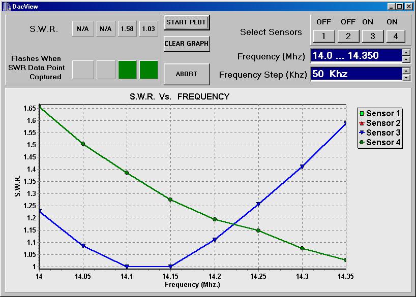
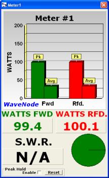
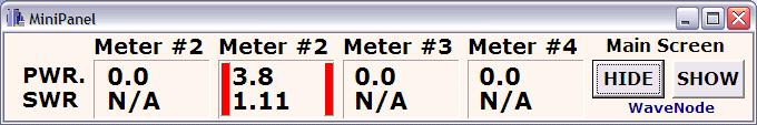
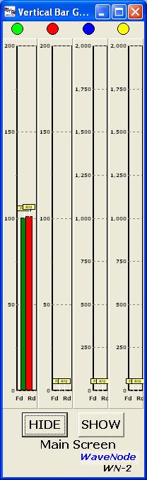
6 Graphical Views Optimized for You 6
7 WaveNode products fill the gap between laboratory R.F. Instruments and simple Digital Wattmeter Simultaneous monitoring of RF power/swr on two or four separate coax sensors. Calculates SWR, peak and average power for display on the built-in LCD display. Bargraph displays of peak power are shown when the RF power exceeds 2 watts. Direct USB computer interface on all products for Microsoft OS XP, 7, Vista, 8 and bit RISC microprocessor, 12-bit A/D converter, and precision peak/ average detection circuitry for each sensor. 40 Khz sampling of the RF envelope provides a digital Oscilloscope view of the modulation envelope Spectrum Analysis monitors the data content and bandwidth of the modulation speech or data stream. Monitor Intermodulation and splatter real-time as you operate. Additional monitoring circuitry is provided for station DC voltage/current (WN-2). Four digital outputs allow monitoring and control with remote PC (WN-2 and WN-2d). Four additional analog inputs allow real-time monitoring on the local LCD display or remotely through USB interconnect to a host PC (WN-2 and WN-2d). Relay provided to trigger on excess SWR for equipment protection (WN-2 and WN-2d only). All data viewing and control can be done locally or remotely via PC. 7
 AM-1: 0-2000 Watts (500KHz-3.0 MHz.) L/M-1: 0-2000 Watts (100KHz-5 MHz ) ~~~~~~~~~~~~~~~ UHF-1: 0-300 Watts (120-470 MHz.) UHF-2KW: 0-2000 Watts (120-170 MHz.) UHF-220: 0-2000 Watts (200-275 MHz.")
8 Sensor Selection Choice of SO-239 or N type RF Connectors HF-1: 0-2,000 Watts ( MHz.) LP-1: 0-60 Watts ( MHz.) 8KW: 0-8,000 Watts ( MHz.) FM-1: Watts ( MHz.) AM-1: Watts (500KHz-3.0 MHz.) L/M-1: Watts (100KHz-5 MHz ) ~~~~~~~~~~~~~~~ UHF-1: Watts ( MHz.) UHF-2KW: Watts ( MHz.) UHF-220: Watts ( MHz.) UHF-70cm: Watts ( MHz.) ~~~~~~~~~~~~~~~ SHF-1: Watts ( MHz.) SHF-2: Watts ( MHz.) SHF-3: Watts (950 MHz MHz.) 8

9 Test/Calibration NIST traceable Calibration with HP Model 437B power meter and matching 8482B Detector. 9
10 Sensing Block Diagram 10
11 Peak Detection Peak capture, conversion, Reset 20 times per second. Each Sample is Independent of the Previous. Peak Follow A/D Convert Reset Peak Detector (Trisetime = 150 microsecond) Forward Voltage from Coax Sensor D1 DIODE R1 C1 To A/D Converter 1 2 Rese t( 10 microsecond pulse) Simplified schematic of Peak Detector. 11

12 Average Power easurement 8 Hz Lowpass filter. 20 Sample/second f s. Basic Rule: Don t violate Nyquist sampling criteria to obtain accurate results. Low-Pas s Input from Coax Sensor 8 Hz Lowpass Filter (1st Orde r) To A/D Converter 12
13 Modulation Scope Modulation pattern on SSB. Scope shows actual RF Voltage at the coax in Volts Peak-Peak. The scope hardware/software is in the WN-2. Your soundcard is NOT used. 13
14 Spectrum Analyser The Spectrum Analyzer provides DC to 20 KHz modulation analysis. Has the features found in a laboratory Instrument for sound/distortion Analysis. 14


15 Test Tones Menu Uses your sound card and Rigblaster (or equivalent) to provide Sine, Pulse+Sine, Dual Tones for measuring IM, transmitted bandwidth, and Messages. Pressing the button activates the tone for 3 seconds, and the results can be viewed on the Spectrum Analyser or Oscilloscope. Perfect for observing Linear Amplifier output without the use of a function generator. Question: Why pulse+sine Modulation? Answer: The pulse energy spreads audio energy from 0-20Khz into the input, and allows observation of the transmitter bandwidth immediately with the Spectrum Analyser. Pulse + Sine function Input 15
16 QuickView Modulation Spectrum For realtime, continuous monitoring Fast,continuous viewing of IM and Splatter components into adjacent frequencies. The energy is divided into 400Hz segments and compared to DC -3 KHz energy. A typical SSB energy spectrum 16

17 Optional Yaesu Rotator Control Single/ Dual Rotator Control and View Map View Customized to your QTH No Alignment necessary. Click on Map to Send your Rotator to a new Position 17
18 Review Expandable Real-time R.F. Diagnostic and Monitor tools Commercial, rugged construction. Software upgrades are always provided free of charge on our website. Add sensors, rotator controller, or other accessories as you need them. 18
TelePost LP-500 Digital Station Monitor
 TelePost LP-500 Digital Station Monitor Reviewed by Martin Ewing, AA6E aa6e@arrl.net In the United States, the Federal Communications Commission (FCC) requires us to operate in accordance with good engineering
P3 Panadapter Transmit Monitor Option Frequently Asked Questions Rev B, Aug 2016
 P3 Panadapter Transmit Monitor Option Frequently Asked Questions Rev B, Aug 2016 Copyright 2016, Elecraft, Inc. All Rights Reserved Technical and Configuration Details 1. How does the P3 monitor my transmit
mat-30 HF-SSB Automatic Antenna Tuner Instruction Manual Version V1.0
 INTRODUCTION mat-30 HF-SSB Automatic Antenna Tuner Instruction Manual Version V1.0 The mat-30 is an automatic tuner intended for use with modern Yaesu transceivers. It works with some Yaesu transceiver
Test Equipment. PHYS 401 Physics of Ham Radio
 Test Equipment Voltmeter - an instrument that is used to measure voltage. It is used in parallel with a circuit to be measured. a series resistor extends the range of the meter. Ammeter - an instrument
INSTRUCTION SHEET WIDEBAND POWER SENSOR MODEL Copyright 2008 by Bird Electronic Corporation Instruction Book P/N Rev.
 INSTRUCTION SHEET WIDEBAND POWER SENSOR MODEL 5012 Copyright 2008 by Bird Electronic Corporation Instruction Book P/N 920-5012 Rev. C Description The Bird 5012 Wideband Power Sensor (WPS) is a Thruline
PowerMonitor III. Digital Power and SWR meter for HF bands
 PowerMonitor III Digital Power and SWR meter for HF bands 2016 Power Monitor III is an accurate Power and SWR meter as well a protective device. PTT line will be interrupted if power or SWR exceed their
Thruline RF Directional Wattmeters
 Portable Wattmeters BIRD S Famous ANALOG METER MODEL 43 Portable Wattmeter Power Range 100 mw - 10 kw using Bird Plug-in Elements.* Insertion VSWR with N Connectors 1.05 max. to 1000 MHz Finish Light Gray
Mastr III P25 Base Station Transmitter Tune-up Procedure
 Mastr III P25 Base Station Transmitter Tune-up Procedure 1. Overview The Mastr III Base Station transmitter alignment is performed in several steps. First, the Transmit Synthesizer module is aligned to
Venue Receiver. Six Channel Modular Receiver TECHNICAL DATA
 Venue Receiver Six Channel Modular Receiver Featuring Digital Hybrid Wireless Technology TECHNICAL DATA Six-channel modular configuration Ratio, Antenna Phase or Frequency diversity reception 56 synthesized
Technical Equipment Specification
 STATE OF CALIFORNIA Office of the State Chief Information Officer Public Safety Communications Division Technical Equipment Specification Equipment Type: Transmitter/Receiver Mobile Relay/Base/Control
Data Sheet. Peak, CW & Average. Power Sensors. Taking performance to a new peak
 Data Sheet Peak, CW & Average Power Sensors Taking performance to a new peak Peak, CW & Average Power Sensors The overall performance of a power meter dependents on the power sensor employed. Boonton has
Development of the QSX transceiver kit
 Development of the QSX transceiver kit Norfolk Amateur Radio Club Wednesday 9-Jan-2019 Hans Summers, G0UPL http://qrp-labs.com QCX 5W CW transceiver kit QRP Labs CW Xcvr Introduced at YOTA 2017 summercamp
Agilent U8903A Audio Analyzer
 Agilent U8903A Audio Analyzer Fast and accurate multi-channels audio analysis made affordable (Replacement of the HP 8903B) Page 1 Agilent Restricted New U8903A Audio Analyzer Replacing the Popular HP
EE-4022 Experiment 2 Amplitude Modulation (AM)
") EE-4022 MILWAUKEE SCHOOL OF ENGINEERING 2015 Page 2-1 Student objectives: EE-4022 Experiment 2 Amplitude Modulation (AM) In this experiment the student will use laboratory modules to implement operations
EE-4022 MILWAUKEE SCHOOL OF ENGINEERING 2015 Page 2-1 Student objectives: EE-4022 Experiment 2 Amplitude Modulation (AM) In this experiment the student will use laboratory modules to implement operations
Laboratory Grade Instruments Series & 4021 Power Meter SERIES Power Sensor
 Laboratory Grade Instruments 4020 Series & 4021 Power Meter Semiconductor 4020 SERIES Power Sensor 4021 4022 4024 4025 Power Input 300 mw to 1 kw 300 mw to 1 kw 3 W to 10 kw 3 W to 10 kw (1.2 kw max.)
Ham Radio Training. Level 1 Technician Level. Presented by Richard Bosch KJ4WBB
 Ham Radio Training Level 1 Technician Level Presented by Richard Bosch KJ4WBB In this chapter, you ll learn about: What is a radio signal The characteristics of radio signals How modulation adds information
VECTRONICS HFT-1500 Digital Bargraph Antenna Tuner
 Table of Contents FEATURES... 1 SPECIFICATIONS... 1 FRONT PANEL INDICATORS AND CONTROLS... 1 CONTROLS... 1 REAR PANEL CONNECTORS... 1 OTHER... 2 CONTOLS / CONNECTORS... 2 FRONT PANEL FUNCTIONS... 2 REAR
Rigol DSA705 Spectrum Analyzer Reviewed by Phil Salas AD5X
 Rigol DSA705 Spectrum Analyzer Reviewed by Phil Salas AD5X ad5x@arrl.net Today s state-of-the-art test equipment is becoming more and more affordable. Spectrum analyzers, however, have stayed above the
S5101 Handheld Radio Communication Analyzer
 is the ideal radio tester for laboratory, production, service and maintenance use. It combines radio frequency emission, reception analysis, audio source, analyzer, etc. all into one unit. It can measure
FCC CFR47 PART 15 SUBPART C INDUSTRY CANADA RSS-GEN AND RSS-210 CERTIFICATION TEST REPORT FOR BROADCOM BLUETOOTH MODULE MODEL NUMBER: BCM92046MD
 FCC CFR47 PART 15 SUBPART C INDUSTRY CANADA RSS-GEN AND RSS-210 CERTIFICATION TEST REPORT FOR BROADCOM BLUETOOTH MODULE MODEL NUMBER: BCM92046MD IC #: 4324A-BRCM1029 REPORT NUMBER: 07U11199-1C ISSUE DATE:
Maintenance Manual. MTD SERIES 900 MHz, 10-WATT, DATA ONLY MOBILE RADIO. Mobile Communications LBI TABLE OF CONTENTS
 Mobile Communications MTD SERIES 900 MHz, 10-WATT, DATA ONLY MOBILE RADIO TABLE OF CONTENTS RF BOARD............................... LBI-38545 AUDIO BOARD............................ LBI-38546 LOGIC BOARD............................
VR Field. Portable Six Channel Modular Receiver TECHNICAL DATA
 VR Field Portable Six Channel Modular Featuring Digital Hybrid Wireless Technology TECHNICAL DATA The VR Field can be powered by an NP1 type battery for ultimate portability Ultra portable and self-contained
Review: The Ameritron ALS Watt HF Power Amplifier Phil Salas AD5X
 Review: The Ameritron ALS-1300 1200-Watt HF Power Amplifier Phil Salas AD5X Introduction The new Ameritron ALS-1300 is a 160-10 meter 1200 watt output all solid-state amplifier with manual band switching
TECHNICAL NOTES MT-4 Radio Systems TN182 Battery Level Reporting and Remote P25 Test Tone
 Battery Level Reporting is a method of activating a repeater remotely to have it transmit a signal that reports the battery voltage level over RF. The Remote P25 Test Tone is a remotely activated Standard
PLUG N PLAY WATT DIGITAL FM TRANSMITTER. April, 2002 IM No
 PLUG N PLAY 1000 1000 WATT DIGITAL FM TRANSMITTER April, 2002 IM No. 597 9972 OPERATION/FEATURE PROGRAMMING. The PNP 1000 allows the user to select many types of different operating parameters and features.
Vectronics VC-300D DIGITAL BARGRAPH ANTENNA TUNER
 Vectronics VC-300D DIGITAL BARGRAPH ANTENNA TUNER FEATURES The Vectronics VC-300D Antenna Tuner optimizes the performance of your antenna and transmitter, receiver, or transceiver by providing adjustable
ANALOG COMMUNICATION
 ANALOG COMMUNICATION TRAINING LAB Analog Communication Training Lab consists of six kits, one each for Modulation (ACL-01), Demodulation (ACL-02), Modulation (ACL-03), Demodulation (ACL-04), Noise power
3100LA Broadband Power Amplifier
 3100LA Broadband Power Amplifier HIGH RF VOLTAGES MAY BE PRESENT AT THE OUTPUT OF THIS UNIT. All operating personnel should use extreme caution in handling these voltages and be thoroughly familiar with
FT-897 Alignment. Local Oscillator Adjustment. PLL Adjustment
 FT-897 Local Oscillator Adjustment Reference Frequency Adjustment a. Connect a frequency counter to TP1032. b. Adjust the trimmer capacitor (TC5001) for 67.875000MHz ±5Hz on the frequency counter. c. Connect
MFJ-752C SIGNAL ENHANCER II
 MFJ-752C SIGNAL ENHANCER II INTRODUCTION The improved MFJ-752C SIGNAL ENHANCER II is comprised of two tunable audio filtering systems designed to clarity and remove interfering signals from both voice
MFJ-836H SWR/Wattmeter and RF Ammeter
 Introduction MFJ8H SWR/Wattmeter and RF Ammeter The MFJ8H is an allinone true peak reading SWR/Wattmeter with a built in RF Ammeter designed to operate on.80 MHz. The SWR/Wattmeter uses our TrueActive
FCC ID: AXI IC: 10239A Alignment
 Introduction The VX-261 is carefully aligned at the factory for the specified performance across the frequency range specified for each version. Realignment should therefore not be necessary except in
The Icom IC Adam Farson VA7OJ. A New Top-class HF/6m Transceiver. IC-7700 Information & Links
 The Icom IC-7700 A New Top-class HF/6m Transceiver Adam Farson VA7OJ IC-7700 Information & Links Copyright 2008 North Shore Amateur Radio Club NSARC HF Operators IC-7700 1 IC-7700 front panel This is a
AVL-10000T AUDIO VIDEO LINK TRANSMITTER TECHNICAL MANUAL
 AVL-10000T AUDIO VIDEO LINK TRANSMITTER TECHNICAL MANUAL Document : AVL-10000T Version: 1.00 Author: Henry S Date: 25 July 2008 This module contains protection circuitry to guard against damage due to
Multiple Instrument Station Module
 Multiple Instrument Station Module Digital Storage Oscilloscope Vertical Channels Sampling rate Bandwidth Coupling Input impedance Vertical sensitivity Vertical resolution Max. input voltage Horizontal
Instruction Manual. Model USB Wattmeter
 Instruction Manual Model 81041 USB Wattmeter TABLE OF CONTENTS Specifications and Leading Particulars. 2 General Description 1. Purpose and Application 3 2. Description. 3 3. Theory of Operation... 4
GSM Transmitter Modulation Quality Measurement Option
 Performs all required measurements for GSM transmitters Outputs multiple time mask parameters for process control analysis Obtains frequency error, rms phase error, and peak phase error with one command
10 V (Vpp) into 50 Ω load < 115 dbc (1 Hz) (typ.) 70 dbc (f < 1 MHz) AM, FM, pulse, PWM, 70 dbc + (f = 1 GHz)
 into 50 Ω load < 115 dbc (1 Hz) (typ.) 70 dbc (f < 1 MHz) AM, FM, pulse, PWM, 70 dbc + (f = 1 GHz)") /designation Frequency range Max. output power/voltage SSB phase noise Nonharmonics Modulation HMF arbitrary function generator 10 μhz to 25 MHz/50 MHz 10 V (Vpp) into 50 Ω load < 115 dbc (1 Hz) (typ.)
/designation Frequency range Max. output power/voltage SSB phase noise Nonharmonics Modulation HMF arbitrary function generator 10 μhz to 25 MHz/50 MHz 10 V (Vpp) into 50 Ω load < 115 dbc (1 Hz) (typ.)
The wireless alternative to expensive cabling...
 The wireless alternative to expensive cabling... ELPRO 905U Wireless Solutions for Process Applications New Products... New Solutions The ELPRO 905U range of telemetry modules provide remote monitoring
200GTL ALIGNMENT REVISION: 1.0 BURKE MODEL: 200GTL REVISION: 1.2 DATE: 02/14/06. Total Pages: 6 pages. Page:1 print date: 9/23/09
 ALIGNMENT PROCEDURE MODEL: 200GTL REVISION: 1.2 DATE: 02/14/06 PREPARED BY: BURKE Total Pages: 6 pages Page:1 print date: 9/23/09 1 TEST CONDITION: 200GTL ALIGNMENT INSTRUCTION 1.0. TEST TEMPERTAURE: 77
APX Mobile and Portable Automated Test and Alignment
 APX Mobile and Portable Automated Test and Alignment Software Updates First things first! Be sure to check that you are running the latest software versions for the 8800SX and its applications. Visit the
Review: The SPE Expert 1K-FA Solid-State HF/50 MHz 1-KW Power Amplifier Phil Salas AD5X
 Review: The SPE Expert 1K-FA Solid-State HF/50 MHz 1-KW Power Amplifier Phil Salas AD5X A new amplifier introduced at Dayton this year is the Expert 1K-FA amplifier from SPE in Rome, Italy. Array Solutions
COM-POWER OPERATION MANUAL ACS W
 COM-POWER OPERATION MANUAL For the ACS-250-100W 150 khz to 250 MHz 100W Power Amplifier Page 1 of 15 MANUAL_ACS-250-100W Rev. M02.15 Table of Contents Important Safety Precautions.....3 Introduction..5
TECHNICAL NOTES. MT-4 Radio Systems. TN247 VR-4E VHF MT-4E Receiver. Specifications. Models Available. Receiver Operating Frequency
 MADE IN CANADA TN247 VR-4E VHF MT-4E Receiver USB CNTL BUS A D RECEIVER FREQUENCY (MHz) SQ. DISABLE NORM OFF REF IN RF IN The VR-4E VHF receiver is an FM radio module capable of analog operation in 12.5
FM TRANSMITTERS TESTS
 FM TRANSMITTERS TESTS - FACTORY TESTS - SITE TESTS Page 1 of 11 I. FACTORY TEST (on dummy load) TX s.n... Exciter no...(s.n...) Date... Page 2 of 11 1.PERFORMANCE A) OPERATING FREQUENCY Carrier stability:
8480 Series Power Sensor Specifications
 8480 Series Sensor Specifications NOTE These specifications are valid with EPM and EPM-P Series of power meters. The 8480 series thermocouple and diode power sensors provide accuracy, stability, and SWR
TT7000R4. DS Instruments. D text. RF Power Meter, Signal Generator, Frequency Counter. -Key Features-
 -Key Features- DS Instruments Power Meter 50 to 7000MHz Frequency Counter 100 to 7000MHz R4 RF Power Meter, Signal Generator, Frequency Counter Signal Generator 300 to 9600MHz Internal 31dB Step Attenuator
MAINTENANCE MANUAL TRANSMITTER/RECEIVER BOARD CMN-234A/B FOR MLSU141 & MLSU241 UHF MOBILE RADIO TABLE OF CONTENTS
 MAINTENANCE MANUAL TRANSMITTER/RECEIVER BOARD CMN-234A/B FOR MLSU141 & MLSU241 UHF MOBILE RADIO TABLE OF CONTENTS DESCRIPTION... 2 CIRCUIT ANALYSIS... 2 TRANSMITTER... 2 9-Voft Regulator... 2 Exciter...
Exercise 4. Angle Tracking Techniques EXERCISE OBJECTIVE
 Exercise 4 Angle Tracking Techniques EXERCISE OBJECTIVE When you have completed this exercise, you will be familiar with the principles of the following angle tracking techniques: lobe switching, conical
PC Tune PC Tune Test Procedures for 5100 Series Portable Radios
 PC Tune PC Tune Test Procedures for 5100 Series Portable Radios Part Number 002-9998-6513014 August 2008 Copyright 2006, 2007, 2008 by EFJohnson Technologies The EFJohnson Technologies logo, PC Configure,
MA24104A. Inline High Power Sensor. True-RMS, 600 MHz to 4 GHz
 Product Brochure MA24104A Inline High Power Sensor True-RMS, 600 MHz to 4 GHz A Standalone, Compact, and Highly Accurate Inline High Power Sensor for your RF Power Measurement Needs MA24104A at a Glance
Icom IC-9100 HF/VHF/UHF transceiver
 263 Walsall Road, Great Wyrley, Walsall, WS6 6DL Established 1997. Open Monday - Friday 9am - 5pm and Saturday 9.30am - 4pm Tel: 01922 414 796 Fax: 01922 417829 Skype: radioworld_uk Icom IC-9100 HF/VHF/UHF
LBI-31564A. Mobile Communications. DELTA - SX MHz RADIO COMBINATIONS (NEGATIVE GROUND ONLY) Maintenance Manual
 Maintenance Manual") A Mobile Communications DELTA - SX 136-174 MHz RADIO COMBINATIONS (NEGATIVE GROUND ONLY) Maintenance Manual TABLE OF CONTENTS MILITARY AND SYSTEM SPECIFICATIONS................................. 2-3 COMBINATION
A Mobile Communications DELTA - SX 136-174 MHz RADIO COMBINATIONS (NEGATIVE GROUND ONLY) Maintenance Manual TABLE OF CONTENTS MILITARY AND SYSTEM SPECIFICATIONS................................. 2-3 COMBINATION
Model Model Digital Power Meter. Digital Power Sensor Digital Display & Analog RF Systems
 Model 5000 Digital Power Meter Model 5010 Digital Power Sensor Digital Display & Analog RF Systems The NEW Industry Standa The NEW Industry Standard Hand-Hel Hand-Held RF Power Meter RF Power Met Serial
Why Modern Servicing Requires Complete Waveform & Circuit Analyzing!
 Why Modern Servicing Requires Complete Waveform & Circuit Analyzing! DC Bias Voltages DC Currents Resistance AC Signals Of Various Waveshapes & Amplitudes Continuity Of Circuit Paths & Components If you
Technician License Course Chapter 2. Lesson Plan Module 3 Modulation and Bandwidth
 Technician License Course Chapter 2 Lesson Plan Module 3 Modulation and Bandwidth The Basic Radio Station What Happens During Radio Communication? Transmitting (sending a signal): Information (voice, data,
U1571A Ni-MH Battery Pack for U1600A Handheld Oscilloscopes
 United States Home >... > Oscilloscope Accessories > U1600 Series Oscilloscope Accessories > U1571A Ni-MH Battery Pack for U1600A Handheld Oscilloscopes Key Specifications Features Ni-MH Battery Pack,
Installed Radio Testing with the 3500
 Application Note Installed Radio Testing with the 3500 Aeroflex has uniquely designed the Aeroflex 3500 portable radio test set for complete testing of installed radio communication systems. The 3500 is
GPS7500 Noise & Interference Generator
 All-in-one for valuable GPS interference testing GPS7500 Noise & Interference Generator GPS7500 Noise & Interference The Noise Com GPS7500 Noise & Interference Generator is capable of generating up to
Localizer provides signal generation over the Localizer band of to MHz with 90 Hz and 150 Hz tones, amplitude modulated
 The IFR 4000 verifies the operation and installation of ILS, VOR and Marker Beacon receivers and VHF/UHF AM/FM and HF AM/SSB transceivers. The IFR 4000, with its lightweight size (under 8 lbs.), long run
Maintenance Manual. ORION UHF (Dual Bandwidth) SCAN AND SYSTEM MOBILE RADIO. ericssonz LBI TABLE OF CONTENTS
 SCAN AND SYSTEM MOBILE RADIO. ericssonz LBI TABLE OF CONTENTS") Maintenance Manual ORION UHF (Dual Bandwidth) SCAN AND SYSTEM MOBILE RADIO TABLE OF CONTENTS Synthesizer/Receiver/Exciter....... LBI-39163 Power Amplifier.............. LBI-39164 PA Interface................
Maintenance Manual ORION UHF (Dual Bandwidth) SCAN AND SYSTEM MOBILE RADIO TABLE OF CONTENTS Synthesizer/Receiver/Exciter....... LBI-39163 Power Amplifier.............. LBI-39164 PA Interface................
The equipment will provide up to 50W RF output power in the MHz band.
 19 September 2007 FAA Spectrum Engineering Division 800 Independence Avenue SW Washington, DC 20591 Dear Mr. Frazier, Please be advised that we shall be making an application to the Federal Communications
EXHIBIT 7: MEASUREMENT PROCEDURES Pursuant 47 CFR 2.947
 EXHIBIT 7: MEASUREMENT PROCEDURES Pursuant 47 CFR 2.947 7.1 RF Power -- Pursuant to 47 CFR 2.947(c) Method of Conducted Output Power Measurement: Adaptation of TIA/EIA-603-A clause 2.2.1 for Pulsed Measurements
1.5 kw Automatic Remote Controlled Antenna Tuner for Verticals and other Unbalanced Antennas
 1.5 kw Automatic Remote Controlled Antenna Tuner for Verticals and other Unbalanced Antennas Mod. AT- 615U Short Form Manual 10/2010 Dipl.Ing. Klaus Bemmerer RF Communication Electronics Niendorf-Middeldor
Testing Motorola P25 Conventional Radios Using the R8000 Communications System Analyzer
 Testing Motorola P25 Conventional Radios Using the R8000 Communications System Analyzer Page 1 of 24 Motorola CPS and Tuner Software Motorola provides a CD containing software programming facilities for
Microphone audio, from the MFJ-1278B to your transmitter. Ground, audio and PTT common. Push-to-talk, to allow the MFJ-1278B to key your transmitter.
 Computer interfacing, covered in the previous chapter, is only half the interfacing task. The other half is connecting your MFJ-1278B to your radios. MFJ-1278B Radio Ports Interfacing the MFJ-1278B to
Exercise 2: FM Detection With a PLL
 Phase-Locked Loop Analog Communications Exercise 2: FM Detection With a PLL EXERCISE OBJECTIVE When you have completed this exercise, you will be able to explain how the phase detector s input frequencies
Measurement Procedure & Test Equipment Used
 Measurement Procedure & Test Equipment Used Except where otherwise stated, all measurements are made following the Electronic Industries Association (EIA) Minimum Standard for Portable/Personal Land Mobile
Venue 2 TECHNICAL DATA. Six Channel Modular Receiver. Digital Hybrid Wireless. Featuring Digital Hybrid Wireless Technology
 Venue 2 Six Channel Modular Receiver Featuring Digital Hybrid Wireless Technology TECHNICAL DATA 3-block tuning for up to 76 MHz and 3072 synthesized UHF frequencies per receiver module Six-channel modular
2100L Broadband Power Amplifier
 2100L Broadband Power Amplifier HIGH RF VOLTAGES MAY BE PRESENT AT THE OUTPUT OF THIS UNIT. All operating personnel should use extreme caution in handling these voltages and be thoroughly familiar with
Dynatel. 2273M Cable/Pipe and Fault Locators 2273M-iD Cable/Pipe/Fault and Marker Locators with id Read/Write
 3 Dynatel 2273M Cable/Pipe and Fault Locators 2273M-iD Cable/Pipe/Fault and Marker Locators with id Read/Write Designed to be more accurate, faster and more integrated than any other locator on the market,
Maintenance Manual TRANSMITTER/RECEIVER BOARD CMN-233 FOR MLSH041
 Maintenance Manual TRANSMITTER/RECEIVER BOARD CMN-233 FOR MLSH041 TABLE OF CONTENTS Page DESCRIPTION... 2 CIRCUIT ANALYSIS... 2 Transmitter... 2 9-volt Regulator... 2 Exciter... 2 40-Watt PA... 2 Antenna
Analog Devices Welcomes Hittite Microwave Corporation NO CONTENT ON THE ATTACHED DOCUMENT HAS CHANGED
 Analog Devices Welcomes Hittite Microwave Corporation NO CONTENT ON THE ATTACHED DOCUMENT HAS CHANGED www.analog.com www.hittite.com THIS PAGE INTENTIONALLY LEFT BLANK Synthesized Signal Generator, 10
Legal Limit IntelliTuner Automatic Antenna Tuner
 TM Legal Limit IntelliTuner Automatic Antenna Tuner Model MFJ-998 INSTRUCTION MANUAL CAUTION: Read All Instructions Before Operating Equipment MFJ ENTERPRISES, INC. 300 Industrial Park Road Starkville,
Exercise 8. Troubleshooting a Radar Target Tracker EXERCISE OBJECTIVE
 Exercise 8 Troubleshooting a Radar Target Tracker EXERCISE OBJECTIVE When you have completed this exercise, you will be able to apply an efficient troubleshooting procedure in order to locate instructor-inserted
Exercise 1-5. Antennas in EW: Sidelobe Jamming and Space Discrimination EXERCISE OBJECTIVE
 Exercise 1-5 Antennas in EW: Sidelobe Jamming EXERCISE OBJECTIVE To demonstrate that noise jamming can be injected into a radar receiver via the sidelobes of the radar antenna. To outline the effects of
Audio Specialties Group Products Division MAS-101 UHF Receive Antenna Combiner Operators Guide
 Audio Specialties Group Products Division MAS-101 UHF Receive Antenna Combiner Operators Guide REV-4 TABLE OF CONTENTS SECTION 1:... 3 1.0 Introduction... 3 SECTION 2:... 3 Features... 3 2.1 Standard Configurations...
Full protection IN - OUT
 500JXX432 S e p t e m b e r 0 1 2 0 1 3 AMATEUR RADIO RF POWER MOSFET AMPLIFIER Full protection IN - OUT Contents 1 General characteristics pag. 2 2 Diagram block pag. 3 3 Connections pag. 4 4 Front controls
Agilent Technologies PSA Series Spectrum Analyzers Test and Adjustment Software
 Test System Overview Agilent Technologies PSA Series Spectrum Analyzers Test and Adjustment Software Test System Overview The Agilent Technologies test system is designed to verify the performance of the
RIGOL Data Sheet. DG3000 Series Function/Arbitrary Waveform Generator DG3121A, DG3101A, DG3061A. Product Overview. Easy to Use Design.
 RIGOL Data Sheet DG3000 Series Function/Arbitrary Waveform Generator DG3121A, DG3101A, DG3061A Product Overview DG3000 Series Function/Arbitrary Waveform Generators adopt DDS technology, which enables
Legal Limit IntelliTuner Automatic Antenna Tuner
 TM Legal Limit IntelliTuner Automatic Antenna Tuner Model MFJ-998 INSTRUCTION MANUAL CAUTION: Read All Instructions Before Operating Equipment MFJ ENTERPRISES, INC. 300 Industrial Park Road Starkville,
Signal Hound USB-SA44B 4.4 GHz Spectrum Analyzer and USB-TG44A Tracking Generator
 Signal Hound USB-SA44B 4.4 GHz Spectrum Analyzer and USB-TG44A Tracking Generator Reviewed by Phil Salas, AD5X ad5x@arrl.net The tremendous improvements in digital signal processing (DSP) technology and
2013 MFJ ENTERPRISES, INC.
 Model MFJ85D D.80MHz INSTRUCTION MANUAL CAUTION: Read All Instructions Before Operating Equipment MFJ ENTERPRISES, INC. 00 Industrial Park Road Starkville, MS 9759 USA Tel: 589 Fax: 55 VERSION A COPYRIGHT
SonoLab Echo-I User Manual
 SonoLab Echo-I User Manual Overview: SonoLab Echo-I is a single board digital ultrasound pulse-echo solution. The system has a built in 50 volt high voltage generation circuit, a bipolar pulser, a transmit/receive
905U Wireless. New Products... New Solutions. The wireless alternative to expensive cabling... Simple but Reliable. Easy to Use
 Wireless New Products... New Solutions The range of telemetry modules provide remote monitoring and control by radio or twisted-pair wire, over short or long distances. Transducer signals connected at
2026Q CDMA/GSM Interferer MultiSource Generator
 Signal Sources 2026Q CDMA/GSM Interferer MultiSource Generator The 2026Q is designed to work with a radio test set to provide a fully integrated radio receiver test solution for cellular and PCS systems
HMC-T2240. Synthesized Signal Generator, 10 MHz to 40 GHz
 Synthesized Signal Generator, 10 MHz to 40 GHz , 10 MHz to 40 GHz Wide Range, 10 MHz to 40 GHz Signal Generator! The is an easy to implement test equipment solution designed to fulfill your signal generation
88950-A Series A Series INSTRUCTION MANUAL
 88950-A Series 98950-A Series INSTRUCTION MANUAL Specifications And Leading Particulars The 88950 and 98950 series Wattmeter is designed to work with any Coaxial Dynamics line section and the appropriate
1510A PRECISION SIGNAL SIMULATOR
 A worldwide leader in precision measurement solutions Portable signal source for calibrating electronic equipment and machinery monitoring systems. 1510A PRECISION SIGNAL SIMULATOR Voltage Signals Charge
2-Tone Audio Oscillator for SSB Tests
 2-Tone Audio Oscillator for SSB Tests Background This 2 Tone generator has been designed to provide 2 non-harmonically related signals as an audio source for testing SSB transmitters and associated equipment.
MSO Supplied with a full SDK including example programs Software compatible with Windows XP, Windows Vista and Windows 7 Free Technical Support
 PicoScope 2205 MSO USB-POWERED MIXED SIGNAL OSCILLOSCOPE Think logically... 25 MHz analog bandwidth 100 MHz max. digital input frequency 200 MS/s mixed signal sampling Advanced digital triggers SDK and
TECHNICAL MANUAL OPERATOR S, ORGANIZATIONAL, DIRECT SUPPORT, AND GENERAL SUPPORT MAINTENANCE MANUAL TEST SET, RADIO AN/GRM-114 (NSN )
") TECHNICAL MANUAL OPERATOR S, ORGANIZATIONAL, DIRECT SUPPORT, AND GENERAL SUPPORT MAINTENANCE MANUAL TEST SET, RADIO AN/GRM-114 (NSN 6625-008-6206) HEADQUARTERS, DEPARTMENT OF THE ARMY JUNE 1982 This manual
TECHNICAL MANUAL OPERATOR S, ORGANIZATIONAL, DIRECT SUPPORT, AND GENERAL SUPPORT MAINTENANCE MANUAL TEST SET, RADIO AN/GRM-114 (NSN 6625-008-6206) HEADQUARTERS, DEPARTMENT OF THE ARMY JUNE 1982 This manual
Frequency Agility and Barrage Noise Jamming
 Exercise 1-3 Frequency Agility and Barrage Noise Jamming EXERCISE OBJECTIVE To demonstrate frequency agility, a radar electronic protection is used against spot noise jamming. To justify the use of barrage
ECE 4670 Spring 2014 Lab 1 Linear System Characteristics
 ECE 4670 Spring 2014 Lab 1 Linear System Characteristics 1 Linear System Characteristics The first part of this experiment will serve as an introduction to the use of the spectrum analyzer in making absolute
Code No: R Set No. 1
 Code No: R05220405 Set No. 1 II B.Tech II Semester Regular Examinations, Apr/May 2007 ANALOG COMMUNICATIONS ( Common to Electronics & Communication Engineering and Electronics & Telematics) Time: 3 hours
Gentec-EO USA. T-RAD-USB Users Manual. T-Rad-USB Operating Instructions /15/2010 Page 1 of 24
 Gentec-EO USA T-RAD-USB Users Manual Gentec-EO USA 5825 Jean Road Center Lake Oswego, Oregon, 97035 503-697-1870 voice 503-697-0633 fax 121-201795 11/15/2010 Page 1 of 24 System Overview Welcome to the
Setup of Gain Control System (MGC/AGC)
") Setup of Gain Control System (MGC/AGC) Comark Optimum and Ultimate ATSC Transmitters This service bulletin provides the procedure to properly align the manual gain control (MGC) and automatic gain control
Setup of Gain Control System (MGC/AGC) Comark Optimum and Ultimate ATSC Transmitters This service bulletin provides the procedure to properly align the manual gain control (MGC) and automatic gain control
Table of contents. 0.0 Quick Connect Important: Read this section first!
 Mirage B 5018 G This compact, rugged, VHF RF power amplifier greatly improves signal-quality and range. This unit contains a low-noise GAsFET receiving amplifier, a 160-watt power amplifier, and associated
P a g e 1 ST985. TDR Cable Analyzer Instruction Manual. Analog Arts Inc.
 P a g e 1 ST985 TDR Cable Analyzer Instruction Manual Analog Arts Inc. www.analogarts.com P a g e 2 Contents Software Installation... 4 Specifications... 4 Handling Precautions... 4 Operation Instruction...
The Amazing MFJ 269 Author Jack Tiley AD7FO
 The Amazing MFJ 269 Author Jack Tiley AD7FO ARRL Certified Emcomm and license class Instructor, Volunteer Examiner, EWA Technical Coordinator and President of the Inland Empire VHF Club What Can be Measured?